1
RAM SBeam™
User Manual
v5.0
26 January 2011
Bentley Systems, Incorporated
2744 Loker Avenue West, Suite 103
Carlsbad, CA 92010
Telephone: (760) 431-3610
Toll Free: (800) 726-7789
Fax: (760) 431-5214
DAA037950-1/0002
Trademark Notice
Bentley and the "B" Bentley logo are registered or non-registered trademarks of Bentley
Systems, Incorporated.
RAM SBeam, RAM Structural System, RAM Manager, RAM Modeler, RAM Steel, RAM Frame,
RAM Foundation and RAM Concrete are registered or non-registered trademarks of Bentley
Systems, Incorporated.
All other marks are the property of their respective owners.
Copyright Notice
Copyright (c) 2011 Bentley Systems, Incorporated. All Rights Reserved.
Including software, file formats, and audiovisual displays; may only be used pursuant to
applicable software license agreement; contains confidential and proprietary information of
Bentley Systems, Incorporated and/or third parties which is protected by copyright and trade
secret law and may not be provided or otherwise made available without proper authorization.
Acknowledgements
Includes Adobe(R) PDF Library technology. Portions Copyright (c) Adobe Systems, Inc.
Objective Grid C++ Library Copyright © Rogue Wave Software, Inc.
Virtual Print Engine (VPE) Copyright © IDEAL Software
Portions Copyright © Microsoft Corporation
Restricted Rights Legends
If this software is acquired for or on behalf of the United States of America, its agencies and/or
instrumentalities ("U.S. Government"), it is provided with restricted rights. This software and
accompanying documentation are "commercial computer software" and "commercial
computer software documentation," respectively, pursuant to 48 C.F.R. 12.212 and 227.7202, and
"restricted computer software" pursuant to 48 C.F.R. 52.227-19(a), as applicable. Use,
modification, reproduction, release, performance, display or disclosure of this software and
accompanying documentation by the U.S. Government are subject to restrictions as set forth
in this Agreement and pursuant to 48 C.F.R. 12.212, 52.227-19, 227.7202, and 1852.227-86, as
applicable. Contractor/Manufacturer is Bentley Systems,Incorporated, 685 Stockton Drive,
Exton, PA 19341-0678.
Unpublished - rights reserved under the Copyright Laws of the United States and
International treaties.
User Manual — i
Preface
RAM SBeam is a powerful and versatile program for the design of steel beams. Using one of
several design codes, RAM SBeam can select the optimum beam size or check the adequacy of
existing construction. The program provides rapid evaluation and comparison between various
beams under various load conditions. RAM SBeam has a user interface unparalleled for
simplicity and ease of use, while providing a very powerful design capability. This results in
substantial time savings for the Engineer and a more economical design for the client.
You should become thoroughly familiar with the documentation and gain a thorough
understanding of the program. This will allow you to analyze members more rapidly and
correctly.
As a professional, the Engineer is ultimately responsible for the design of the structure. RAM
SBeam is a tool to aid in that endeavor; it cannot replace sound engineering judgment.
Features:
l
l
l
l
l
l
l
l
l
l
l
l
l
l
Composite Beam Design and Investigation
Non-composite Beam Design and Investigation
Cantilevers
Braced or Unbraced Compression Flange
CMC Smartbeams™ Design for both castellated and cellular beams
ASD, LRFD, Canadian, British or Eurocode design
English, SI, and Metric Units
Rolled and Built-up Shapes
Foreign and Domestic Steel Tables
Web Opening Design
Beam Self-weight Automatically Included
Load Diagrams
Shear, Moment, and Deflection Diagrams
User Control of Design Criteria and Parameters
User Manual — ii
Disclaimer
The software and related documentation, including this documentation, are protected by both
United States copyright law and international treaty provisions. Any unauthorized copying or
reproduction is strictly prohibited and subject to civil and criminal penalties. Please refer to
the License Agreement (EULA) for authorization to make a backup copy of the software. You
may not sell this software or documentation or give copies of them to anyone else.
Except as expressly warranted in the License Agreement (EULA), Bentley Systems, inc.
disclaims all warranties, expressed or implied, including but not limited to implied warranties
or merchantability and fitness for a particular purpose, with respect to the software, the
accompanying written materials, and any accompanying hardware. All results should be
verified to the user’s satisfaction. The contents of these written materials may include
technical inaccuracies or typographical errors and may be revised without prior notice.
User Manual — iii
Table of Contents
Chapter 1 What's New?
1
1.1 Smartbeams
1
1.2 Composite Ieff
1
1.3 Eurocode
1
1.4 Launching from RAM Structural System
2
Chapter 2 Getting Started
2.1 Fundamentals
3
3
2.1.1 What is RAM SBeam?
3
2.1.2 RAM SBeam Directories
3
2.1.3 Documentation Conventions Used
4
2.1.4 Starting RAM SBeam
5
2.1.5 Specify Job Information
5
2.1.6 Select beam material type
5
2.1.7 Changing the Unit System
6
2.1.8 Changing Criteria and Property Defaults
6
2.1.9 Exiting RAM SBeam
6
2.2 Application Window Layout
7
2.2.1 Material Selection
7
2.2.2 Toolbar
8
User Manual — iv
Table of Contents
2.2.3 Properties Panel
11
2.2.4 View window
11
2.2.5 Status Bar
11
2.2.6 Report Viewer window
11
2.2.7 Shear, Moment, and Deflection Diagrams window
12
Chapter 3 Designing Steel Beams
3.1 Define the Beam Span
15
3.2 Define the composite floor system
15
3.3 Define flange bracing
16
3.4 Add web openings
17
3.5 Apply loads to the beam
17
3.5.1 Add a uniform load
17
3.5.2 Add a partial uniform load
18
3.5.3 Add a trapezoidal load
18
3.5.4 Add a concentrated load
19
3.6 Perform the beam design
19
3.6.1 To try a different beam size
20
3.6.2 To try a different yield strength
20
3.6.3 To change composite setting
20
3.6.4 To modify web openings
20
Chapter 4 Designing CMC Smartbeams™
23
4.1 Define Smartbeam Criteria
23
4.2 Define the Beam Span
24
4.3 Specify a duct size
24
4.4 Perform the Smartbeam design
25
4.4.1 To infill a web opening
Chapter 5 Output and Creating Reports
v — RAM SBeam
15
25
27
5.1 Generating a Design Report
27
5.2 Print a copy of the shear, moment, and deflection diagrams
28
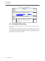
5.3 Beam Design Output
28
Table of Contents
5.3.1 Allowable Stress Design AISC ASD 9th
28
5.3.2 AISC 360-05 ASD and LRFD and AISC LRFD 3rd Edition
35
5.3.3 CAN/CSA S16 01
36
5.3.4 BS 5950
41
5.3.5 Eurocode
47
5.4 Smartbeam Design Output
49
5.4.1 AISC 360-05 ASD (13th Edition)
49
5.4.2 AISC 360-05 LRFD (13th Edition)
54
5.4.3 AISC ASD (9th Edition)
54
5.4.4 AISC LRFD (3rd Edition)
58
5.4.5 Detailed Smartbeam Design
59
5.5 Diagrams
59
5.5.1 Load Diagram
59
5.5.2 Shear, Moment, and Deflection Diagrams
61
Chapter 6 Menus
63
6.1 File menu
63
6.1.1 Job Information dialog
6.2 Criteria menu
65
65
6.2.1 General Criteria dialog
66
6.2.2 Design Criteria dialog
67
6.2.3 Deflection Criteria dialog
74
6.2.4 Camber Criteria dialog
74
6.2.5 Web Openings dialog
75
6.2.6 Smartbeams dialog
76
6.3 Beam menu
78
6.3.1 Span Definition dialog
78
6.3.2 Composite dialog
81
6.3.3 Bracing dialog
83
6.3.4 Layout Web Openings dialog
84
6.3.5 Duct Size dialog
85
User Manual — vi
Table of Contents
6.4 Loads menu
6.4.1 Loads dialog
6.5 Process menu
87
87
89
6.5.1 View/Update Beam dialog
90
6.5.2 Modify Web Opening dialog
93
6.5.3 Smartbeam View Update dialog
96
6.6 Reports menu
6.6.1 Report Preferences dialog
99
100
6.7 View menu
101
6.8 Help menu
102
Chapter 7 Keyboard Shortcuts
105
7.1 Working with Beam Files
105
7.2 Working with Dialogs
106
7.3 Copy, Paste and Delete
107
7.4 View Window
108
Chapter 8 Technical Notes
109
8.1 Steel Design Codes for Steel Beams
109
8.2 Member Loads
110
8.2.1 Load Properties
110
8.2.2 Positive Loads, Negative Loads, and Skip Loading
111
8.3 Composite Beam Design
vii — RAM SBeam
112
8.3.1 Calculating Effective Flange Width
112
8.3.2 Deck Orientation
112
8.3.3 Effect of Slab and Deck Change
113
8.3.4 Shear Stud Connectors
114
8.3.5 Stresses - ASD
118
8.3.6 Capacities - LRFD
118
8.3.7 Capacities - CAN/CSA-S16-01
119
8.3.8 Capacities - BS 5950
119
8.3.9 Capacities - Eurocode
119
Table of Contents
8.4 Non Composite Beam Design
120
8.4.1 CAN/CSA-S16-01
120
8.4.2 BS 5950:1990
121
8.4.3 BS 5950:2000
121
8.5 Design Yield Strength
123
8.5.1 AISC 360-05 and AISC ASD and LRFD
123
8.5.2 CAN/CSA-S16-01
123
8.5.3 BS 5950
123
8.5.4 Eurocode
124
8.6 Material Properties
124
8.6.1 AISC 360-05 and AISC ASD and LRFD
124
8.6.2 CAN/CSA-S16-01
124
8.6.3 BS 5950
124
8.6.4 Eurocode
124
8.7 Cross Section Classification
8.7.1 Cross Section Classification Error Messages
124
125
8.8 Cantilevers
125
8.9 Unbraced Length
126
8.9.1 ASD and LRFD
128
8.9.2 CAN/CSA-S16-01
128
8.9.3 BS 5950
128
8.9.4 Eurocode
129
8.10 Deflection
131
8.10.1 AISC 360-05, AISC LRFD 3rd and AISC ASD 9th
131
8.10.2 CAN/CSA-S16-01
132
8.10.3 BS 5950
132
8.10.4 Eurocode
132
8.11 Camber
132
8.12 Shear
133
8.13 Optimization
133
User Manual — viii
Table of Contents
8.14 Size and Depth Limitation
134
8.15 User Defined Rolled and Built up Shapes
134
8.16 Vibration Analysis
135
8.16.1 Vibration, Frequency and BS 5950
8.17 Web Openings
135
136
8.17.1 Design Guide #2
137
8.17.2 SCI Publication 068
139
Chapter 9 Additional Information
141
9.1 Technical Support
141
9.2 RAM Structural System
141
Appendix A RAM SBeam Tables
143
A.1 Metal Deck Tables
143
A.2 Metal Deck Table File Format
144
A.3 Master Steel Tables
146
A.4 Master Steel Table File Format
147
A.4.1 For Channels
149
A.4.2 For Angles (Ls)
149
A.4.3 For Pipes (Round Hollow Sections)
149
A.5 Design Steel Tables
152
A.6 Beam Design Steel Table Format
154
A.7 Smartbeam Tables - Castellated
156
A.8 Smartbeam Tables - Cellular
158
Appendix B Bison Precast Units
161
ix — RAM SBeam
B.1 To define Bison precast unit decks
161
B.2 Criteria
162
B.3 Technical Notes
162
B.3.1 Precast Units
162
B.3.2 Gap
163
B.3.3 Effective Width of Compression Area
163
B.3.4 Shear Stud Capacity
164
Table of Contents
B.4 Contact
Appendix C Steel and Synthetic Fibers
165
167
C.1 Dramix
167
C.2 FibreFlor
168
C.3 To specify fibers in the floor system
168
C.4 Deck Table
169
C.5 Composite Beam Design
169
C.5.1 Dramix
169
C.5.2 FibreFlor
170
C.6 Beam Design Report
170
C.6.1 Dramix
170
C.6.2 FibreFlor
171
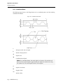
Appendix D Smartbeams
D.1 Technical Notes
D.1.1 Compression Flange Bracing
D.2 Nomenclature
173
173
173
173
D.2.1 Castellated Beam
174
D.2.2 Cellular Beam
175
D.2.3 Section Labels
175
D.2.4 Example
176
D.3 Steel Design Codes for Smartbeams
176
D.4 Castellated Beam Design Procedures
176
D.4.1 AISC 360-05 ASD Design Procedure (13th Edition)
176
D.4.2 AISC 360-05 LRFD Design Procedure (13th Edition)
177
D.4.3 ASD Design Procedure (9th Edition)
179
D.4.4 LRFD Design Procedure (3rd Edition)
180
D.4.5 Deflection
181
D.5 Cellular Beam Design Procedures
181
D.5.1 AISC 360-05 ASD Design Procedure (13th Edition)
181
D.5.2 AISC 360-05 LRFD Design Procedure (13th Edition)
182
User Manual — x
Table of Contents
D.5.3 ASD Design Procedure (9th Edition)
183
D.5.4 LRFD Design Procedure (3rd Edition)
185
D.5.5 Deflection
186
D.6 Contact
186
Index
187
List of Figures and Tables
191
xi — RAM SBeam
Chapter 1
What's New?
An overview of the new features in RAM SBeam v5.0.
1.1 Smartbeams
Smartbeams can now be designed. Select Smartbeam as the material type, specify design
information, and perform a member design for both castellated and cellular beams. Review the
Fundamentals and Designing Smartbeams sections of the program help to learn more.
Additional reference material on Smartbeams has been included in Appendix D .
There are two versions of RAM SBeam. One has all of the capabilities described in this manual,
including both Steel beams and Smartbeams. The other is a special CMC Smartbeam version
that is only capable of doing Smartbeams; that version will not allow you to select Steel as the
material type. That version is available from CMC Steel Products . If you have the CMC
Smartbeam-only version and wish to upgrade to the full version, contact Bentley Systems, Inc.
1.2 Composite Ieff
An option to reduce the effective moment of inertia for composite sections by multiplying by
0.75 per AISC 360 Commentary is now available for all AISC codes. This option is selected in
the Design Criteria dialog Studs tab .
1.3 Eurocode
The implementation of the Eurocode has been updated from the old pre-standard to the new
Eurocode standards, EN 1993-1-1:2005 (Eurocode 4 - Design of Steel Structures) and EN1994-11:2004 (Design of Composite Steel and Concrete Structures).
User Manual — 1
Chapter 1 What's New?
1.4 Launching from RAM Structural System
1.4 Launching from RAM Structural System
RAM SBeam can be launched from the RAM Structural System , with geometry, material,
loads and design criteria passed from the RAM Structural System to RAM SBeam. This link
has been enhanced to include the ability to launch RAM SBeam with CMC Smartbeam data.
The link has also been enhanced to include a more complete set of design and criteria
information.
2 — RAM SBeam v5.0
Chapter 2
Getting Started
This section includes fundamental concepts and tasks needed to use the program as well as
details on the areas of the program window.
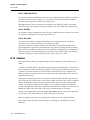
2.1 Fundamentals
Explains some of the core concepts and procedures involved in using the program.
2.1.1 What is RAM SBeam?
An introduction to the program.
RAM SBeam is a powerful program for the design of composite or non-composite beams in
strict accordance with several steel code design requirements. RAM SBeam allows any
combination of point, trapezoidal, and uniform loads, and can be used to select optimum
design for new construction or to check adequacy of existing construction. Member sizes and
stud information selected by the program can be easily overridden by the user if necessary, and
alternate designs can be investigated. The interface provides the designer with a design tool of
unmatched ease of use. Data entry is simplified and intuitive, and data can be entered or
modified in any order
2.1.2 RAM SBeam Directories
A description of the directories installed with the program.
RAM SBeam will create the following three directories unless they are specified otherwise
during installation.
User Manual — 3
Chapter 2 Getting Started
2.1 Fundamentals
PROG
Contains the executable file RAMSBeam.exe, the Help file RAMSBeam.chm, and the
Manual file RAMSBeam.pdf. The default directory is C:\Program Files\Bentley
Engineering\RAMSBEAM\PROG.
Note: Users of the RAM Structural System or other RAM utility programs may
have already established the PROG directory on their computer. RAM SBeam can be
installed in the PROG directory that already exists.
TABLES
Contains the deck and steel beam design tables used by the program. The tables used
by RAM SBeam are the same tables used by the RAM Structural System. The default
directory is C:\Program Files\Bentley Engineering\RAMSBEAM\TABLES.
DATA
Contains the output data files of individual beam runs created when the Save
command is invoked. The default directory C:\Program Files\Bentley
Engineering\RAMSBEAM\DATA.
2.1.3 Documentation Conventions Used
The following typographical and symbolic conventions are used throughout this reference:
Typograhpical Conventions
File Path/File Name.extension
A fixed width typeface is used to indicate file names, file paths, and file extensions
(e.g., C:/Program Files/Bentley/…/Prog/RAMSBeam.exe)
Interface Control
A bold typeface is used to indicate user controls. Menu and sub-menu items are
indicated with a series of > characters to distinguish menu levels. Windows shortcut
keys are underlined. (e.g., File > Save As…).
User Input
A fixed width typeface is used to indicate information which must be manually
entered.
Notes, Tips, and Warnings
Items special note are indicated as follows:
Note: This is an item of general importance.
Tip: This is optional time-saving information.
Warning: This contains information about actions that should not be performed
under normal operating conditions.
4 — RAM SBeam v5.0
Chapter 2 Getting Started
2.1 Fundamentals
Mathematical Notation
Similar to spelling conventions, American mathematical notation is used throughout the
documentation. A serif typeface is typically used to clarify numbers or letters which might
otherwise appear similar.
l
l
l
Numbers greater than 999 are written using a comma (,) to separate every three digits.
For example, the U.S. value of Young's Modulus is taken as 29,000,000 psi.
Numbers with decimal fractions are written with a period to separate whole and
fraction parts. For example, a beam with a length of 21.75 feet.
Multiplication is represented with a raised, or middle, dot ( ). For example, P = F A.
2.1.4 Starting RAM SBeam
Used to initiate the program.
1. RAM SBeam can be started by any one of the following methods:
In the Program Group, select the RAM SBeam icon.
or
in Windows Explorer, double-click a RAM SBeam file (with the file extension .rsb).
or
in Windows Explorer, double-click the icon for the file RAMSBeam.exe.
The RAM SBeam program window opens.
2.1.5 Specify Job Information
Enter job information which will be displayed on screen and used in report headers.
1. Select File > Job Information…
The Job Information dialog opens.
2. Specify a Job Name and/or Comments describing the SBeam job.
3. Select the option to Show this dialog when Print is issued to re-open this dialog
when printing.
4. Click OK.
The dialog closes and the Job Information is saved to the current SBeam file.
2.1.6 Select beam material type
The material selection box displays the currently selected material (steel or Smartbeam). Use
the following procedure to switch the material type.
Note: In the CMC version, only the Smartbeam material is available.
1. Click the drop-down arrow in the material selection box .
2. Select either Steel or Smartbeam for the material.
The beam diagram in the View window updates. Material-specific controls for the
selected material become active.
User Manual — 5
Chapter 2 Getting Started
2.1 Fundamentals
2.1.7 Changing the Unit System
RAM SBeam can accept input and provide output in English (US Imperial), SI or Metric
units.
The capability to change units at any time is useful in the case where a job requires the
production of designs in units in which you are unaccustomed to working. A beam can be
modeled and designed in a familiar system of units. Once the design is completed to your
satisfaction, the units can be changed for the final output reports.
1. Select Criteria > General.
The General Criteria dialog opens.
2. Select the Units tab.
The General Criteria dialog Units tab is displayed.
3. Select the input and output unit system you wish to use.
4. Set the Save as Default option to use this as the default unit system.
5. Click OK.
The dialog closes and the values of all input are updated to display in the selected
system of units.
2.1.8 Changing Criteria and Property Defaults
The default criteria and property values can be customized.
Initial Default Criteria are set during the installation process. You can modify any default
values at any time. Use the following procedure to modify a default value:
1. Select the Criteria menu item containing the default to be changed.
The corresponding dialog opens.
2. Specify one or more new default value(s).
3. Set the Save as Default option.
4. Click OK.
The dialog closes and the specified value(s) are set as the default.
Some material property items can likewise be set as defaults in the Span Definition dialog
and the Composite dialog .
The specified values will now be the default values whenever the program is run.
Tip: It is recommended that all of the defaults be thus specified and modified
immediately after installing the program, if necessary, prior to proceeding with any
designs. Care should be taken to specify all criteria on all tabs of all of the commands,
and it should be done in the order that the commands appear in the menus in the
program.
2.1.9 Exiting RAM SBeam
Exit the program when your are finished with beam designs.
6 — RAM SBeam v5.0
Chapter 2 Getting Started
2.2 Application Window Layout
1. You may exit the program by a number of methods:
Select File > Exit.
or
Click the program close icon in the top-right corner of the program window.
or
Press ALT+F4.
The program window closes.
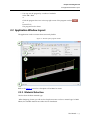
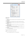
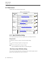
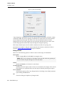
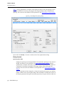
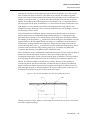
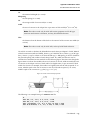
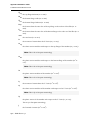
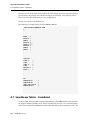
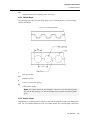
2.2 Application Window Layout
The application window contains these sections by default.
Figure 2-1: Sections of the program window
Refer to the Menus section for a description of the Menu bar items.
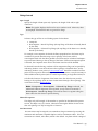
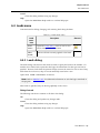
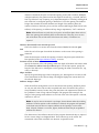
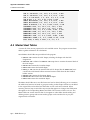
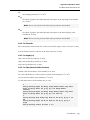
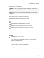
2.2.1 Material Selection
Used to select the beam material type.
When designing a beam, you will use the drop-down menu to select a material type. In RAM
SBeam, the available materials are either Steel or Smartbeam.
User Manual — 7
Chapter 2 Getting Started
2.2 Application Window Layout
Tip: The selector is located at the top, left-hand corner of the program window, just
below the File menu.
Figure 2-2: The material selector
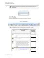
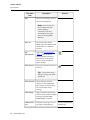
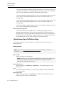
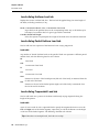
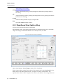
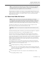
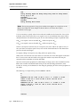
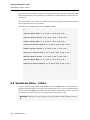
2.2.2 Toolbar
The Primary Tools toolbox is a launch point for commonly used tools.
Figure 2-3: The main toolbar
Tip: The display of the toolbar can be toggled by selecting View > Toolbar.
Table 2-1: Toolbar items
Icon
New
Description
Same Effect
as Selecting…
Used to clear all current data and open an
empty file with the default criteria and
properties.
File > New
Used to open a file that was previously saved
by RAM SBeam.
File > Open
Used to save all of the current criteria
settings, beam geometry, loads, etc. If the
beam size has been specified as a userspecified size (rather than as an optimum
size), the size and studs will be saved as
well.
File > Save
Opens the Span Definition dialog , which is
used to define span lengths and general
beam properties.
Beam > Span
Definition…
Open
Save
Span Info
8 — RAM SBeam v5.0
Chapter 2 Getting Started
2.2 Application Window Layout
Icon
Composite
Info
Define
Bracing
Define
Openings
Duct
Size…
Description
Same Effect
as Selecting…
Opens the Composite dialog , which is used
to edit composite deck and rib spacing
details.
Beam >
Composite…
Opens Bracing dialog , which is used to
define discrete top or bottom flange braces
as well as unbraced top flange segments.
Beam >
Bracing…
Opens the Layout Web Openings dialog ,
which is used to add or edit beam web
openings.
Beam > Web
Opening…
Opens Duct Size dialog , which is used to
specify duct size and shape to be considered
for the design of Smartbeams.
Beam > Duct
Size…
Opens the Load Cases dialog , which is used
to view and/or change loads on the beam.
Loads > Load
Cases…
Designs the beam and opens either the
View/Update Beam dialog or the
Smartbeam View Update dialog .
Process >
Beam
Design…
Toggles the display of flange braces in the
graphical display.
View > Brace
Points
Used to toggle the display of the web
openings and stiffeners on the beam.
View > Web
Openings
Define
Loads
Design
Beam
Show
Brace
Points
Show Web
Openings
Increases the size of text in the View
window.
Scale Text
Up
User Manual — 9
Chapter 2 Getting Started
2.2 Application Window Layout
Icon
Description
Same Effect
as Selecting…
Decreases the size of the text in the View
window.
Scale Text
Down
Orients the beam in the View window to a
perspective view.
View >
Rotate to
Perspective
Orients the beam in the View window to a
profile view.
View >
Rotate to
Profile
Used to increase the View window's
magnification.
View > Zoom
In
Used to decrease the View window's
magnification.
View > Zoom
Out
Opens the Job Information dialog , which is
used to specify optional descriptive
information on the project which is then
included in report headers.
File > Job
Information
Opens the Report Preferences dialog , which
is used to change report options, including
text styles for various parts of the report.
Reports >
Report
Preferences…
Prints the contents of the View window.
File > Print
Screen…
Perspective
View
View
Profile
Zoom In
Zoom Out
Set Job
Name
Report
Preferences
Print
Screen
About
10 — RAM SBeam v5.0
Opens the About RAM SBeam dialog, which Help > About
contains version and copyright
RAM
information.
SBeam…
Chapter 2 Getting Started
2.2 Application Window Layout
2.2.3 Properties Panel
Displays a summary of the beam input and design results.
2.2.4 View window
Displays a graphical representation of the beam, loads, openings, and conditions.
Use controls located in the View menu or on the Toolbar to manipulate the View window.
2.2.5 Status Bar
Displays tips for using the window tool over which the mouse pointer hovers.
Note: The display of the Status Bar can be toggled by selecting View > Status Bar.
2.2.6 Report Viewer window
Used to display reports on screen.
Table 2-2: Report Viewer window controls
Tool
Description
Shortcut
Print the
Opens a Print dialog, which is used to print
Document the current report.
Set Scale
1:1
Displays the report at the default
magnification.
Show Full
Page
Displays the entire report at lowest
magnification.
Zoom In
Increases the magnification.
Insert or
Left-click
Zoom Out
Decreases the magnification.
Delete or
Right-click
Go to
First Page
Displays the first page of the report.
CTRL+Page
Up
Go to
Previous
Page
Displays the previous page of the report.
Page Up
Go to
Next Page
Displays the next page of the report.
Page Down
User Manual — 11
Chapter 2 Getting Started
2.2 Application Window Layout
Tool
Description
Go to Last
Page
Display the last page of the report.
Help on
Control
Opens the Usage dialog, which contains
shortcuts for controlling the report display.
Close
Preview
Closes the Report Viewer window.
Shortcut
CTRL+Page
Down
ALT+F4
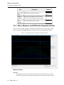
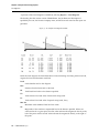
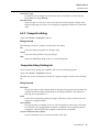
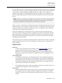
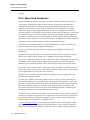
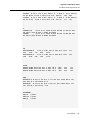
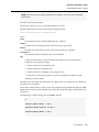
2.2.7 Shear, Moment, and Deflection Diagrams window
Used to review the shear, bending, and deflection diagrams for the current beam design.
Opens when the View Diagrams button is clicked on the View/Update Beam dialog.
Figure 2-4: The Shear, Moment, and Deflection Diagrams window
Window Controls
diagrams
The diagrams are shown using the selected loads. A vertical, yellow line is used to
indicate the mouse position along the length of the beam with the values of shear,
12 — RAM SBeam v5.0
Chapter 2 Getting Started
2.2 Application Window Layout
moments, and deflection being reported at the point to the right side of the respective
diagram.
Load Combination
Select the load combination to display from the drop-down list. Considered
combinations of load specified in the Loads dialog are listed.
load options
Select the load types or load effects to display. Load types are color coded with the
values at the selected location in the diagram legends. Click the checkbox to remove
the load effect from the diagrams.
Print
Opens a Print dialog, which is used to select a printer to which you wish to send the
diagram output.
Cancel
Closes the window.
User Manual — 13
Chapter 2 Getting Started
14 — RAM SBeam v5.0
Chapter 3
Designing Steel Beams
This section details how to evaluate or optimize composite and non-composite steel beams.
3.1 Define the Beam Span
Set the span length, select a material, define composite and bracing action, and specify design
limits.
1.
2.
3.
4.
5.
6.
7.
8.
Select either
Beam > Span Definition…
or
the Span Definition tool found on the toolbar .
The Span Definition dialog opens.
Specify the length of each span.
If one or both cantilevers are not present, simply leave this value as 0.00.
Select a class of beam cross sections to use as the Shape.
Specify a yield strength, Fy, appropriate for the selected Shape.
Set the Type option (i.e., the composite flag) which describes the floor or deck
conditions.
Specify a Span/Depth Limit if necessary.
A higher value will result in a more shallow cross section. Leave the value as zero (0.0)
to have the program ignore the L/d limit.
Specify one or more size restrictions if necessary.
You can limit the size of the resulting design using a range of values here.
Set the Save As Default option to use these settings for future beam designs.
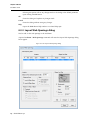
3.2 Define the composite floor system
For composite beams, add the required deck and concrete parameters.
User Manual — 15
Chapter 3 Designing Steel Beams
3.3 Define flange bracing
Prior to defining a composite floor, the span must be defined.
This set of steps is not required for beams which have been flagged as non-composite in the
Span Definition dialog .
1. Select either
Beam > Composite…
or
2.
3.
4.
5.
6.
7.
8.
the Composite Info tool found on the toolbar .
The Composite dialog Decking tab opens.
Specify the Distance to adjacent beams or slab edges in the Deck Span parameters.
Specify the ultimate strength, Fu, Diameter, and Length for the Studs.
The default ultimate strength and diameter may be used but the length value must
also be provided.
Set the Beam is Shored option, if the beam is to be shored.
Specify the Deck and Fill parameters in the table for both left and right sides of the
beam.
Select the options to Save Stud Fu and Stud Diameter as Defaultand/or Save Conc
f'c and Conc Unit Weight as Defaultto use changed values in the future.
Select the Ignore Rib Spacing tab and select the option to Ignore Rib Spacing When
Determining Stud Spacing if this is required.
Be sure to select the appropriate condition for the ribs over the beam top flange.
Click OK to save the composite parameters and close the dialog.
Once the floor system has been defined for a composite beam, you may proceed to define
flange bracing or add web openings if necessary or add loads to the beam .
3.3 Define flange bracing
Used as needed to specify brace points along the top or bottom flange as well as unbraced
segments for otherwise braced top flanges.
Prior to defining bracing points, the span must be defined and, for composite beams, the
floor deck information must be provided .
Bracing points which coincide with concentrated loads (e.g., supporting a secondary beam
framing from either side) can be specified in the Loads dialog Concentrated Loads tab .
1.
Select either
Beam > Bracing…
or
the Define Bracing tool found on the toolbar .
The Bracing dialog opens.
2. Specify the distance to any top and/or bottom flange brace points and select which
flanges are being braced at this point.
3. (For composite beams only) Specify any unbraced segments by adding a beginning
point and end point, as measured from the left end of the beam.
16 — RAM SBeam v5.0
Chapter 3 Designing Steel Beams
3.4 Add web openings
4. Click OK.
The dialog closes and the specified beam bracing is displayed on the beam in the View
window. Yellow pointers are used on flanges to indicate brace points. Top flange braced
segments are indicated with a red line along the flange tip.
3.4 Add web openings
Used to add rectangular or round web openings in the beam.
Prior to adding web openings, the span must be defined and, for composite beams, the floor
deck information must be provided .
Opening can be added or changed in this dialog. Previously defined openings can be modified
using the Modify Web Opening dialog .
1.
Select either
Beam > Web Openings…
or
the Define Openings tool found on the toolbar .
The Layout Web Openings dialog opens.
2. Specify Location information to the center of the opening along the length of the beam.
3. Specify the vertical position of the opening along the depth of the web.
4. Select either the Rectangular or Circular option for the opening shape and specify the
dimensions of the opening.
5. Click the Add button.
The opening information is added to the Web Opening Data table.
6. Repeat steps 2 through 5 to add as many openings as necessary.
7. Click OK.
The dialog closes. The web opening data is saved.
3.5 Apply loads to the beam
Used to add net loads to the beam.
Prior to adding loads, the span must be defined and, for composite beams, the floor deck
information must be provided .
Loads are composed of Dead Load, Construction Dead Load, Live Load, and Construction Load.
After the loads have been specified they are displayed in the View window as applied on the
beam. The total load values (Dead plus Live) are shown.
3.5.1 Add a uniform load
Add a load of uniform force per unit length along the entire beam (cantilevers and main
span).
User Manual — 17
Chapter 3 Designing Steel Beams
3.5 Apply loads to the beam
1.
2.
3.
4.
5.
Either select
Loads > Load Cases…
or
the Define Load tool.
The Loads dialog Uniform Load tab opens.
Specify values for any combination of Dead Load, Construction Dead Load, Live
Load, and Construction Live Load.
Select the option to Consider Beam Self-Weight to superimpose the weight of the
steel beam in addition to the specified uniform Dead Load.
Add loads from other tabs if necessary.
Click OK.
The load data is saves and the dialog closes.
3.5.2 Add a partial uniform load
Add a load of uniform force per unit length over a portion beam.
1.
Either select
Loads > Load Cases…
or
the Define Load tool.
The Loads dialog opens.
2. Select the Partial Uniform Load tab .
3. Specify values for any combination of Dead Load, Construction Dead Load, Live
Load, and Construction Live Load in a row within the table.
4. Specify a Start and End distance for the uniform load.
Tip: Load distances are measured from the far, left end (including cantilever
length). Distances to span ends are shown at supports in the View window.
5. Repeat steps 3 and 4 to add more partial uniform loads.
6. Add loads from other tabs if necessary.
7. Click OK.
The load data is saves and the dialog closes.
3.5.3 Add a trapezoidal load
Add a load of varying force per unit length over a portion of the beam.
1.
Either select
Loads > Load Cases…
or
the Define Load tool.
The Loads dialog opens.
2. Select the Trapezoidal Load tab .
3. Specify values for any combination of Dead Load, Construction Dead Load, Live
Load, and Construction Live Load at both the Left and Right ends of the load in a
row within the table.
18 — RAM SBeam v5.0
Chapter 3 Designing Steel Beams
3.6 Perform the beam design
4. Specify a Distance to the Left and Right end.
Tip: Load distances are measured from the far, left end (including cantilever
length). Distances to span ends are shown at supports in the View window.
5. Repeat steps 3 and 4 to add more trapezoidal loads.
6. Add loads from other tabs if necessary.
7. Click OK.
The load data is saves and the dialog closes.
3.5.4 Add a concentrated load
Add a load of uniform force per unit length over a portion beam.
1.
Either select
Loads > Load Cases…
or
the Define Load tool.
The Loads dialog opens.
2. Select the Concentrated Load tab .
3. Specify values for any combination of Dead Load, Construction Dead Load, Live
Load, and Construction Live Load in a row within the table.
4. Specify a Start and End distance for the uniform load.
Tip: Load distances are measured from the far, left end (including cantilever
length). Distances to span ends are shown at supports in the View window.
5. Repeat steps 3 and 4 to add more concentrated loads.
6. Add loads from other tabs if necessary.
7. Click OK.
The load data is saves and the dialog closes.
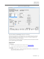
3.6 Perform the beam design
Perform an analysis and design of the steel beam.
As a minimum, the span and loads must be defined prior to performing the design. For beams
flagged as composite, the composite floor system must also be defined.
1. Select one of the following to initiate the beam design:
Process > Beam Design…
or
the Design Beam tool.
The design is performed. Any errors are displayed in warning dialogs. The View/Update
Beam dialog opens.
User Manual — 19
Chapter 3 Designing Steel Beams
3.6 Perform the beam design
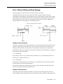
3.6.1 To try a different beam size
Use the following procedure to try a beam size other than the optimized selected by the
program.
1. Open the View/Update dialog .
2. Select the desired size in the Beam Size list.
3. Click the Analyze button.
RAM SBeam performs a beam analysis. Warning dialogs will present any issues with
the selected beam design.
4. Click the Save Design button to save the selected beam design.
3.6.2 To try a different yield strength
Use the following procedure to try a different material grade.
1. Open the View/Update dialog .
2. Enter a new value for the yield strength in the Fy field.
3. Click the Optimize button.
A new beam size is selected by the program.
4. Click the Save Design button to save the selected beam design.
3.6.3 To change composite setting
Use the following procedure to edit the composite flag.
1. Open the View/Update dialog .
2. Select either the Composite or Noncomposite option for the Composite flag.
3. If the composite flag has been set to Composite, then you may also update the Stud
Configuration.
4. Click the Optimize button.
A new beam size is selected by the program.
5. Click the Save Design button to save the selected beam design.
3.6.4 To modify web openings
Use the following procedure to modify the geometry and design of web openings.
Only existing openings can be modified using this procedure. To add or delete an opening,
use the Layout Web Openings dialog .
1. Open the View/Update dialog .
2. Click the Modify>> button.
The Modify Web Opening dialog opens, displaying the opening and stiffener data
which can be modified as desired.
3. Select from the Opening Data table the opening to be modified.
4. Modify any values or options.
5. Click the Change button.
6. Repeat steps 3 through 5 for each opening for which modifications are desired.
20 — RAM SBeam v5.0
Chapter 3 Designing Steel Beams
3.6 Perform the beam design
7. Click OK.
The dialog closes.
8. In the View/Update dialog, click the Analyze button.
The beam is analyzed for changes made in both the View/Update and Modify Web
Opening dialogs. The Pass/Fail status of the web-opening and/or stiffener design is
displayed in the Web Opening Data table.
User Manual — 21
Chapter 3 Designing Steel Beams
22 — RAM SBeam v5.0
Chapter 4
Designing CMC Smartbeams™
This section details how to evaluate or optimize castellated or cellular Smartbeams.
Smartbeam™ is a proprietary product of CMC Steel Products (formerly known as SMI Steel
Products). It comes in two varieties: Castellated (with hexagonal web openings) and Cellular
(with round web openings). Smartbeam design has been implemented in the RAM SBeam. A
Smartbeam is created from a standard wide-flange beam by cutting it longitudinally in a zigzag or semi-circular pattern, separating and offsetting the two halves, and welding them back
together. The result is a deeper, stiffer beam of the same weight as the original. Also, the
resulting holes in the webs permit mechanical ducts, plumbing, and electrical lines to pass
through the beam rather than beneath the beam. Smartbeams may be designed as either
composite or noncomposite beams.
Note: The procedures which are different from steel beams or unique to Smartbeams are
detailed within this section. Many of the steps involved in the design of Smartbeams are
the same as how you design a steel beam.
4.1 Define Smartbeam Criteria
Specify the opening value increments and method of deflection calculation to use in design.
1.
Select Criteria > Smartbeams…
The Smartbeams dialog opens.
2. Specify dimension increment values to be used in Castellated and/or Cellular beam
design.
3. Select the method to use for calculation of Noncomposite Deflection.
User Manual — 23
Chapter 4 Designing CMC Smartbeams™
4.2 Define the Beam Span
4.
Select to Save As Default to use these settings for future Smartbeam designs.
Tip: This can save you the effort of repeating these steps for each design.
5. Click OK.
The dialog closes and your changes are saved.
4.2 Define the Beam Span
Set the span length, select a material, define composite and bracing action, and specify design
limits.
1.
Select either
Beam > Span Definition…
or
the Span Definition tool found on the toolbar .
The Span Definition dialog opens.
2. Specify the span length.
3. Select a either a Castellated or Cellular Smartbeam.
4. Specify a yield strength, Fy.
Warning: Consult with CMC before specifying any value other than 50 ksi.
5. Set the Type option (i.e., the composite flag) which describes the floor or deck
conditions.
6. Specify a Span/Depth Limit if necessary.
A higher value will result in a more shallow cross section. Leave the value as zero (0.0)
to have the program ignore the L/d limit.
7. Specify the Connection Type at each end of the beam.
8. Specify one or more size restrictions if necessary.
You can limit the size of the design results using a range of values here.
9. Set the Save As Default option to use these settings for future beam designs.
For Smartbeams with composite type floors, the composite floor system must be defined. This
procedure is the same as for steel beams .
4.3 Specify a duct size
Used to specify the size of mechanical ducts that the web openings in the Smartbeam must
accommodate.
Prior to specifying a duct size, the span must be defined and, for composite Smartbeams, the
floor deck information must be provided.
1.
Select either
Beam > Duct Size…
or
the Duct Size tool.
24 — RAM SBeam v5.0
Chapter 4 Designing CMC Smartbeams™
4.4 Perform the Smartbeam design
The Duct Size dialog opens.
2. If a duct is to be specified, select either the Rectangular or Round option and specify
dimensions.
If you are clearing a previous duct size definition, select the No Duct Specified option.
3. Set the Save As Default option if this duct size is to be used for future designs.
4. Click OK.
The dialog closes. The duct size information is saved and is displayed in the Properties
Panel.
4.4 Perform the Smartbeam design
Perform an analysis and design of the Smartbeam.
As a minimum, the span and loads must be defined prior to performing the design. For
Smartbeams flagged as composite, the composite floor system must also be defined.
1.
Select one of the following to initiate the beam design:
Process > Beam Design…
or
the Design Beam tool.
The design is performed. Any errors are displayed in warning dialogs. The Smartbeam
View Update dialog opens.
4.4.1 To infill a web opening
Used to fill a web opening in a Smartbeam where necessary (e.g., a transfer column).
The ability to infill openings can only be performed on beams with a specific DT, e and phi in
the case of Castellated beams and Do and S in the case of Cellular beams.
Note: Distance e or S is specific if the minimum and maximum values assigned to the
range are the same. To infill an opening, double-click the opening in the graphic at the
bottom of the View/Update dialog box or double-click an opening location in the
Openings Data list. To remove infills, double-click the infill in the graphic or opening
location in the Openings Data list.
1. Open the View/Update dialog.
2. Deselect the Optimize checkbox for
Dt and e min/max, in the case of a castellated beam
or
Diameterand S min/max, in the case of a cellular beam.
You are now able to specify a these values directly rather than use the program
optimized values or ranges.
3. Enter the same value in the
e min/max, in the case of a castellated beam
or
S min/max, in the case of a cellular beam.
User Manual — 25
Chapter 4 Designing CMC Smartbeams™
4.4 Perform the Smartbeam design
4. For castellated beams, set the Use option for phi. Specify a value for Top Tee phi or
Bottom Tee phi as needed.
5. Click either
the Analyze button, to analyze the current beam size for the other specified data
or
the Optimize button, to have the program select an optimum beam size for the
specified data.
The program reports results of the procedure.
6. To mark an opening as infilled, either
double click the Opening Data table row for the opening
or
double click the opening in the beam elevation diagram.
The Infill column in the Opening Data table row is marked Yes and the opening is
shaded in the diagram. Repeat this step for other openings as needed.
7. Click the Analyze button.
The results are updated with an analysis accounting for infilled openings.
26 — RAM SBeam v5.0
Chapter 5
Output and Creating Reports
RAM SBeam output is designed to provide the engineer with all the necessary data for review
of, and calculation submission for, a beam design.
Except for the calculation of loads, the need for hand calculations is virtually eliminated for
most beam designs.
RAM SBeam output is designed to provide the engineer with all the necessary data for review
of, and calculation submission for, a beam design. Except for the calculation of loads, the need
for hand calculations is virtually eliminated for most beam designs.
5.1 Generating a Design Report
Used to output a report for the current beam design.
1. Perform a successful beam design.
Reports are not available until the beam has been designed.
2. Select the desired output destination (Screen, Printer, Text File, or Viewer File) from
the Reports menu.
A check mark is displayed next to the current report destination.
3. Select Reports > Beam Design.
Note: If the Show this dialog when Print is issued option was selected in the
Job Information dialog , the Job Information dialog opens allowing you to edit the
Header information for the report.
4. Make any desired changes to the Job Information.
5. Click OK.
If Screen is the selected destination, the Report opens in the Report Viewer window. If
Printer is the selected destination, a Print dialog opens to generate a hard copy of the
User Manual — 27
Chapter 5 Output and Creating Reports
5.2 Print a copy of the shear, moment, and deflection diagrams
design report. Otherwise, a Save As dialog opens prompting you to select a file name
and location for the selected file type.
5.2 Print a copy of the shear, moment, and deflection
diagrams
Create a hard copy of the beam shear, bending, and deflection diagrams.
The span definition and load information must be specified in order to view the diagrams.
Composite floor data must also be specified for composite beams.
1. Select one of the following to initiate the beam design:
Process > Beam Design…
or
2.
3.
4.
5.
6.
7.
8.
the Design Beam tool.
The design is performed or, for a frozen design, the be is analyzed. For steel beams, the
View/Update Beam dialog opens and for Smartbeams, the Smartbeam View Update
dialog opens.
Click the View Diagrams button.
The Shear, Moment, and Deflection Diagrams window opens.
Select the desired Load Combination.
The diagrams update to reflect the selection.
Select the load effects you wish to display.
The diagrams update to reflect the selection.
Click the Print button.
A Windows Print dialog opens.
Select the printer and printer settings you wish to use.
Click the Print button.
The dialog closes. Focus returns to the Shear, Moment, and Deflection Diagrams
window.
Click the Cancel button.
The window closes. Focus returns to the View Update dialog for the current material.
5.3 Beam Design Output
The following is a brief description of the output provided by RAM SBeam for steel beam
designs.
Note: Output in English (US Imperial), SI or metric units can be obtained by setting
the model units on the General Criteria dialog Units tab .
5.3.1 Allowable Stress Design AISC ASD 9th
This output contains a complete description of individual beam designs. Beam size, span
length, yield strength, composite properties, loading patterns, moments, reactions and
deflections are all included in this output.
28 — RAM SBeam v5.0
Chapter 5 Output and Creating Reports
5.3 Beam Design Output
Page Heading
The heading lists the current version of RAM SBeam, the Job Name and Description if
specified by the user, the licensee Company name, and the date and time that the report was
generated.
Steel Code
Steel Code
The steel design code selected and used in the design of the beam.
Span Information
Depth or Width Limitation Specified
If any beam depth or width limitations have been specified, they will be listed.
Beam Size
Designed beam size. It is either the optimum size selected by the program or the user
selected size.
Steel Yield Strength (Fy)
User-specified yield strength for the beam.
Total Beam Length
Total length of the beam measured from the centerline of supports or, when there are
cantilevers, from end of cantilever to end of cantilever. When cantilevers are present,
the length of the cantilever and its position (right or left) along the beam is also shown.
Top Flange Braced/Unbraced
For non-composite beams, the specified bracing condition of the top flange.
Section Properties
This information will only be listed for built up sections or for asymmetric rolled sections.
Depth
Total depth of the steel section.
Tw
Web thickness.
BfTop
Top flange width.
TfTop
Top flange thickness.
BfBot
Bottom flange width.
TfBot
Bottom flange thickness.
Area
Total area of the steel section.
Ix
Moment of inertia of the steel section.
User Manual — 29
Chapter 5 Output and Creating Reports
5.3 Beam Design Output
Composite Properties (for composite design)
Concrete Thickness
Concrete thickness that exists above the flutes of the metal deck. The thickness is
shown for the left and right side of the beam in case differences occur.
Unit Weight of Concrete
Weight of the concrete. The weight is given for the left and right side of the beam in
case differences occur.
f'c
Strength of the concrete. The strength is given for the left and right side of the beam
in case differences occur.
Decking Orientation
Angle of the metal deck span, measured in degrees, from the referenced beam. The
angle is given for the left and right side of the beam in case differences occur. The
deck span will be considered “Parallel” with a beam if it is oriented within 10 degrees
of that beam.
Decking Type
Type of deck that was selected by the user. The deck type is given for the left and right
side of the beam in case differences occur.
beff
Effective concrete flange width used in the composite design of the beam.
Y bar
Distance from the bottom of the steel beam to the neutral axis of the composite
section used for deflection calculations.
Seff
Effective section modulus of the composite section for partial composite action.
Str
Section modulus for the transformed composite section referenced from the bottom
flange of the steel beam.
Ieff
Effective moment of inertia of the composite section for partial composite action.
Itr
Moment of inertia for the transformed composite section.
Stud Length
Nominal length of shear stud as selected by the user.
Stud Diameter
Nominal diameter of the shear stud as selected by the user.
Stud Capacity (q)
Shear capacity of a single shear stud. When multiple rows of studs are required, the
shear capacity of a stud in a single row is indicated by q[1], that of a stud in a double
row by q[2], and that of a stud in a triple row by q[3].
# of Studs
Number of studs required for the design of the beam. The number of studs is given for
full composite action (or maximum, if full composite action cannot be obtained),
partial composite action and the actual number used. Unless otherwise specified by the
user the actual and the partial number of studs will be the same. When there exists a
point load on the designed beam, a series of studs may be listed with a comma
30 — RAM SBeam v5.0
Chapter 5 Output and Creating Reports
5.3 Beam Design Output
separating them. Each number represents the number of studs required between each
point load or segment, starting at the left support.
Number of Stud Rows
Number of rows of studs necessary to place the number of studs called for.
Percent of Full Composite Action
Percent of full composite action corresponding to the number and distribution of studs
specified for Actual.
User Defined Unbraced Top Flange Segments
This information will not be listed if the beam has been specified as Non-composite Unbraced
Top Flange, and will only be listed if there are segments of the top flange that have been
explicitly specified as unbraced.
From / To
Indicates the beginning and end of each segment of top flange that is unbraced.
User Defined Flange Brace Points
This information will be listed if there are any user-specified flange brace points (points at
which the flange is braced against lateral translation or buckling).
Dist
Location of the flange brace point, measured from the left end of the beam.
Top
Indicates whether or not the top flange is braced at that location.
Bottom
Indicates whether or not the bottom flange is braced at that location.
Loading Information - Point Loads
Dist
Location of the point load represented as a distance measured from the left end of the
beam.
DL
Magnitude of the dead load.
CDL
Magnitude of the construction (pre-composite) dead load.
LL
Magnitude of the live load.
CLL
Magnitude of the construction live load.
Flange Bracing
Indicates whether or not this point is also considered to be a compression flange brace
point. Top Flange and Bottom Flange are indicated.
Loading Information - Line Loads
Load
User Manual — 31
Chapter 5 Output and Creating Reports
5.3 Beam Design Output
This is the line load segment number. Each line load segment is defined by two rows
of output: the beginning of the line load segment is listed on the same line of output
as the segment number, the end of the line load segment is listed on the following
line of output.
Dist
Distance, measured from the left end of the beam, to the beginning or end of a line
load, for the given load segment.
DL
Magnitude of the dead load at Dist.
CDL
Magnitude of the construction (pre-composite) dead load at Dist.
LL
Magnitude of the live load at Dist.
CLL
Magnitude of the construction live load at Dist.
Shear
Max V
Maximum shear force in the member, with the controlling load combination listed.
fv
Actual shear stress, associated with the maximum shear.
Fv
Allowable shear stress.
Moments
This section gives the magnitude and location of the maximum positive and negative
moments with the associated stresses.
Span
Span for which the values are being listed. It includes Left for left cantilever, Right for
right cantilever, and Center for main span.
Cond
Load condition. It includes:
l
l
l
l
l
PreCmp: Construction Dead Load and Construction Live Load (listed for
composite beams only)
InitDL: Initial, or Construction Dead Load (listed for composite beams only)
Max +: Maximum Positive Moment
Max -: Maximum Negative Moment
Mmax/Seff: Stress condition based on the composite properties (listed for
composite beams only)
Mconst/Sx+Mpost/Seff: Stress condition based on the superposition of stress (listed for
composite beams only).
Moment
Moment for the indicated Span and Condition.
@
Location of the indicated moment, measured from the left end of the beam.
32 — RAM SBeam v5.0
Chapter 5 Output and Creating Reports
5.3 Beam Design Output
Lb
Unbraced length for the segment containing the indicated moment. If unbraced length
was not considered, as for a simple span composite beam, Lb is indicated with “--”.
Otherwise, if the compression flange is fully braced throughout the segment, Lb is
indicated with “0.0”, meaning there is no unbraced length to be considered.
Cb
Bending Coefficient. If the unbraced length is zero, Cb is indicated with “---”.
fb
Actual bending stress in the beam for the moment indicated. Values for the Tension
Flange and Compression Flange are included.
Fb
Allowable bending stress for the segment. Values for the Tension Flange and
Compression Flange are included.
Controlling
Controlling set of values.
fc
Compressive stress in the concrete.
Fc
Allowable compressive stress in the concrete.
Reactions
This section gives the reactions at the supports due to various load conditions. Load
conditions include: initial, dead load, maximum positive and negative live load, and
maximum positive and negative total load.
Deflections - Center Span
If the beam has web openings, Multipliers for effects of Web Openings are listed. These values
are all 1.0, indicating that the effects of web openings on the deflection have not been
considered in the calculation of the deflections.
Note: For the deflection values listed, (-) indicates downward deflection and (+)
indicates upward deflection.
Initial Load
Deflection due to the initial loads (the construction dead load only). This deflection
occurs prior to composite action. The location of the deflection output corresponds to
the location of the maximum positive or negative total load deflection. As such it may
not be the maximum deflection for this load case. Refer to the Technical Notes for
further information. This is listed for composite beams only.
Dead Load
Deflection due to the dead load. The location of the deflection output corresponds to
the location of the maximum positive or negative total load deflection. As such it may
not be the maximum deflection for this load case. Refer to the Technical Notes for
further information. This is listed for non-composite beams only.
User Manual — 33
Chapter 5 Output and Creating Reports
5.3 Beam Design Output
Live Load
Deflection due to the live load (on the composite beam section for composite beams).
The location of the deflection output corresponds to the location of the maximum
positive or negative total load deflection. As such it may not be the maximum
deflection for this load case. Refer to the Technical Notes for further information.
Post Com Load
Deflection due to the total load minus the initial load on the composite beam section.
The location of the deflection output corresponds to the location of the maximum
positive or negative total load deflection. As such it may not be the maximum
deflection for this load case. Refer to the Technical Notes for further information. This
is listed for composite beams only.
Net Total Load
Maximum deflection due to all loads, minus the specified camber, if any.
L/D
Span-to-deflection ratio.
Deflections - Cantilever
Note: (-) indicates downward deflection and (+) indicates upward deflection.
Init load
Deflection at the end of the cantilever due to the initial load (i.e. construction dead
load). This is listed for composite beams only. Dead Load: Deflection at the end of the
cantilever due to the dead load. This is listed for non-composite beams only.
Pos Live Load
Deflection at the end of the cantilever due to the positive live load.
Neg Live Load
Deflection at the end of the cantilever due to the negative live load.
Pos Post Comp Load
Deflection at the end of the cantilever due to the total positive load minus the initial
load. This is listed for composite beams only.
Neg Post Comp Load
Deflection at the end of the cantilever due to the total negative load minus the initial
load. This is listed for composite beams only.
Pos Total Load
Total deflection on the end of the cantilever due to all positive loads.
Neg Total Load
Total deflection on the end of the cantilever due to all negative loads.
L/D
Span-to-deflection ratio.
Web Openings
This section lists the web opening geometry, stiffener design and analysis results.
In the Stiffener information, Sides indicates the number of sides of the beam web at which
stiffeners are to be placed: 0 indicates no stiffeners, 1 indicates a pair of stiffeners on one side
of web only, and 2 indicates a pair of stiffeners on both sides of web.
34 — RAM SBeam v5.0
Chapter 5 Output and Creating Reports
5.3 Beam Design Output
The weld size is listed and is assumed to be continuous on both sides of the stiffener plate for
the full length.
Additional design requirements are also shown, including the minimum radii of the corners
of rectangular openings, minimum slab reinforcement in the vicinity of the opening, and
minimum stud requirements in the vicinity of the opening.
Design Warnings, if any, are listed for each opening. “Fail” is indicated for those conditions for
which the opening or stiffener is unacceptable.
5.3.2 AISC 360-05 ASD and LRFD and AISC LRFD 3rd
Edition
Most of the beam output for AISC 360-05 and LRFD 3rd is the same as ASD 9th. Therefore, only
the items that are different are listed below.
Span Information
Mp: Plastic moment of the steel section for members designed non-composite.
Composite Properties
Mnf
Nominal flexural strength of the beam based on full composite action.
Mn
Nominal flexural strength of the beam based on partial composite action.
C
Effective concrete flange force based on partial composite action.
PNA
Plastic Neutral Axis of the composite section.
Shear Capacity (Qn)
Ultimate shear capacity of a single shear stud. When multiple rows of studs are
required, the shear capacity of a stud in a single row is indicated by Qn[1], that of a
stud in a double row by Qn[2], and that of a stud in a triple row by Qn[3].
Rg, Rp
For AISC 360-05 ASD and AISC 360-05 LRFD the capacity of each stud (Qn) is a
function of the Rg and Rp parameters as described in Shear Stud Connectors . For each
stud row the associated Rg and Rp values are also displayed as described for the shear
capacity above.
Shear (Ultimate)
Max Vu
Maximum ultimate shear in the member.
Vn
Nominal shear capacity.
User Manual — 35
Chapter 5 Output and Creating Reports
5.3 Beam Design Output
Moments (Ultimate)
This section gives the magnitude and location of the design moments with the associated
capacities.
Span
Span for which the values are being listed. It includes Left for left cantilever, Right for
right cantilever, and Span for main span.
Cond
Load condition. It includes:
l
l
l
l
Pre Comp: Construction Dead Load and Construction Live Load (listed for
composite beams only)
Init DL: Initial, or Construction Dead Load (listed for composite beams only)
Max +: Maximum Positive Moment
Max -: Maximum Negative Moment
LoadCombo
Controlling Load Combination for the span and condition indicated.
Mu
Ultimate moment for the indicated Span, Condition and Load Combination.
@
Location of the indicated moment, measured from the left end of the beam.
Lb
Unbraced length for the segment containing the indicated moment. If unbraced
length was not considered, as for a simple span composite beam, Lb is indicated with
“---”. Otherwise, if the compression flange is fully braced throughout the segment, Lb
is indicated with “0.0”, meaning there is no unbraced length to be considered.
Cb
Bending Coefficient. If the unbraced length is zero, Cb is indicated with “---”.
Phi
This is the Resistance Factor for AISC 360-05 LRFD and LRFD 3rd editions.
W
This is the Omega factor for AISC 360-05 ASD.
Phi*Mn
This is the design strength of the beam segment for AISC 360-05 LRFD and LRFD 3rd.
Mn / W
This is the design strength of the beam segment for AISC 360-05 ASD.
5.3.3 CAN/CSA S16 01
This output contains a complete description of individual beam designs. Beam size, span
length, yield strength, composite properties, loading patterns, moments, reactions and
deflections are all included in this output.
Page Heading
The heading lists the current version of RAM SBeam, the Job Name and Description if
specified by the user, the licensee Company name, and the date and time that the report was
generated.
36 — RAM SBeam v5.0
Chapter 5 Output and Creating Reports
5.3 Beam Design Output
Steel Code
Steel Code
The steel design code selected and used in the design of the beam.
Span Information
Depth or Width Limitation Specified
If any beam depth or width limitations have been specified, they will be listed.
Beam Size
Designed beam size. It is either the optimum size selected by the program or the user
selected size.
Steel Yield Strength (Fy)
User-specified yield strength for the beam.
Steel Design Yield Strength (Design Fy)
Design yield strength according to the steel grade and the rules of Table 6-3 in the
CISC Handbook of Steel Construction 7th edition.
Grade
Designated grade for the section. See Design Yield Strength for more information on
how the grade is determined.
Total Beam Length
Total length of the beam measured from the centerline of supports or, when there are
cantilevers, from end of cantilever to end of cantilever. When cantilevers are present,
the length of the cantilever and its position (right or left) along the beam is also shown.
Top Flange Braced/Unbraced
For non-composite beams, the specified bracing condition of the top flange.
Section Properties
This information will only be listed for built up sections or for unsymmetric rolled sections.
Depth
Total depth of the steel section.
Tw
Web thickness.
BfTop
Top flange width.
TfTop
Top flange thickness.
BfBot
Bottom flange width.
TfBot
Bottom flange thickness.
Area
Total area of the steel section.
Ix
Moment of inertia of the steel section.
User Manual — 37
Chapter 5 Output and Creating Reports
5.3 Beam Design Output
Composite Properties (Composite Beams)
Concrete Thickness
Concrete thickness that exists above the flutes of the metal deck. The thickness is
shown for the left and right side of the beam in case differences occur.
Unit Weight of Concrete
Weight of the concrete. The weight is given for the left and right side of the beam in
case differences occur.
f'c
Strength of the concrete. The strength is given for the left and right side of the beam
in case differences occur.
Decking Orientation
Angle of the metal deck span, measured in degrees, from the referenced beam. The
angle is given for the left and right side of the beam in case differences occur. The
deck span will be considered “Parallel” with a beam if it is oriented within 10 degrees
of that beam.
Decking Type
Type of deck that was selected by the user. The deck type is given for the left and right
side of the beam in case differences occur.
beff
Effective concrete flange width used in the composite design of the beam.
Y bar
Distance from the bottom of the steel beam to the neutral axis of the composite
section.
Mrcf
Flexural strength of the composite beam based on full composite action.
Mrc
Flexural strength of the composite beam at the point of maximum moment, based on
partial composite action.
C
Effective concrete flange force based on partial composite action.
PNA
Plastic neutral axis of the composite section.
St
Section modulus for the transformed composite section referenced from the bottom
flange of the steel beam.
Ieff
Effective moment of inertia of the composite section for partial composite action.
Itr
Moment of inertia for the transformed composite section.
Stud Length
Nominal length of shear stud as selected by the user.
Stud Diameter
Nominal diameter of the shear stud as selected by the user.
Stud Capacity (qr)
Shear capacity of a single shear stud. When multiple rows of studs are required, the
shear capacity of a stud in a single row is indicated by qr[1], that of a stud in a double
row by qr[2], and that of a stud in a triple row by qr[3].
38 — RAM SBeam v5.0
Chapter 5 Output and Creating Reports
5.3 Beam Design Output
# of Studs
Number of studs required for the design of the beam. The number of studs is given for
full composite action (or maximum, if full composite action cannot be obtained),
partial composite action and the actual number used. Unless otherwise specified by the
user the actual and the partial number of studs will be the same. When there exists a
point load on the designed beam, a series of studs may be listed with a comma
separating them. Each number represents the number of studs required between each
point load or segment, starting at the left support.
Number of Stud Rows
Number of rows of studs necessary to place the number of studs called for.
Percent of Full Composite Action
Percent of full composite action that will be obtained if the number and distribution of
studs conform to that specified for Actual. It represents the worst condition from any
segment.
User Defined Unbraced Top Flange Segments
This information will not be listed if the beam has been specified as Non-composite Unbraced
Top Flange, and will only be listed if there are segments of the top flange that have been
explicitly specified as unbraced.
From / To
Indicates the beginning and end of each segment of top flange that is unbraced.
User Defined Flange Brace Points
This information will be listed if there are any user-specified flange brace points (points at
which the flange is braced against lateral translation or buckling).
Dist
Location of the flange brace point, measured from the left end of the beam.
Top
Indicates whether or not the top flange is braced at that location.
Bottom
Indicates whether or not the bottom flange is braced at that location.
Loading Information - Point Loads
See Allowable Stress Design AISC for a description of this information.
Loading Information - Line Loads
See Allowable Stress Design AISC for a description of this information.
Shear
Max Vfx
Maximum shear force in the member and the load combination that resulted in this
load.
Vrx
Shear capacity of the member.
User Manual — 39
Chapter 5 Output and Creating Reports
5.3 Beam Design Output
Moments
This section gives the magnitude and location of the design moments with the associated
capacities.
Span
Span for which the values are being listed. It includes Left for left cantilever, Right for
right cantilever, and Center for main span.
Cond
This indicates the load condition. It includes:
l
l
l
l
Pre Comp: Construction Dead Load and Construction Live Load (listed for
composite beams only)
Init DL: Construction Dead Load (listed for composite beams only)
Max +: Maximum Positive Moment
Max -: Maximum Negative Moment
LoadCombo
Controlling Load Combination for the span and condition indicated.
Mfx
Ultimate moment for the indicated Span, Condition and Load Combination.
@
Location of the indicated moment, measured from the left end of the beam.
Lb
Unbraced length for the segment containing the indicated moment. If the
compression flange is fully braced throughout the segment, Lb is indicated with “---”,
meaning there is no unbraced length to be considered.
w2 (Omega2)
Equivalent uniform moment bending coefficient. If the unbraced length is zero w2 is
indicated with “---”.
Class
Section class based on the controlling loads for this condition.
Mrx
Design strength of the beam segment.
Controlling
Controlling set of values.
Tension Flange Stress
This section is applicable for unshored composite beams only.
Precomposite Moment
Design moment due to the loads that are applied to the bare beam prior to composite
action. It only includes the Construction Dead Load.
Superimposed Moment
Design moment due to the loads applied to the beam after composite action occurs.
Mpre/Sx
Precomposite moment divided by the elastic section modulus of the bare beam, Sx. It
is the stress caused by the precomposite moment.
40 — RAM SBeam v5.0
Chapter 5 Output and Creating Reports
5.3 Beam Design Output
Msuper/St
Superimposed moment divided by the effective section modulus of the composite
beam, St. It is the stress caused by the superimposed moment.
Reactions
This section gives the reactions at the supports due to various load conditions. Load
conditions include: initial, dead load, maximum positive and negative live load, and
maximum positive and negative total load.
Deflections
nt
Modular ratio used in the calculation of shrinkage deflections of composite beams.
Refer to Allowable Stress Design AISC for definitions of additional items.
5.3.4 BS 5950
This output contains a complete description of individual beam designs. Beam size, span
length, yield strength, composite properties, loading patterns, moments, reactions and
deflections are all included in this output.
Page Heading
The heading lists the current version of RAM SBeam, the Job Name and Description if
specified by the user, the licensee Company name, and the date and time that the report was
generated.
Steel Code
Steel Code
The steel design code selected and used in the design of the beam.
Span Information
Depth or Width Limitation Specified
If any beam depth or width limitations have been specified, they will be listed.
Beam Size
Designed beam size. It is either the optimum size selected by the program or the user
selected size.
Steel Nominal Yield Strength (py)
User-specified nominal yield strength for the beam.
Steel Design Yield Strength (Design py)
Design yield strength according to the steel grade and the rules of Table 6 in the
BS5950:Part1:1990 Structural Use of Steelwork in Building.
Grade
See Design Yield Strength for more information on how the grade is determined.
Total Beam Length
Total length of the beam measured from the centerline of supports or, when there are
cantilevers, from end of cantilever to end of cantilever. When cantilevers are present,
User Manual — 41
Chapter 5 Output and Creating Reports
5.3 Beam Design Output
the length of the cantilever and its position (right or left) along the beam is also
shown.
Top Flange Braced/Unbraced
For non-composite beams, the specified bracing condition of the top flange.
Section Properties
This information will only be listed for built up sections or for unsymmetric rolled sections.
Depth
Total depth of the steel section.
Tw
Web thickness.
BfTop
Top flange width.
TfTop
Top flange thickness.
BfBot
Bottom flange width.
TfBot
Bottom flange thickness.
Area
Total area of the steel section.
Ix
Moment of inertia of the steel section.
Composite Properties (Composite Beams)
Concrete Thickness
Concrete thickness that exists above the flutes of the metal deck. The thickness is
shown for the left and right side of the beam in case differences occur.
Unit Weight of Concrete
Weight of the concrete. The weight is given for the left and right side of the beam in
case differences occur.
fcu
Strength of the concrete (cube strength). The strength is given for the left and right
side of the beam in case differences occur.
Decking Orientation
Angle of the metal deck span, measured in degrees, from the referenced beam. The
angle is given for the left and right side of the beam in case differences occur. The
deck span will be considered “Parallel” with a beam if it is oriented within 10 degrees
of that beam.
Decking Type
Type of deck that was selected by the user. The deck type is given for the left and right
side of the beam in case differences occur.
be
Effective concrete flange width used in the composite design of the beam.
Y bar
Distance from the bottom of the steel beam to the elastic neutral axis of the composite
section.
42 — RAM SBeam v5.0
Chapter 5 Output and Creating Reports
5.3 Beam Design Output
Mcf
Flexural strength of the composite beam based on full composite action.
Mc
Flexural strength of the composite beam at the point of maximum moment, based on
partial composite action.
C
Effective concrete flange force based on partial composite action.
PNA
Plastic neutral axis of the composite section.
Modular Ratio
Effective modular ratio used in the calculation of the elastic section properties to the
composite beam, considering the proportions of the loads that are long term and short
term.
Ip
Effective moment of inertia of the composite section.
Stud Length
Nominal length of shear stud as selected by the user.
Stud Diameter
Nominal diameter of the shear stud as selected by the user.
Stud Capacity (Qp)
Shear capacity of a single shear stud. When multiple rows of studs are required, the
shear capacity of a stud in a single row is indicated by Qp[1], that of a stud in a double
row by Qp [2], and that of a stud in a triple row by Qp [3].
# of Studs
Number of studs required for the design of the beam. The number of studs is given for
full composite action (or maximum, if full composite action cannot be obtained),
partial composite action and the actual number used. Unless otherwise specified by the
user the actual and the partial number of studs will be the same. When there exists a
point load on the designed beam, a series of studs may be listed with a comma
separating them. Each number represents the number of studs required between each
point load or segment, starting at the left support.
Number of Stud Rows
Number of rows of studs necessary to place the number of studs called for.
Percent of Full Composite Action
Percent of full composite action that will be obtained if the number and distribution of
studs conform to that specified for Actual. It represents the worst condition from any
segment.
User Defined Unbraced Top Flange Segments
This information will not be listed if the beam has been specified as Non-composite Unbraced
Top Flange, and will only be listed if there are segments of the top flange that have been
explicitly specified as unbraced.
From / To
Indicates the beginning and end of each segment of top flange that is unbraced.
User Manual — 43
Chapter 5 Output and Creating Reports
5.3 Beam Design Output
User Defined Flange Brace Points
This information will be listed if there are any user-specified flange brace points (points at
which the flange is braced against lateral translation or buckling).
Dist
Location of the flange brace point, measured from the left end of the beam.
Top
Indicates whether or not the top flange is braced at that location.
Bottom
Indicates whether or not the bottom flange is braced at that location.
Loading Information - Point Loads
See Allowable Stress Design AISC for a description of this information.
Loading Information - Line Loads
See Allowable Stress Design AISC for a description of this information.
Load Combinations
The load combinations considered in the design of the beam. These combinations are
referenced by number in the Shear and Moment section as described below.
Shear
LCo
Number of the load combination that controlled the shear design. In reference to the
load combinations listed above.
Max Fvx
Maximum shear force in the member.
Pvx
Shear capacity of the member.
Moments
This section gives the magnitude and location of the design moments with the associated
capacities.
Span
Span for which the values are being listed. It includes Left for left cantilever, Right for
right cantilever, and Center for main span.
Cond
Load condition. It includes:
l
l
l
l
44 — RAM SBeam v5.0
Pre Comp: Construction Dead Load and Construction Live Load (listed for
composite beams only)
Init DL: Construction Dead Load (listed for composite beams only)
Max +: Maximum Positive Moment
Max -: Maximum Negative Moment
Chapter 5 Output and Creating Reports
5.3 Beam Design Output
LCo
Controlling Load Combination for the span and condition indicated. The number refers
to the load combinations listed in the Load Combination section above.
Mx
Ultimate moment for the indicated Span, Condition, and Load Combination.
Fvx
Shear at the location of the ultimate moment for the indicated Span, Condition, and
Load Combination.
@
Location of the indicated moment and shear, measured from the left end of the beam.
Lb
Unbraced length for the segment containing the indicated moment. If the compression
flange is fully braced throughout the segment, Lb is indicated with “---”, meaning there
is no unbraced length to be considered.
mLT
Equivalent uniform moment bending coefficient. If the unbraced length is zero mLT is
indicated with “---”.
Type
Designation of the controlling section capacity. Mcx represents full non-composite
capacity with no reduction for shear load. Mvx represents the full non-composite
capacity with a reduction for shear load. Mbx represents the bending capacity controlled
by lateral torsional buckling. Mc represents the composite beam capacity with no
reduction for shear load. Mcv represents the composite beam capacity reduced for shear
load.
Capacity
Controlling bending capacity of the beam segment. Refer to the type to determine what
controlled the design.
Controlling
Controlling set of values.
Flange Stress
This section is applicable for composite beams only.
Precomposite Moment
Design moment due to the loads that are applied to the bare beam prior to composite
action. It only includes the Construction Dead Load. This value is listed for unshored
(unpropped) beams only.
Superimposed Moment
Design moment due to the loads applied to the beam after composite action occurs.
This value is listed for unshored (unpropped) beams only.
Mpre/Zx
Precomposite moment divided by the elastic section modulus of the bare beam, Zx. It is
the steel stress caused by the precomposite moment. This value is listed for unshored
(unpropped) beams only.
Msuper/Zt
Superimposed moment divided by the effective section modulus of the composite
beam, Zt. It is the steel stress caused by the superimposed moment. This value is listed
for unshored (unpropped) beams only.
User Manual — 45
Chapter 5 Output and Creating Reports
5.3 Beam Design Output
Unfactored Moment
Design moment due to the total loads applied to the beam. This value is listed for
shored (propped) beams only.
Munf/Zt
Unfactored moment divided by the effective section modulus of the composite beam,
Zt. It is the steel stress caused by the total unfactored moment. This value is listed for
shored (propped) beams only.
fconc
Stress in the concrete caused by the superimposed moment for unshored (unpropped)
construction, or the stress in the concrete caused by the total moment for shored
(propped) construction.
Reactions
This section gives the reactions at the supports due to various load conditions. Load
conditions include: initial, dead load, maximum positive and negative live load, and
maximum positive and negative total load.
Vibration
This section gives the frequency characteristics for checking vibration requirements.
Ig for Vibration
Full composite moment of inertia based on the short term modular ratio.
Deflection
Deflection of the beam with the full Dead Load and 10% of the imposed load applied,
using Ig.
Beam Frequency, Simplified Method: Beam frequency. See Vibration Analysis .
Deflections
If the beam has web openings, Multipliers for effects of Web Openings are listed. These values
indicate the factor by which the deflection for the given condition was increased to account
for the effects of the web openings on the deflection.
Refer to Allowable Stress Design AISC for definitions of additional items.
Web Openings
This section lists the web opening geometry, stiffener design and analysis results.
In the Stiffener information, Sides indicates the number of sides of the beam web at which
stiffeners are to be placed: 0 indicates no stiffeners, 1 indicates a pair of stiffeners on one side
of web only, and 2 indicates a pair of stiffeners on both sides of web.
The weld size is listed and is assumed to be continuous on both sides of the stiffener plate for
the full length.
Design Warnings, if any, are listed for each opening. “Fail” is indicated for those conditions
for which the opening or stiffener is unacceptable.
46 — RAM SBeam v5.0
Chapter 5 Output and Creating Reports
5.3 Beam Design Output
Transverse Reinforcing
This section gives the transverse reinforcing required to resist the longitudinal shear.
Reinforcement fy
Yield strength of the reinforcement.
Total Longitudinal v
Total longitudinal shear.
Longitudinal v
Longitudinal shear to be resisted on the side of the beam indicated.
pyp
Design yield strength of the profiled steel sheeting.
tp
Thickness of the profiled steel sheeting.
Sheeting Continuous
Indicator for the condition of the profiled steel sheeting continuous (Yes) or
discontinuous (No) over the top flange of the beam.
vp
Contribution of the profiled steel sheeting to resist the longitudinal shear.
Req’d Asv
The required area of transverse reinforcement per unit length of beam.
5.3.5 Eurocode
Most of the beam output for Eurocode is the same as ASD. Therefore, only the items that are
different are listed below.
Span Information
Steel Yield Strength (fy)
User-specified yield strength for the beam.
Steel Design Yield Strength (Design fy)
Design yield strength.
Gamma M0, Gamma M1, Gamma Gj,sup, Gamma Gj,inf, Gamma Q,1, Gamma C,
Gamma V
These factors are provided by the engineer and are used in the calculation of member
capacities. Refer to the Eurocode and National Annex for appropriate values to be provided.
Composite Properties
fck
Characteristic strength of the concrete.
Mpl.Rd
Plastic resistance moment of the section with full shear connection (full composite
action).
MRd
Plastic resistance moment of the section with partial shear connection (partial
composite action).
User Manual — 47
Chapter 5 Output and Creating Reports
5.3 Beam Design Output
C
Effective concrete flange force based on partial composite action.
PNA
Plastic Neutral Axis of the composite section.
Pstud/PRd
The ratio of the actual shear in each shear connector and the shear resistance of a shear
connector, and is used to determine the value of composite I to be used in the
deflection calculations.
Load Combinations
This section lists the load combinations used in the beam design. These are referred to by the
load combination number in the following sections.
Shear
This section provides a check of the shear capacity of the section for the maximum shear that
occurs at the support.
LCo
Controlling Load Combination, (i.e., load combination that produces the largest
shear).
VEd
The maximum factored design shear load at the support.
Vpl,Rd
The plastic shear capacity of the beam.
Moments
This section gives the magnitude and location of the design moments with the associated
capacities.
Span
Span for which the values are being listed. It includes Left for left cantilever, Right for
right cantilever, and Center for main span.
Cond
This indicates the load condition. It includes:
l
l
l
l
Pre Comp: Construction Dead Load and Construction Live Load (listed for
composite beams only)
Init DL: Construction Dead Load (listed for composite beams only)
Max +: Maximum Positive Moment
Max -: Maximum Negative Moment
Controlling
This is the controlling set of values.
LCo
Controlling Load Combination for the span and condition indicated.
Class
Class of the section subject to the indicated loads. Only class 1 and 2 can be designed
as composite sections.
MEd
Factored moment for the indicated Span, Condition and Load Combination..
48 — RAM SBeam v5.0
Chapter 5 Output and Creating Reports
5.4 Smartbeam Design Output
VEd
Factored shear load for the indicated Span, Condition and Load Combination.
@
Location of the indicated moment, measured from the left end of the beam.
Lb
Unbraced length for the segment containing the indicated moment. If unbraced length
was not considered, as for a simple span composite beam, Lb is indicated with “---”.
Otherwise, if the compression flange is fully braced throughout the segment, Lb is
indicated with “0.0”, meaning there is no unbraced length to be considered.
MRd
The text represent the controlling equation for the calculated capacity:
l
l
l
l
Mc.y.Rd: Beam plastic bending capacity,
Mv.y.Rd: Beam bending capacity reduced for shear load,
Mb.y.Rd: Beam capacity considering lateral buckling,
MRd: Composite beam plastic capacity.
Capacity
Design strength of the beam segment.
5.4 Smartbeam Design Output
The following is a brief description of the output provided by RAM SBeam for Smartbeam
designs.
Note: Output in English (US Imperial), SI or metric units can be obtained by setting the
model units on the General Criteria dialog Units tab .
5.4.1 AISC 360-05 ASD (13th Edition)
This output contains a complete description of individual Castellated Smartbeam designs.
Size, hole configuration, studs, loads, and design checks are included. The report for Cellular
Smartbeams is similar.
Page Heading
The heading contains information about RAM Steel and the model that the output represents.
It lists the current version of RAM Steel being used, the title of the output, the database name
including the date and time it was created or last modified and the building and steel codes
that were utilized in the design process. It may also include the licensee Company name and a
project description.
Span Information
Beam Coordinates
These are the coordinates at the ends of the beam.
Duct Size Specified
If a duct size, for which the holes in the web must be large enough to accommodate,
has been specified, it will be listed. H and B represent the vertical dimension and width
User Manual — 49
Chapter 5 Output and Creating Reports
5.4 Smartbeam Design Output
dimension, respectively, of a rectangular duct, and Diam represents the diameter of a
round duct.
Beam Depth Limitation Specified
If a beam depth limitation has been specified, it will be listed.
Beam Size
This is the designed beam size. It is either the optimum size selected by RAM Steel or
the user-specified size.
Steel Yield Strength (Fy)
This is the user selected yield strength for the beam.
Top
This is the size of the wide flange beam from which the top piece of the Smartbeam is
made.
Bottom
This is the size of the wide flange beam from which the bottom piece of the
Smartbeam is made.
dt
This represents the distance from top of flange to top of opening.
emin, emax
For an optimized beam this represents the range of acceptable e values.
e
This represents a specified e value.
phi top
This represents the range of angles for the top castellation. A user-specified phi
represents an angle of the top castellation.
phi bottom
This represents the range of angles for the bottom castellation. A user-specified phi
represents an angle of the bottom castellation.
b
This represents the adjacent edge of the angled side of the castellated opening.
Tee Depth at Web Post
This represents the tee depths at the web post.
Depth
This represents the total depth of the Smartbeam. For Cellular beams, a range of depth
corresponds to a range of spacing. Castellated beam depths do not change with the
range of e.
Connection Type
This is the connection type designated for this beam, for both the Left and Right (I
and J) ends of the beam..
Total Beam Length
This is the total length of the beam measured from the center line of supports.
Opening Data
Center of First Opening from I-End
This the distance of the centerline of the first opening measured from the I-End of the
beam
Center of Last Opening from J-End
This the distance of the centerline of the last opening measured from the J-End of the
beam
50 — RAM SBeam v5.0
Chapter 5 Output and Creating Reports
5.4 Smartbeam Design Output
Number of openings in beam
This the number of openings in the beam.
Infill location
This the distance of the centerline of openings with infills measured from the I-End of
the beam.
Location of Transfer Columns
This the distance of the centerline of transfer columns measured from the I-End of the
beam
Geometric Error
These are geometric error warnings resulting from an analyzed user specified geometry.
Castellated Beams
2h/e > 8
e/tw > 30
dt > 0.5 depth
dt < tf + 1.0 in
h/tw > 970/sqrt(Fy)
phi < 58 Deg.
phi > 62 Deg.
Cellular Beams
e > 3.0 in
S/D < 1.08
S/D > 1.50
depth/D < 1.25
depth/D > 1.75
dt < tf + 1.0 in
h/tw > 970/sqrt(Fy)
Composite Properties (for composite design)
Stud Capacity (Qn)
This is the shear capacity of a single shear stud. When multiple rows of studs are
required, the shear capacity of a stud in a single row is indicated by Qn[1], that of a
stud in a double row by Qn[2], and that of a stud in a triple row by Qn[3].
Shear (Ultimate) - Gross
Max Vu
This represents the maximum factored shear force in the member.
User Manual — 51
Chapter 5 Output and Creating Reports
5.4 Smartbeam Design Output
Vn
This represents the nominal shear capacity of the member.
ΩVu/Vn
This represents the ratio of the actual shear to the shear capacity.
Shear (Ultimate) – Net
Max Vu
This represents the maximum factored shear force at any hole in the member.
Vu
This represents the portion of MaxVu carried by the tee. A value for both the top and
the bottom tee are listed.
Vn
This represents the nominal shear capacity of the tee. A value for both the top and the
bottom tee are listed.
ΩVu/Vn
This represents the ratio of the actual shear to shear capacity of the tee. A value for
both the top and the bottom tee are listed.
Shear (Ultimate) - Horizontal
Max Vave
This represents the maximum average shear force between any two adjacent holes,
used in Method 3 for noncomposite and precomposite.
Vu
This represents the actual shear force on the web post, corresponding to the Method
indicated.
Control Vu
This represents the worst shear force, of any of the three methods, on the web post.
Vn
This represents the nominal shear capacity of the web post.
ΩVu/Vn
This represents the ratio of the actual shear to shear capacity of the web post.
Web Post Buckling
Max Vu
This represents the maximum shear force in the web post.
Mu
This represents the maximum factored design moment on the web post.
Mp
This represents the plastic moment capacity of the web post.
Mocr
This represents the critical moment capacity of the web post.
Ω
This represents the Ω factor used to reduce the nominal moment capacity, Mn.
Mn
This represents the nominal moment capacity of the web post.
ΩMu/Mn
This represents the ratio of the actual moment-to-moment capacity on the web post.
52 — RAM SBeam v5.0
Chapter 5 Output and Creating Reports
5.4 Smartbeam Design Output
Vierendeel
Vc
This represents the shear capacity of the concrete on the beam (composite beams only).
Vu
This represents the shear in the beam at the controlling hole.
Mu
This represents the moment in the beam at the controlling hole.
Pu
This represents the axial force in the tee.
Mu
This represents the bending moment in the tee. The values from the primary moment
and the secondary moment are listed, as well as the total of those two values.
Pn
This represents the nominal axial capacity in the tee.
H1-1a, H1-1b
This represents the interaction equation results for the tee.
Moments
This section gives the magnitude and location of the maximum positive and negative
moments with the associated stresses.
Span
This indicates the span for which the values are being listed, which is always listed as
Center since cantilevers are not allowed for Smartbeams.
Cond
This indicates the load condition. It includes:
l
l
l
l
Pre Cmp: Precomposite load (Construction Dead Load plus Construction Live
Load; listed for composite beams only)
Init DL: Construction Dead Load (listed for composite beams only)
Max +: Maximum Positive Moment
Max -: Maximum Negative Moment
LoadCombo
This is the controlling Load Combination for the indicated Condition.
Mu
This is the ultimate moment for the indicated Condition and Load Combination.
@
This is the location of the indicated moment, measured from the left end of the beam.
Lb
This is the unbraced length for the segment containing the indicated moment. If the
compression flange is fully braced throughout the segment, Lb is indicated with “0.0”,
meaning there is no unbraced length to be considered. Listed for noncomposite beams
only.
Cb
This is the Bending Coefficient. Listed for noncomposite beams only.
Ω
This is the Resistance Factor. Listed for noncomposite beams only.
User Manual — 53
Chapter 5 Output and Creating Reports
5.4 Smartbeam Design Output
Mn/Ω
This is the design strength of the segment. Listed for noncomposite beams only.
Controlling
This is the controlling set of values. Listed for noncomposite beams only.
5.4.2 AISC 360-05 LRFD (13th Edition)
Most of the output for Smartbeams for AISC 360-05 LRFD is the same as for AISC 360-05
ASD. Only the items that are different are listed below. The information shown is for
Castellated Smartbeams; the information for Cellular Smartbeams is similar.
Shear (Ultimate) - Gross
Vu/ФVn
This represents the ratio of the actual shear to the shear capacity.
Shear (Ultimate) – Net
Vu/ФVn
This represents the ratio of the actual shear to shear capacity of the tee. A value for
both the top and the bottom tee are listed.
Shear (Ultimate) - Horizontal
Vu/ФVn
This represents the ratio of the actual shear to shear capacity of the web post.
Web Post Buckling
Mu/ФMn
This represents the ratio of the actual moment-to-moment capacity on the web post.
5.4.3 AISC ASD (9th Edition)
This output contains a complete description of individual Castellated Smartbeam designs.
Size, hole configuration, studs, loads, and design checks are included. The report for Cellular
Smartbeams is similar.
Composite Properties (for composite design)
Concrete Thickness
This is the concrete thickness above the flutes of the metal deck. The thickness is
shown for the left and right side of the beam in case differences occur.
Unit Weight of Concrete
This is the weight of the concrete. The weight is given for the left and right side of the
beam in case differences occur.
f'c
This is the strength of the concrete. The strength is given for the left and right side of
the beam in case differences occur.
54 — RAM SBeam v5.0
Chapter 5 Output and Creating Reports
5.4 Smartbeam Design Output
Decking Orientation
This is the angle of the metal deck span, measured in degrees, from the referenced
beam. The angle is given for the left and right side of the beam in case differences
occur. The deck span will be considered “Parallel” with a beam if it is oriented within 10
degrees of that beam.
Decking Type
This is the type of deck that was selected by the user. The deck type is given for the left
and right side of the beam in case differences occur.
beff
This is the effective concrete flange width used in the composite design of the beam.
Ieff
This represents the effective moment of inertia of the composite section for partial
composite action.
Itr
This represents the moment of inertia for the transformed composite section.
Stud Length
This is the nominal length of shear stud as selected by the user.
Stud Diameter
This is the nominal diameter of the shear stud as selected by the user.
Stud Capacity (q)
This is the shear capacity of a single shear stud. When multiple rows of studs are
required, the shear capacity of a stud in a single row is indicated by q[1], that of a stud
in a double row by q[2], and that of a stud in a triple row by q[3].
# of Studs
This is the number of studs required for the design of the beam. The number of studs is
given for full composite action (or maximum, if full composite action cannot be
obtained), partial composite action and the actual number used. Unless otherwise
specified by the user the actual and the partial number of studs will be the same.
Number of Stud Rows
This is the number of rows of studs necessary to place the number of studs called for.
Percent of Full Composite Action
This is the percent of full composite action that will be obtained if the number and
distribution of studs conform to that specified for Actual.
Loading Information - Point Loads
See Allowable Stress Design AISC for a description of this information.
Loading Information - Line Loads
See Allowable Stress Design AISC for a description of this information.
Shear - Gross
Max V
This represents the maximum shear force in the member.
fv
This represents the actual shear stress, associated with the maximum shear.
Fv
This represents the allowable shear stress.
User Manual — 55
Chapter 5 Output and Creating Reports
5.4 Smartbeam Design Output
fv/Fv
This represents the ratio of the actual to allowable shear stress.
Shear - Net
Max V
This represents the maximum shear force at any hole in the member.
fv
This represents the actual shear stress on the tee, associated with the maximum shear.
A value for both the top and the bottom tee are listed.
Fv
This represents the allowable shear stress on the tee. A value for both the top and the
bottom tee are listed.
fv/Fv
This represents the ratio of the actual to allowable shear stress. A value for both the top
and the bottom tee are listed.
Shear - Horizontal
Max Vave
This represents the maximum average shear force between any two adjacent holes,
used in Method 3 for noncomposite and precomposite design.
fv
This represents the actual shear stress on the web post, corresponding to the Method
indicated.
Controlling fv
This represents the worst shear stress, of any of the three methods, on the web post.
Fv
This represents the allowable shear stress on the web post.
fv/Fv
This represents the ratio of the actual to allowable shear stress on the web post.
Composite Max Vh
This represents the maximum horizontal shear in the web post for the composite
condition.
Web Post Buckling
Max Vh
This represents the maximum horizontal shear in the web post.
Mmax
This represents the design moment on the web post.
Mp
This represents the plastic moment capacity of the web post.
Mocr
This represents the critical moment capacity of the web post.
F.S.
This represents the Factor of Safety used in calculating the allowable moment capacity,
Mallow.
Mallow
This represents the allowable moment capacity of the web post.
56 — RAM SBeam v5.0
Chapter 5 Output and Creating Reports
5.4 Smartbeam Design Output
Mmax/Mallow
This represents the ratio of the actual to allowable moments on the web post.
Vierendeel
Vc
This represents the shear capacity of the concrete on the beam (composite beams only).
V
This represents the shear in the beam at the controlling hole.
M
This represents the moment in the beam at the controlling hole.
fa
This represents the axial stress in the tee.
fb
This represents the bending stress in the tee.
Fa
This represents the allowable axial stress in compression in the tee.
Ft
This represents the allowable axial stress in tension in the tee.
Fb
This represents the allowable bending stress in the tee.
H1-1, H1-2, H2-1
This represents the interaction equation results for the tee.
Moments
This section gives the magnitude and location of the maximum positive and negative
moments with the associated stresses.
Span
This indicates the span for which the values are being listed, which is always listed as
Center since cantilevers are not allowed for Smartbeams.
Cond
This indicates the load condition. It includes:
l
l
l
l
Precmp: Precomposite load (Construction Dead Load plus Construction Live
Load; listed for composite beams only)
InitDL: Construction Dead Load (listed for composite beams only)
Max +: Maximum Positive Moment
Max -: Maximum Negative Moment
Moment
This is the moment for the indicated Condition.
@
This is the location of the indicated moment, measured from the left end of the beam.
Lb
This is the unbraced length for the segment containing the indicated moment. If the
compression flange is fully braced throughout the segment, Lb is indicated with “0.0”,
meaning there is no unbraced length to be considered. Listed for noncomposite beams
only.
Cb
This is the Bending Coefficient. Listed for noncomposite beams only.
User Manual — 57
Chapter 5 Output and Creating Reports
5.4 Smartbeam Design Output
fb
This is the actual bending stress in the beam for the moment indicated. Values for the
Tension Flange and Compression Flange are included. Listed for noncomposite beams
only.
Fb
This is the allowable bending stress for the segment. Values for the Tension Flange and
Compression Flange are included. Listed for noncomposite beams only.
Controlling
This is the controlling set of values. Listed for noncomposite beams only.
fc
This is the compressive stress in the concrete. Listed for composite beams only.
Fc
This is the allowable compressive stress in the concrete. Listed for composite beams
only.
Reactions
This section gives the reactions at the supports due to various load conditions. Load
conditions include: initial, dead load, maximum positive and negative live load, and
maximum positive and negative total load.
Deflections - Center Span
Refer to Allowable Stress Design AISC for definitions of additional items.
5.4.4 AISC LRFD (3rd Edition)
Most of the output for Smartbeams for AISC LRFD is the same as for AISC 360-05 ASD. Only
the items that are different are listed below. The information shown is for Castellated
Smartbeams; the information for Cellular Smartbeams is similar.
Shear (Ultimate) - Gross
Vu/0.90Vn
This represents the ratio of the actual shear to the shear capacity.
Shear (Ultimate) – Net
Vu/0.90Vn
This represents the ratio of the actual shear to shear capacity of the tee. A value for
both the top and the bottom tee are listed.
Shear (Ultimate) - Horizontal
Vu/0.90Vn
This represents the ratio of the actual shear to shear capacity of the web post.
Web Post Buckling
phib
This represents the phi factor used to reduce the nominal moment capacity, Mn.
58 — RAM SBeam v5.0
Chapter 5 Output and Creating Reports
5.5 Diagrams
Mu/phibMn
This represents the ratio of the actual moment-to-moment capacity on the web post.
5.4.5 Detailed Smartbeam Design
This output contains a complete description of individual Castellated Smartbeam designs; the
information for Cellular Smartbeams is similar.
Design checks on posts and openings are reported for beam configurations matching the
minimum and maximum cases of e. Output for a controlling cases of e is reported when it
differs from the either the minimum or maximum.
Most of the output for the Detailed Smartbeam Design is the same as for Smartbeam Design.
Only the items that are different are listed below. Tee section properties, loads, opening
configurations, and design checks are also included.
Dt
This represents the distance from top of flange to top of opening
Emin, Emax
This represents the range of acceptable e values.
Econtrolling
This represents the e value in the range of e that resulted in the controlling interaction.
Tee Properties at Center of Opening
This represents the section properties of the top and bottom tees at the center of an
opening.
Tee Properties at Critical Section
This represents the section properties of the top and bottom tees at the critical section
of 0.45R from center line of opening (Cellular Beams Only).
Precomposite Shears and Moments
This represents the precomposite shears and moments at each opening in the member.
Composite Shears and Moments
This represents the precomposite shears and moments at each opening in the member.
Shear at Net Section
This represents the net shear checks at each opening in the member.
Horizontal Shear
This represents the horizontal shear checks at each post in the member.
Web Post Buckling
This represents the web post buckling checks at each post in the member.
Precomposite Vierendeel
This represents the precomposite Vierendeel checks at each opening in the member.
Composite Vierendeel
This represents the composite Vierendeel checks at each opening in the member.
5.5 Diagrams
Descriptions of the diagram types created in RAM SBeam.
5.5.1 Load Diagram
Graphical and numerical display of the loads on the beam.
User Manual — 59
Chapter 5 Output and Creating Reports
5.5 Diagrams
A printout of the Load Diagram is available by selecting Reports > Load Diagram.
The heading lists the current version of RAM SBeam, the Job Name and Description if
specified by the user, the licensee Company name, and the date and time that the report was
generated.
Figure 5-1: An example load diagram and table
Below the load diagram, the load information is listed including: deal load, positive live load,
negative live load and maximum total load.
Load
Load identifier used in the diagram.
Dist
Distance from the beam end to this load.
DL
Total Dead Load value at the distance specified.
LL+
Total reduced Live Load value of downward acting loads.
LLTotal reduced Live Load value of upward acting loads, if any.
Max Tot
Maximum total combined Dead and Live Loads.
W1
Magnitude of the uniform or trapezoidal load at the distance specified. When two
values are listed at a given point, the first value indicates the magnitude directly to the
left of the point and the second value indicates the magnitude directly to the right of
the point.
60 — RAM SBeam v5.0
Chapter 5 Output and Creating Reports
5.5 Diagrams
P1
Magnitude of the concentrated load at the distance specified.
5.5.2 Shear, Moment, and Deflection Diagrams
Graphical and numerical displays of the internal beam forces.
A print out of the shear, moment, and deflection diagrams is available by selecting the Print
button in the View Diagrams command in View/Update Beam dialog .
The diagrams show the Dead Load, Maximum Total Load, and Minimum Total Load diagrams.
The diagrams are based on factored values for LRFD. The maximum shear and moment values
are also listed.
User Manual — 61
Chapter 5 Output and Creating Reports
62 — RAM SBeam v5.0
Chapter 6
Menus
A description of the menu bar items.
6.1 File menu
Contains items for creating, opening, and closing SBeam files, printing, and exiting the
program.
Table 6-1: File menu items
File menu
item
New
Description
Closes the current design and
opens an empty design.
Shortcut
CTRL+N
Note: If the current
SBeam file has unsaved
changes, a warning dialog
prompts to save the file or
cancel the action.
Open…
Opens the Open dialog, which
is used to open an existing
RAM SBeam file.
CTRL+O
User Manual — 63
Chapter 6 Menus
6.1 File menu
File menu
item
Save
Description
Used to Save changes made to
the current SBeam file.
Shortcut
CTRL+S
Note: If the current file
has not been saved (the
title bar displays
"Untitled"), then this
command has the same
effect as selecting File >
Save As…
Save As…
Used to save the current
SBeam file with a different file
name and/or in a different
location.
Job
Information…
Opens the Job Information
dialog , which is used to
specify optional descriptive
information on the project
which is then included in
report headers.
Print Screen…
Prints the contents of the View
window.
Tip: Use the Print Setup
dialog to change your print
preferences.
Print Preview
Opens the Print Preview
window, which displays the
print output on screen using
the current Print Setup
settings.
Print Setup…
Opens the Print Setup dialog,
which is used control the paper
settings used when File >
Print Screen is selected.
# Recent File
List
Contains a list of up to ten of
the most recently opened
64 — RAM SBeam v5.0
ALT+F+corresponding
number key
Chapter 6 Menus
6.2 Criteria menu
File menu
item
Description
Shortcut
SBeam files. Selecting one of
the items in this list opens that
file.
Exit
Closes the program.
ALT+F4
Note: If the current
SBeam file has unsaved
changes, a warning dialog
opens prompting you to
save the file or cancel the
action.
6.1.1 Job Information dialog
Used to specify optional descriptive information on the project which is then included in
report headers.
Dialog Controls
Job Name
Enter a job or project name for inclusion in report headers.
Comments
Enter optional comments or identification information for the beam design.
Show this dialog when Print is issued
Select this option to have the Job Information dialog opened when either Reports >
Beam Design or Reports > Load Diagram is selected.
Tip: This option is useful if you make several changes in the same file to generate
multiple reports.
OK
Closes the dialog and updates any changes made.
Cancel
Closes the dialog without saving any changes.
Help
Opens the RAM SBeam Help window to a related help topic.
6.2 Criteria menu
Contains items for reviewing and changing criteria used for beam design.
User Manual — 65
Chapter 6 Menus
6.2 Criteria menu
Table 6-2: Criteria menu items
Criteria
menu item
Description
General…
Opens the General Criteria dialog, which is used specify
the database tables and units used in the current SBeam
file.
Design…
Opens the Design Criteria dialog, which is used to
specify the design code used and code related
parameters.
Deflection…
Opens the Deflection Criteria dialog, which is used to
set deflection limits for various stages of construction of
different types of beams (composite and non-composite).
Camber…
Opens the Camber Criteria dialog, which is used to
Web
Openings…
Opens the Web Openings dialog, which is used to
S
Opens the Smartbeams dialog, which is used to
martbeams…
6.2.1 General Criteria dialog
Used to specify general, program-wide options such as tables and units.
Dialog Controls
The following controls are common to all tabs in this dialog:
Save as Default
Selecting this option will set any changes made to the dialog as the default parameter
upon clicking the OK button.
OK
Closes the dialog and updates any changes made.
Cancel
Closes the dialog without saving any changes.
Help
Opens the RAM SBeam Help window to a related help topic.
General Criteria dialog Tables tab
To display and/or change table selections for decks and sections.
66 — RAM SBeam v5.0
Chapter 6 Menus
6.2 Criteria menu
Dialog Controls
Using the selection controls on this tab, you can specify the deck table and steel tables to be
used for design. Several deck and steel tables are supplied with RAM SBeam. The folder
where the table files are located is displayed on this dialog to help locate the tables for editing.
Deck Table
Deck properties are taken from the selected table file.
Master Table
Member sizes and section properties are taken from the selected table file.
Beam Design Table
A list of section sizes to be considered for design is taken from the selected table file.
Castellated Beam Table
Smartbeam sizes and section properties for castellated beams are taken from the
selected table file.
Cellular Beam Table
Smartbeam sizes and section properties for cellular beams are taken from the selected
table file.
Note: Deck and steel tables may be modified and created. For further explanations on
customizing steel and deck tables, refer to Appendix A .
General Criteria dialog Units tab
To display and/or change the current system of units.
Dialog Controls
Units
The program is capable of working in English, SI, and Metric units. At any time
during data input or design the system of units may be changed as desired. This
capability is useful in the case where you may be required to produce a design in units
with which you are unaccustomed.
Note: When the program is first invoked, all default values are set based on the system
default units. When the Units are changed, current data values are converted; the unitsspecific defaults (e.g., Yield Strength has a different default value for English units than
for SI units) are not automatically assigned. Selecting File > Newwill reset all defaults to
the units-specific values.
6.2.2 Design Criteria dialog
Used to select a design code and specify design parameters for that standard.
Dialog Controls
The following controls are common to all tabs in this dialog:
User Manual — 67
Chapter 6 Menus
6.2 Criteria menu
Save as Default
Selecting this option will set any changes made to the dialog as the default parameter
upon clicking the OK button.
OK
Closes the dialog and updates any changes made.
Cancel
Closes the dialog without saving any changes.
Help
Opens the RAM SBeam Help window to a related help topic.
Design Criteria dialog Code tab
To display and/or modify the current beam Design Code.
Dialog Controls
Code
Contains a list of available design codes and, in the case of ASD 9th Edition, optional
design provisions. Codes which are not available for the selected material type are
inactive.
Note: Selecting certain codes may result in additional tabs being made available
for specifying the appropriate code-specific criteria.
Design Criteria dialog Studs tab
Used to display and/or change the current Stud Criteria.
Dialog Controls
Stud criteria may be changed for the current beam data by typing the desired values in the
appropriate edit boxes, and then selecting the OK button. Selecting the Cancel button will
cancel any new selections made.
Percent of Full Composite Allowed
Specify the percentage of full composite action to be used for Maximum % and
Minimum %.
Stud Distribution
Select if the distribution of studs along the length of the beam top flange is a
Uniform Distribution or should be an Optimized Distribution to reduce the
number of studs.
Maximum Rows of Studs Allowed
Specify the maximum number of parallel rows of studs along the length of the beam
top flange.
Minimum Flange Width for 2/3 Rows of Studs
Specify the minimum flange width specified for either two or three parallel rows of
studs, respectively.
68 — RAM SBeam v5.0
Chapter 6 Menus
6.2 Criteria menu
Maximum Stud Spacing
The Limit To option of Maximum Stud Spacing should be used cautiously to avoid
unintended results. Remember that for beams with skew decks, the distance between
flutes measured along the length of the beam is increased. Too small values of Spacing
may conflict with the rib spacing. Otherwise, use the Per Code option to let the
program evaluate a maximum stud spacing value.
If beam fails minimum composite requirements
Select to either Use Bare Beam section properties or Use Composite section
properties for the condition in which the beam fails minimum composite
requirements.
Composite Ieff
(AISC codes only) Select the option to Reduce Ieff per AISC 360 Commentary
(0.75)to reduce the effective composite composite moment of inertia by 25% (i.e.,
multiply Ieff by 0.75). Refer to the Technical Notes section on Deflection for additional
information.
Design Criteria dialog Design Defaults tab
To display and/or change miscellaneous beam design parameters
Dialog Controls
Design default criteria may be changed for the current beam data by typing the desired values
in the appropriate edit boxes.
Check Unbraced Length
Select this option to calculate the bending capacity considering the bracing conditions
of the flanges. Left unselected the top and bottom flange will be considered fully
braced, irrespective of actual physical conditions, when determining the sections
bending capacity.
Consider Point of Inflection
This option does not mean that the Point of Inflection will or will not be considered a
brace point; rather, it affects the way the program looks at brace points of the flanges on
either side of the point of inflection when determining the unbraced length. Refer to
the manual (Help - Manual) for a complete explanation.
Precomposite Beam Design
For composite beams in their pre-composite state, the program can consider the top
flange as being braced by a supported deck, provided that the appropriate checkbox is
selected. Selecting "Deck perpendicular to Beam Braces flange" results in the top flange
of the beam being braced if the beam supports a deck, which is more than 10 degrees off
the axis of the beam. Selecting "Deck parallel to Beam Braces flange" results in the top
flange of the beam being braced if the beam supports a deck which is less than 10
degrees off the axis of the beam.
Additional Design Defaults for BS 5950
Use mLT=1.0 on Simple Span Beams
User Manual — 69
Chapter 6 Menus
6.2 Criteria menu
Select this option to set the equivalent uniform moment factor to 1.0 for all simple
beam (pinned supports with no cantilevers). The mLT is defined in the BS 5950 Draft
Amendment, Dated April 1998, Section 4.3.6.2. and BS 5950-1:2000, Section 4.3.6.6.
Use mLT=1.0 on all Cantilevers
Select this option to set the equivalent uniform moment factor to 1.0 for the cantilever
portion of a beam. Note that if left unselected the mLT will still be set to 1.0 on
cantilever when BS 5950:1990 is selected (as required by BS 5950 Draft Amendment,
Dated April 20th, 1998, Table 4.4.). However, if BS5950-1:2000 is the design code, mLT
will be calculated according to Table 18 footnotes unless the engineer explicitly sets
mLT=1.0 for cantilevers.
According to 4.3.5.3c of BS5950-1:2000, the lateral buckling capacity of the unsupported
flange of beams directly supporting a concrete or composite floor is calculated
according to G.2. Where this check is required in a structure, RAM SBeam will assume
that mLT is 1.0 and will calculate an nt value according to G.4.2.
Beam Effective Length
In calculating the effective length for lateral torsional buckling the end conditions of
the unbraced segment must be considered. A beam fixed at a column (as in the case of
a beam cantilevering through a column) is provided an effective length factor of 0.7 for
that end. A beam continuous through a lateral support (due to a framing beam) is
provided an effective length factor of 1.0 for that end. The effective length factor for the
segment is taken as the average of the effective length factors from the two ends. As no
connection details are available to RAM SBeam the engineer is responsible for
providing the effective length factor to be used at the end of cantilevers and at pin
supports.
Modular Ratio
In the calculation of the deflection of Composite beams, BS 5950 requires that an
effective modular ratio be used in the calculation of the elastic section properties. This
modular ratio is a function of the proportion of long-term and short-term loads. The
user can specify a value to be used by selecting the Use option, and then specifying a
value. Alternately, the user can specify that the program compute the value by
selecting the Calculate option. The percentages of each of the Live Load types that are
to be considered long-term must then be specified. The modular ratio would then be
calculated based on the loads on the beam.
Additional Design Defaults for CAN/CSA S16
Use w2 = 1.0 on Simple Span Beams
Select this option to set the equivalent uniform moment factor to 1.0 for all simple
beam (pinned supports with no cantilevers). The w2 factor is defined in CAN/CSA-S1601 Section 13.6.
Use w2 = 1.0 on all Cantilevers
Select this option to set the equivalent uniform moment factor to 1.0 for the cantilever
portion of a beam. Note that even if left unselected the w2 will always be 1.0 on a
cantilever as specified by the SSRC Stability Design Criteria for Metal Structures,
Galambos, 1998. This reference specifies a w2 of 1.0 but increases the unbraced length
by 1.5 for the cantilever beam segment.
70 — RAM SBeam v5.0
Chapter 6 Menus
6.2 Criteria menu
Additional Design Defaults for Eurocode
Use C = 1.0 on Simple Span Beams
Select this option to set the C1, C2 and C3 factors to 1.0 for calculating the Mcr value
for all simple beams (pinned supports with no cantilevers).
Use C = 1.0 on all Cantilevers
Select this option to set the C1, C2 and C3 factors to 1.0 for the cantilever portion of a
beam. These factors are used to calculate the Mcr value for all simple beams (pinned
supports with no cantilevers).
For More Information, refer to the Technical Notes chapter .
Design Criteria dialog Steel Material tab
(CAN/CSA-S16-01 only) Used to enter material parameters if Canadian specifications are to be
used for member design.
When CAN/CSA-S16-01 is selected as the Steel Beam Design Code, the Steel Material tab is
available to specify steel grade for the various shapes.
Select a steel grade for Rolled W, WWF, HSS Rect, or Channel shape classes. The steel
material type (Table 6-3 from CISC Handbook, Eighth Edition) for each type of structural
member must be provided.
The designated steel material type is combined with the nominal yield strength assigned to
each individual member to determine the steel grade and the design yield strength of the
section. For example, a section of type W with a nominal Fy of 350N/mm2 is assigned a steel
grade of 350W. A nominal Fy of slightly less than 350 will result in a steel grade of 300W.
Specifying a nominal Fy and material type that has no matching steel grade will result in a
design yield strength of 0.0 and no grade assignment.
Design Criteria dialog Vibration tab
(BS 5950 only) Used to enter vibration criteria if BS 5950 specifications are to be used for
member design.
When BS 5950 is selected as the Steel Beam Design Code, the Vibration tab is available to
specify limits on the frequency of composite beams.
The frequency is calculated by a simplified method using the following equation:
Fz =18/sqrt (deflection)
The deflection is based on the full composite section using the short term modular ratio
under Dead Load and 10% of the Live Load. Ig may be increased 10% to account for increased
stiffness of the beam under dynamic loading, such as for the effects of continuity. If the size
fails the specified limit, a larger size will be used when optimizing beam sizes. A value of 0.0
specified for the minimum frequency means that there is no minimum limit on the frequency;
specify 0.0 if the simplified vibration approach is not to be used.
User Manual — 71
Chapter 6 Menus
6.2 Criteria menu
Dialog Controls
Minimum Frequency, Short /Long Span Beams
Different frequency limits can be set for both short span and long span beams.
Long spans are longer than
The transition span length between short span and long span.
Design Criteria dialog Bison PC Units tab
(BS 5950 only) To display and/or change the current Bison Precast Units criteria.
Selecting the Criteria > Designcommand will cause the Design Criteria dialog box to
appear. When BS 5950 is selected as the Steel Beam Design Code, the Bison PC Units tab is
available with the current Precast Criteria shown.
Note: Some items can be specified by the user, other items are shown for informational
purposes only to show the values that the program will be using in the design of
composite beams with the Bison Precast units.
Bearing Width
Bearing Width is the required width of bearing of the precast unit on the beam flange.
Slab Tolerance
Slab Tolerance is the manufacture tolerance of the precast unit.
Construction Tolerance
Construction Tolerance is the manufacturer and construction tolerance of the steel
beam.
The gap between planks at the supporting beam is determined based on the beam flange
width, the required Bearing Width of the plank, the Slab Tolerance, and the Construction
Tolerance . The beam design will be rejected if the resulting gap width is less than 30mm,
and a wider beam will be selected. A gap of at least 30mm is necessary in order to fit the
studs between the precast units. The gap value is also used in the determination of the
effective flange width.
Information regarding the transverse reinforcement and the precast units is also displayed to
indicated the values that will be used by the program. These values can not be modified by
the user.
Design Criteria dialog Steel Section Options tab
(BS 5950 only) Used to enter material and design criteria if BS 5950 specifications are to be
used for member design.
When BS 5950:2000 is selected as the Steel Beam Design Code, the Steel Section Options tab
is available to specify the type of Hollow Structural Section used and the location of lateral
restraint relative to the top of steel.
72 — RAM SBeam v5.0
Chapter 6 Menus
6.2 Criteria menu
Dialog Controls
Hollow Sections
Select if these sections are designated as Hot-Rolled or Cold-Formed. This designation
affects the classification of the cross section (see table 12 in BS5950-1:2000), and the web
shear interaction as described in H.3 of BS5950-1:2000.
Distance to Axis of Restraint
Distance top-of-section to axis of restraint applies to a beam which is fully braced at the
top flange. The dimension entered is used in calculating the lateral torsional buckling
capacity of beams with fully restrained tension flange (hogging region) per 4.3.5.3c and
Annex G.2. of BS5950-1:2000.
BS 5950-1:2000 has changed the method in which the lateral torsional bending capacity
of beams is calculated. In certain circumstances, where the tension flange of a beam is
fully braced and the compression flange unbraced, the height of the restraint to the
tension flange affects the bending capacity of the member (See BS 5950-1:2000 4.3.5.3c,
Annex G.1. and G.2.). This will typically affect the design of cantilever or continuous
members in the zone where the unbraced lower flange is in compression. The engineer
can stipulate the distance from the top-of-flange (tension), to the center of the restraint
of that flange, in this dialog.
Design Criteria dialog Eurocode Factors tab
(Eurocode only) To enter the design factors if Eurocode specifications are to be used for
member design.
Dialog Controls
When Eurocode is selected as the Steel Beam Design Code, the Eurocode Factors tab is
available to specify parameters required for the successful analysis and design of structures
according to the Eurocode specifications. A number of factors used in the Eurocode may vary
from country to country. Their values are specified in the individual country’s National Annex
(NA). You may specify these values as appropriate.
Partial Safety Factors
Load factors for load combination generation and member resistance factors for
adjusting member capacity.
Composite Beam Design
Factors used in the design of composite beams. Refer to EN 1993-1-1 for additional
information.
Design fy
To indicate whether the design fy of beams, columns and/or braces should be reduced
according to the member thickness as described in the Eurocode.
Beam Lateral Torsional Buckling (Zg=0)
Specify whether loads applied along the length of the section are applied at the top
flange or at the shear center. The selected option will impact the magnitude of Mcr by
setting the Zg value equal to zero if the load is applied at the shear center.
User Manual — 73
Chapter 6 Menus
6.2 Criteria menu
6.2.3 Deflection Criteria dialog
Used to maximum allowable deflection ratios or values considered to be acceptable for a
variety of loaded and composite conditions. The separate tabs are used for the deflection
criteria of Composite - Unshored, Composite- Shored, and Non-composite beams, with the
current deflection criteria for beam optimization specified on each tab.
Opens when Criteria > Deflectionis selected.
Dialog Controls
The following two method are available for specifying a deflection criteria for any of the
loading or composite flag conditions:
L/d
The minimum span-to-deflection ratio (i.e., higher ratios result in a smaller acceptable
deflection).
delta
The absolute maximum deflection value, in the specified units. A value of 0.0 indicates
no limit for this condition.
Save as Default
Selecting this option will set any changes made to the dialog as the default parameter
upon clicking the OK button.
OK
Closes the dialog and updates any changes made.
Cancel
Closes the dialog without saving any changes.
Help
Opens the RAM SBeam Help window to a related help topic.
6.2.4 Camber Criteria dialog
Used to indicate the conditions under which a camber value will be specified for a beam for
either composite or non-composite construction.
Opens when Criteria > Camber… is selected.
The amount of camber required can be reduced or eliminated by specifying a more stringent
Deflection Criteria for Initial deflection for Unshored Composite beams, and for Dead Load
deflection for Noncomposite and Shored composite beams. This will result in the selection of
a deeper and/or heavier beam that requires less or no camber.
The camber criteria may affect the member size selection if the Net Total Deflection controls
the design. By limiting or suppressing the amount of camber, the program will select a deeper
and/or heavier beam to satisfy the Net Total Deflection criteria.
Dialog Controls
Do Not Camber
Selecting this option prevents the program from considering camber for the beam.
74 — RAM SBeam v5.0
Chapter 6 Menus
6.2 Criteria menu
Camber Except When…
Camber can also be suppressed by specifying conditions when, if met, no camber is
specified. When values are specified as 0.0 for Camber Except When options, those
options will not be considered.
% DL Used for Camber
For unshored composite construction, the indicated percent of construction (precomposite) dead load is used to determine the required camber. For non composite and
shored composite construction, the indicated percentage of the total dead load is used
Camber Increment
When the camber is calculated, the value is rounded down to the Increment value
specified.
Minimum Camber
If the camber required is less than this value, no camber is specified for that member.
Maximum Camber
If the camber required is greater than this value, the Maximum Camber value will be
used for that member.
Note: This does not necessarily mean that the program will select a beam that
does not need additional camber (greater than the Maximum value), it merely
means that the amount of camber called out will be limited to the Maximum.
Generally a more appropriate way of limiting the maximum camber is to specify
more stringent deflection criteria; that causes a larger beam to be selected that does
not need as much camber.
Save as Default
Selecting this option will set any changes made to the dialog as the default parameter
upon clicking the OK button.
OK
Closes the dialog and updates any changes made.
Cancel
Closes the dialog without saving any changes.
Help
Opens the RAM SBeam Help window to a related help topic.
6.2.5 Web Openings dialog
Used to specify steel material, dimensions, and locations for web opening stiffeners.
Openings in the webs of I-shaped steel beams are specified in the Layout Web Openings dialog
. This data includes location, shape and size of the opening. During optimization or analysis of
the beam, the effects of the web openings on the beam are considered. If necessary, the
program will design stiffeners above and below the openings. The criteria for the stiffeners
can be specified in the Web Opening Criteria dialog box.
Opens when Criteria > Web Openings… is selected.
Dialog Controls
Stiffener Fy
Specify the yield strength of the stiffener plates.
User Manual — 75
Chapter 6 Menus
6.2 Criteria menu
Stiffener Dimensions
Specify the minimums and increments of the dimensions of the stiffener plates. The
program will select stiffeners, when necessary, that are sized as required but that are at
least the minimum size specified. The sizes are rounded up to the multiple of the
increment specified.
Stiffener Location
Stiffeners placed on only one side of the web are often acceptable and more
economical. They are not always desirable, however, because they cause the beam to be
asymmetrical (which can be a problem in cases of long unbraced lengths). The
program will investigate the design of web openings with stiffeners on one side of the
web if that option is selected, otherwise it will not.
Note: It may be more economical to use deeper, heavier beams rather than
adding stiffeners. If neither option to allow stiffeners is selected, the program will
optimize to the beam size that does not require stiffeners at the openings. On the
other hand, if depth of beams is a concern, lighter, shallower beams may be
acceptable if stiffeners are allowed.
Save as Default
Selecting this option will set any changes made to the dialog as the default parameter
upon clicking the OK button.
OK
Closes the dialog and updates any changes made.
Cancel
Closes the dialog without saving any changes.
Help
Opens the RAM SBeam Help window to a related help topic.
6.2.6 Smartbeams dialog
Used to specify design parameter options for the design of Smartbeams.
Opens when Criteria > Smartbeamsis selected.
76 — RAM SBeam v5.0
Chapter 6 Menus
6.2 Criteria menu
Figure 6-1: The Smartbeams dialog
Dialog Controls
Increment of e
Specify the increment (in displayed units) for the clear edge distance used in castellated
beams design.
Increment of dt
Specify the increment (in displayed units) for the depth of castellated beam design.
Increment of Do
Specify the increment (in displayed units) for the depth of the circular web openings in
cellular beam designs.
Increment of S
Specify the increment (in displayed units) for the spacing of circular web openings in
cellular beam designs.
Noncomposite Deflection
Select either the 0.9 Stiffness Reduction Method or Virtual Work Method option to
use in the determination of the noncomposite deflection.
Save as Default
Selecting this option will set any changes made to the dialog as the default parameter
upon clicking the OK button.
OK
Closes the dialog and updates any changes made.
Cancel
Closes the dialog without saving any changes.
Help
Opens the RAM SBeam Help window to a related help topic.
User Manual — 77
Chapter 6 Menus
6.3 Beam menu
6.3 Beam menu
Contains items used to define the beam model.
Table 6-3: Beam menu items
Beam menu
item
Description
Shortcut
Span
Opens the Span Definition dialog , which is
Definition… used to define span lengths and general beam
properties.
C
omposite…
Opens the Composite dialog , which is used to
edit composite deck and rib spacing details.
Bracing…
Opens Bracing dialog , which is used to define
discrete top or bottom flange braces as well as
unbraced top flange segments.
Web
Opening…
Opens the Layout Web Openings dialog ,
which is used to add or edit beam web
openings.
Duct Size…
Opens Duct Size dialog , which is used to
specify duct size and shape to be considered for
the design of Smartbeams™.
6.3.1 Span Definition dialog
Used to specify span length, materials, composite action, and design restrictions.
Dialog Controls
The following controls are common to both View/Update dialogs:
OK
Closes the dialog and updates any changes made.
Cancel
Closes the dialog without saving any changes.
Help
Opens the RAM SBeam Help window to a related help topic.
(Steel beam) Span Definition dialog
Used to specify the span information, including span and cantilever lengths, material
properties, type, span/depth limits and size restrictions.
78 — RAM SBeam v5.0
Chapter 6 Menus
6.3 Beam menu
Dialog Controls
Span Length
Specify the length of beam span and, if present, the length of left and/or right
cantilevers.
Note: The graphic displays solid lines for active cantilever ends. Otherwise, these
are displayed as dashed lines and are ignored for design.
Type
Indicate the type of floor or roof decking system for this beam:
l
l
l
Composite
Noncomposite - Braced Top Flange (the top flange of the beam is laterally braced
by the deck)
Noncomposite - Unbraced Top Flange (the top flange of the beam is not laterally
braced by the deck).
For example, a noncomposite deck with the flutes perpendicular to the beam may be
considered to provide lateral bracing to the top flange of the beam, while a
noncomposite deck with the flutes parallel to the beam may be considered inadequate
to provide lateral bracing to the top flange of the beam. If either Noncomposite option
is selected, the Composite menu item in the Beam menu bar will be disabled.
In almost all cases the bracing condition of the compression flange can be specified by
indicating whether or not the deck braces the top flange as described above, and by
indicating whether or not points of concentrated loads should be considered as brace
points for the top and/or bottom flange. In some cases, however, it may be necessary to
define additional brace points (such as would be provided by an angle brace kicker) or
to define the locations of segments of the beam where the deck does not provide
bracing to the top flange (such as when a beam frames through a floor opening). This
can be done from the Bracing Dialog .
Note: If Composite or Noncomposite - Unbraced Top Flange is selected, the
Additional Unbraced Segments data is ignored; it only needs to be entered if
Noncomposite - Braced Top Flange is entered but there is a segment along the
beam where the deck does not provide bracing.
Material Properties
The shape and yield strength of the member are specified in this Material Properties
section. The shape is any of I Section, Channel or Rectangular Hollow Section. Note
that web openings can only be assigned to I Sections.
Size Restriction
Size restrictions may be assigned to accommodate design constraints by entering the
maximum and minimum acceptable depths as well as a minimum width. If no size
restrictions are desired, select None, which is the default. Any beam which is assigned
User Manual — 79
Chapter 6 Menus
6.3 Beam menu
a size restriction will be optimized utilizing that restriction. You will be warned if no
steel beam of the depth or width specified passes the design criteria and the deflection
criteria, and the optimum size will then be selected by the program.
To specify a maximum depth, check the box next to the Maximum Depth option and
enter a value in the Maximum Depth edit box. This is an absolute depth, not a
nominal depth.
To specify a minimum depth, check the box next to the Minimum Depth option and
enter a value in the Minimum Depth edit box. This is an absolute depth, not a
nominal depth.
To specify a minimum width, check the box next to the Minimum Width option and
enter a value in the Minimum Width edit box.
Maximum Span/Depth Ratio
The minimum beam or joist depth can be controlled by specifying a value for
Maximum Span/Depth Ratio. When selecting optimized sizes the program selects
members that are at least deep enough to satisfy this criteria. This is a common ruleof-thumb, not a Code requirement. Common values are 20 to 24. Note that you must
use consistent units – ft/ft or m/m. A value of 0.0 indicates no limit.
(Smartbeams) Span Definition dialog
Used to define the span, material properties, end conditions, and size restrictions for a
Smartbeam design.
Dialog Controls
Note: Refer to the (steel beam) Span Definition dialog description for additional
information on common dialog elements.
Span Length
Specify the length of the beam span.
Note: Cantilevers are not allowed for Smartbeams. If cantilever dimensions were
entered in the Steel Span Definition dialog before selecting the Smartbeam
material, these values will be removed.
Material Properties
Select to use either Castellatedor Cellularbeams. The yield strength, Fy, is also
specified here.
Type
Select if the beam is composite or, if not, if the top flange is braced by other means
(i.e., a metal deck).
Span/Depth Limit
Provide an optional span-to-depth Ratio which will limit how shallow the beam
depth can be with respect to the beam span.
80 — RAM SBeam v5.0
Chapter 6 Menus
6.3 Beam menu
Connection Type
For both the Left and Right end of the beam, select if the beam is connected by the
beam Web or by flange Bearing.
Size Restriction
Select the option to Use one or more size restrictions for beam depth or flange width.
Select the option(s) you wish to use and specify an appropriate maximum or minimum
value.
6.3.2 Composite dialog
Opens when Beam > Compositeis selected.
Dialog Controls
The following controls are common to both tabs in this dialog:
OK
Closes the dialog and updates any changes made.
Cancel
Closes the dialog without saving any changes.
Help
Opens the RAM SBeam Help window to a related help topic.
Composite dialog Decking tab
Used to specify and/or change the composite deck, concrete, and stud properties.
Opens when Beam > Compositeis selected.
The deck and concrete information necessary for composite design is entered on the Decking
tab.
Dialog Controls
Deck Span
Provide the distance of the adjacent beam or slab edge. The program will automatically
calculate the effective flange width based on the data provided here. The distance to
slab edge can be specified as 0.0.
Studs
Provide the stud material property and length. This data is used to calculate the stud
capacity for composite design.
Deck and Fill
The program allows for differing concrete and deck profiles on either side of the beam.
For each side, enter the appropriate information. The beam can be specified as shored
("propped") which will affect pre-composite and deflection calculations.
Concrete Thickness Above Flutes
Enter the thickness of concrete above the flutes of the deck.
User Manual — 81
Chapter 6 Menus
6.3 Beam menu
Note: For flat slab and Bison (UK Only) decks, the thickness refers to the total
concrete thickness.
Concrete strength
Specify the appropriate concrete strength for composite section strength calculation.
Unit Weight
Specify the concrete unit weight. This value is used to determine the deflection
characteristics of the section and is not used for self weight calculations. Specify the
appropriate tributary slab self weight from the loads menu command.
Note: For Bison slabs (UK deck table only), the unit weight value is not used as
it is specified by the manufacturer.
Orientation
Enter the angle of the deck relative to the beam.
Note: A rotation angle of either 0 or 180 degrees represents deck that is parallel
to the beam. Ninety degrees represents deck perpendicular to the beam.
Deck Type
Select the deck type to be used on each side from the Deck list box. Several deck
property types are included with RAM SBeam. You may make additions or deletions
to this table by editing the deck table files (file extension .dck) in the TABLES
Directory. See the Manual (available from the Help menu) for an explanation on
modifying this table. The Deck list box contains all Deck Types currently available in
the database.
Save as default
By selecting the save as Default options the appropriate values can be set to the
RAMSBeam.ini file and will be the default values used for all new files from that point
on.
Composite dialog Ignore Rib Spacing tab
Used to display and/or change the option to ignore the rib spacing when determining the
stud spacing.
Opens when Beam > Compositeis selected.
Dialog Controls
Ignore Rib Spacing when Determining Stud Spacing
When the deck is skewed with respect to the beam and the angle between the deck
and the beam is very small, there may be very few ribs crossing the beam in which to
put studs. It is sometimes impossible to fit the number of studs required for
minimum composite action due to the long spacing between ribs. In actual
82 — RAM SBeam v5.0
Chapter 6 Menus
6.3 Beam menu
construction practice, the required number of studs can be forced to fit either by
splitting the deck – forming a concrete haunch down the length of the beam – or by
cutting or flattening the ribs as necessary to place the studs. The user can indicate that
the spacing of the ribs is to be ignored, allowing the program to design those beams as
composite beams. This is done by selecting the Ignore Rib Spacing when Determining
Stud Spacing option.
When this option is selected, the stud spacing is not limited to the rib spacing; rather,
the minimum allowable stud spacing is used instead, when determining the number of
studs that can fit along the beam.
When overriding the rib spacing the engineer can designate that the deck is either Split
or Altered, as shown graphically in the dialog box. The option that is selected for
Condition has an impact on the design.
Normally this option should not be selected, as it may result in the specification of a
quantity of studs that cannot be conveniently placed on the beam (within the ribs)
without modifying the deck.
6.3.3 Bracing dialog
Used to define discrete top or bottom flange braces as well as unbraced top flange segments.
Opens when Beam > Bracing… is selected.
Dialog Controls
Additional Brace Points
To specify additional brace points, enter the distance from the left end of the beam to
the brace point and select Top Flange and/or Bottom Flange. To delete a brace point
from the list, select the row in the grid corresponding to that brace point, and click the
Delete key. To change a brace point in the list, simply edit the data in the cell for that
brace point.
Additional Unbraced Segments (Top Flange)
To specify segments of unbraced top flange, enter the distance from the left end of the
beam to the left end of the segment, enter the distance from the left end of the beam
to the right end of the segment. To delete an unbraced segment from the list, select
the corresponding row in the grid and click the Delete key. To change an unbraced
segment in the list, simply edit the data in the grid for that unbraced segment.
Note: If Non-Comp: Unbraced Top Flange is selected in the Span Definition dialog ,
the Additional Unbraced Segments data is not available to enter data and previously
existing data is ignored. This data only needs to be entered if Composite or Non-Comp:
Braced Top Flange is entered but there is a segment along the beam where the deck does
not provide bracing. For composite beams this unbraced segment is only considered for
the pre-composite load condition.
Save as Default
User Manual — 83
Chapter 6 Menus
6.3 Beam menu
Selecting this option will set any changes made to the dialog as the default parameter
upon clicking the OK button.
OK
Closes the dialog and updates any changes made.
Cancel
Closes the dialog without saving any changes.
Help
Opens the RAM SBeam Help window to a related help topic.
6.3.4 Layout Web Openings dialog
Used to add or edit web openings in the steel beam.
Opens when Beam > Web Openings command will cause the Layout Web Openings dialog
box to appear.
Figure 6-2: The Layout Web Openings dialog
84 — RAM SBeam v5.0
Chapter 6 Menus
6.3 Beam menu
Dialog Controls
Web Opening Data list
The Web Opening Data section displays the location and dimensions of any web
openings in the beam span. Specifically, it shows the span end from which it was
measured, the distance from that point, the shape of the web opening, the dimensions
of the opening, and the position in the web. Selecting an entry in this list allows you to
modify or delete the selected opening.
Location
Specify the Distance from selected span end, which Span in which the web opening
is located, and the end from which the distance is Measured from.
Position in Web of Beam
Specify the location of the web opening within the depth of the beam web. Select either
the Centered or Offset from top of beam option. For the latter option, specify the
length of the offset and to which point on the opening the offset is measured (i.e., top,
center, or bottom).
Shape And Size
Specify the general shape type of the web opening (i.e., Rectangular or Circular) as well
as the dimensions for the selected shape. The diagram displays the nomenclature for
the selected shape type.
Add
Adds a new opening to the beam using the current web opening details.
Change
Updates the selected web opening (i.e., the entry highlighted in the Web Opening Data
list) to the current web opening details.
Delete
Removes the selected web opening (i.e., the entry highlighted in the Web Opening
Data list) from the beam.
Close
Closes the dialog.
Help
Opens the RAM SBeam help window.
6.3.5 Duct Size dialog
Used to specify mechanical duct size and shape to be considered for the design of Smartbeams.
Opens when Beam > Duct Size… is selected.
User Manual — 85
Chapter 6 Menus
6.3 Beam menu
Figure 6-3: The Duct Size dialog
Upon designing a Smartbeam with duct size data provided, the program will select a beam
of sufficient depth and with an opening of sufficient size to allow the duct of the specified
size and shape to pass through. The holes in the web of Castellated beams are always
hexagonal, but the size of the openings in the web will be selected such that a duct of the
size and shape specified will be able to pass through the hexagonal opening.
This feature should only be used for small or moderate size holes. If very large web
penetrations are needed, a web post may be removed and the section reinforced. If this is
required, contact CMC Steel Products directly for assistance.
Dialog Controls
Select one of the following options to allow for ducts in the design of Smartbeams:
Rectangular
Specify a height (H) and width (B) for rectangular ducts.
Note: This is not in reference to the shape of the hole, but rather the geometry of
the duct which will pass through one of the web holes.
Round
Specify the Diameter of the duct for round ducts.
No Duct Specified
(Default) Select this option when no ducts are considered in the design. If the current
beam design is for a specified duct size, this may be cleared by selecting this option.
Save as Default
Selecting this option will set any changes made to the dialog as the default parameter
upon clicking the OK button.
OK
Closes the dialog and updates any changes made.
86 — RAM SBeam v5.0
Chapter 6 Menus
6.4 Loads menu
Cancel
Closes the dialog without saving any changes.
Help
Opens the RAM SBeam Help window to a related help topic.
6.4 Loads menu
Contains items for adding, changing, and removing loads along the beam.
Table 6-4: Loads menu items
Loads
menu
item
Description
Load
Cases…
Opens the Loads dialog , which is used to view
and/or change loads on the beam.
Clear
Loads…
Removes all loads currently applied to the beam.
Shortcut
6.4.1 Loads dialog
The Loads dialog contains four tabs which are used to specify the loads on the member. If a
member is not loaded with a particular load type, the information for that type need not be
specified. However, loads from the previous design run must be revised or reset to zero if they
differ from the current run; they do not automatically revert back to zero.
Opens when Loads > Load Cases… is selected.
Note: Refer to Member Loads for additional information on each load type considered in
the program.
After loads are specified, they are shown graphically on the screen.
Dialog Controls
The following controls are common to all tabs in this dialog:
OK
Closes the dialog and updates any changes made.
Cancel
Closes the dialog without saving any changes.
Help
Opens the RAM SBeam Help window to a related help topic.
User Manual — 87
Chapter 6 Menus
6.4 Loads menu
Loads dialog Uniform Load tab
Displays the current uniform load data. This load will be applied along the entire length of
the beam, including cantilevers, if any.
Dead / Construction Dead / Live / Construction Live Load
Input loads in the specified units in the corresponding fields. Any or all fields may be
left empty if no uniform load of a given type need be considered.
Consider Beam Self-Weight
Select this option to superimpose the weight of the beam onto the uniform dead load.
Loads dialog Partial Uniform Load tab
Used to add load over a portion of the beam with non-varying magnitude.
Load table
Any number of Partial Uniform loads can be specified. Each row represents a different partial
uniform load, with the following data for each column:
DL
Dead Load
CDL
Construction Dead Load
LL
Live Load
CLL
Construction Live Load
Start
Distance to the start of the loaded portion (left end of the load), as measured from the
far left end of the beam.
End
Distance to the end of the loaded portion (right end of the load), as measured from
the far left end of the beam.
Loads dialog Trapezoidal Load tab
Used to add loads over a portion of the beam with linearly varying magnitude along the
length of the portion.
Load table
A pair of rows is used for each trapezoidal load to specify the magnitudes that occur on the
Left and Right ends of the loaded segment, respectively, as well as the Distance to the Right
or Left end of the loaded segment. The following describes each column:
Tip: When there are multiple loads, the loads can overlap.
88 — RAM SBeam v5.0
Chapter 6 Menus
6.5 Process menu
DL
Dead Load
CDL
Construction Dead Load
LL
Live Load
CLL
Construction Live Load
Distance
Distance to the end for the Left or Right end of the loaded segment (corresponding to
the selection in the row pair) as measured from the left end of the beam.
Tip: If one row is left blank, then the result is a triangular load.
Loads dialog Concentrated Loads tab
Used to add point loads anywhere along the beam. The program can also consider these as
flange brace points.
Load table
Any number of concentrated loads can be specified. Each row represents a different
concentrated load, with the following data for each column:
DL
Dead Load
CDL
Construction Dead Load
LL
Live Load
CLL
Construction Live Load
Distance
Distance to the end for the Left or Right end of the loaded segment (corresponding to
the selection in the row pair) as measured from the left end of the beam.
Braces Top / Bot Flange
Select these option to consider the load as bracing the Top and/or Bottom Flange as
appropriate (e.g., where the concentrated load is from another beam framing in such a
way as to provide lateral flange bracing). This has the same effect as assigning flange
brace points using the Bracing dialog .
Tip: If one row is left blank, then the result is a triangular load.
6.5 Process menu
Contains items for initiating the beam design and reviewing, saving, or clearing design results.
User Manual — 89
Chapter 6 Menus
6.5 Process menu
Table 6-5: Process menu items
Process
menu
item
Description
Beam
Design…
Designs the beam and opens either the
View/Update Beam dialog or the Smartbeam
View Update dialog .
Clear
Design
Used to clear the current beam design.
Freeze
Design
Used to save (freeze) the current beam design.
The program will then treat the size as a userassigned size.
Shortcut
CTRL+D
6.5.1 View/Update Beam dialog
Displays the present beam design, optimized or user-specified, and allows you to investigate
other designs.
New designs can be saved or discarded. The header contains information about the beam you
are viewing including: the building code being used the beam number, the span length, the
beam coordinates and the deck orientation relative to the beam. The yield strength value and
composite flag used in the design are displayed.
90 — RAM SBeam v5.0
Chapter 6 Menus
6.5 Process menu
Figure 6-4: The View/Update Beam dialog
Opens when Process > Beam Design is selected for a steel beam.
For beams that DO NOT have a user-assigned size or a user-specified design, the optimized
beam size is highlighted in the Beam Size box. If the beam was designed compositely, the
optimized stud configuration is also displayed.
For beams that have user-specified design from a previously executed View/Update command,
the user-specified design will be displayed.
Dialog Controls
Beam Size list
Contains a list of all beam sections contained in the Design Steel Table .
Fy
Used to specify a yield strength for the steel material.
section type
Select the profile type (i.e., I Section, Rectangular hollow section, or channel) from the
drop down list by click the down arrow.
User Manual — 91
Chapter 6 Menus
6.5 Process menu
composite flag
Select to use a composite or non-composite floor system with the current beam
selection. This is useful if an otherwise composite beam should also be analyzed as
non-composite (i.e., in negative moment, cracked concrete, etc.).
Note: The Composite option may be disabled, indicating that the beam is
unable to be designed as a composite beam due to the deck configuration or by
the user designating the beam as non composite. In this case, modify the data in
the Span Definition dialog and/or the Composite dialog .
Stud Configuration
If the beam is composite (i.e., the composite flag is set to the Composite option), the
stud configuration will be shown for both Segmented and Uniform Stud Distribution.
RAM SBeam automatically designs the beam partially composite. You may update the
stud design by changing between uniform and segmented, or by entering the actual
number of studs to be used in the table cells.
Web Opening Data
Displays the openings currently specified for the steel beam. Openings in the webs of Ishaped steel beams can be specified in the Layout Web Openings dialog . During
optimization or analysis of the beam, the effects of the web openings on the beam are
considered. If necessary, the program will design stiffeners above and below the
openings. The criteria for the stiffeners can be specified in the Web Opening Criteria
dialog .
When an opening has been assigned to a beam, the opening information and stiffener
design is shown in the View/Update dialog. That information includes the location of
the opening (measured along the horizontal projection), the span end from which the
distance is measured, the span in which the opening occurs (Left Cantilever, MidSpan,
or Right Cantilever), the position within the depth of the web (e.g., Centered, distance
from top of beam to top of opening, etc.), shape (Rectangular or Circular), and height
H and width B of a rectangular opening or Diameter of a circular opening. The
Stiffener Design data includes the width, thickness and length of the stiffener plates,
the number of sides on which they occur, and the weld size (full length, both sides of
each stiffener). If the opening or stiffeners fail any design requirements, “Fail” is
indicated.
Note: When stiffeners are used, they are in pairs, one stiffener plate above and
one below the opening; both stiffener plates are the same size. They may occur on
one side of the beam web or both sides of the beam web. Often, no stiffeners are
required.
Modify >>
Opens the Modify Web Opening dialog , which is used to edit the web opening data
or stiffener design.
Optimize
Causes the automated design of the beam using the newly selected yield strength,
composite flag, and/or other design criteria.
92 — RAM SBeam v5.0
Chapter 6 Menus
6.5 Process menu
When the Optimize button is clicked, the beam is optimized and sized to satisfy the
requirements of the web openings, and the need for stiffeners is determined and the
size optimized accordingly. Any modifications to the opening geometry made in the
Modify Web Openings dialog will be used, but any modifications to the stiffener data
will be discarded (and the stiffeners will be optimized).
Analyze
Causes the stress/capacity criteria, web opening, and deflection criteria checks to be run
on the selected beam. If the member fails any check, a message will appear warning you
of the failure.
When the Analyze is clicked, the beam will be checked for the current web opening
information, and design warnings given if the web openings fail for any reason. The
stiffeners will be optimized as required, unless the stiffener data has been modified
using the Modify Web Openings dialog, in which case the current stiffener data will be
checked and design warnings given if the stiffeners fail.
View Results
Opens the Beam Design report which is used to view a full report for the design of the
beam. You may scroll through this Window to observe the actual design of the member
based on the currently selected parameters. Closing the report will return control to the
View/Update dialog. This report can also be viewed by selecting Reports > Beam
Design.
View Loads
Opens the Loads Diagram window, which is used to
View Diagrams
Opens the Shear, Moment, and Deflection Diagrams window, which is used to view
diagrams of the internal beam forces.
Save Design
Used to save a new design back to the database. If a beam design was selected using the
Optimize tool, then this design will be saved and marked as a user-defined size. If the
new beam was manually selected and the Analyze tool was used, the design will be
saved and marked as a user-assigned size. This design will remain until it is removed by
selecting Process > Clear Design or a new design is saved in this dialog.
When the Save Design button is clicked, the opening and stiffener designs are saved to
file, including any changes made in the Modify Web Openings dialog.
Cancel
Closes the dialog without saving any changes made to the beam design since the last
time the Save Design button was clicked.
Help
Opens the RAM SBeam help window.
6.5.2 Modify Web Opening dialog
Used to edit the web opening data or stiffener design for openings already added to the steel
beam.
Openings in the webs of I-shaped steel beams can be specified in the Layout Web Openings
User Manual — 93
Chapter 6 Menus
6.5 Process menu
dialog . During optimization or analysis of the beam, the effects of the web openings on the
beam are considered. If necessary, the program will design stiffeners above and below the
openings. The criteria for the stiffeners can be specified in the Web Opening Criteria dialog .
Figure 6-5: The Modify Web Opening dialog
Opens when the Modify >> button is clicked in the View/Update Beam dialog.
Dialog Controls
Opening Data table
Displays the openings currently specified for the steel beam. Openings in the webs of Ishaped steel beams can be specified in the Layout Web Openings dialog . During
optimization or analysis of the beam, the effects of the web openings on the beam are
considered. If necessary, the program will design stiffeners above and below the
openings. The criteria for the stiffeners can be specified in the Web Opening Criteria
dialog .
When an opening has been assigned to a beam, the opening information and stiffener
design is shown in the View/Update dialog. That information includes the location of
the opening (measured along the horizontal projection), the span end from which the
94 — RAM SBeam v5.0
Chapter 6 Menus
6.5 Process menu
distance is measured, the span in which the opening occurs (Left Cantilever, MidSpan,
or Right Cantilever), the position within the depth of the web (e.g., Centered, distance
from top of beam to top of opening, etc.), shape (Rectangular or Circular), and height H
and width B of a rectangular opening or Diameter of a circular opening. The Stiffener
Design data includes the width, thickness and length of the stiffener plates, the
number of sides on which they occur, and the weld size (full length, both sides of each
stiffener). If the opening or stiffeners fail any design requirements, “Fail” is indicated.
Note: When stiffeners are used, they are in pairs, one stiffener plate above and one
below the opening; both stiffener plates are the same size. They may occur on one
side of the beam web or both sides of the beam web. Often, no stiffeners are
required.
Distance (horizontal) from selected span end
This is the distance in current units from the selected End of the selected Span.
End
Select the end of the span from which the distance to the center of the opening is
measured.
Span
Select the beam span in which the opening is located. Only those spans which have
been specified in the Span Definition dialog are active.
Position in Web of Beam
Specify the location of the web opening within the depth of the beam web. Select either
the Centered or Offset from top of beam option. For the latter option, specify the
length of the offset and to which point on the opening the offset is measured (i.e., top,
center, or bottom).
Shape And Size
Specify the general shape type of the web opening (i.e., Rectangular or Circular) as well
as the dimensions for the selected shape. The diagram displays the nomenclature for
the selected shape type.
Stiffener Design: # Sides
Select the stiffener arrangement to use for the selected web opening. Stiffeners placed
on only one side of the web are often acceptable and more economical. They are not
always desirable, however, because they cause the beam to be asymmetrical (which can
be a problem in cases of long unbraced lengths). The program will investigate the
design of web openings with stiffeners on one side of the web if that option is selected,
otherwise it will not.
Note: It may be more economical to use deeper, heavier beams rather than adding
stiffeners. If neither option to allow stiffeners is selected, the program will optimize
to the beam size that does not require stiffeners at the openings. On the other
hand, if depth of beams is a concern, lighter, shallower beams may be acceptable if
stiffeners are allowed.
The dimensions of the stiffeners selected (if the program determined they are required
for the current design) are displayed below. These values may not be edited. The
incremental values used in stiffener size selection are specified in the
User Manual — 95
Chapter 6 Menus
6.5 Process menu
Web Opening Criteria dialog .
Change
Updates the selected opening in the Opening Data table with any changes made in
this dialog.
OK
Accepts the changes made by clicking the Change button for any openings which have
been edited in the dialog.
Cancel
Closes the dialog without saving any changes made.
Help
Opens the RAM SBeam help window.
6.5.3 Smartbeam View Update dialog
Used to review and edit the design of Smartbeams.
The Smartbeam View Update dialog works similarly for Smartbeam design as for Steel beam
design. The design of individual members can be viewed, altered, and saved.
Figure 6-6: Smartbeam View Update dialog
Opens when Process > Beam Design is selected for a Smartbeam.
When a beam with an assigned size is selected, the assigned size is shown highlighted in the
Beam Size list. The values assigned for DT, e and phi or Do and S are also shown. The
Optimize check boxes for DT, e and phi or Do and S are also checked. To investigate alternate
96 — RAM SBeam v5.0
Chapter 6 Menus
6.5 Process menu
DT, e and phi or Do and S, clear the respective Optimize check box and edit the corresponding
edit fields. The Optimize and Analyze commands respect the state of the Optimize checkboxes
when invoked. A cleared Optimize checkbox against DT, e or phi or Do or S makes the
parameter user-assigned. For Castellated beams, the user may assign a Top or Bottom tee phi
by first clearing the phi Optimize checkbox and selecting either the Top or Bottom phi radio
button.
Note: The Analyze command investigates the current beam size selection while enforcing
the state of the Optimize checkboxes while the Optimize command enforces the state of
the Optimize checkboxes but disregards the current beam size selection.
When a new size is selected from the Beam Size list and an Analyze performed, values of DT or
Do and ranges for e or S and phi are inserted into the DT, e and phi (or Do and S) edit boxes,
respectively. Those values are either the optimized values or user-specified values, depending
on the state of the corresponding check boxes.
The critical configuration or configuration of DT, e and phi (or Do and S) with the worst
interaction value (controlling interaction) is displayed at the bottom of the dialog. Alternate
beam configurations corresponding to the minimum, maximum or controlling e (or S) and
phi may be viewed by selecting any of the listed e (or S) or phi values from the combo boxes
immediately above the graphic.
The interaction values for all design checks performed are also shown along with a traffic light
graphic representing the state of the current design (red = failing, yellow = unchecked, and
green = passing).
Dialog Controls
Beam Size
Contains a list of all beam sections contained in the Design Steel Table . When the
program optimized beam size is selected, the word Optimized is displayed here.
Otherwise, the word User Assigned is displayed (e.g., for a Frozen design). When a
beam with no assigned size is selected, the optimized size is shown highlighted in the
Beam Size list.
Stud Configuration
If the beam is composite (i.e., the composite flag is set to the Composite option), the
stud configuration will be shown for both Segmented and Uniform Stud Distribution.
RAM SBeam automatically designs the beam partially composite. You may update the
stud design by changing between uniform and segmented, or by entering the actual
number of studs to be used in the table cells.
e
(For castellated beams) Select either the specified minimum or maximum value of e as
determined by the program or that you have specific.
Top Tee phi
(For castellated beams) The range of phi values for the Top and Bottom tees are shown.
Phi ranging from 58 to 62 degrees is always investigated. For asymmetric Castellated
beams, the range for the Top and Bottom tees differ but fall in the range from 58 to 62
degrees.
User Manual — 97
Chapter 6 Menus
6.5 Process menu
Since e and phi affect the spacing of the holes, the range of acceptable e and phi values
allow the manufacturer to space the openings as necessary to facilitate the connections
at the ends of the beam.
S
(For cellular beams) Select an option for the hole spacing for the current beam design
from the acceptable range values listed. The beam elevation diagram and Openings
Data table update accordingly.
Dt
(For castellated beams) Depth of the tee section above and below the opening. The
optimum value for DT is displayed here when the Optimize option is selected. Clear
this option to specify your own value for Dt.
e min/max
(For castellated beams) The range of acceptable e values, emax and emin, are listed
when the Optimize option is selected.
phi
(For castellated beams) The angle between the centerline of the beam and the sloped
portion of the opening.
Diameter
(For cellular beams) The optimum diameter of the web holes is displayed here when
the Optimize option is selected. Clear this option to specify your own value for
Diameter.
Fy
Used to specify a yield strength for the steel material.
composite flag
Select to use a composite or non-composite floor system with the current beam
selection. This is useful if an otherwise composite beam should also be analyzed as
non-composite (i.e., in negative moment, cracked concrete, etc.).
Note: The Composite option may be disabled, indicating that the beam is
unable to be designed as a composite beam due to the deck configuration or by
the user designating the beam as non composite. In this case, modify the data in
the Span Definition dialog and/or the Composite dialog .
Opening Data
The Openings Data lists the locations of posts and openings and the controlling post
or opening is highlighted in blue. Similarly, the controlling post or opening in the
beam configuration diagram at the bottom of the dialog is also highlighted. When an
analyzed user-specified configuration fails, the failing post or cell is highlighted in red.
Optimize
Causes the automated design of the beam using the newly selected yield strength,
composite flag, and/or other design criteria. The Optimize process respect the state of
the Optimize checkboxes when invoked.
Analyze
Causes the stress/capacity criteria, web opening, and deflection criteria checks to be
run on the selected beam. If the member fails any check, a message will appear in the
Design Information panel warning you of the failure and the traffic light will display
red. The Analyze process respect the state of the Optimize checkboxes when invoked.
98 — RAM SBeam v5.0
Chapter 6 Menus
6.6 Reports menu
View Results
Opens the Beam Design report which is used to view a full report for the design of the
beam. You may scroll through this Window to observe the actual design of the member
based on the currently selected parameters. Closing the report will return control to the
View/Update Beam dialog box. This report can also be viewed by selecting Reports >
Beam Design.
View Detailed Results
Used to open a more detailed version of the Design Results Report.
View Loads
Opens the Loads Diagram window, which is used to
View Diagrams
Opens the Shear, Moment, and Deflection Diagrams window, which is used to view
diagrams of the internal beam forces.
OK
Saves any size, opening, and stud configuration changes made and closes the dialog.
Cancel
Closes the dialog without saving any changes made to the beam design since the last
time the Save Design button was clicked.
Help
Opens the RAM SBeam help window.
6.6 Reports menu
Contains items for selecting the destination for reports, changing report preferences, and
displaying reports.
Table 6-6: Report menu items
Report menu
item
Description
Printer
Selecting this option sends the report directly
to the printer.
Screen
Selecting this option displays the report on
screen. Sets the destination for reports as the
Report Viewer window .
Text File
Selecting this option to save the report in a
comma delimited text file. The resulting
unformatted, comma-delimited file (.csv) is
suitable for opening in a text editor or
Microsoft Office Excel® or other spreadsheet
programs.
Viewer File
Saves the report to a report viewer file. This
provides the ability to view the report outside
of RAM SBeam. The resulting file (Virtual
Shortcut
User Manual — 99
Chapter 6 Menus
6.6 Reports menu
Report menu
item
Description
Shortcut
Print Engine file format, .vpe) can be opened
with the report viewer program, VPEView.exe,
which is distributed with the program and
installed in the Prog directory with the other
program executables. This is convenient for
electronically transmitting the reports.
Report
Opens the Report Preferences dialog, which is
Preferences… used to change report options, including text
styles for various parts of the report.
Beam Design
Opens the beam design report, which
consists of one or more pages of output,
detailing span information, beam properties,
beam loading, and calculations for shear,
moment, reactions and deflections.
Load
Diagram
Sends the load diagram to the selected
destination on the Reports menu.
6.6.1 Report Preferences dialog
Used to change report options, including text styles for various parts of the report.
This command opens the Report Styles dialog box in order to change the report options. The
defaults styles that are shipped with RAM SBeam have been selected for optimal viewing of
the reports. Making the margins smaller or the font much bigger may cause the text in a
table to wrap to the next line. If this happens, selecting a smaller font for the Body section of
the reports and rerunning the reports should correct the problem.
Margins
Set the top, bottom, left and right margins for the pages of the reports.
Paper Size
Select either a pre-defined paper size, or select Custom Size and specify the page width
and height.
Text Styles
Each rich text format report contains four different styles of text: Title, Header, Section
Headings, and Body. The user can specify font name, font size, color, bolding,
underlining, etc., for each of the four different text styles. To change the text for one of
the text styles, click the button to the left of the text box. Make any desired changes in
the standard Font dialog box and click OK. Changes will be reflected in the
corresponding text box.
Default Destination
There are four options for the default destination of the reports. For the default
destination, select one of the following:
100 — RAM SBeam v5.0
Chapter 6 Menus
6.7 View menu
l
l
l
l
Screen – reports are previewed on the screen in a non-editable viewer. The viewer
has toolbar buttons that allow printing, zooming in and out, navigating through
the pages of the report, and closing the preview.
Printer – reports are sent directly to the printer without previewing.
Text File – report information is sent to a file. The user can choose between a
simple text file (.txt) or a comma-separated value files (.csv). This is the only
option that does not use the other user selected report styles. One font is used
for all sections of the report and all formatting is removed. However, commas are
in place to separate table columns so that the file can be imported into a
spreadsheet program.
Viewer File – reports are saved to the Virtual Print Engine file format (file
extenstion .vpe). These files can only be opened with Vpeview.exe, which is
distributed with the RAM SBeam and installed in the same directory as the
program executables. This format allows reports to be saved and later viewed onscreen outside RAM SBeam.
Company Logo
A company logo can be included in the upper left-hand corner of each page of the
reports if this option is selected. The logo to be included must be named logo.bmp or
logo.jpg and placed in the same directory as the RAM SBeam program executable. The
RAM logo is distributed with the program and can be replaced as needed. The size of
the bitmap is irrelevant as it will be scaled appropriately.
OK
Closes the dialog and updates any changes made.
Cancel
Closes the dialog without saving any changes.
Help
Opens the RAM SBeam Help window to a related help topic.
6.7 View menu
Contains tools used to manipulate the graphical display in the View window.
Table 6-7: View menu items
View
menu
item
Description
Brace
Points
Toggles the display of flange braces in the
graphical display.
Web
Openings
Toggles the display of the web openings and
stiffeners on the beam.
Loads
Toggles the display of the load diagrams on the
graphical display.
Shortcut
User Manual — 101
Chapter 6 Menus
6.8 Help menu
View
menu
item
Description
Rotate to
P
erspective
Orients the beam in the View window to a
perspective view.
Rotate to
Profile
Orients the beam in the View window to a
profile view.
Zoom In
Used to increase the View window's
magnification.
Zoom Out
Used to decrease the View window's
magnification.
Toolbar
Toggles the display the of the See "Toolbar" on
page 8, which contains commonly used tools..
Status Bar
Toggles the display of the window status bar.
Shortcut
6.8 Help menu
Contains resources for getting assistance on using the program.
Table 6-8: Help menu items
Help
menu
item
Description
Help
Topics
Opens the RAM SBeam help window.
M
anual
Opens the RAM SBeam manual. A program capable
of reading .Portable Document Format files (file
extension .pdf) is required, such as Adobe Acrobat
Reader®.
Tip: Context -sensitive Help is available by
selecting the Help command in each dialog.
Tip: The Manual is in a file called
RAMSBeam.pdf, located in the Prog subdirectory.
About Opens the program About dialog, which contains
RAM
version and copyright information for the program.
SBeam
102 — RAM SBeam v5.0
Shortcut
F1
Chapter 7
Keyboard Shortcuts
Shortcut keys for menu commands are indicated in the menus. All menus, menu items, and
dialog box controls are accessible by pressing the Alt key and the underlined letter (also called
an access key or mnemonic) associated with that control.
7.1 Working with Beam Files
Table 7-1: Controlling the Graphical Display
Action
Shortcut
Create a new file.
CTRL+N
Open an existing file.
CTRL+O
Open a file from the recently opened
list.
ALT+F+corresponding number
key
Save the current file.
CTRL+S
Print the contents of the View
window.
CTRL+P
Perform a beam design.
CTRL+D
Exit the program.
ALT+F4
User Manual — 105
Chapter 7 Keyboard Shortcuts
7.2 Working with Dialogs
7.2 Working with Dialogs
Table 7-2: Managing Data in a Dialog
Action
Description
Shortcut
Select the
contents of a
data field.
Double-click
(right mouse
button)
Move the
input focus
to the next
field.
TAB
Move the
input focus
to the
previous field.
SHIFT+TAB
Move
between
dialog tabs
In dialogs with multiple tabbed pages,
you can press the TAB key until the
current tab is highlighted (with a
dashed line around the tab name) and
then move between tabs using the
arrow keys.
Left or Right
arrow keys
Select items
in a dropdown list.
Up or Down
arrow keys
Select
different
items in a
radio button
list.
Arrow keys
Select a
option (check
box).
Space bar
Save and
close a dialog
box.
106 — RAM SBeam v5.0
Pressing the Enter key effectively selects Enter
the currently highlighted button in
the dialog, which defaults to the OK
button. If you TAB or SHIFT+TAB to a
different button (highlighted with a
dashed line), then this button will be
selected upon pressing the Enter key.
Chapter 7 Keyboard Shortcuts
7.3 Copy, Paste and Delete
Action
Description
Close the
dialog
without
saving any
changes.
Shortcut
ESC (Escape)
Get help on a
dialog.
Same effect as selecting the Help
button.
F1
7.3 Copy, Paste and Delete
Some dialog boxes (most notably the Uniform, Trapezoidal and Concentrated load tabs in
Loads – Load Cases) feature a spreadsheet-like interface. In these spreadsheets, several common
keyboard commands are available.
Table 7-3: Inserting, Deleting, and Moving Data
Action
Description
Shortcut
Copy
Copy data in a cell or group of cells to the clipboard (select
those cells by clicking and dragging the cursor across them)
or copy data in an entire line of cells (select the row by
clicking on the left-most cell or the column).
CTRL+C
Paste
Insert data copied from a cell or group of cells (select the
first cell into which that data is to be copied) or paste data
copied from an entire line of cells (select the row by
clicking on the left-most cell or the column by clicking on
the top-most cell).
CTRL+V
Cut
Copy selected data and then Delete from selected location.
CTRL+X
Delete
Delete the selected data. Same selection procedure as Copy
applies.
DEL
(Delete)
Note: Multiple adjacent rows can be selected either by clicking on the first cell of the
first row and dragging the cursor to the first cell of the last row, or by clicking on the first
cell of the first row and while holding down the Shift key selecting the first cell of the last
row. Multiple columns can similarly be selected. Note that nonadjacent rows or columns
can be similarly selected using the Control key, rather than the Shift key.
User Manual — 107
Chapter 7 Keyboard Shortcuts
7.4 View Window
7.4 View Window
Table 7-4: Controlling the Graphical Display
Action
Description
Rotate the
beam left or
right.
Rotates the beam about a vertical axis
passing through the depth of the
member.
Left or Right
arrow keys
Rotate the
beam up or
down.
Rotates the beam about a horizontal
axis passing through the thickness of
the web.
Up or Down
arrow keys
Pan Left or
Right
Pans the view of the beam
horizontally
SHIFT+Left or
SHIFT+Right
arrow keys
Pan Up or
Down
Pans the view of the beam vertically
SHIFT+Up or
SHIFT+Down
arrow keys
108 — RAM SBeam v5.0
Shortcut
Chapter 8
Technical Notes
Contains explanations of the assumptions and methodology used by RAM SBeam.
In the design of a structure a great number of decisions must be made. What is acceptable to
one engineer may not be acceptable to another. It is crucial that you understand the decisions
and assumptions being made by the RAM SBeam program. If these are not appropriate for the
specific conditions of a particular building, you should augment or replace the results from
RAM SBeam with those of some other tool.
Every effort has been made to include a discussion of significant decisions and assumptions
made by the program. Generally, if there is any question as to how the RAM SBeam handles
any particular condition, a beam can be quickly entered and analyzed, and the results verified
with the appropriate hand calculations.
8.1 Steel Design Codes for Steel Beams
RAM SBeam incorporates the requirements of several U.S. and international steel design
specifications.
These specifications include:
l
l
“Specification for Structural Steel Buildings - (March 9, 2005)”, ANSI/AISC 360-05 ASD
(Allowable Strength Design) and ANSI/AISC 360-05 LRFD (Load Resistance Factored
Design) published by the American Institute of Steel Construction in Manual of Steel
Construction (13th Edition).
“Specification for Structural Steel Buildings - Allowable Stress Design and Plastic
Design (June 1, 1989)”, published by the American Institute of Steel Construction in
Manual of Steel Construction - Allowable Stress Design (9th Edition). The
requirements of Supplement No. 1 (December 17, 2001) are also included as an option.
User Manual — 109
Chapter 8 Technical Notes
8.2 Member Loads
l
l
l
l
l
l
l
“Load and Resistance Factor Design Specification for Structural Steel Buildings
(December 1, 1993)”, published by the American Institute of Steel Construction in
Manual of Steel Construction - Load and Resistance Factor Design (3rd Edition).
“Limit States Design of Steel Structures”, CAN/CSA-S16-01, published by the Canadian
Institute of Steel Construction. S16S1-05 Supplement No. 1 is also implemented.
“Structural use of steelwork in building”, BS 5950 : Part 1, “Code of practice for design
in simple and continuous construction: hot rolled sections” (1990), published by the
British Standards Institute.
“Structural use of steelwork in building”, BS 5950 : Part 1, “Code of practice for design:
rolled and welded sections” (2000), published by the British Standards Institute.
“Structural use of steelwork in building”, BS 5950 : Part 3, Section 3.1, “Code of practice
for design of simple and continuous composite beams” (1990), published by the British
Standards Institute.
“Eurocode 3 - Design of Steel Structures, BS EN 1993-1-1:2005”, published by the
European Committee for Standardization in Design of Steel Structures (Eurocode 3).
“Eurocode 4 - Design of Composite Steel and Concrete Structures, EN 1994-1-1:2004”,
published by the European Committee for Standardization in Design of Composite
Steel and Concrete Structures (Eurocode 4).
In the RAM SBeam program, its outputs, and throughout the remainder of this manual,
these are referred to as AISC 360 ASD, AISC 360 LRFD, ASD, LRFD, CAN/CSA-S16-01, BS 5950,
and Eurocode respectively.
8.2 Member Loads
Includes a description of the load types which are used in the program, load conventions, and
how the program handles skip loading.
8.2.1 Load Properties
A load consists of a Dead Load, a Construction Dead Load, a Live Load and a Construction
Live Load.
Note: Regarding terminology: Repeated reference is made throughout the program and
the documentation to “Live Loads”. In some codes these loads are referred to as “Imposed
Loads”.
Dead Load
The total dead load such as slab, deck, partitions, miscellaneous, etc. It should include
slab self-weight, as the program does not include this automatically. The beam selfweight will be automatically included if that option is selected on the Load Cases
dialog Uniform Load tab .
Construction Dead Load
Also referred to as the Pre-composite Dead Load, is a temporary condition load and is
that portion of the Dead Load that is applied to the beam prior to composite action. It
must be less than or equal to the Dead Load. This value is only used when designing
unshored (“unpropped”) composite beams and need not be specified for non-
110 — RAM SBeam v5.0
Chapter 8 Technical Notes
8.2 Member Loads
composite beams or shored (“propped”) composite beams. This is in addition to the
Construction Live Load described below.
Live Load
The total live load appropriate for the particular building based on the applicable
Building Code and use of the building. Live Loads should be reduced for Live Load
Reduction if applicable; the program does not perform any Live Load Reduction.
Construction Live Load
A temporary load that is applied to the beam prior to composite action. It represents
the temporary load due to workers and equipment on the bare beam prior to composite
action. This load is combined with the Construction Dead Load when investigating
the pre-composite beam. Its magnitude is independent of the Live Load value. This
value is used only when designing unshored (“unpropped”) composite beams and need
not be specified for non-composite beams or shored (“propped”) composite beams.
8.2.2 Positive Loads, Negative Loads, and Skip Loading
Load conventions used in the program and skip load patterns.
On the output, loads are referred to as Positive or Negative. A Positive load is a downward
acting load while a Negative load is an upward acting load. The program keeps track of
Positive and Negative loads independently.
On the output, moments and reactions are labeled Maximum Positive and Maximum
Negative. If there is no Negative value, it is listed as 0.0 or not shown at all. If there is no
Positive value, it is listed as 0.0 or not shown.
As required by some Codes, when a beam is cantilevered at one or both ends the program skip
loads the Live load on adjacent spans and alternating spans such as to create the maximum
moments, deflections, and reactions. Not only does the program skip load the Live loads, it
applies the Positive and Negative loads on alternating spans such that the worst conditions are
calculated. Note that the Live loads are skip loaded regardless of the Code selected.
The following skip load condition is performed to calculate the maximum positive moment
(top flange in compression):
l
Negative Live Loads on Cantilevers and Positive Live Loads on Span
The following skip load condition is performed to calculate the maximum negative moment
(bottom flange in compression):
l
Positive Live Loads on Cantilevers and Negative Live Loads on Span
The following skip load conditions are performed to calculate the maximum shear force:
l
l
l
Positive Live Loads on Left Cantilever, and Negative Live Loads on Span and Right
Cantilever
Positive Live Loads on Left Cantilever and Span, and Negative Live Loads on Right
Cantilever
Negative Live Loads on Left Cantilever, and Positive Live Loads on Span and Right
Cantilever
User Manual — 111
Chapter 8 Technical Notes
8.3 Composite Beam Design
l
Negative Live Loads on Left Cantilever and Span, and Positive Live Loads on Right
Cantilever
If there are no Negative Live Loads, a value of 0.0 is applied to the particular cantilever or span
in the above conditions. Similarly for Positive Live Loads.
The Construction Live Load is similarly skip loaded.
Dead Load is not skip loaded; the full dead load is applied to all spans and cantilevers.
Where BS 5950 and Eurocode require the investigation of the interaction of moment and
shear effects, each unbraced segment of the beam is checked for the maximum shear (with
associated moment) and the maximum moment (with associated shear) using the skip
loading conditions which produce the maximum moment, and for the maximum shear (with
associated moment) using the skip loading conditions which produce the maximum shear.
8.3 Composite Beam Design
Methodoly used for the design of composite beams.
8.3.1 Calculating Effective Flange Width
The effective flange width is automatically calculated for the specified Code based on the
distance to edge or adjacent beam specified in the Composite dialog Decking tab.
When calculating the effective flange width for BS 5950 for a simple beam with a cantilever,
L = L – 0.3L , but L ≥ 0.7L (see Figure 3 therein). When the slab spans at an angle with
z
3
4
z
3
respect to the beam, b is based on an interpolation which is a function of sin2θ and the
e
values from Clause 4.6(a) and Clause 4.6(b).
When calculating the effective flange width for the Eurocode for a simple beam with a
cantilever, L = 0.85 L when there is cantilever on only one end, and L = 0.7 L when there is
e
e
a cantilever on both ends (see Figure 5.1 in EC4).
8.3.2 Deck Orientation
The orientation of the deck relative to the beam is an important consideration in composite
design.
There are special Code requirements for deck perpendicular to the member versus parallel to
the member. Based on the angle values specified in the Composite dialog Decking tab, the
program applies the appropriate provisions. If the orientation is within ten degrees of being
parallel, the program assumes that the orientation is parallel. In ASD design, when the deck
is parallel to the beam, the concrete within the deck flutes is used in calculating the total
horizontal shear, Vh, and the composite section properties, Itr and Str (the Ad 2 term is used
but the Ixx term, the moment of inertia of the concrete in the flute around its own centroid,
is ignored). If the angle between the beam and the deck orientation is greater than ten
degrees the concrete within the flutes is ignored. In all other Codes, the concrete within the
flutes is ignored in all cases.
112 — RAM SBeam v5.0
Chapter 8 Technical Notes
8.3 Composite Beam Design
8.3.3 Effect of Slab and Deck Change
How the program accounts for deck orientation change at the beam.
Generally a beam will only carry one type of deck with a single orientation. However,
occasionally the slab properties, deck properties, and/or deck orientation change along a beam.
This change can occur either down the axis of the beam (see the figure below) or else at some
point along the beam. The Codes do not specifically address these situations. RAM SBeam
Design conforms to rules outlined in the following sections.
Figure 8-1: Change in deck orientation
Change in Deck Orientation
When the orientation of the deck is different on one side of the beam than the other, for the
purpose of calculating the allowable shear values for the studs the deck is considered to be
oriented in the direction of the deck that is non-parallel to the beam. This is conservative.
If the deck on either side is parallel to the beam, the number of studs allowable in a single row
along the beam will be limited to:
L / (6 * StudDiam)
per I3.2d(6) of AISC 360-05, I4 of AISC ASD 9th Edition or I5.6 of AISC LRFD 3rd Edition or
Clause 17.7.2.4 of CAN/CSA-S16-01, or
L / (5 * StudDiam)
per Clause 6.6.5.7(4) of Eurocode 4 or Clause 5.4.8.4.1 of BS 5950, where L is the Span length,
and StudDiam is the nominal stud diameter.
If the deck on either side is perpendicular to the beam, the maximum stud spacing will be
limited to that permitted by the specified Code.
Change in Slab Properties
When the properties of the slab are different on one side of the beam than the other, the
section properties of the composite section are calculated using the different slab properties for
User Manual — 113
Chapter 8 Technical Notes
8.3 Composite Beam Design
each side.
8.3.4 Shear Stud Connectors
Process used by the program to determine the required number of shear stud connectors .
The program calculates the number of studs required, accounting for the locations of
maximum moments and zero moments and special distributions required due to the
presence of concentrated, or point, loads. It calculates the studs required for a uniform
distribution along the entire length of the beam as well as for a segmented distribution
where the segments are defined by the locations of the point loads. If there are no point loads
on a member there will only be one segment. In this case the number of studs required for
“segmented” distribution and “uniform” distribution will be identical. When determining
the number of studs required for a uniform distribution, the highest stud density required in
any segment is determined and then placed along the full beam length.
The program automatically defaults to a uniform distribution of studs unless fewer total
studs are required by using the segmented distribution.
If there are more than four point loads, the program always defaults to uniform stud
distribution.
Segments are determined based on the location of the point loads. If a segment is so short
that no studs could be placed within it, it is combined with the adjacent segment.
If the point of maximum moment occurs at a point other than at the location of a point load,
the number of studs in that segment is based on the greater of the densities required on
either side of the maximum moment. This is also the case for beams with no point loads.
If the point of zero moment occurs at a point other than the support, the number of studs
between the support and the point of zero moment is based on the density of studs required
in the segment adjacent to the point of zero moment.
The point of zero moment used is that which corresponds to the load combination that
produced the maximum moment.
For AISC 360-05, LRFD 3rd, Eurocode, CAN/CSA-S16-01, or BS 5950, when calculating the
studs required between any concentrated load and the point of zero moment, a more exact
approach is incorporated whereby the number of studs is based on that required to generate
the moment capacity necessary to satisfy the actual design moment at the point of the
concentrated load. This is done in lieu of the more simplified approach of calculating the
studs based on ratios of the moments allowed by some codes.
Cantilevers are not considered as a segment nor are studs called out on cantilevers since the
concrete on a cantilever is generally not in compression. Even when there is an uplift load at
the end of the cantilever resulting in compression in the concrete on the cantilever, the
cantilever beam is not designed as a composite section.
In the View/Update dialog , you can change the number of studs in each segment. When
the program does an analysis using the user-specified studs, it only checks the composite
section against the maximum moment; it does not check for adequate number of studs at
114 — RAM SBeam v5.0
Chapter 8 Technical Notes
8.3 Composite Beam Design
each point load. In other words, when optimizing the size and studs the program ascertains
that the stud requirements at each point load, in addition to the point of maximum moment,
are satisfied, but when analyzing a user-specified size and stud configuration the program only
checks to determine if the stud requirements are met at the point of maximum moment. Thus
you may, without getting an explicit warning, specify a distribution of studs that satisfies the
requirements for the maximum moment but does not satisfy the additional requirements for
the stud distribution due to point loads. However, the lack of adequate studs will be apparent
by comparing the number of studs indicated as required for partial composite (‘Partial”) with
the number of studs that you specify (“Actual”). The number of studs specified should always
equal or exceed the number of studs that the program shows for Partial. These values are
shown in both the View/Update dialog box as well as the Beam Design output.
The program indicates the number of studs required for full composite action as well as
minimum partial composite action. The number of studs shown for Partial composite action
represents the greater of the number required for moment capacity at points of maximum
moment and point loads, minimum percent of full composite, or maximum allowable stud
spacing. If the number of studs required to produce full composite action exceeds the
maximum number of studs that can be placed along the beam, the values shown for full
composite are limited to that maximum number, and the output will indicate “Max” rather
than “Full”. This is based on the minimum stud spacing for deck parallel to the beam, and
three studs per flute otherwise. If the number of studs that you specify exceeds the number
shown for full composite, the additional studs are ignored. Additionally, the number of studs
shown for full composite does not reflect minimum stud requirements, while the number of
studs shown for partial composite does. Thus it is possible in some cases for the number of
studs shown for partial composite to exceed the number of studs shown for full composite. An
example of this is a girder loaded with equal loads at the third points; RAM SBeam will
indicate that no studs are required in the middle segment for full composite but that some
(minimum studs) are required for partial composite. It should be noted that consistent with
the Code requirements, in calculating the properties Seff and Ieff of partially composite beams
the value of Cf (for AISC 360-05 ASD, AISC 360-05 LRFD and LRFD 3rd) or Vh (for ASD 9th) is
the total horizontal shear from the appropriate equations and is not the value limited by the
number of studs that can be placed.
There is a provision in the AISC Codes which states, “Unless located directly over the web, the
diameter of studs shall not be greater than 2-1/2 times the thickness of the flange to which
they are welded.” The other codes have a similar provision. The program checks this provision
before selecting a member size requiring multiple rows of studs. If the provision is not met,
the program will select a larger size. In the case of CAN/CSA-S16-01, the program will not
select a beam whose flange thickness is less than 2-1/2 times the stud diameter.
There is a provision in the AISC Codes which states, “The minimum center-to-center spacing
of stud connectors shall be ... 4 diameters transverse to the longitudinal axis of the supporting
composite beam.” The other codes have a similar provision. The program checks this provision
when it specifies multiple rows of studs to determine if the beam width is adequate for the
given number of rows. If not, a larger size will be selected.
Composite decks can be specified as formed steel deck (profiled steel sheeting) of a particular
brand, or they can be specified as flat slab. If specified as flat slab, the stud spacing is not
User Manual — 115
Chapter 8 Technical Notes
8.3 Composite Beam Design
impacted by flute spacing, and the allow stud shear capacity is not multiplied by the
reduction factors applicable to studs in formed steel decks.
You can limit the allowable shear in each stud by specifying a smaller value of Fu for the
studs in the Composite dialog . The program limits the stud shear capacity to R R A F for
g p sc u
AISC 360-05 (ASD and LRFD), A F for LRFD, 0.5AscFu for ASD, φ A F for CAN/CSA-S16sc u
sc sc u
01, and 0.8A F /γv for Eurocode, where A is the area of the stud and Fu is the minimum
sc u
sc
specified tensile strength of a stud shear connector (normally specified as 65 ksi in the US).
This is in addition to the other equation and/or table values specified by Code. For BS 5950,
Fu is not used by the program. For AISC 360-05, Rg is based on the deck dimensions and
orientation, Rp is based on user specified criteria in the Design Criteria dialog , according to
specification Section I3.2d(3).
For CAN/CSA-S16-01, when the rib height is between 38mm and 75mm and the deck is
spanning perpendicular to the beam, the shear strength of the shear studs is determined by
interpolating between the values given by the equations in Clause 17.7.2.3. Also, the value of
Ap is determined using a common simplified approach that uses the average rib width and
assumes that the rib edges are vertical.
For BS 5950, Qk is based on Table 5. No interpolation is performed for intermediate values.
Qk is set to 0.0 kN if the stud shear connector or concrete properties fall outside of the table.
Allowable values are modified as required for ribbed deck, accounting for the direction of
deck relative to the beam. The program assumes that the studs are placed centrally in the rib,
or in the favorable position. Concrete with a unit weight less than about 2320 kg/m 3 is
considered light weight, and the Qk values get multiplied by 0.90 per Clause 5.4.6.
Considerable control over the selection of studs is given to the User. A number of parameters
can be specified on the Design dialog Studs tab . You may specify the maximum percent of
full composite allowed. The Code allows 100%. The minimum percent of full composite
allowed may also be specified. ASD 9th Edition specifications require at least 25%. The AISC
360-05 and LRFD 3rd Edition specifications have no such requirement but the commentary
indicates that less than 25% should not be used. The program treats the 25% as a Code
requirement for those Codes. The other Codes have similar minimum stud requirements; the
program will use the more stringent of the Code requirement and the user-specified value.
If you specify a minimum percent of full composite greater than that required by code, but an
adequate number of studs to satisfy that user-specified minimum will not physically fit on
the beam, the program will select as many studs as will fit.
On the Design dialog Studs tab there are two options for when the beam fails the minimum
composite requirements: Use Bare Beam section properties and Use Composite section
properties. If the code-specified minimum percent composite is not met, either because you
specified too few studs or the required studs will not physically fit on the beam, and the Use
Bare Beam section properties option has been selected, the program will design the beam as a
non-composite beam and a warning will be given. The number of studs will be shown as 0. If
the Use Composite section properties option has been selected, the program will analyze the
beam as a composite beam even though the minimum percent composite requirement was
not met. This option should therefore only be used carefully. Note that the option is relevant
116 — RAM SBeam v5.0
Chapter 8 Technical Notes
8.3 Composite Beam Design
only with user-specified sizes; the program will not optimize a beam size that does not meet
the minimum percent composite requirements.
The program allows three rows of studs unless limited by the flange width or stud
diameter/flange thickness ratio. You may also specify a maximum number of rows. If an
adequate number of studs cannot fit within the number of rows specified, the program will
select a larger member. You may specify the beam flange width required in order to fit double
and triple rows of studs. If multiple rows are required on a beam with inadequate flange
width, the program will select a larger member. Note that by using a staggered stud
configuration, a smaller Minimum Flange Width may be specified. However, caution should
be taken to avoid specifying a Minimum Flange Width narrower than can physically
accommodate the multiple rows of studs.
When determining the occurrence of multiple rows of studs the program considers the deck
orientation, flute spacing, web thickness, flange width and maximum number of rows allowed.
When multiple rows of studs are required, the allowable shear value for those studs is reduced
per the applicable Code requirements.
As indicated, the orientation of the deck that crosses the beam will impact the stud spacing.
Normally the program assumes studs can only be placed at locations where the deck is
physically supported on the beam (i.e. at the ribs). When the angle between the deck and the
beam is small, there are very few ribs crossing the beam in which to put studs. As a result,
there are insufficient studs to satisfy the minimum required percent composite action, and the
program is unable to design the beam compositely.
In these situations the engineer will typically specify that the deck is split along the beam to
allow studs to be added at a more desirable spacing. This split in the deck can either be
created by compressing the deck that runs over the top of the beam, or by physically cutting or
starting the metal deck on the beam. You can specify the appropriate construction detail to
the beam using the Ignore Rib Spacing command found on the Composite dialog Ignore Rib
Spacing tab . When the option has been selected, the stud spacing is not limited to the rib
spacing; rather, the minimum allowable stud spacing is used instead. The program will
however consider these construction conditions differently when calculating the stud
capacities on the beam:
If the option for Altered Ribs is selected, the Stud Capacity will not be modified from what is
currently calculated; the reduction for rib configuration will still be applied.
If the option for Split Deck is selected, the Stud Capacity may be modified: the normal
reduction for the steel deck profile will not be applied if the beam width is at least 8” for AISC
code design or at least 140mm for BS 5950 design. 8” was chosen for AISC because in AISC
360-05 User Note in Section I3.2d(3) it indicates that for split deck there is no reduction due
to the deck configuration if less than one-half of the flange is covered by deck; since the
required bearing length for deck is 2”, this requires an 8” flange: (2”)(2 sides)(2) = 8”. The
normal reduction for the steel deck profile will always be applied to CAN/CSA S16-01 and to
Eurocode; the stud capacity is not affected by the Split Deck designation.
The Beam Design report indicates those beams to which the assignment has been made.
There are certain maximum stud spacing requirements based on the orientation of the deck
and the Code selected. The program selects studs conforming to those requirements. You may
User Manual — 117
Chapter 8 Technical Notes
8.3 Composite Beam Design
specify a more stringent requirement by specifying that the maximum spacing be limited to a
certain value.
All of these criteria are considered within the optimization loop, and only members that
conform to all criteria simultaneously are selected. Care should be taken, therefore, not to
specify conflicting criteria. If conflicting criteria are set, the program will select the member
whose non-composite section is adequate to carry the loads. One example of a possible
conflict is to set the value for Minimum Percent of Full Composite Allowed to a high value,
while setting Maximum Rows of Studs Allowed to a low value. It may be impossible to
achieve the percent of composite required without exceeding the number of rows specified.
Another conflict may occur if the Maximum Percent of Full Composite Allowed is set low
and the Maximum Stud Spacing is set to a small value. For smaller beams, the studs required
to satisfy the Maximum Spacing may result in percent of full composite exceeding that
specified.
If the number of studs that can be placed on a member is controlled by a Code- or Userspecified restriction, “Max” is indicated rather than “Full”. You can, however, override any
restrictions by specifying an “Actual” number of studs that exceeds the number shown for
“max” in View/Update. The composite properties will be based on the actual number of studs,
not to exceed full composite.
8.3.5 Stresses - ASD
Allowable stresses in large, heavily loaded composite beams.
For large, heavily loaded beams with a very small effective flange width, the optimum size
may be a beam whose bare section is adequate to carry the load without composite action. In
this case the program will select that size, but will call for minimum studs since you specified
that the beam be designed compositely. With such a configuration for ASD it may be possible
to have overstressed concrete. Since the bare beam is adequate to carry the loads this is not a
problem from a capacity standpoint, but it should be noted that in calculating the deflections
the program uses the composite section properties. The program will warn you that the
concrete is overstressed. You can then choose to ignore the warning or else redesign the beam
as a non-composite beam. Again it should be emphasized that this situation only occurs for
heavily loaded beams with a very small effective flange width whose bare section properties
alone are adequate for stresses.
8.3.6 Capacities - LRFD
Calculation of composite beam capacity for AISC LRFD.
For LRFD, the nominal moment capacity of the composite section is calculated to within
0.5% (due in part to the fact that round-off in the steel tables may introduce discrepancies of
that magnitude), and the nominal moment capacity is deemed adequate if it exceeds or is
within 0.5% of the required moment capacity.
If the beam web is not compact, the non-composite section properties, rather than the
composite section properties, with the corresponding moment capacity will be used.
118 — RAM SBeam v5.0
Chapter 8 Technical Notes
8.3 Composite Beam Design
8.3.7 Capacities - CAN/CSA-S16-01
Calculation of composite beam capacity for Canadian code.
The nominal moment capacity of the composite section is calculated to within 0.5% (due in
part to the fact that round-off in the steel tables may introduce discrepancies of that
magnitude), and the nominal moment capacity is deemed adequate if it exceeds or is within
0.5% of the required moment capacity.
The program does not check longitudinal shear as described in Clause 17.9.9.
8.3.8 Capacities - BS 5950
Calculation of composite beam capacity for British code.
The nominal moment capacity of the composite section is calculated to within 0.5% (due in
part to the fact that round-off in the steel tables may introduce discrepancies of that
magnitude), and the nominal moment capacity is deemed adequate if it exceeds or is within
0.5% of the required moment capacity.
For high shear loads, the moment capacity is reduced as required by Clause 5.3.4.
If the plastic moment capacity of the composite section exceeds 2.5 times the plastic moment
capacity of the steel beam alone, additional checks are performed as required by Clause 5.4.5.4.
Only beams with Class 1 or Class 2 flanges, based on the classification allowed by Clause 4.5.2,
are selected by the program as composite beams. Only beams with Class 1 or Class 2 webs are
selected by the program as composite beam. Otherwise, the beams are designed as noncomposite.
8.3.9 Capacities - Eurocode
Calculation of composite beam capacity for EC4.
For Eurocode, the nominal moment capacity of the composite section is calculated to within
0.5% (due in part to the fact that round-off in the steel table may introduce discrepancies of
that magnitude), and the nominal moment capacity is deemed adequate if it exceeds or is
within 0.5% of the required moment capacity.
If the beam web and flanges are not in Class 1 or Class 2, the non-composite section properties,
rather than the composite section properties, with the corresponding moment capacity will be
used.
The section capacity is not checked for longitudinal shear or longitudinal splitting of the slab
as described in Clause 6.6.6 of Eurocode 4.
For the unusual case where the plastic resistance moment exceeds 2.5 times the plastic
resistance moment of the steel member alone, Clause 6.6.1.3(4) of Eurocode 4 requires that the
adequacy of the studs be checked at intermediate points approximately midway between
adjacent “critical cross-sections”, which in the program’s case is the location of point loads and
point of maximum moments; the program does not perform this additional check.
User Manual — 119
Chapter 8 Technical Notes
8.4 Non Composite Beam Design
When the vertical shear, V , exceeds half the shear resistance, V , Clause 6.2.2.4(1) of
Ed
Rd
Eurocode 4 requires that an allowance be made for its effect on the resistance moment.
Clause 6.2.2.4(2) gives a method for considering a reduced design steel strength (1-ρ)fyd in
the shear area, where ρ is given by Eq. (6.5); the program conservatively ignores the
contribution of the web to the resistance moment in that case (in other words, the program
conservatively uses a value of ρ equal to 1.0 which would be the case if V equaled V ).
Ed
Rd
8.4 Non Composite Beam Design
Design of non-composite members and composite members under certain conditions.
Beams you specify as Composite will automatically be designed as Non-composite in the
following cases:
l
l
There is no positive moment;
The maximum negative moment (as for a cantilever) is more than twice as large as the
maximum positive moment on the beam.
In the calculation of the lateral torsional buckling capacity for a section of beam with an
unbraced compression flange, the location of load application on the beam can have an
impact on the beam’s capacity. For AISC 360-05, AISC ASD, AISC LRFD, CAN/CSA-S16-01,
and BS 5950, the load is assumed to be applied at the shear center of the section.
For the Eurocode, you can specify whether the load is applied at the top flange or at the shear
center by choosing the appropriate setting in the Design Criteria dialog Eurocode Factors tab
.
8.4.1 CAN/CSA-S16-01
Calculation of capacity of non-composite sections per Canadian code.
For unsymmetrical flange sections the following equation per SSRC has been implemented to
calculate the lateral torsional buckling capacity:
Where:
d’ = distance between center of the top and bottom flange,
120 — RAM SBeam v5.0
Chapter 8 Technical Notes
8.4 Non Composite Beam Design
Iyc = The moment of inertia of the compression axis about the section minor axis.
The bending capacity of class 3 is considered to be the compression flange section modulus
multiplied by the design yield strength.
Channels are designed using the symmetrical provisions of the design specification with the
assumption that loading is through the shear center.
8.4.2 BS 5950:1990
Calculation of capacity of non-composite sections per the BS 5950:1990 standard.
The program calculates the buckling capacity based on the Draft Amendments to BS5950
Structural Use of Steelwork in Building. Part 1:1990, Dated April 20th 1998. In these proposed
amendments the calculation of an equivalent uniform moment factor (m ) has superceded
LT
the calculation of the slenderness factor n and the old equivalent uniform moment factor (m).
The calculated value of m is provided on all detail output.
LT
The bending capacity of class 3 is considered to be the compression flange section modulus
multiplied by the design yield strength.
8.4.3 BS 5950:2000
Calculation of capacity of non-composite sections per the BS 5950:2000 standard.
Provisions of the BS 5950 “Structural use of steelwork in building: Part 1, Code of practice for
design: rolled and welded sections” (2000), have been implemented. In each steel design
module the engineer is provided the option of either designing to BS59501:1990 or to BS59501:2000. The implications of the new code on both user interface and design methodology are
described in this section.
BS 5950 Parameters
The implementation of the BS5950-1:2000 requires that the engineer provide additional design
criteria. These criteria refer to the type of hollow structural sections to be used on the project,
and the height of the restraint of fully braced beam flanges. These criteria are discussed in
detail below, but both pieces of information are provided to the program in the Design
Criteria dialog Steel Section Options tab. The two values stipulated in this dialog have no
impact on the design results performed according to BS 5950-1:1990.
Hollow Structural Sections
BS5950-1:2000 stipulates different design requirements for cold-formed and hot-finished
hollow structural sections (HSS). The HSS type affects the classification of the cross section
(see table 12 in BS5950-1:2000), and the web shear interaction as described in
H.3 of BS5950-1:2000. The engineer can stipulate which type of HSS they are using in the
Design Criteria dialog Steel Section Options tab.
User Manual — 121
Chapter 8 Technical Notes
8.4 Non Composite Beam Design
Distance to Axis of Restraint
BS5950-1:2000 has changed the method in which the lateral torsional bending capacity of
beams is calculated. In certain circumstances, where the tension flange of a beam is fully
braced and the compression flange unbraced, the height of the restraint to the tension flange
affects the bending capacity of the member (See BS5950-1:2000 4.3.5.3c, Annex G.1. and G.2.).
This will typically affect the design of cantilever or continuous members in the zone where
the unbraced lower flange is in compression. The engineer can stipulate the distance from the
top-of –flange (tension), to the center of the restraint of that flange, in the Design Criteria
dialog Steel Section Options tab.
Tables
Two steel tables provided with the program contain the cold-form hollow structural sections.
These tables are RAMUK_CF.tab and RAMUK_CF.bms. The RAMUK_CF.tab file includes the
section properties of the typical UB and UC sections, and also the properties of the common
cold-formed hollow structural sections (HSS). These HSS comply with the requirements of
BS EN 10-219. The filename suffix _CF indicates that the HSS designations and properties in
these tables are for Cold Formed sections. These tables DO NOT contain data related to hotfinished hollow sections. The RAMUK_CF.bms table contains the same data as the existing
RAMUK. bms table, except cold-form hollow sections are listed instead of the hot finished
sections.
Bending Capacity
l
l
l
l
l
Loads are not considered ‘destabilizing’ per 4.3.4. However, the engineer has the option
of supplying the appropriate Le factor per table 13 or 14 in the Design Defaults tab of
the Criteria – Design command.
For lateral torsional buckling per 4.3.6.7 the u and x term are calculated per B2.3, not
4.3.6.8.
The monosymmetry index Ψ is calculated per 4.3.6.7. In the case of highly
unsymmetric sections, with values of n outside the range of 0.1 to 0.9, the engineer is
responsible for calculating the appropriate buckling capacity.
For channels, loads are assumed to be pass through the shear center per 4.3.6.7b.
G.2. is implemented for I-sections where the tension flange is fully braced and the
program is calculating the lateral torsional buckling capacity of the unbraced
compression flange. When G.2. is implemented for a beam, the program sets mLT = 1.0
and calculates nt based on the shape of the moment diagram. In the calculation of Mb
in section G.2. there is a reference to the distance between the axis of restraint and the
axis of the beam. In the program this distance is determined from the distance
between top-of-steel and axis-of-restraint, as specified by the engineer. This calculation
will only apply where the engineer indicates that the top-flange is fully braced. Where
the bottom flange is fully braced the dimension is assumed to be half the depth of the
beam.
122 — RAM SBeam v5.0
Chapter 8 Technical Notes
8.5 Design Yield Strength
Section Capacity
l
l
For class 3 sections the program uses the elastic section modulus in all cases, it does not
calculate an effective plastic modulus as allowed by 4.2.5.1.
Per 4.2.5 Mc is limited to 1.2pyZ.
Cross Section Classification
Cross sections are classified as plastic, compact or semi-compact. No consideration is given to
slender (Class 4) sections. Sections of class 4 will be flagged and reported as an error.
8.5 Design Yield Strength
Methods used to determine the design yield strength using various standards.
8.5.1 AISC 360-05 and AISC ASD and LRFD
The design yield strength, Fy, is the value specified by the user. No reduction is made for
thick sections.
8.5.2 CAN/CSA-S16-01
The design yield strength is associated with the members material grade as defined in Table 63 of the CISC handbook of Steel Construction, Seventh Edition. To assign the grade for a
member the engineer selects the appropriate material type using the Design Criteria dialog
Steel Material tab. The engineer assigns a nominal yield strength (Fy) to the beam section.
Based on the combination of the nominal yield strength and the material type a grade is
selected. For example a nominal Fy of 350N/mm 2 and a material type W results in a section of
grade 350W. Note that a nominal yield strength slightly less than 350N/mm2 will result in a
section of grade 300W. If no appropriate grade is available (based on the user-entered values)
then the design yield strength will effectively be set to 0.0 and “NoGrade” will be assigned as
the grade for the section.
8.5.3 BS 5950
The design yield strength is the yield strength according to the material grade as defined in
Table 6 of BS5950:Part1:1990 and in Table 9 of BS5950:Part1:2000. To assign a grade to a section
the engineer assigns a nominal yield strength (py) to the beam section. Based on the
magnitude of the nominal yield strength the section is assigned a grade from the table. If the
nominal yield strength is within a range of yield strengths indicated in the table then the
associated grade is assigned to the section and the rules relating material thickness to design
yield strength are followed. If the nominal yield strength is not within a range of yield
strengths indicated in the table then the design yield strength is assigned the nominal yield
strength value, and no reduction is made for material thickness. The design yield strength will
never be larger than the engineer provided nominal yield strength. For composite
construction, py is limited to 355 N/mm 2 as required by Clause 3.1.
User Manual — 123
Chapter 8 Technical Notes
8.6 Material Properties
8.5.4 Eurocode
For steel with a nominal fy less than or equal to 460 N/mm 2and greater than or equal to 275
N/mm 2 the design yield strength is adjusted to account for material thickness according to
Table 3.1, BS EN 1993-1-1:2005, EN10025-3 rules. Both nominal and design Fy appear on all
design output. Steel with a nominal fy larger than 460N/mm 2 or less than 275 N/mm 2 is
assigned no design yield.
For steel with a nominal Fy outside of the ranges specified no steel material will be found
and the section will be assigned a small yield strength and fail in design. A large interaction
value on a design is indicative of assigned yield strength outside the ranges indicated above.
Yield strength depends on the thickness of the elements (flange, web, etc.) of the cross
section being designed. Refer to table 3.1 of BS EN 1993-1-1:2005 for details on the material and
yield strengths for different thickness elements.
8.6 Material Properties
The values of Modulus of Elasticity, E, and Shear Modulus of Elasticity, G, for steel are used
by the program.
8.6.1 AISC 360-05 and AISC ASD and LRFD
Modulus of Elasticity E = 29,000 ksi
Shear Modulus of Elasticity G = 11,200 ksi
8.6.2 CAN/CSA-S16-01
Modulus of Elasticity E = 200,000 Mpa
Shear Modulus of Elasticity G = 76,923 Mpa
8.6.3 BS 5950
Modulus of Elasticity E = 205 kN/mm 2
Shear Modulus of Elasticity G = 78.85 kN/mm 2
8.6.4 Eurocode
Modulus of Elasticity E = 210,000 N/mm 2
Shear Modulus of Elasticity G = 81,000 N/mm 2
8.7 Cross Section Classification
Methods used for various standards.
Under CAN/CSA-S16-01, BS 5950, and Eurocode, sections are classified as Class 1 (Plastic),
Class 2 (Compact), Class 3 (Semi-compact) or Class 4 (Slender) based on member dimensions
and applied loads. No consideration is given to slender (Class 4) sections. Sections of class 4
124 — RAM SBeam v5.0
Chapter 8 Technical Notes
8.8 Cantilevers
will be flagged and reported as an error. No axial force or minor axis bending is considered in
the program. The following rules apply to the classification of all members:
l
l
l
l
Each element (flange, web) of a section is evaluated independently. The highest
element class value will be assigned to the member as a whole.
Any element (flange or web) required to resist axial compression load will be evaluated
to determine into which class the element falls.
Any element (flange or web) required to resist axial tension load only will be assumed
to be class 1.
A flange element, which carries tension due to bending moment, will be class 1.
8.7.1 Cross Section Classification Error Messages
These error messages may appear during the design process.
CAN/CSA-S16-01
“Class 4”: If a section contains a slender element it will be indicated as a class 4 section and no
additional design checks will be performed.
“Slender Web”: If a section subject to shear has a web whose depth to thickness ratio exceeds
the limit of 502sqrt(kv/Fy) then no further design checks will be performed.
BS 5950
“Class 4”: If a section contains a slender element it will be indicated as a class 4 section and no
additional design checks will be performed.
Eurocode
“Class 4”: If a section contains a slender element it will be indicated as a class 4 section and no
additional design checks will be performed.
8.8 Cantilevers
In addition to being designed for the moments and deflections in the span using the
composite section for composite beams, beams with cantilevers are designed for the moments
and deflections in the cantilever based on the bare beam section.
In the post-composite deflection calculations, Ieff is used along the whole span and Ix is used
along the whole cantilever.
If a significant portion of the span is in negative moment, the use of Ieff for the entire span
may be unconservative.
The program assumes that the maximum cantilever deflection occurs at the cantilever end,
and that the maximum cantilever moment occurs at the support.
Cantilevers are not checked for the construction Dead Load only case.
User Manual — 125
Chapter 8 Technical Notes
8.9 Unbraced Length
8.9 Unbraced Length
Unless specified otherwise, the program determines unbraced lengths and sizes the members
accordingly.
You may specify a number of parameters related to unbraced length considerations. These
criteria are found in the Design Criteria dialog Design Defaults tab. You may suppress entirely
the checking of unbraced length by de-selecting the Check Unbraced Length option. In this
case, all beams are designed as if the compression flange is continuously braced for the full
length of the beam. This speeds up the design process but may result in unconservative
results, and is not generally recommended.
You may indicate whether or not the deck braces the top flange for non-composite and
precomposite design. For non-composite beams this is specified in the Span Definition dialog;
for precomposite beams this is done on the Design Criteria dialog Design Defaults tab. The
effect of deck oriented parallel to the beam may be specified independently of that of deck
oriented perpendicular to the beam. See Deck Orientation for a discussion of perpendicular
versus parallel deck. For composite beams the deck is always assumed to brace the top
(compression) flange in the positive moment region, except in the precomposite state the
flange bracing is based on the parameters specified. The program assumes that the deck does
not brace the compression flange of cantilevers and beams in the negative moment region.
For cantilevers, the program assumes that the ends are fully braced against twist.
One of the criteria available is an option to Consider Point of Inflection. Selecting this
option does not mean that the point of inflection will necessarily be considered a brace point;
rather, it affects the way the program looks at brace points of the flanges on either side of the
point of inflection when determining the unbraced length. This is further explained below.
In the program, one flange brace point list is created for the top flange and another is created
for the bottom flange. These brace points are determined in the following way:
l
l
l
l
l
l
Beams are assumed to be braced at supports on both the top and the bottom flange.
Cantilever ends are assumed to be braced on both the top and the bottom flange.
User-assigned brace points, specified in the Bracing dialog , brace the specified flange.
For composite beams in the composite state, the deck is assumed to brace the top
flange in the positive moment region.
For the precomposite state of composite beams the deck is assumed to brace the top
flange according to the criteria specified for Unbraced Length in Design Criteria dialog
Design Defaults tab. You may indicate whether or not the deck braces the top flange
when the deck is oriented parallel to the beam and when it is oriented perpendicular
(or at an angle) to the beam.
For non-composite beams the top flange is braced or not according to the option
specified in the Span Definition dialog.
When determining the moment capacity associated with a moment at a given point, if the
moment causes compression in the top flange and the top flange is braced by the deck, the
unbraced length is set to 0.0.
126 — RAM SBeam v5.0
Chapter 8 Technical Notes
8.9 Unbraced Length
Note that the calculation of the unbraced length is affected by whether or not the Consider
Point of Inflection option is selected. If the option is not selected, the unbraced segment
length is the distance between physical brace points along the flange under consideration. For
example, in the figure below, L would be the unbraced length for the Moment at the left
u2
support. This would be used even though the bottom flange is only in compression between
the left support and the point of inflection; it is in tension from the point of inflection to the
right support. L is the distance between bottom flange physical bracing, which in this
u2
example is the entire beam span. This is consistent with the recent work by Joseph A. Yura of
the University of Texas, Austin.
If the Consider Point of Inflection option is selected, the unbraced length is the distance
between points where the compression flange (whichever flange is in compression at any
particular point) is braced, not the distance along a given flange where that flange is braced.
For example, in the figure below, L would be the unbraced length for the Moment at the left
u1
support because at the left support the bottom flange is in compression but at the point of
inflection the top flange becomes the compression flange, and that flange is braced at the
second top flange brace point. L is the distance between compression flange bracing. This is
u1
consistent with what has been long-standing practice; see, for example, the publication
“Cantilever Roof Framing Using Rolled Beams” published by AISC.
Points of inflection are not of themselves considered brace points. However, if the top flange is
specified as continuously braced, the point at which the continuous bracing of the
compression flange begins or ends coincides with the point of inflection. In the figure below,
if the top flange is continuously braced and the Consider Point of Inflection option is not
selected, the unbraced length would still be L as shown. However, if the top flange is
u2
continuously braced and the Consider Point of Inflection option is selected, the unbraced
length would be the distance between the left support and the point of inflection (not L ).
u1
Thus, although the point of inflection appears to be acting as a brace point in that case, it is
actually the continuous bracing that is acting as the brace ‘point’.
Figure 8-2: PI is the Point of Inflection and BP is the Top Flange Brace Points
The sign convention used in Figure 4-2 is such that the moment curve is drawn on the same
side as the compression flange.
User Manual — 127
Chapter 8 Technical Notes
8.9 Unbraced Length
Based on these criteria and the geometry of the model, the program automatically determines
the braced condition for each member.
Unbraced length is taken as the distance between brace points. At supporting columns, it is
taken to column centerline, not column face.
The program checks each unbraced segment to determine the controlling condition of
moment and unbraced length, and selects the beam size accordingly.
8.9.1 ASD and LRFD
When calculating the allowable stress (ASD) or moment capacity (LRFD) of an unbraced
segment, the program calculates Cb based on the end moments of the segment. Although
not required by Code, you may conservatively specify that Cb be set equal to 1.0 for all simple
span non-composite beams. You may also specify that Cb be set equal to
1.0 for all cantilevers, as recommended by the Codes and other sources. Otherwise, the
program will calculate and use the values of Cb as allowed by the appropriate Code.
The output shows the values of stress/capacity, unbraced length, and Cb at the points of
maximum and minimum moments as well as the controlling condition. Note that the
controlling condition may not correspond to any of the maximum or minimum moment
conditions; this indicates that the controlling condition occurs in a segment with a lesser
moment but greater unbraced length.
8.9.2 CAN/CSA-S16-01
The effective length of a beam can be controlled by setting the criteria from the Design
Criteria dialog Design Defaults tab. The specifications of CAN/CSA-S16-01 have been
implemented with the following modifications according to the Structural Stability Research
Council (SSRC), “Guide to stability Design Criteria for Metal Structures”, Galambos, 1998.
For cantilever beams the effective length is taken as 1.5 times the unbraced length. This
assumes the cantilever tip is restrained against torsion. Omega 2 (w2) is taken as 1.0 for
cantilevers.
8.9.3 BS 5950
The effective length of a beam can be controlled by setting the criteria from the Design
Criteria dialog Design Defaults tab. The effective length (Le) of the unbraced segment
depends on the end conditions of the segment. The following assumptions are made by the
program unless overridden in the Design Criteria dialog Design Defaults tab. Loads are
assumed to be normal loads (applied at the shear center). For a segment continuous through
brace points, Le is equal to the unbraced length. Where a beam is continuous through a
column or supporting girder an effective length factor of 0.7 is assigned to that end of the
segment. This is indicative of the column providing the beam a measure of restraint for
bending about the minor axis. Where a beam is pinned at a support, or where a cantilever tip
occurs, the effective length factor is taken as the value provided by the engineer in the Design
Criteria dialog Design Defaults tab. The effective length factor for an entire segment is taken
as the average of the factors at the segment ends.
128 — RAM SBeam v5.0
Chapter 8 Technical Notes
8.9 Unbraced Length
8.9.4 Eurocode
Within each unbraced segment the points of maximum moment and shear and the segment
end points are all checked against the segment capacity.
When calculating the member capacity for an unbraced segment the lateral torsional buckling
must be considered. In these cases it is necessary to calculate the elastic critical moment
(Mcr).
While BS EN1993-1-1:2005 does not provide exact information on how to compute Mcr RAM
SBeam calculates the elastic critical moment using procedures, described in these articles:
1. SN003a-EN-EU “NCI: Elastic critical moment for lateral torsional buckling”
2. M.A Serna, A.Lopez, I. Puente, D.J. Yong “Equivalent uniform moment factors for
lateral-torsional buckling of steel members” (2006) Journal of Constructional Steel
Research, 62.
3. Rubrique du Praticien, “Abaques De Deversement Pour Profiles Lamines”, Construction
Metallique no 1 - Mars 1981.
RAM Frame assumes that the factors k and kw are equal to 1.0. The following procedures are
implemented to calculate the C factors, depending on the beam major axis loading:
Members with end moments only – according to French Annex:
C1 = 1/(√0.325 + 0.432 ψ + 0.252 ψ2)
C2 = 0.0
C3 = 0.5(1.0 + ψ) C1
If end moments negative, middle positive, shape of moment is symmetric and there is a
straight line between center and ends of segment use case 4 from SN030a-EN-EU, table 4.2:
C1 = 1.68
C2 = 1.64
C3 = 2.64
If end moments negative, middle positive, shape of moment is symmetric and there is no
straight line between center and ends of segment use case 2 from SN030a-EN-EU, table 4.2:
C1 = 2.57
C2 = 1.55
C3 = 0.75
If end moments are zero and shape of moment is symmetric and there is straight line between
center and ends of segment use values from case 3 SN030a-EN-EU, table 4.2:
C1 = 1.35
C2 = 0.63
User Manual — 129
Chapter 8 Technical Notes
8.9 Unbraced Length
C3 = 1.73
If end moments are zero and shape of moment is symmetric and there is no straight line
between center and ends of segment use French Annex formulas based on the procedure
detailed in the French Journal, Rubrique du Praticien, “Abaques De Deversement Pour
Profiles Lamines”, Construction Metallique no 1 - Mars 1981:
C1 = C 0|Mmax/M|
1
C2 = 4/π 2 |μ | C 0
1
C3 = 0.525 if ends pinned, 0.753 if ends fixed, 0.64 for one end pinned, other fixed.
where:
γ = 4μ + β - 1
μ = fL2/(8M)
f = Uniform Load
M = Maximum End Moment
L = Member Length
For all other cases use formula (13) from M.A. Serna article "Equivalent uniform moment
factors for lateral - torsional buckling of steel members":
C2 = 0.0
C3 = 0.0
where:
130 — RAM SBeam v5.0
Chapter 8 Technical Notes
8.10 Deflection
Coefficient k is related to the lateral bending and warping prevention at end supports. It is
equal to 1 if lateral bending and warping are free and equal to 0.5 if lateral bending and
warping are prevented. Moments M and M are begin and end moments respectively, moment
1
5
M is the moment at the middle of the span, moment M is moment on L/4 position and
3
2
moment M is the moment on 3L/4 position. Moments M through M must have its
4
1
5
corresponding signs.
Note: Values of C for cantilevers are calculated as for all other members as RAM SBeam
assumes the ends of a cantilever to be laterally braced.
The output shows the values of: class, the design shear and moments at the indicated beam
location, the segment unbraced length (Lb), the type of moment that controls the member
capacity (Mb = buckling, Mc = plastic capacity, Mv = is shear reduced capacity) and the
member capacity. Note that the controlling condition may not correspond to any of the
maximum or minimum moment conditions. This indicates that the controlling condition
occurs in a segment with a lesser moment but greater unbraced length.
8.10 Deflection
When selecting beam sizes, the program investigates the acceptability of the deflections based
on the specified limiting deflection values and span-to-deflection ratios, L/d.
You can specify the limits on the construction dead load deflection, the total dead load
deflection, the live load deflection, and the total deflection.
The program first calculates the point at which the maximum total deflection occurs, then
compares the deflection limitations against the other deflection values that occur at that
point. For example, if the maximum total deflection occurs at, say 15', the values of the
deflections for the construction dead load, total dead load, and live load at that point are
determined and compared against the limitations, even though for unusual loading patterns
their maximums may not necessarily occur at that same point.
All deflection calculations are based on unfactored loads.
The value calculated, shown, and used for the total deflection is the Net Total Deflection. It is
the total deflection minus the specified camber, if any.
For cantilevers, the L/d ratio is calculated using twice the cantilever length.
8.10.1 AISC 360-05, AISC LRFD 3rd and AISC ASD 9th
Equation (C-I3-3) of the Commentary to Section I3.1 of the AISC Steel Construction Manual,
13th Edition, gives the value of Iequiv. Earlier in that section it indicates that Ieff should be
taken as 0.75Iequiv. Historically this has not been common standard practice so it is not
automatically performed by the program, but is presented as an option in the Design Criteria
dialog Studs tab when any of the AISC codes are selected.
User Manual — 131
Chapter 8 Technical Notes
8.11 Camber
8.10.2 CAN/CSA-S16-01
For composite design the deflections under the post-composite loads are based on an effective
moment of inertia as given in Clause 17.3.1. To account for creep the deflections caused by
dead loads and long term live loads are increased by 15%.
Shrinkage deflection is also calculated and included in the deflection results. Criteria that
affect these values can be specified using the Deflection tab of the Deflection Criteria dialog.
8.10.3 BS 5950
For composite design the deflections under the post-composite loads are increased to account
for the affects of partial shear connection per Clause 6.1.4.
8.10.4 Eurocode
To account for the effects of creep and shrinkage on the composite section, a modified
modular ratio, n, is used per EN 1994-1-1:2004 Clause 5.4.2.2(11).
When the conditions of Clause 7.3.1(4) are met the effects of incomplete interaction (i.e.,
partial composite) is ignored for the calculation of the deflections under the post-composite
loads. When the conditions of that clause are not satisfied, no methodology for calculation of
deflections is given. The methodology given in Clause 5.2.2(6) of ENV 1994-1-1:1992, which is
identical to that given in BS 5950:Part 3:Section 3.1:1990 Clause 6.1.4, is used.
8.11 Camber
The required beam camber is calculated using the criteria specified in the Camber Criteria
dialog.
Camber is calculated based on the deflection resulting from the beam design. If you need to
limit or eliminate camber by limiting the deflection, more stringent deflection criteria can be
specified. The camber is based on the Total Dead Load deflection for non-composite and
shored composite construction and on the Construction Dead Load deflection for unshored
composite beam design.
The program calculates the dead- or construction dead load deflection, takes a percentage of
that you specify, and rounds down to the nearest Camber Increment. That result is compared
against the Minimum Camber value also specified; if that value is less than the Minimum
Camber, no camber is indicated on the output. It is also compared against the Maximum
Camber value specified; if that value is greater than the Maximum Camber it is limited to the
Maximum Camber value. This result is the value of camber shown on the output.
Camber can be suppressed by selecting the Do Not Camber option. It can also be suppressed
on very large or very small beams or on beams whose span is very short.
There are separate criteria that can be specified for composite vs non-composite beams.
The Camber criteria may affect the beam design if the design is controlled by Net Total
Deflection.
132 — RAM SBeam v5.0
Chapter 8 Technical Notes
8.12 Shear
For CAN/CSA-S16-01, camber is based on the elastic deflection; the camber value has not been
increased by 1.15 to account for creep, nor has it been increased to account for the additional
deflection due to shrinkage. If you wish to have camber increased to account for these, the
percent of Dead Load to be used for camber can be specified as 115% or whatever value desired,
using the Camber Criteria dialog.
8.12 Shear
When checking web shear stresses and capacities, the full cross-sectional area of the web is
considered; block shear and other connection related shears and capacities are not checked.
The shear diagrams are the shears produced by the loading that produced the maximum
moments. For simple span beams with positive loads, these shears will represent the maximum
shears, but for cantilevered beams or beams with negative loads, the diagrams may not
represent the maximum shears if the skip load pattern which produced the maximum
moments differs from the skip load pattern that would produce the maximum shears. This
applies to the diagrams only; the shear design is based on the actual maximum shears as
explained below.
On the report the value listed as Maximum Shear is based on the assumption that the
maximum occurs at the supports. Web shear stresses are checked for the maximum shears that
occur at the supports only.
For Eurocode shear is typically considered along with the moment at a section. The Eurocode
report shows the maximum shear (VzEd) on the span and the plastic web resistance (VplRd).
8.13 Optimization
The beam design optimization is controlled by the order of the beam sizes in the design tables.
It is assumed that the sizes are ordered in the optimum (generally, least weight) order.
Unless the selected size is overridden, the program will then select the optimum member. In
the case of the RAMAISC.BMS table provided with the program, if the design is not controlled
by unbraced length or a depth restriction, members selected will correspond to the beams in
bold type face in Allowable Stress Design Selection Table - S for ASD or in Load Factor Design
x
Selection Table - Z for LRFD with the following exceptions:
x
l
l
l
W18x35 and W16x31 will be selected in lieu of W14x34 and W14x30, respectively, unless
limited by user-specified depth restrictions.
M shapes are not included in the optimization table.
W10x12 and W8x10 are included in the optimization table.
When beams of equal weight but different depth are both adequate, the deeper beam will be
selected unless limited by user-specified depth restrictions.
When no beams are adequate for the loads and conditions specified, the output will indicate
No Design. This indicates to the user that special consideration is required for this member.
User Manual — 133
Chapter 8 Technical Notes
8.14 Size and Depth Limitation
8.14 Size and Depth Limitation
A maximum and minimum beam depths can be specified using the Size Restriction options
in the Span Definition dialog.
When a maximum depth restriction is specified, the program first determines the optimum
beam size. If the optimum size exceeds the specified depth restriction, the program selects the
lightest section smaller than that depth which is adequate. If no beams smaller than the
given depth are adequate, the depth restriction criteria is ignored, a warning message is given,
and the optimum size is selected.
Under some circumstances it is desirable to select beam sizes that are deeper or wider than
would otherwise be required for capacity or deflection. Minimum beam depth and flange
width can be specified using the Size Restriction options in the Span Definition dialog.
During optimization the program will reject any sizes whose depth or width are smaller than
the values specified.
The minimum beam depth can also be controlled by specifying a maximum allowable spanto-depth ratio using the Span/Depth Limit option in the Span Definition dialog. It is not a
Code requirement, but a common rule-of-thumb. If a criteria is specified, the program will
reject any size whose depth is too small to satisfy the criteria.
The depth restriction values specified are absolute depths, not nominal depths.
8.15 User Defined Rolled and Built up Shapes
The program can design and optimize members based on a user-supplied table of built-up
shapes.
In certain cases, some economy may be realized by specifying built-up shapes rather than
standard rolled sections. The traditional design of such members, however, is made more
difficult due to the necessity of checking for compactness and slenderness, with the
corresponding allowable stresses and moment capacities. The program checks the web and
flanges for compactness and slenderness criteria of welded shapes, and calculates the
appropriate allowable stresses for ASD and capacities for LRFD, CAN/CSA-S16-01, BS5950, and
Eurocode. Either composite or non-composite construction may be specified.
Designs may also be performed using User-defined rolled shapes. This enables designs using
shapes common in Europe, Japan, etc. The tables may be in either English or SI units.
Allowable stresses are dependent on whether the members are rolled shapes or built-up
shapes as specified in the table.
See Appendix A for more information on creating and modifying tables.
In LRFD, Mp is limited to the smaller of ZxFy and 1.5SxFy. For shapes whose top and bottom
flanges differ, the program uses the smaller of Sx calculated for the bottom flange and Sx
calculated for the top flange when calculating the value for 1.5SxFy.
134 — RAM SBeam v5.0
Chapter 8 Technical Notes
8.16 Vibration Analysis
When calculating the allowable shear stress and shear capacity, the program assumes that
there are no transverse stiffeners.
8.16 Vibration Analysis
The program can utilize the simplified approached commonly used in the United Kingdom
for composite beams.
The perceptibility of vibration of a floor system is dependent upon a complex interaction of
the slab, beams and girders. In order to accurately determine the perceptibility, the entire bay
must be analyzed, not just a single beam. Hence, except for the simplified approach commonly
used in the UK as described below, no vibration analysis is performed by the program.
8.16.1 Vibration, Frequency and BS 5950
A simplified method of designing for vibration is commonly used in the UK and has been
implemented in the program for composite beams. This method is based on calculating and
limiting the natural frequency of the beam. When either BS 5950:1990 or BS 5950:2000 is
selected as the Steel Design Code, an additional set of Criteria items to specify the Minimum
Frequency allowed are available in the Design Criteria dialog Vibration tab. A different value
can be set for short span beams than for long span beams. Specifying limits of 0.0 means that
there are no limits; the Simplified approach will not be used to check and control vibration.
The natural frequency, f, is calculated from:
f = 18/√(δ)
where:
δ is deflection, in mm, under self-weight, dead load and 10% of the characteristic imposed
load, applied to the full composite section using the short term modular ratio.
If a limit has been set for the frequency of a given beam, the program will calculate the
frequency. The following simplifying procedures and assumptions will be used:
l
l
l
l
The short term modular ratio will be used: 6 for Normal Weight , 10 for Light Weight,
per Table 1.
The full composite section, Ig, will be used.
The Total Dead Load and 10% of the Live Load will be applied for the calculation of the
deflection. For this calculation all of this load will be applied to the composite section,
not part to the precomposite section and part to the composite section.
The beam will be assumed to be simply supported, not continuous with supports or
adjoining beams. You have the option of increasing the stiffness, Ig, by 10% to account
for the increased dynamic stiffness.
The natural frequency will then be calculated. If the frequency is less than the minimum
specified, the beam size will be rejected. This simplified vibration check is part of the beam
optimization routines and will cause the beams sizes to be increased if necessary to satisfy the
criteria. A warning will be given if a user-specified size does not conform to this criteria.
User Manual — 135
Chapter 8 Technical Notes
8.17 Web Openings
For beams with cantilevers, only the frequency based on the span deflection will be
considered; the cantilever frequency will not be calculated.
The frequency information is listed on the Gravity Beam Design report for composite beams.
This information is listed even if no minimum criteria is specified.
8.17 Web Openings
Web openings can be specified using the Layout Web Openings dialog. During design, the
effects of the openings are considered, and stiffeners are designed and specified if needed.
Web openings can be used in conjunction with the AISC 360-05 ASD, AISC 360-05 LRFD,
ASD 9th, LRFD 3rd, and the BS 5950 steel design codes. Web openings are ignored if any other
design code is selected. The design code is selected in the Design Criteria dialog.
When AISC ASD or LRFD is selected, the design of the web openings is based on:
Steel Design Guide #2: Steel and Composite Beams with Web Openings, David Darwin, 1990,
published by AISC.
When BS 5950 is selected, the design of the web openings is based on:
Design for openings in the webs of composite beams, SCI Publication 068, R.M. Lawson, 1987,
published by Steel Construction Institute.
These two publications will be subsequently referred to herein as Design Guide #2 and SCI
Publication 068, respectively.
Criteria related to the stiffeners can be specified in the Web Openings dialog including yield
strength, dimension limitations and placement of stiffeners.
The minimums and increments of the dimensions of the stiffener plates can be specified. The
program will select stiffeners, when necessary, that are sized as required but that are at least
the minimum size specified. The sizes are rounded up to the multiple of the increment
specified.
Stiffeners placed on only one side of the web are often acceptable and more economical. They
are not always desirable, however, because they cause the beam to be asymmetrical (which can
be a problem in cases of long unbraced lengths). The program will investigate the design of
web openings with stiffeners on one side of the web if that option is selected, otherwise it
will not.
It may be more economical to use deeper, heavier beams rather than adding any stiffeners. If
neither option to allow stiffeners is selected, the program will optimize to the beam size that
does not require stiffeners at the openings. On the other hand, if depth of beams is a concern,
lighter, shallower beams may be obtained if stiffeners are allowed.
The design of web openings is performed automatically as part of the beam design process.
This is done by selecting Process > Design. During the optimization process, sizes that do
not satisfy the web opening requirements will be rejected. The resulting optimized size and
136 — RAM SBeam v5.0
Chapter 8 Technical Notes
8.17 Web Openings
shear studs will be those that satisfy all of the web opening requirements in addition to the
regular beam strength and serviceability requirements.
Web openings are only permitted in I-shape steel gravity beams. If openings have been
assigned to a steel beam of another shape, a Design Warning is given during design, and the
opening is ignored.
Figure 8-3: Welding access provisions for stiffeners
When stiffeners are investigated or specified, the program determines if the tee is of sufficient
depth to accommodate the stiffener. This includes a requirement that the clear space between
the face of flange and face of stiffener be such that it gives at least a 30 degree angle between
the tip of flange and the stiffener weld line (see the previous figure). This requirement is
meant to ensure that there is adequate space between the flange and the stiffener to perform
the welding. A design warning will be given if the tee is of insufficient depth.
During optimization, the size of stiffener plates considered by the program is limited to a
thickness no greater than 1.5 times the flange thickness and a width that will not protrude
wider than the beam flange. These are somewhat arbitrary, but reasonable, limitations. Larger
stiffener sizes can be investigated by clicking the Analyze button in the View/Update dialog.
During optimization of composite beams, if the current configuration of beam size and studs
is inadequate, the program will first try adding additional studs before trying to add stiffeners.
If the beam size being investigated does not work even with additional studs, the program will
try adding stiffeners. Adding studs takes precedence over adding stiffeners, as it is likely more
economical to add additional studs than it is to add stiffeners.
8.17.1 Design Guide #2
Note: You should familiarize yourself with the requirements of the Design Guide.
Important technical information is contained therein that is not repeated here.
Although Design Guide #2 was written prior to the publication of AISC 360-05, the program
designs web openings in conformance with AISC 360-05 when that is the selected code. Some
modifications were made to the implementation of the requirements in Design Guide #2 to
align those requirements with those of AISC 360-05. For example:
l
For AISC 360 LRFD the f factor used for composite design is 0.9 rather than 0.85.
User Manual — 137
Chapter 8 Technical Notes
8.17 Web Openings
l
For AISC 360 ASD the capacities and checks are calculated as for LRFD, except the ω
factor and the ASD Load Combinations are used. This also affects the fillet weld
capacity on the stiffeners.
The provisions of Design Guide #2 are not valid for steel with Fy greater than 65 ksi. The
program does not verify that this requirement is met; web openings should not be assigned to
beams with Fy greater than 65 ksi.
Equations (3-6) through (3-10) and the analogous Equations (5-10) through (5-17) are
simplified approximate equations. The program does not use those; rather, it calculates the
actual plastic moment capacities of the cross section.
Stiffeners are assumed to be placed 0.5” clear from the edge of opening, rather than flush with
the opening. Stiffener welds are assumed to be continuous on both sides of the stiffener plate.
Requirement 3.7(a)3 addresses buckling of the tee-shaped compression zone. Few definitive
requirements are given. As specified, this check is only performed for precomposite and noncomposite tees in compression; it is not performed for the composite tee. For unreinforced
openings, this check is not performed on tees whose aspect ratio is less than or equal to 4.0.
For reinforced openings the design guide ambiguously states that the check is only required
for large openings in regions of high moment. Based on a clarification from AISC, this check
is not required on any opening, reinforced or unreinforced, whose tees have an aspect ratio
less than or equal to 4.0. When the aspect ratio is greater than 4.0 the check is performed,
and the capacity of the tee is calculated ignoring any contribution of stiffeners. The axial load
in the tee is simply computed as the ultimate moment at the opening divided by the
moment arm between the elastic neutral axes of the top and bottom tee. No moment load in
the tee (the so-called “secondary” moment) is considered. Thus the tee is “investigated as an
axially loaded column”.
Requirement 3.7(a)4 addresses lateral buckling. This requirement is not checked by the
program. You should satisfy yourself that this requirement has been satisfied for each
opening. For LRFD design the program does use the reduced torsional constant, J, per
Equation (3-26), in the design of the beam.
Requirement 3.7(c)2 has an additional requirement for shear connectors, with clarification
given in Section 5.7(c)2. The program does not check this requirement, nor does it add
additional studs to conform to this requirement. If the number of studs called for by the
program are greater than or equal to 2 studs per foot in the region specified in the Design
Guide, no additional studs are required; otherwise additional studs in the region specified in
the Design Guide should be indicated on the structural drawings.
The effects of web openings on the beam deflection may be significant. However, the
approximate procedures given in the design guide are not general enough to universally apply
to the opening configurations possible in the program, so no procedures were implemented.
Thus the deflections reported by the program do not consider the additional effects of the
openings. The engineer may consider applying a more stringent deflection criteria to these
beams to account for the fact that the beam may deflect more than reported.
138 — RAM SBeam v5.0
Chapter 8 Technical Notes
8.17 Web Openings
8.17.2 SCI Publication 068
Note: You should familiarize yourself with the requirements of the SCI publication.
Important technical information is contained therein that is not repeated here.
Stiffeners are assumed to be placed 12mm clear from the edge of opening. Stiffener welds are
assumed to be continuous on both sides of the stiffener plate.
In Section 3 there is a recommendation that the shear strength of the concrete be ignored for
edge beams unless the decking and reinforcement are effectively anchored. The program
assumes that they are effectively anchored.
SCI Publication 068 includes provisions for notched beams. Those provisions have not been
implemented.
The effects of web openings on the beam deflection may be significant. For composite beams
with rectangular openings the guidelines of SCI Advisory Desk 183: Deflection of composite
beams with large web openings are used. For circular openings, additional deflections are
neglected as indicated in that document. As no guidance is given for deflections for
precomposite and non-composite beams with rectangular openings, the deflections for such
beams is (somewhat) arbitrarily increased by 1/3, regardless of the size or number of
rectangular openings. Engineers should satisfy themselves that this is adequate.
User Manual — 139
Chapter 8 Technical Notes
140 — RAM SBeam v5.0
Chapter 9
Additional Information
Where to go to get help or learn about related products.
9.1 Technical Support
These resources are provided to help you answer support questions:
l
l
l
l
Service Ticket Manager — http://www.bentley.com/serviceticketmanager — Create
and track a service ticket using Bentley Systems' online site for reporting problems or
suggesting new features. You do not need to be a Bentley SELECT member to use
Service Ticket Manager, however you do need to register as a user.
Knowledge Base — http://appsnet.bentley.com/kbase/ — Search the Bentley Systems
knowledge base for solutions for common problems.
FAQ s and TechNotes —
http://communities.bentley.com/Products/Structural/Structural_Analysis___
Design/w/Structural_Analysis_and_Design__Wiki/structural-product-technotes-andfaqs.aspx — Here you can find detailed resolutions and answers to the most common
questions posted to us by you.
Ask Your Peers — http://communities.bentley.com/forums/5932/ShowForum.aspx —
Post questions in the Be Community forums to receive help and advice from fellow
users.
9.2 RAM Structural System
RAM SBeam was extracted from and contains a subset of the design capabilities of the RAM
Steel Beam design module of the RAM Structural System.
The RAM Structural System provides tremendous value to the engineer in increased
productivity, automating and integrating many tasks that must otherwise be performed
User Manual — 141
Chapter 9 Additional Information
9.2 RAM Structural System
manually by the engineer when using stand-alone programs such as RAM SBeam.
The RAM Structural System automatically computes tributary loads to all members (beams,
columns, walls, etc.); reduces the Live Load in accordance with applicable building codes;
designs all beams, columns, baseplates and footings from the roof to the base; and performs
wind and seismic analysis. Comprehensive calculations, CAD drawings and material take-off
quantities can be obtained from the design of the entire structure. The entire structural
database is managed by the RAM Structural System.
The RAM Steel Beam design module of the RAM Structural System is capable of selecting
Steel Joists and Joist Girders and designing CMC SmartbeamsTM, in addition to its ability to
design Composite and Non-composite beams. The RAM Concrete design module is capable of
designing concrete structures. The RAM Foundation module is capable of designing a wide
range of foundation types. RAM Frame is capable of performing Wind and Seismic analyses,
providing member force results to the other design modules.
Integration with and links to other RAM and third-party software by the RAM Structural
System provide vibration analysis, connection design, sophisticated CAD drawing
management, steel and concrete detailing, P/T slab design, mat foundation design and more.
The RAM Structural System allows the engineer to quickly and accurately design entire roof
and floor plans, compare alternate design schemes, and easily adapt to design changes during
the course of a design project.
For more information, contact:
Bentley Systems, Inc.
RAM/STAAD Solution Center
(800) 726-7789
(760) 431-3610
(769) 431-5214 fax
Email: [email protected]
Website: http://www.bentley.com
142 — RAM SBeam v5.0
Appendix A
RAM SBeam Tables
This Appendix addresses the format and use of the tables associated with the RAM SBeam
program.
Note: The maximum length of any individual line is 178 characters.
A.1 Metal Deck Tables
In order to accurately calculate the properties of the composite section it is necessary to know
certain parameters of the metal deck being used. Rather than requiring that these parameters
be calculated and input each time the program is run, the program utilizes a database of decks
containing the required information. You merely have to select the deck type, by name, and
the program automatically uses the proper values.
The metal deck information is used when defining the composite deck and slab information
with the Composite dialog . The selection of the deck file to be used is made or changed using
the Tables tab in the General Criteria dialog .
Provided with the program are several files containing Deck Types commonly used, with the
deck properties required by the program.
l
l
l
l
RAMDECKS.DCK contains decks commonly used in the United States
RAMCAN.DCK contains decks commonly used in Canada
RAMUK.DCK contains decks commonly used in Great Britain
RAMAS.DCK contains decks commonly used in Australia.
The files are in text format that can be edited, thus allowing the engineer to customize the
table to meet current needs. Decks not listed in the original file can be added while decks not
User Manual — 143
Appendix A RAM SBeam Tables
A.2 Metal Deck Table File Format
used can be deleted. If desired, generic decks can be created. Deck tables for other countries
can be easily created.
Tip: A backup copy of the deck table (file extension.DCK) file should be made before
editing so that if errors are made, the original file can be recovered.
Rather than modifying the original deck type table, you might prefer to create a new table
consisting of the most commonly used decks. A separate file of decks, perhaps for those
commonly used in other countries, might be created. There is no limit to the number of deck
tables that the program will support. The only criteria that must be met is that the new files
be in the prescribed format.
Deck tables may be defined in either English units or SI units. It is not necessary for the
units of the deck table to correspond to the current program units; the program will make
the appropriate units conversion if necessary. For example, a deck table whose units are
English could be selected even though the program units are currently SI, and vice versa.
Tip: The metal deck information is used when defining the composite deck with the
Composite dialog. Since deck types in the decks list box are listed in the same order as
they appear in the deck table file, moving the most commonly specified deck type to the
top of the file will save time modeling since it will always appear first in the list box.
The deck tables must be located in the Tables directory.
A.2 Metal Deck Table File Format
Files of user-defined metal decks may be created using a simple text editor. Use spaces, not
tabs, between data items. The file name must have the extension .DCK.
Warning: Do NOT use a word processor as it might embed control characters into the
file.
The file has the following format:
The character in the first line indicates the system of units used in the table: an E indicates
English (US Imperial) units and an S indicates SI units.
The fields on each subsequent line of the file describe the Deck Name and its associated
properties. Each field is separated by a comma and one or more blanks, in the following
format:
Deck Name, Hr, RibSpacing, Wr, AcRib, Ybar
where:
Deck Name
the name of theHr deck type (20 alphanumeric character or less).
144 — RAM SBeam v5.0
Appendix A RAM SBeam Tables
A.2 Metal Deck Table File Format
Hr
the nominal rib height (in. or mm).
RibSpacing
the rib spacing (in. or mm).
Wr
the average width of concrete rib (in. or mm).
AcRib
the area of concrete in the rib per foot or per meter of deck width (in.2/ft. or cm 2/m).
Note: This value is used only for AISC ASD section properties and for BS 5950
transverse reinforcement calculation, and may be left blank otherwise.
Ybar
the distance from the bottom of the deck to the centroid of the concrete area AcRib (in.
or mm).
Note: This value is used only for AISC ASD, and may be left blank otherwise.
Hr and Wr are used to calculate the allowable shear stud values per Chapter I of AISC Manual
of Steel Construction (ASD and LRFD), Clause 17.7 of CAN/CSA-S16-01, Clause 5.4.7 of BS 5950:
Part 3: Section 3.1: 1990 or Clause 6.6 of Eurocode EN 1994 1-1. Rib Spacing is used to determine
the practical spacing and number of studs along a beam. Hr, AcRib, and Ybar are used to
calculate the transformed section moduli. See the following figure. Note that even though the
figure seems to indicate that AcRib is the area of concrete in one rib, AcRib is actually the area
of concrete in the rib per one foot of deck width if in English units, or per one meter of deck
width if in SI units. For example, if the table is in English units and the ribs are spaced 12" on
center, AcRib is equal to the area of concrete in one rib; if the ribs are spaced 9" on center,
AcRib is equal to the concrete in 1.333 ribs (1.333 = 12.0 / 9.0).
Figure A-1: Deck cross sectional properties
The following is an example listing of a RAMDECKS.DCK file:
E
ASC
ASC
ASC
ASC
3W, 3.0, 12.0, 6.0, 18.0, 1.604
2W, 2.0, 12.0, 6.0, 12.0, 1.056
–24 HiForm, 3.0, 8.0, 2.312, 10.406, 1.568
B-36 HiForm, 1.5, 6.0, 2.062, 6.188, 0.788
User Manual — 145
Appendix A RAM SBeam Tables
A.3 Master Steel Tables
USD 3" Lok-Floor, 3.0, 12.0, 6.0, 18.0, 1.583
USD 2" Lok-Floor, 2.0, 12.0, 6.0, 12.0, 1.056
USD 1.5" Lok-Floor, 1.5, 12.0, 6.0, 9.0, 0.792
USD B-Lok, 1.5, 6.0, 2.25, 6.375, 0.794
VERCO W3 Formlok, 3.0, 12.0, 6.0, 18.0, 1.625
VERCO W2 Formlok, 2.0, 12.0, 6.0, 12.0, 1.056
VERCO B Formlok, 1.5, 6.0, 2.125, 6.375, 0.794
VULCRAFT 3.0VL, 3.0, 12.0, 6.0, 18.0, 1.604
VULCRAFT 2.0VL, 2.0, 12.0, 6.0, 12.0, 1.056
VULCRAFT 1.5VL, 1.5, 6.0, 2.125, 6.375, 0.794
WHEELING 3.0SB, 3.0, 12.0, 6.0, 18.0, 1.583
WHEELING 2.0SB, 2.0, 12.0, 6.0, 12.0, 1.056
WHEELING 1.5SB, 1.5, 6.0, 2.032, 6.095, 0.808
WHEELING 1.5SBR, 1.5, 6.0, 3.968, 11.90, 1.104
Flat Slab, 0.0001, 0.0001, 1.0, 0.0, 0.0
A.3 Master Steel Tables
Contain all of the section properties for each available section. The program accesses these
tables to gather information for calculations.
Several Master Steel Tables are provided with the program:
l
l
l
l
l
l
l
l
RAMAISC.TAB contains the AISC shapes, including the shapes with the HSS
designations.
RAMAISCM.TAB is identical to RAMAISC.TAB except that it contains the metric labels of
the AISC shapes.
RAMCAN.TAB contains the Canadian shapes.
RAMUK.TAB contains the British shapes.
RAMUK_CF.TAB contains the standard UB and UC shapes, like the RAMUK.TAB, but it
contains the cold-formed hollow structural sections rather than the hot finished
hollow sections.
RAMEURO.TAB contains the European shapes.
RAMARCELOR.TAB contains the ArcelorMittal shapes.
RAMAS.TAB contains the Australian shapes.
The Master Steel Tables are in text file format and can be edited, allowing you to customize
the tables. Steel sections are listed in groups according to their shape. Sections not included
in the original files can be added and those that are not used can be removed. When
removing sections, keep in mind that any section that appears in a Design Steel Table must
also appear in the corresponding Master Steel Table. The converse of this is not true. The
Master Table can contain sections that do not appear in other tables. Besides adding and
deleting sections, groups and sections within groups can be reordered in any way the
engineer finds convenient.
146 — RAM SBeam v5.0
Appendix A RAM SBeam Tables
A.4 Master Steel Table File Format
Tip: It is recommended that edited files be given different names than the original files
to distinguish them from the originals. Otherwise, a backup copy of the file should be
made before editing so the original file can be recovered if desired.
Additional Master Steel Tables can be created to contain specially designed built-up sections
or other sections not included in one of the Master Tables. There is no limit to the number of
tables supported by the program. If new Master Tables are created, corresponding Design
Tables must also be created.
A.4 Master Steel Table File Format
Note: The Master Steel Tables are used jointly by both RAM SBeam and the RAM
Structural System. The description given below also includes information on shapes used
by the RAM Structural System, but only I-shapes, Channels and TS (HSS) are relevant to
RAM SBeam. Only the desired relevant shapes need to be included in the Master Table.
New Master Steel Tables can be created using a simple text editor. Use spaces, not tabs,
between data items. The file name must have the extension .TAB.
Warning: Do NOT use a word processor as it might embed control characters into the
file.
The file has the following format. The data for a given section must be placed on a single line.
The first line of the file contains an E or S, indicating English or SI units.
The steel sections are then listed, grouped by shape. Each group begins with a header (I,
Channel, L, TS, Pipe, Tee, Roundbar, or Flatbar). W, M, and S shapes are included in the “I”
group. Single angle properties are used for single angles as well as to calculate the double angle
properties. Square and Rectangular Hollow Sections are included in the “TS” group. Round
Hollow Sections are included in the “Pipe” group. Single angle, Tee, Round bar and Flat bar
shapes are applicable only to braces.
For each group a section is created. Each section begins with a heading and is followed by
lines containing the section properties of members of that group, one line per member. Each
group has the format seen in the example below, where:
Desig
the shape designation (e.g., W18X35), 15 characters maximum.
RollFlg
a flag, either an R or a B, indicating Rolled or Built-up shape. By placing this flag with
each section rather than at the beginning of the table, you can mix Rolled and Built-up
shapes in the same Master Table.
Depth
the total depth of the section (in. or mm). Tw is the web thickness (in. or mm).
Bf
top
the top flange width (in. or mm).
User Manual — 147
Appendix A RAM SBeam Tables
A.4 Master Steel Table File Format
Tf
top
Bf
Tf
K
K
bot
bot
top
bot
the top flange thickness (in. or mm).
the bottom flange width (in. or mm).
the bottom flange thickness (in. or mm).
the distance from the outer face of the top flange to the web toe of the fillet (in. or
mm).
the distance from the outer face of the bottom flange to the web toe of the fillet (in. or
mm).
Area
the total area (in.2 or cm 2).
Ix
the moment of inertia about the X-X axis. (in.4 or cm 4).
Sx
top
the elastic section modulus with respect to the top flange of the member (in.3 or cm 3).
Note: This is Zx in European terminology.
Sx
bot
the elastic section modulus with respect to the bottom flange of the member (in.3 or
cm 3).
Note: This is Zx in European terminology.
Zx
the plastic section modulus of the member (in.3 or cm 3).
Note: This is Sx in European terminology.
Iy
the moment of inertia about the Y-Y axis (in.4 or cm 4).
Sy
the elastic section modulus of the member with respect to the Y-Y axis (in.3 or cm 3).
Note: This is Zy in European terminology.
Zy
the plastic section of the member with respect to the Y-Y axis (in.3 or cm 3).
This is Sy in European terminology.
J
the Torsional Constant (in.4 or cm 4)
148 — RAM SBeam v5.0
Appendix A RAM SBeam Tables
A.4 Master Steel Table File Format
Cw
the Warping Constant (in.6 or cm 6).
RT
top
the radius of gyration (see AISC Manual) with respect to the top flange of the member
(in. or mm).
Note: This is used only for AISC ASD and may otherwise be left blank.
RT
bot
the radius of gyration (see AISC Manual) with respect to the bottom flange of the
member (in. or mm).
Note: This is used only for AISC ASD and may otherwise be left blank.
A.4.1 For Channels
xbar is the distance from the web face to the centroid with respect to the Y-Y axis (in. or mm).
e0 is the distance from the web face to the shear center (in. or mm).
A.4.2 For Angles (Ls)
Vleg is the vertical leg width (in. or mm).
Hleg is the horizontal leg width (in. or mm).
tLeg is the leg thickness (in. or mm).
A.4.3 For Pipes (Round Hollow Sections)
OutDia is the outer diameter of the member (in. or mm).
Tw is the wall thickness. I is the moment of inertia of the member (in.4 or cm 4).
S is the section modulus of the member (in.3 or cm 3).
Z is the plastic section of the member (in.3 or cm 3).
I
Desig RollFlg
Area Ix Sxtop
Channel
Desig Rollflg
Area Ix Sxtop
L
Desig RollFlg
TS
Desig RollFlg
Pipe
Desig RollFlg
Depth Tw Bftop Tftop Bfbot Tfbot ktop kbot
Sxbot Zx Iy Sy Zy J Cw RTtop RTbot
Depth Tw Bftop Tftop Bfbot Tfbot ktop kbot
Sxbot Zx Iy Sy Zy J Cw xbar e0
Vleg Hleg tleg Area Ix Sx Zx Iy Sy Zy J Cw
Depth Tw Bf Tf Area Ix Sx Zx Iy Sy Zy J
OutDia Tw Area I S Z
User Manual — 149
Appendix A RAM SBeam Tables
A.4 Master Steel Table File Format
Tee
Desig RollFlg Depth Tw Bftop Tftop ktop Area Ix Sxtop Sxbot
Zx Iy Sy Zy J Cw
RoundBar
Design Diameter Area
FlatBar
Desig RollFlg Bf Tf Area
Note: The section properties of any given member must appear on a single line in the
Master Steel Table File. Some shapes are shown above in two lines due to space
limitations on the page.
It is not necessary to specify values for the italicized variables in the format list. If any of the
italicized values in the format list are set equal to zero or are left blank, those values will be
calculated based on the dimensions given for the web and flanges except as explained below.
If Bf
is set equal to zero in the table, Bf
will be set equal to Bf
.
If Tf
is set equal to zero in the table, Tf
will be set equal to Tf
.
bot
bot
bot
bot
top
top
If Sx is set equal to zero but Sx is not equal to zero, Sx will be set equal to Sx . If
bot
top
bot
top
Sx and Sx are both set equal to zero, Sx will be calculated based on the dimensions
top
bot
bot
given for the web and flanges.
For angles, if Hleg is set equal to zero, Hleg will be set equal to Vleg.
When zeros occur between non-zero values on a data line, the zeros must appear on the data
line. If a zero occurs and ALL fields to the right also contain zeros, those zeros may be
removed and the remainder of the line left blank.
Since the actual section properties for rolled shapes are larger, due to the contribution of the
fillets, than would be calculated based strictly on the web and flange dimension, some
increase in accuracy can be obtained in the design by specifying all of the section properties in
the tables.
The following is a sample listing from the RAMAISC.TAB file:
E
I
W44X285 R 44.02 1.025 11.810 1.770 0. 0. 2.6875 0. 83.80
24600.0 1120.00 0. 1310.00 490.0 83.00 135.000 60.00
219000.0 2.95 0.
W44X248 R 43.62 .865 11.810 1.575 0. 0. 2.5000 0. 72.80
21400.0 983.00 0. 1150.00 435.0 74.00 118.000 40.70
192000.0 2.96 0.
.
.
.
Channel
150 — RAM SBeam v5.0
Appendix A RAM SBeam Tables
A.4 Master Steel Table File Format
C15X50
R 15.0 .716 3.716 .650 0. 0. 1.4375
53.80 68.20 11.000 3.780 8.170 2.67 492.00
C15X40
R 15.0 .520 3.520 .650 0. 0. 1.4375
46.50 57.20 9.230 3.370 6.870 1.46 411.00
.
.
.
L
L8X8X1-1/8
98.000 17.500
L8X8X1
89.000 15.800
.
.
.
0. 14.70 404.00
.798 .583
0. 11.80 349.00
.777 .767
R 8.0 8.0 1.1250 16.700 98.000 17.500 31.600
31.600 7.13000 32.50000
R 8.0 8.0 1.0000 15.000 89.000 15.800 28.500
28.500 5.08000 23.40000
TS
HSS16X16X5/8
R 16.0 0.581 16.0 0.581 35.0 1370.
200. 1370. 171. 200.
2170.
HSS16X16X1/2
R 16.0 0.465 16.0 0.465 28.3 1130.
164. 1130. 141. 164.
1770.
.
.
.
PIPE
HSS20.000X0.500 R 20.000 0.465
HSS20.000X0.375 R 20.000 0.349
HSS18.000X0.500 R 18.000 0.465
.
.
.
TEE
WT22X167.5 R 22.0 1.02 16.0 1.77
233 600 75.3 118 15400 117.0
WT22X145
R 21.8 0.87 15.8 1.58
197 523 66.1 103 10700 74.8
.
.
.
ROUNDBAR
RB1/4
0.2500
RB5/16 0.3125
RB3/8
0.3750
.
.
.
28.5
21.5
25.6
1360
1040
985
136
104
109
171.
141.
177
135
143
2.56 49.1 2160 392.0 131
2.37 42.9 1840 349.1 111
User Manual — 151
Appendix A RAM SBeam Tables
A.5 Design Steel Tables
FLATBAR
FB3/16X1/2
FB3/16X3/4
FB3/16X1
R
R
R
0.50
0.75
1.00
0.1875
0.1875
0.1875
Note: The section properties of any given member must appear on a single line in the
Master Steel Table File. Several members are shown above in two lines due to space
limitations.
In addition to the standard rolled steel shapes, tables of built-up shapes can be created. Below
is a portion of a file of built-up shapes. Notice that in this example, only the web and flange
dimensions are included. If other section properties are not included in the file the program
will calculate the section properties from the given data.
E
I
.
.
.
B14X19.2
B17X19.3
B12X19.3
B15X19.6
B10X19.8
B16X20.2
B15X20.2
B14X20.4
B18X21.7
.
.
.
B
B
B
B
B
B
B
B
B
13.75
16.63
11.63
14.63
9.75
15.63
14.63
13.50
17.50
0.188
0.188
0.188
0.188
0.188
0.188
0.188
0.250
0.250
4.25
4.25
4.25
4.25
5.50
4.25
4.25
5.50
4.25
0.375
0.250
0.250
0.250
0.375
0.250
0.250
0.250
0.250
4.25
6.75
5.25
0.375
0.375
0.375
5.50
4.25
0.375
0.375
A.5 Design Steel Tables
Contain listings of shapes without section properties. These tables are used to indicate which
sizes are to be considered in design.
The Design Steel Tables can be modified by adding, deleting or re-ordering members. When
adding new members, it is important to keep in mind that all members in the Design Steel
Tables must also be listed in the Master Steel Tables. If members are deleted from Design
Steel Tables it is NOT necessary to delete them from the Master Steel Tables.
Table A-4 lists the Master Steel Tables provided with RAM SBeam, the shapes they contain
and the units in which the section properties are listed. Table A-5 lists the Design Steel
Tables provided with RAM SBeam, the shapes they contain and their corresponding Master
Steel Table.
152 — RAM SBeam v5.0
Appendix A RAM SBeam Tables
A.5 Design Steel Tables
Several Beam Design Steel Tables are included with the RAM SBeam program (see Table A-5).
In these tables, sections are grouped into I-shaped members, Square and Rectangular Hollow
Sections and Channels. Within the groups, sections are sorted by weight in ascending order.
When the program selects the optimal beam, it starts at the top of the file and works it way
down until it finds the first beam that satisfies all criteria. While the order of the groups and
the order of sections within groups can be re-ordered, the program’s selection scheme should
be kept in mind when doing so.
Tip: It is recommended that edited files be given different names than the original files
to distinguish them from the originals. Otherwise, a backup copy of the file should be
made before editing so the original file can be recovered if desired.
Table A-1: RAM SBeam Steel Master Tables
Table Name
Shapes Contained
Units
AISC shapes:
RAMAISC.TAB
English
W, M, S, C, MC, L, HSS, WT, MT, ST,
Flat bar, Round bar
RAMAISCM.TAB
AISC shapes, metric equivalent of
RAMAISC.TAB
English
RAMCAN.TAB
Canadian shapes
SI
RAMUK.TAB
British shapes
SI
RAMUK_CF.TAB
British shapes, identical to RAMUK.TAB
except with cold-formed hollow
structural sections
SI
ArcelorMittal European shapes:
RAMARCELOR.TAB
IPE, IPN, HE, HL, HD, HP, W, UAP,
SI
UPE, UPN, U, UE, L, Flat bar, Round bar
RAMAS.TAB
Australian shapes
SI
Table A-2: Beam Design Tables
Table Name
Shapes Contained
Master Table
AISC shapes:
RAMAISC.BMS
RAMAISC.TAB
W, M, C, MC, HSS
RAMS.BMS
AISC S-shapes
RAMAISC.TAB
RAMAISCM.BMS
AISC shapes, metric
equivalent to RAMAISC.BMS
RAMAISCM.TAB
User Manual — 153
Appendix A RAM SBeam Tables
A.6 Beam Design Steel Table Format
Table Name
RAMSM.BMS
Shapes Contained
AISC S-shapes, metric
equivalent to RAMS.BMS
Master Table
RAMAISCM.TAB
Canadian shapes:
RAMCAN.BMS
RAMCAN.TAB
W, C, HS
RAMCANWF.BMS
Canadian WWF shapes
RAMCAN.TAB
British shapes:
RAMUK.BMS
RAMUK.TAB
UB, C, SHS, RHS
British shapes:
RAMUK_CF.BMS
UB, C, cold-formed SHS, cold- RAMUK_CF.TAB
formed RHS
ArcelorMittal European
shapes:
RAMARCELOR.BMS
RAMARCELOR.TAB
IPE, IPN, HE, HL, HD, HP,
W, UAP, UPE, UPN, U, UE
Corus Advance shapes:
CORUSADV.BMS
RAMUK.TAB
UKB, UKC, UKPFC
Australian Shapes:
RAMAS.BMS
RAMAS.TAB
UB, UC, WB, WC, PFC
In addition to modifying the existing tables, new Design Steel Tables can be created. When
creating new tables, it is imperative that they be created in the same format as the original
tables. There is no limit to the number of tables that the RAM SBeam can support.
The tables may be in either English (US Imperial) or SI units.
The tables must be located in the Tables directory.
A.6 Beam Design Steel Table Format
Files of beam shapes to be used by the program may be created and modified. Use spaces, not
tabs, between data items. The file name must have the extension .BMS.
Warning: The file must be edited using a simple text editor, not a word processor as it
might embed control characters into the file.
The file has the following format:
154 — RAM SBeam v5.0
Appendix A RAM SBeam Tables
A.6 Beam Design Steel Table Format
The first line is an optional comment line indicating which Master Table is to be used in
conjunction with the Design Table.
The section groups follow. Groups are separated by a blank line. Each section begins with a
heading with the following format:
Group
where:
Group is the Group Shape (I indicates I-beams, TS indicates TS and Square and Rectangular
Hollow sections, and Channel indicates Channels).
Each subsequent line has the following format:
Label Flag
where:
Label
the member size (e.g. W8x10).
Flag
Flag is a single character that indicates how the program will consider the member:
/ indicates that the size is to be ignored. It has the same effect as deleting the member
from the table.
*indicates that the size is considered a “common” size. When selecting the optimum
beam size the program investigates only the asterisked sizes when designing simple
composite beams, or when designing any beam when the criteria “Check Unbraced
Length” is not selected, unless there is a beam depth restriction. This speeds up the
design of beams significantly because it allows the program to ignore unusual sizes
when designing for simple conditions. Thus, when the table is to be used to design
such members, at least some of the sections must have an asterisk. In the RAMAISC.BMS
table supplied with the program, the asterisked sizes are those shown in bold in the
“Allowable Stress Design Selection Table - Sx” and “Load Factor Design Selection Table
– Zx” tables in the AISC manual.
+indicates that the size is to be considered in optimization except as explained for “*”.
When there is a depth restriction or an unbraced length consideration the program
investigates sizes flagged by either a plus sign or an asterisk until an acceptable size is found.
The plus symbol should be used for any sizes (e.g., small sizes) that the you do not want
designed as composite beams.
The order in which the members are listed is critical to the proper performance of the
program. The members must be listed in the optimum order (least expensive, generally least
weight), beginning with the smallest member and ending with the largest member. The
program selects the first member it encounters that satisfies all design requirements and
constraints.
User Manual — 155
Appendix A RAM SBeam Tables
A.7 Smartbeam Tables - Castellated
If there is no size in the table which satisfies all of the design criteria and requirements for a
given member, the program will indicate No Design on the output, View/Update, and onscreen. You must then take whatever action is appropriate.
The file may contain 2000 member sizes.
The following is a sample listing from the RAMAISC.BMS file:
;MasterTable=RAMAISC.TAB
I
.
.
.
W6X9
/
M12X10 /
W8X10 *
M12X10.8 /
M12X11.8 /
W10X12 *
W6X12 /
W8X13 +
.
.
.
Channel
C3X4.1
C3X5
C4X5.4
C3X6
MC10X6.5
C5X6.7
.
.
.
/
/
+
/
+
+
TS
HSS2X1X1/8
HSS3X1X1/8
HSS2.5X1.5X1/8
HSS2X1X3/16
.
.
.
/
/
/
/
A.7 Smartbeam Tables - Castellated
A table of CMC (formerly SMI) castellated Smartbeams, called RAMSMI.CAS, is provided with
the program. Although tables can be created and edited by the user, it is not recommended
that the user modify the RAMSMI.CAS table unless directed by the manufacturer, CMC. The
156 — RAM SBeam v5.0
Appendix A RAM SBeam Tables
A.7 Smartbeam Tables - Castellated
file name must have the extension .CAS.
Warning: Do NOT use a word processor as it might embed control characters into the
file.
Note: The format for the castellated Smartbeams is different than that of the cellular
Smartbeams.
The file has the following format:
The first line contains an E or S, indicating English or SI units.
The Smartbeam sections are then listed in the following format:
Label TopSize BotSize emin emax dtmin dtmax dtstandard flag
where:
Label
the designation for the castellated Smartbeam (e.g., CB18x14).
TopSize
the label of the wide-flange section used for the top (e.g.,W12 X14).
BotSize
the label of the wide-flange section used for the bottom (e.g., W12X16).
emin
the minimum e to be considered.
emax
the maximum e to be considered.
dtmin
the minimum dt to be considered.
dtmax
the maximum dt to be considered.
dtstandard
the standard (ideal) dt to be considered.
flag
a single character used to indicate whether the member is to be considered for
composite or noncomposite design:
“-” means consider for noncomposite only,
“*” means consider for composite only,
“+” means consider for composite or noncomposite, and
“/” means do not use (used to remove a size from consideration without actually
deleting it from the table).
Each label must be unique (i.e., the same label can't appear twice in the table) and it is limited
to a maximum of 15 characters.
User Manual — 157
Appendix A RAM SBeam Tables
A.8 Smartbeam Tables - Cellular
The sections must be listed in order of cost, least expensive first (generally the lightest). RAM
SBeam Design selects the first member in the table that satisfies all design requirements and
constraints.
The values of emin, emax, dtmin, and dtmax are used by the program to limit the number of
hole configurations that are considered.
The following is a sample listing from the RAMSMI.CAS file:
E
CB12x10 W8x10 W8x10 3.0 5.000 1.750 2.875 2.25 +
CB15x12 W10x12 W10x12 3.0 5.625 1.875 3.125 2.50 +
CB12x13 W8x13 W8x13 3.0 6.875 1.750 2.875 2.25 +
CB15x12/15 W10x12 W10x15 3.0 5.625 1.875 3.125 2.50 *
CB18x14 W12x14 W12x14 3.0 6.000 2.250 3.750 3.00 +
CB15x12/17 W10x12 W10x17 3.0 5.625 1.875 3.125 2.50 *
CB15x15 W10x15 W10x15 3.0 6.875 1.875 3.125 2.50 +
CB12x15 W8x15 W8x15 3.0 7.250 1.750 2.875 2.25 +
CB18x14/16 W12x14 W12x16 3.0 6.000 2.250 3.750 3.00 *
.
.
.
A.8 Smartbeam Tables - Cellular
A table of CMC (formerly SMI) cellular Smartbeams, called RAMSMI.CEL, is provided with the
program. Although tables can be created and edited by the user, it is not recommended that
the user modify the RAMSMI.CEL table unless directed by the manufacturer, CMC. Use spaces,
not tabs, between data items. The file name must have the extension .CEL.
Warning: Do NOT use a word processor as it might embed control characters into the
file.
158 — RAM SBeam v5.0
Appendix A RAM SBeam Tables
A.8 Smartbeam Tables - Cellular
Note: The format for the cellular Smartbeams is different from that of the castellated
Smartbeams.
The file has the following format:
The first line contains an E or S, indicating English or SI units.
The Smartbeam sections are then listed in the following format:
Label TopSize BotSize Dostandard flag
where:
Label
the designation for the cellular Smartbeam (e.g., LB18x14).
TopSize
the label of the wide-flange section used for the top (e.g.,W12 X14).
BotSize
the label of the wide-flange section used for the bottom (e.g., W12X16).
Dostandard
the standard (ideal) hole diameter Do to be considered.
flag
a single character used to indicate whether the member is to be considered for
composite or noncomposite design:
“-” means consider for noncomposite only,
“*” means consider for composite only,
“+” means consider for composite or noncomposite, and
“/” means do not use (used to remove a size from consideration without actually
deleting it from the table).
Each label must be unique (the same label can't appear twice in the table) and it is limited to
a maximum of 15 characters.
The sections must be listed in order of cost, least expensive first (generally the lightest). RAM
SBeam Design selects the first member in the table that satisfies all design requirements and
constraints.
The following is a sample listing from the RAMSMI.CEL file:
E
LB12x10 W8x10 W8x10 7.500 +
LB15x12 W10x12 W10x12 10.000 +
LB12x13 W8x13 W8x13 7.500 +
User Manual — 159
Appendix A RAM SBeam Tables
A.8 Smartbeam Tables - Cellular
LB15x12/15 W10x12 W10x15 10.000 *
LB18x14 W12x14 W12x14 12.000 +
LB15x12/17 W10x12 W10x17 10.000 *
LB15x15 W10x15 W10x15 10.000 +
LB12x15 W8x15 W8x15 7.500 +
LB18x14/16 W12x14 W12x16 12.000 *
LB15x12/19 W10x12 W10x19 10.000 *
.
.
.
160 — RAM SBeam v5.0
Appendix B
Bison Precast Units
The capability to design composite beams with Bison precast units has been incorporated in
RAM SBeam.
Bison Concrete Products Limited is the largest producer of precast concrete floors in the
United Kingdom. The use of Bison Hollowcore and solid prestressed slabs, composite with the
structural steel, is a common construction technique. There are a number of advantages to
using Bison precast planks: a reduction in the total tonnage of structural steel, erection speed
and reduced site operations, among others.
A brief description of the design capabilities follows. Except as noted, the design features and
capabilities of the program using Bison precast units are the same as those using any other
composite deck. Contact Bison for more information on the use of Bison precast units.
B.1 To define Bison precast unit decks
Used to specify Bison hollowcore or Bison solid plank decks for UK beam design.
Bison Hollowcore and Bison Solid Plank have been added to the file of decks available in the
UK. Select the RAMUK.DCK file as the Deck Table in the General Criteria dialog Tables tab in
order to make these decks available for use.
1. Select Beam > Composite.
The Composite dialog Decking tab opens.
2. Select the desired Bison product from the list of Decks.
3. Specify the desired stud and concrete properties.
Note: The concrete properties are those of the insitu concrete, not those of the
precast concrete. Also note that the value to be input for Concrete Thickness (Total)
User Manual — 161
Appendix B Bison Precast Units
B.2 Criteria
should include the overall thickness of the plank plus topping slab, if any. The
insitu concrete is always assumed to be normal weight concrete.
4. Click OK.
The deck data is updated and the dialog closes.
B.2 Criteria
Criteria used in the design of composite beams with Bison plank is specified using the Design
Criteria dialog Bison PC Units tab.
Note: Since this feature has only been implemented for the UK, the code selection in
the Design Criteria dialog must be BS 5950.
In this dialog, there are three sections: Gap Data, Transverse Reinforcement and Precast
Units. Only the Gap Data may be directly specified; the other two sections are for
informational purposes only, indicating values that the program will assume and use.
The Gap is the distance between the ends of the precast units (refer to the following
Technical Notes for additional detail). It affects the effective width of compression area of
concrete and the stud capacity. It is a function of the beam flange width, the required width
of bearing of the precast unit on the steel beam, the construction tolerance of the precast
units and the construction and erection tolerance of the structural steel. Generally, the
Bearing Width is 40mm, the Slab Tolerance is 20mm and the Construction Tolerance is
15mm.
B.3 Technical Notes
Engineering reference material on using Bison Precast Units.
B.3.1 Precast Units
Composite design can be carried out using either Bison Hollowcore or Bison Solid Plank.
If the precast unit type is Solid Plank, the beam can be designed compositely for any angle of
beam to plank. The values of effective width of compression area, beff, and the shear stud
capacity, Qp, are calculated regardless of orientation.
If the precast unit type is Hollowcore, the beam can only be designed compositely if the angle
between beam and plank is greater than or equal to 30 degrees. If it is less than that angle,
the beam is designed non-compositely.
If Hollowcore deck is perpendicular (greater than 30 degrees) to the beam on one side and
parallel (less than 30 degrees) to the beam on the other, the beam is designed as for deck on
one side only, with beff taken as one-half of the normally calculated beff plus six stud
diameters.
162 — RAM SBeam v5.0
Appendix B Bison Precast Units
B.3 Technical Notes
If there is a regular composite deck on one side and Bison precast units on the other, the
contribution of the Bison precast units to the effective section is ignored and the beam is
designed as a regular composite beam with deck on one side only.
If the plastic neutral axis is in the concrete, the beam is rejected and a different size selected.
Current research is not valid when the plastic neutral axis is in the concrete.
The program does not select the required precast unit; that must be done by the Engineer
based on a number of criteria such as loading, fire resistance, etc. Contact Bison for
information regarding the selection of precast units. Reprints of Load/Span tables for various
profiles, from Bison literature, are included in the Appendix herein for your convenience.
Note: The weight of the plank and insitu concrete must be included in the loads you
assign to the model.
B.3.2 Gap
The gap is calculated as follows:
gap = Flange Width - 2(Bearing Width) - Slab Tolerance - Construction Tolerance
where:
Flange Width is the width of the top flange of the beam,
Bearing Width and Slab Tolerance are as specified in the Design Criteria dialog, and
Construction Tolerance is the greater of the value specified in the Design Criteria dialog and
Span/1000.
The minimum allowable gap is 30mm. If the calculated gap is less than that value the beam
size is rejected and a beam with a wider flange width is selected.
Note: The minimum allowable flange width is 165mm. If the top flange is less than that
the beam size is rejected and a beam with a wider flange width is selected.
B.3.3 Effective Width of Compression Area
The effective width of compression area for an interior beam is calculated as follows:
where:
φ = transverse reinforcement diameter (program assumes 16mm),
fy = reinforcement strength (program assumes 460 N/mm 2),
s = bar spacing (program assumes 300mm),
fcu = concrete strength for the insitu concrete (as specified, generally 30 N/mm 2),
User Manual — 163
Appendix B Bison Precast Units
B.3 Technical Notes
g = gap, not to exceed 100 mm
beff is limited by distance to adjacent beams, slab edges or openings and by span / 4, if
appropriate. For edge beams the contribution of the edge to beff is the lesser of the slab edge
distance and six stud diameters. If Hollowcore slab is being used and it is parallel to the
beam on one side, the contribution of that side to beff is equal to six times the stud diameter.
B.3.4 Shear Stud Capacity
The design shear resistance, Qp, of the studs is calculated in the following way. First, P is
RD
calculated based on the Eurocode methodology and is taken as the lesser of the following:
P
P
RD
RD
= 0.8 fu (π d 2 / 4) / γ
v
= 0.29 α β ε
d 2Ö(ω
fcp Ecp) / γ
v
where:
fu = ultimate tensile strength of the stud as specified in the Composite dialog Deck tab
(N/mm 2)
d = stud diameter
γ = partial safety factor (1.25)
v
α = 0.2 (h / d + 1.0) ≤ 1.0
where:
h = stud height
β = 0.5 (g / 70.0 + 1.0) ≤ 1.0
where:
g = gap ≥ 30mm
ε = 0.5 (φ / 20.0 + 1.0) ≤ 1.0
where:
φ = reinforcement diameter ≥ 8mm
ω = 0.5 (w / 600.0 + 1.0) ≤ 1.5
where:
w = width of precast unit
fcp = average concrete strength fcu of the insitu and precast concrete
Ecp = average value of elastic modulus of the insitu and precast concrete
Qp is then taken as the lesser of P
164 — RAM SBeam v5.0
RD
and the capacity allowed per BS 5950.
Appendix B Bison Precast Units
B.4 Contact
Note: Only one row of studs is allowed.
B.4 Contact
For more information on Bison concrete products, contact Bison directly.
Bison Concrete Products Limited
Millennium Court
First Avenue, Centrum 100
Burton Upon Trent, DE14 2WR
FAX 01283 544900
TEL 01283 495000
E-mail [email protected]
Website www.bison.co.uk
User Manual — 165
Appendix B Bison Precast Units
166 — RAM SBeam v5.0
Appendix C
Steel and Synthetic Fibers
The program can consider the contribution of fibers in reducing or eliminating the need for
traditional transverse reinforcing for UK standards.
This feature is only available in the UK and where Kingspan floor decks reinforced with
Dramix Fibers or Corus floor decks reinforced with FibreFlor are available. It is not available in
the United States.
Composite slabs traditionally have been constructed using top mesh reinforcement to resist
cracking of the slab surface and to provide the tensile strength for the condition where the
strength of the deck is reduced when directly exposed to the heat of a fire. In some cases,
conventional reinforcement can be replaced with steel and synthetic Fibers.
Fibers may be used in lieu of, or in addition to, traditional reinforcing such as mesh. It can be
mixed in the concrete at the concrete batching plant to provide a pre-reinforced concrete
without the need for mesh reinforcement to be installed on site. This gives many advantages
at the construction stage over the traditional mesh reinforced composite slab.
RAM SBeam does not perform an investigation of fire rating requirements.
C.1 Dramix
Dramix RC-65/60-BN steel Fibers produced by Bekaert Building Products Ltd may be used in
conjunction with Kingspan Multideck 50, 60 and 80 for slab reinforcement.
Kingspan Metl-Con Limited and Bekaert Building Products Ltd have worked together to
develop and test the use of Dramix fibre reinforced concrete with Kingspan Multideck 50, 60
and 80 deck products to produce an economic composite slab solution. Test work has been
carried out and the data analyzed by the Steel Construction Institute to establish the
feasibility of constructing composite slabs and beams with Multideck floor deck and Dramix
steel fibre concrete.
User Manual — 167
Appendix C Steel and Synthetic Fibers
C.2 FibreFlor
Contact Kingspan Metl-Con Limited and/or Bekaert Building Products Limited for more
information on the use of Dramix steel fibers.
C.2 FibreFlor
FibreFlor is the name given to ComFlor slabs reinforced with Propex fibers. It may be used
in conjunction with Corus ComFlor 46, 51, 60 and 80.
Test work has been carried out and the data analyzed by the Steel Construction Institute to
establish the feasibility of constructing composite slabs and beams with Corus floor deck and
FibreFlor.
Contact Corus for more information on the use of FibreFlor.
This feature is also available for Tegral ComFlor slabs.
C.3 To specify fibers in the floor system
Used to specify fiber reinforcement composite floors for UK beam design.
The option to use Dramix Steel Fibers is only available when the RAMUK.DCK deck table is
selected on the General Criteria dialog Tables tab .
1. Select Beam > Composite….
The Composite dialog Decking tab opens.
2. For the Deck Type, select either
Kingspan Multideck 50, 60 or 80 decks
or
Corus or Tegral ComFlor 43, 51, 60 or 80 decks
Note: Both sides of the beam must have the same type of decking selected.
The option for Reinforced with Dramix Steel Fibers (Kingspan) or Reinforced with
FibreFlor (Corus or Tegral) option appears above the table.
3. Select the option for Reinforced with Dramix Steel Fibers / FibreFlor.
4. Modify any other decking parameters as necessary.
When Dramix Steel Fibers are specified, the density of concrete used in the calculation
of floor loads should be increased by 24 kg/m 3 for normal weight and by 26 kg/m 3 for
light weight concrete. When FibreFlor is specified, the density of concrete used in the
calculation of floor loads should be increased as appropriate.
5. Click OK.
When the fibre option is selected, the deck label will so indicate. For example, if
Kingspan Multideck 60 and Dramix are specified, the deck label will be listed as
“Kingspan Multideck 60 + Dramix”.
The dialog closes and the composite deck definition is updated to include fiber
reinforcement.
168 — RAM SBeam v5.0
Appendix C Steel and Synthetic Fibers
C.4 Deck Table
C.4 Deck Table
Kingspan Multideck properties and Corus and Tegral ComFlor properties are included in the
RAMUK.DCK deck table.
See Metal Deck Tables and Metal Deck Tables File Format for more information on deck
tables.
Warning: The program will search for the text strings “Kingspan MD” when
determining whether or not to make the Dramix option available, and for “Corus
ComFlor” or “Tegral ComFlor” when determining whether or not to make the FibreFlor
option available. This means that if the user edits the RAMUK.DCK file and changes those
portions of the name of the Kingspan, Corus or Tegral decks in any way, the option will
not be available.
C.5 Composite Beam Design
Using Steel and Synthetic fibers with a composite floor system.
Fibres are only considered when BS 5950 is selected as the code to be used for beam design.
RAM SBeam does not consider the requirements of reinforcing necessary to satisfy the fire
rating. Additional reinforcing may be required as determined by the Engineer. Additional
reinforcing may also be required for the proper design of the slab itself for the given spans and
loads; RAM SBeam does not design the slab itself, it only uses the slab properties in the design
of composite beams.
C.5.1 Dramix
It is assumed that the dosage is 30 kg/m 3 and that the design strength, fy, of the fibres is 900
N/mm 2.
At a dosage of 30 kg/m 3, the fibres provide a reinforcement area equal to 0.37% of the concrete
area. The contribution of the fibres to the longitudinal shear capacity when determining the
Transverse Reinforcing is given by:
0.7 Asv fy = 0.7 (0.0037 Acv) 900
where Acv is the area of the concrete. When the deck is parallel to the beam, Acv only includes
the area of concrete above the deck, but when the deck is perpendicular to the beam Acv
includes the area within the deck rib. If the deck is parallel on one side of the beam and
perpendicular on the other, the area of the concrete within the rib will be ignored when
calculating the required transverse reinforcing for the side with deck parallel and will include
the area of the concrete within the rib when calculating the required transverse reinforcing for
the side with deck perpendicular.
The contribution of Dramix in resisting the longitudinal shear is considered concurrently with
the contribution of any conventional reinforcement, concrete and deck profile.
The contribution of deck parallel to the beam is ignored.
User Manual — 169
Appendix C Steel and Synthetic Fibers
C.6 Beam Design Report
C.5.2 FibreFlor
The contribution of the fibres to the longitudinal shear capacity when determining the
Transverse Reinforcing is given by:
vr = 2.42 Acv
where Acv is the area of the concrete. When the deck is parallel to the beam, Acv only
includes the area of concrete above the deck, but when the deck is perpendicular to the beam
Acv includes the area within the deck rib. If the deck is parallel on one side of the beam and
perpendicular on the other, the area of the concrete within the rib will be ignored when
calculating the required transverse reinforcing for the side with deck parallel and will include
the area of the concrete within the rib when calculating the required transverse reinforcing
for the side with deck perpendicular.
The contribution of FibreFlor to vr is not combined with that of conventional reinforcement;
if the FibreFlor is not sufficient alone, its contribution is ignored and conventional
reinforcement is used, based on conventional design requirements.
When FibreFlor is used, the contribution of the concrete to vr is ignored but the
contribution of the deck, vp, is included.
The contribution of deck parallel to the beam is ignored.
C.6 Beam Design Report
Format of reports for designs incorporating steel or synthetic fibers.
C.6.1 Dramix
The Beam Design Report has been modified to show the Dramix design results as follows:
COMPOSITE PROPERTIES (Not Shored):
.
.
.
Decking Type (with Dramix)
Kingspan MD 60
Kingspan MD 60
.
.
.
TRANSVERSE REINFORCING:
Dramix RC-65/60-BN Steel Fibres
fy (N/mm2):
900.0
dosage (kg/m3):
30.0
Reinforcement fy (N/mm2):
460.0
Total Longitudinal v (kN/m):
388.3
Left Side:
Longitudinal v (kN/m)=138.7
Dramix Steel Fibres (kN/m): 0.7 Asv fy=365.2
Concrete Resistance (kN/m): 0.03 eta Acv fcu=167.7
170 — RAM SBeam v5.0
Appendix C Steel and Synthetic Fibers
C.6 Beam Design Report
Maximum vr (kN/m): 0.8 eta Acv sqrt(fcu) + vp=748.7 + vp
.
.
.
Right Side:
Longitudinal v (kN/m)=138.7
Dramix Steel Fibres (kN/m): 0.7 Asv fy=365.2
Concrete Resistance (kN/m): 0.03 eta Acv fcu=167.7
Maximum vr (kN/m): 0.8 eta Acv sqrt(fcu) + vp=748.7 + vp
.
.
.
The value given in this report for Required Asv is based on the area required to resist the shear,
after that shear has been reduced by the contribution of the Dramix steel fibres. Hence,
Required Asv shows the traditional reinforcing required in addition to the Dramix steel fibres.
C.6.2 FibreFlor
The Gravity Beam Design Report has been modified to show the FibreFlor design results as
follows:
COMPOSITE PROPERTIES (Not Shored):
.
.
.
Decking Type (with FibreFlor)
Corus ComFlor 51
Corus
ComFlor 51
.
.
.
TRANSVERSE REINFORCING:
FibreFlor
dosage (kg/m3): Novocon FE 1050: 25, 30 and 35
Fibermesh: 0.90
Reinforcement fy (N/mm2):
460.0
Total Longitudinal v (kN/m):
388.3
Left Side:
Longitudinal v (kN/m)=136.4
FibreFlor (kN/m): 2.42 Acv=381.4
Concrete Resistance (kN/m): 0.03 eta Acv fcu=168.7
Maximum vr (kN/m): 0.8 eta Acv sqrt(fcu) + vp=753.2 + vp
.
.
.
Right Side:
Longitudinal v (kN/m)=136.4
FibreFlor (kN/m): 2.42 Acv=381.4
Concrete Resistance (kN/m): 0.03 eta Acv fcu=168.7
Maximum vr (kN/m): 0.8 eta Acv sqrt(fcu) + vp=753.2 + vp
.
User Manual — 171
Appendix C Steel and Synthetic Fibers
C.6 Beam Design Report
.
.
172 — RAM SBeam v5.0
Appendix D
Smartbeams
This appendix addresses with the technical information regarding the analysis and design of
Smartbeams.
D.1 Technical Notes
Contains explanations of the assumptions and methodology used by RAM SBeam in the design
of Smartbeams.
Much of the information given the Steel Beam Technical Notes section is applicable to the
design of Smartbeams.
An outline of the procedure is given in the next several sections.
D.1.1 Compression Flange Bracing
For the calculation of unbraced length of beams and Smartbeams, both the top and bottom
flanges are considered to be braced wherever another beam or Smartbeam frames in. For
Smartbeams this is true regardless of the type of Smartbeam-to-beam connection designated
in the Criteria - Smartbeams command. Note that this assumption is made even when Bearing
connections are designated, which in reality do not brace the bottom flange. This assumption
has no impact on the supporting beam if the beam has no negative moment (i.e., it is not in
uplift), but may be unconservative when the supporting beam has a negative moment (i.e., it is
in uplift, resulting in compression on the bottom flange).
D.2 Nomenclature
Describes the nomenclature for Smartbeam openings and section designations.
User Manual — 173
Appendix D Smartbeams
D.2 Nomenclature
D.2.1 Castellated Beam
The following figure shows a wide flange beam cut in a castellated pattern, and the resulting
castellated Smartbeam.
Figure D-1: Castellated Smartbeam
e
Web post width and tee length.
b
Width of sloped portion.
dt
Depth of tee.
dg
Castellated beam depth.
Note: For Castellated beams, the actual depth is a function of dt and the web
hole size. The nominal depth is approximately the depth that results from using
the standard dt. The actual depth is shown on the reports.
d
Depth of root beam.
ho
Height of hole.
wo
Width of hole.
174 — RAM SBeam v5.0
Appendix D Smartbeams
D.2 Nomenclature
phi
Angle between flat and sloped portion of the hole.
D.2.2 Cellular Beam
The following figure shows a wide flange beam cut in a cellular pattern, and the resulting
Cellular Smartbeam.
Figure D-2: Cellular Smartbeams
e
Web post width.
Do
Diameter of hole.
S
Center to center hole spacing
dg
Cellular beam depth.
Note: For Cellular beams the actual depth is a function of the web hole diameter,
Do, and the hole spacing, S, so the actual depth may vary from the nominal depth
given.
D.2.3 Section Labels
Smartbeams use a labeling scheme similar to that used for standard sections. The label begins
with “CB” for Castellated beams and “LB” for Cellular beams. The nominal depth is listed next,
User Manual — 175
Appendix D Smartbeams
D.3 Steel Design Codes for Smartbeams
followed by “x”, followed by the weight per foot of the beam, which is the same as the weight
per foot of the standard beam from which the Smartbeam was manufactured.
D.2.4 Example
A CB18x14 has a nominal depth of 18” and weighs 14 lbs/ft. The top half and the bottom half
are from the same beam size – in this case a W12x14.
A Smartbeam composed of two different sizes is referred to as an asymmetric section. For
such sections the label lists the weight per foot of the beam used in the top half, followed by
“/”, followed by the weight per foot of the beam used in the bottom half. For example, a
CB18x14/16 has a nominal depth of 18”, and the top half is composed of a beam that weighs 14
lbs/ft (in this case a W12x14) and the bottom half is composed of a beam that weighs 16 lbs/ft
(in this case a W12x16), resulting in a beam that weighs 15 lbs / ft (the average of the weights
of the two standard beams).
D.3 Steel Design Codes for Smartbeams
The design of Smartbeams may be based on either AISC 360-05 ASD, AISC 360-05 LRFD,
AISC ASD 9th ed. or AISC LRFD 3rd.
Specifically, the following codes have been implemented:
l
l
l
“Specification for Structural Steel Buildings - (March 9, 2005)”, ANSI/AISC 360-05 ASD
(Allowable Strength Design) and ANSI/AISC 360-05 LRFD (Load Resistance Factored
Design) published by the American Institute of Steel Construction in Manual of Steel
Construction (13th Edition).
“Specification for Structural Steel Buildings - Allowable Stress Design and Plastic
Design (June 1, 1989)”, published by the American Institute of Steel Construction in
Manual of Steel Construction - Allowable Stress Design (9th Edition). The
requirements of Supplement No. 1 (December 17, 2001) are also included as an option.
“Load and Resistance Factor Design Specification for Structural Steel Buildings
(December 1, 1993)”, published by the American Institute of Steel Construction in
Manual of Steel Construction - Load and Resistance Factor Design (3rd Edition).
D.4 Castellated Beam Design Procedures
Methodology used for the design of castellated Smartbeams.
D.4.1 AISC 360-05 ASD Design Procedure (13th Edition)
Using AISC 360-05 ASD requirements for the calculation of factored forces and the
calculation of section capacities, with some modification to account for the different nature
of Castellated beams, the following design checks are performed.
Shear on Gross Section
This is done by calculating the maximum shear along the span (this is usually one end or the
other ) from which the actual shear Vu is calculated and compared with the shear capacity
176 — RAM SBeam v5.0
Appendix D Smartbeams
D.4 Castellated Beam Design Procedures
Vn per Eq (G2-1) and (G2-2) or (G2-3), (G2-4) or (G2-5) based on the h/tw of the gross section,
and an omega of 1.5.
Shear on Net Section
This is done by calculating the maximum shear at any hole and splitting the shear between
the top and the bottom tees, from which the actual shear Vu is calculated and compared with
the shear capacity Vn per Eq (G2-1) and (G2-2) or (G2-3), (G2-4) or (G2-5) based on the h/tw of
the gross section, and an omega of 1.5.
Horizontal Shear (through web post)
This is done by calculating the worst horizontal shear Vu through any web post and
comparing it with the shear capacity Vn per Eq (G2-1) and (G2-2) or (G2-3), (G2-4) or (G2-5)
based on the h/tw of the gross section, and an omega of 1.5. When the top piece is made from
a different beam size than the bottom piece, the capacity is based on the thinner of the web
thicknesses of the top and bottom pieces. This check is performed for both the precomposite
and postcomposite conditions for composite beams.
Web Post Buckling
This is done by calculating the capacity of the web post against a buckling failure, and
comparing it to the actual factored forces on the most critical web post. This check is
performed for both the precomposite and postcomposite conditions for composite beams.
Lateral Torsional Buckling / Unbraced Length
This check is done for Noncomposite Smartbeams only. It is not done for Composite
Smartbeams since they are continuously braced by the deck, nor is it done for the
precomposite condition. The bending capacity Mn is based on the gross cross section of the
Castellated beam. The conditions of the limit states of Lateral Torsional Buckling, Flange Local
Buckling, and Web Local Buckling are checked. The section is not allowed if the web is
slender.
Vierendeel Bending
This check examines the combined effects of the bending and axial forces on the top and
bottom tees resulting from the shear and moments on the beam. The Vierendeel Bending
check is performed on every tee, and is performed for both the precomposite section and the
composite section for composite Smartbeams. The axial force and bending moment on the tee
is calculated. The axial capacity Pn and the bending capacity Mn are based on the properties of
the tee. The interaction of the axial force and bending moment with the corresponding
capacities is then calculated.
D.4.2 AISC 360-05 LRFD Design Procedure (13th Edition)
Using AISC 360-05 LRFD requirements for the calculation of factored forces and the
calculation of section capacities, with some modification to account for the different nature of
Castellated beams, the following design checks are performed.
User Manual — 177
Appendix D Smartbeams
D.4 Castellated Beam Design Procedures
Shear on Gross Section
This is done by calculating the maximum shear along the span (this is usually one end or the
other ) from which the actual shear Vu is calculated and compared with the shear capacity
Vn per Eq (G2-1) and (G2-2) or (G2-3), (G2-4) or (G2-5) based on the h/tw of the gross section,
and a phi of 1.0.
Shear on Net Section
This is done by calculating the maximum shear at any hole and splitting the shear between
the top and the bottom tees, from which the actual shear Vu is calculated and compared
with the shear capacity Vn per Eq (G2-1) and (G2-2) or (G2-3), (G2-4) or (G2-5) based on the
h/tw of the gross section, and a phi of 1.0.
Horizontal Shear (through web post)
This is done by calculating the worst horizontal shear Vu through any web post and
comparing it with the shear capacity Vn per Eq (G2-1) and (G2-2) or (G2-3), (G2-4) or (G2-5)
based on the h/tw of the gross section, and a phi of 1.0. When the top piece is made from a
different beam size than the bottom piece, the capacity is based on the thinner of the web
thicknesses of the top and bottom pieces. This check is performed for both the precomposite
and postcomposite conditions for composite beams.
Web Post Buckling
This is done by calculating the capacity of the web post against a buckling failure, and
comparing it to the actual factored forces on the most critical web post. This check is
performed for both the precomposite and postcomposite conditions for composite beams.
Lateral Torsional Buckling / Unbraced Length
This check is done for Noncomposite Smartbeams only. It is not done for Composite
Smartbeams since they are continuously braced by the deck, nor is it done for the
precomposite condition. The bending capacity Mn is based on the gross cross section of the
Castellated beam. The conditions of the limit states of Lateral Torsional Buckling, Flange
Local Buckling, and Web Local Buckling are checked. The section is not allowed if the web is
slender.
Vierendeel Bending
This check examines the combined effects of the bending and axial forces on the top and
bottom tees resulting from the shear and moments on the beam. The Vierendeel Bending
check is performed on every tee, and is performed for both the precomposite section and the
composite section for composite Smartbeams. The axial force and bending moment on the tee
is calculated. The axial capacity Pn and the bending capacity Mn are based on the properties
of the tee. The interaction of the axial force and bending moment with the corresponding
capacities is then calculated.
178 — RAM SBeam v5.0
Appendix D Smartbeams
D.4 Castellated Beam Design Procedures
D.4.3 ASD Design Procedure (9th Edition)
Using ASD requirements for the calculation of allowable stresses, with some modification to
account for the different nature of Castellated beams, the following design checks are
performed.
Shear on Gross Section
This is done by calculating the maximum shear along the span (this is usually one end or the
other) from which the actual shear stress fv is calculated and compared with the allowable
shear stress Fv per Eq (F4-1) or (F4-2) based on the h/tw of the gross section.
Shear on Net Section
This is done by calculating the maximum shear at any hole and splitting the shear between
the top and the bottom tees, from which the actual shear stress fv is calculated and compared
with the allowable shear stress Fv per Eq (F4-1) or (F4-2) based on the h/tw of each tee
individually.
Horizontal Shear (through web post)
This is done by calculating the worst horizontal shear stress fv through any web post and
comparing it with the allowable shear stress Fv which is given as 0.4Fy. The noncomposite
beams and for the precomposite condition of composite beams the methodology is based on
the third method given in Design of Welded Structures by Omer W. Blodgett, pp4.7-8 and
4.7-9. The composite condition is also checked. When the top piece is made from a different
beam size than the bottom piece, the stress is based on the thinner of the web thicknesses of
the top and bottom pieces.
Web Post Buckling
This is done by calculating the capacity of the web post against a buckling failure, and
comparing it to the actual forces on the most critical web post.
Lateral Torsional Buckling / Unbraced Length
This check is done for Noncomposite Smartbeams only. It is not done for Composite
Smartbeams since they are continuously braced by the deck, nor is it done for the
precomposite condition. The actual bending stress fb and the allowable bending stress Fb are
based on the gross cross section of the Castellated beam. When the unbraced length is greater
than Lc, Fb calculated per (F1-6) or (F1-7), and it is reduced by Qs to account for slenderness.
The section is not allowed if h/tw > 760.0 / sqrt(Fb).
Vierendeel Bending
This check examines the combined effects of the bending and axial forces on the top and
bottom tees resulting from the shear and moments on the beam. The Vierendeel Bending
check is performed on every tee, and is performed for both the precomposite section and the
composite section for composite Smartbeams. The axial force and bending moment on the tee
User Manual — 179
Appendix D Smartbeams
D.4 Castellated Beam Design Procedures
is calculated, from which the actual axial stress fa and the actual bending stress fb are
calculated. The allowable axial stress Fa and the allowable bending stress Fb are based on the
properties of the tee. The interaction of the actual and allowable stresses is then calculated.
The stresses on both the flange and the tip of the web are considered.
D.4.4 LRFD Design Procedure (3rd Edition)
Using LRFD requirements for the calculation of factored forces and the calculation of section
capacities, with some modification to account for the different nature of Castellated beams,
the following design checks are performed.
Shear on Gross Section
This is done by calculating the maximum shear along the span (this is usually one end or the
other) from which the actual shear Vu is calculated and compared with the shear capacity Vn
per Eq (F2-1), (F2-2) or (F2-3) based on the h/tw of the gross section, and a phi of 0.9.
Shear on Net Section
This is done by calculating the maximum shear at any hole and splitting the shear between
the top and the bottom tees, from which the actual shear Vu is calculated and compared
with the shear capacity Vn per Eq (F2-1), (F2-2) or (F2-3) based on the h/tw of each tee
individually, and a phi of 0.9.
Horizontal Shear (through web post)
This is done by calculating the worst horizontal shear Vu through any web post and
comparing it with the shear capacity Vn per Eq (F2-1), (F2-2) or (F2-3) based on e/tw of the
post, and a phi of 0.9. When the top piece is made from a different beam size than the
bottom piece, the capacity is based on the thinner of the web thicknesses of the top and
bottom pieces. This check is performed for both the precomposite and postcomposite
conditions for composite beams.
Web Post Buckling
This is done by calculating the capacity of the web post against a buckling failure, and
comparing it to the actual factored forces on the most critical web post. This check is
performed for both the precomposite and postcomposite conditions for composite beams.
Lateral Torsional Buckling / Unbraced Length
This check is done for Noncomposite Smartbeams only. It is not done for Composite
Smartbeams since they are continuously braced by the deck, nor is it done for the
precomposite condition. The bending capacity Mn is based on the gross cross section of the
Castellated beam. The conditions of the limit states of Lateral Torsional Buckling, Flange
Local Buckling, and Web Local Buckling are checked. The section is not allowed if the web is
slender.
180 — RAM SBeam v5.0
Appendix D Smartbeams
D.5 Cellular Beam Design Procedures
Vierendeel Bending
This check examines the combined effects of the bending and axial forces on the top and
bottom tees resulting from the shear and moments on the beam. The Vierendeel Bending
check is performed on every tee, and is performed for both the precomposite section and the
composite section for composite Smartbeams. The axial force and bending moment on the tee
is calculated. The axial capacity Pn and the bending capacity Mn are based on the properties of
the tee. The interaction of the axial force and bending moment with the corresponding
capacities is then calculated.
D.4.5 Deflection
Methodology used in calculating the reported deflection of Smartbeams.
For the design of noncomposite beams, and of the precomposite condition of composite
beams, the default methodology reduces the stiffness of the bare beam section by 10%. The
option to use the Virtual Work Method based on Design of Castellated Beams for use with
BS5950 and BS 449, Appendix 2 may also be selected in the Smartbeams dialog. For more
information on deflection calculations based on reduced stiffness, contact CMC Steel Products
directly.
For the design of composite beams, the deflections based on the effective section Ieff are
calculated, where Ieff is calculated based on the net section. The resulting deflections are then
multiplied by 1.10 to account for shear effects.
D.5 Cellular Beam Design Procedures
Methodology used for the design of cellular Smartbeams.
D.5.1 AISC 360-05 ASD Design Procedure (13th Edition)
Using AISC 360-05 ASD requirements for the calculation of factored forces and the calculation
of section capacities, with some modification to account for the different nature of Cellular
beams, the following design checks are performed.
Shear on Gross Section
This is done by calculating the maximum shear along the span (this is usually one end or the
other ) from which the actual shear Vu is calculated and compared with the shear capacity Vn
per Eq (G2-1) and (G2-2) or (G2-3), (G2-4) or (G2-5) based on the h/tw of the gross section, and
an omega of 1.5.
Shear on Net Section
This is done by calculating the maximum shear at any hole and splitting the shear between
the top and the bottom tees, from which the actual shear Vu is calculated and compared with
the shear capacity Vn per Eq (G2-1) and (G2-2) or (G2-3), (G2-4) or (G2-5) based on the h/tw of
the gross section, and an omega of 1.5.
User Manual — 181
Appendix D Smartbeams
D.5 Cellular Beam Design Procedures
Horizontal Shear (through web post)
This is done by calculating the worst horizontal shear Vu through any web post and
comparing it with the shear capacity Vn per Eq (G2-1) and (G2-2) or (G2-3), (G2-4) or (G2-5)
based on the h/tw of the gross section, and an omega of 1.5. When the top piece is made from
a different beam size than the bottom piece, the capacity is based on the thinner of the web
thicknesses of the top and bottom pieces. This check is performed for both the precomposite
and postcomposite conditions for composite beams.
Web Post Buckling
This is done by calculating the capacity of the web post against a buckling failure, and
comparing it to the actual factored forces on the most critical web post. This check is
performed for both the precomposite and postcomposite conditions for composite beams.
Lateral Torsional Buckling / Unbraced Length
This check is done for Noncomposite Smartbeams only. It is not done for Composite
Smartbeams since they are continuously braced by the deck, nor is it done for the
precomposite condition. The bending capacity Mn is based on the gross cross section of the
Cellular beam. The conditions of the limit states of Lateral Torsional Buckling, Flange Local
Buckling, and Web Local Buckling are checked. The section is not allowed if the web is
slender.
Vierendeel Bending
This check examines the combined effects of the bending and axial forces on the top and
bottom tees resulting from the shear and moments on the beam. The Vierendeel Bending
check is performed on every tee, and is performed for both the precomposite section and the
composite section for composite Smartbeams. The axial force and bending moment on the tee
is calculated. The axial capacity Pn and the bending capacity Mn are based on the properties
of the tee. The interaction of the axial force and bending moment with the corresponding
capacities is then calculated.
D.5.2 AISC 360-05 LRFD Design Procedure (13th Edition)
Using AISC 360-05 LRFD requirements for the calculation of factored forces and the
calculation of section capacities, with some modification to account for the different nature
of Cellular beams, the following design checks are performed.
Shear on Gross Section
This is done by calculating the maximum shear along the span (this is usually one end or the
other) from which the actual shear Vu is calculated and compared with the shear capacity Vn
per Eq (G2-1) and (G2-2) or (G2-3), (G2-4) or (G2-5) based on the h/tw of the gross section,
and a phi of 1.0.
182 — RAM SBeam v5.0
Appendix D Smartbeams
D.5 Cellular Beam Design Procedures
Shear on Net Section
This is done by calculating the maximum shear at any hole and splitting the shear between
the top and the bottom tees, from which the actual shear Vu is calculated and compared with
the shear capacity Vn per Eq (G2-1) and (G2-2) or (G2-3), (G2-4) or (G2-5) based on the h/tw of
the gross section, and a phi of 1.0.
Horizontal Shear (through web post)
This is done by calculating the worst horizontal shear Vu through any web post and
comparing it with the shear capacity Vn per Eq (G2-1) and (G2-2) or (G2-3), (G2-4) or (G2-5)
based on the h/tw of the gross section, and a phi of 1.0. When the top piece is made from a
different beam size than the bottom piece, the capacity is based on the thinner of the web
thicknesses of the top and bottom pieces. This check is performed for both the precomposite
and postcomposite conditions for composite beams.
Web Post Buckling
This is done by calculating the capacity of the web post against a buckling failure, and
comparing it to the actual factored forces on the most critical web post. This check is
performed for both the precomposite and postcomposite conditions for composite beams.
Lateral Torsional Buckling / Unbraced Length
This check is done for Noncomposite Smartbeams only. It is not done for Composite
Smartbeams since they are continuously braced by the deck, nor is it done for the
precomposite condition. The bending capacity Mn is based on the gross cross section of the
Cellular beam. The conditions of the limit states of Lateral Torsional Buckling, Flange Local
Buckling, and Web Local Buckling are checked. The section is not allowed if the web is
slender.
Vierendeel Bending
This check examines the combined effects of the bending and axial forces on the top and
bottom tees resulting from the shear and moments on the beam. The Vierendeel Bending
check is performed on every tee, and is performed for both the precomposite section and the
composite section for composite Smartbeams. The axial force and bending moment on the tee
is calculated. The axial capacity Pn and the bending capacity Mn are based on the properties of
the tee. The interaction of the axial force and bending moment with the corresponding
capacities is then calculated.
D.5.3 ASD Design Procedure (9th Edition)
Using ASD requirements for the calculation of allowable stresses, with some modification to
account for the different nature of Cellular beams, the following design checks are performed.
User Manual — 183
Appendix D Smartbeams
D.5 Cellular Beam Design Procedures
Shear on Gross Section
This is done by calculating the maximum shear along the span (this is usually one end or the
other) from which the actual shear stress fv is calculated and compared with the allowable
shear stress Fv per Eq (F4-1) or (F4-2) based on the h/tw of the gross section.
Shear on Net Section
This is done by calculating the maximum shear at any hole and splitting the shear between
the top and the bottom tees, from which the actual shear stress fv is calculated and compared
with the allowable shear stress Fv per Eq (F4-1) or (F4-2) based on the h/tw of each tee
individually.
Horizontal Shear (through web post)
This is done by calculating the worst horizontal shear stress fv through any web post and
comparing it with the allowable shear stress Fv. When the top piece is made from a different
beam size than the bottom piece, the stress is based on the thinner of the web thicknesses of
the top and bottom pieces. This check is performed for both the precomposite and
postcomposite conditions for composite beams.
Web Post Buckling
This is done by calculating the capacity of the web post against a buckling failure, and
comparing it to the actual forces on the most critical web post. This check is performed for
both the precomposite and postcomposite conditions for composite beams.
Lateral Torsional Buckling / Unbraced Length
This check is done for Noncomposite Smartbeams only. It is not done for Composite
Smartbeams since they are continuously braced by the deck, nor is it done for the
precomposite condition. The actual bending stress fb and the allowable bending stress Fb are
based on the net cross section of the Cellular beam. When the unbraced length is greater
than Lc, Fb is calculated per (F1-6) or (F1-7), and it is reduced by Qs to account for
slenderness. The section is not allowed if h/tw > 760.0 / sqrt(Fb).
Vierendeel Bending
This check examines the combined effects of the bending and axial forces on the top and
bottom tees resulting from the shear and moments on the beam. The Vierendeel Bending
check is performed on every tee, and is performed for both the precomposite section and the
composite section for composite Smartbeams. The axial force and bending moment on the tee
is calculated, from which the actual axial stress fa and the actual bending stress fb are
calculated. The allowable axial stress Fa and the allowable bending stress Fb are based on the
properties of the tee. The interaction of the actual and allowable stresses is then calculated.
The stresses on both the flange and the tip of the web are considered.
184 — RAM SBeam v5.0
Appendix D Smartbeams
D.5 Cellular Beam Design Procedures
D.5.4 LRFD Design Procedure (3rd Edition)
Using LRFD requirements for the calculation of factored forces and the calculation of section
capacities, with some modification to account for the different nature of Cellular beams, the
following design checks are performed.
Shear on Gross Section
This is done by calculating the maximum shear along the span (this is usually one end or the
other ) from which the actual shear Vu is calculated and compared with the shear capacity Vn
per Eq (F2-1), (F2-2) or (F2-3) based on the h/tw of the gross section, and a phi of 0.9.
Shear on Net Section
This is done by calculating the maximum shear at any hole and splitting the shear between
the top and the bottom tees, from which the actual shear Vu is calculated and compared with
the shear capacity Vn per Eq (F2-1), (F2-2) or (F2-3) based on the h/tw of each tee individually,
and a phi of 0.9.
Horizontal Shear (through web post)
This is done by calculating the worst horizontal shear Vu through any web post and
comparing it with the shear capacity Vn per Eq (F2-1), (F2-2) or (F2-3) based on the
width/thickness ratio of the post, and a phi of 0.9. When the top piece is made from a
different beam size than the bottom piece, the capacity is based on the thinner of the web
thicknesses of the top and bottom pieces. This check is performed for both the precomposite
and postcomposite conditions for composite beams.
Web Post Buckling
This is done by calculating the capacity of the web post against a buckling failure, and
comparing it to the actual factored forces on the most critical web post. This check is
performed for both the precomposite and postcomposite conditions for composite beams.
Lateral Torsional Buckling / Unbraced Length
This check is done for Noncomposite Smartbeams only. It is not done for Composite
Smartbeams since they are continuously braced by the deck, nor is it done for the
precomposite condition. The bending capacity Mn is based on the net cross section of the
Cellular beam. The conditions of the limit states of Lateral Torsional Buckling, Flange Local
Buckling, and Web Local Buckling are checked. The section is not allowed if the web is
slender.
Vierendeel Bending
This check examines the combined effects of the bending and axial forces on the top and
bottom tees resulting from the shear and moments on the beam. The Vierendeel Bending
check is performed on every tee, and is performed for both the precomposite section and the
composite section for composite Smartbeams. The axial force and bending moment on the tee
User Manual — 185
Appendix D Smartbeams
D.6 Contact
is calculated. The axial capacity Pn and the bending capacity Mn are based on the properties
of the tee. The interaction of the axial force and bending moment with the corresponding
capacities is then calculated.
D.5.5 Deflection
Methodology used in calculating the reported deflection of Smartbeams.
For the design of noncomposite beams, and of the precomposite condition of composite
beams, the default methodology reduces the stiffness of the bare beam section by 10%. The
option to use the Virtual Work Method based on Design of Composite and Noncomposite
Cellular Beams, Section 6.3.1, published by The Steel Construction Institute may also be
selected in the Smartbeams dialog. For more information on deflection calculations based on
reduced stiffness, contact CMC Steel Products directly.
For the design of composite beams the deflections based on the effective section Ieff are
calculated, where Ieff is calculated based on the net section. The resulting deflections are
then multiplied by 1.10 to account for shear effects.
D.6 Contact
For more information on the design of Smartbeams, contact CMC Steel Products directly.
CMC Steel Products
2305 Ridge Road
Suite 202
Rockwall, TX 75087
(800) 308-9925
(972) 772-0882 fax
Website: http://www.smisteelproducts.com/
186 — RAM SBeam v5.0
Index
B
Castellated
23, 80
Cellular
23, 80
Change in Deck Orientation
113
Beam Design
100
Change in Slab Properties
113
Bison
161
Clear Design
90
CMC Steel Products
23
Comments
65
Effective Width of Compression Area163
Composite
81
Shear Stud Capacity
Composite Beam Design
112
83, 126
Composite Decking
81
Bracing Conditions
17
Concentrated Load
89
BS 5950
71
BS 5950:2000
72
Bison PC Units
72, 161
Bison Precast Units
Bracing
164
Adding
19
Construction Dead Load
C
Camber
CAN/CSA-S16-01
Cantilevers
74, 132
71
125
Construction Live Load
Corus ComFlor Slabs
BS5950
119
CAN/CSA-S16-01
119
Eurocode
119
LRFD
118
88-89, 111
168
Criteria
Bison PC Units
Capacities
88-89,
110
162
Camber
74
Deflection
74
Design
67
General
66
User Manual — 187
Index: Dead Load – Metal Deck Tables
Smartbeam
23
Web Openings
75
D
Dead Load
Infill Opening
25
J
Job Information
88-89, 110
65
K
Deck Orientation
112
Keyboard
105
Deflection
131
Keyboard Commands
107
Deflection diagram
28
Kingspan Floor Decks
167
Knowledge Base
141
Design
67-68
Smartbeams
25
Design Codes
109
Live Load
Design Steel Tables
152
Live Load Reduction
111
Design Yield Strength
123
Load Cases
87
Dramix Fibers
167
Loads
Duct Size
24, 85
L
88-89, 111
Sign Convention
E
111
M
Effective Flange Width
112
Manual
102
Error Messages
125
Master Steel Tables
146
F
FAQ
Material Selection
141
FibreFlor
167-168
Maximum Depth
80
Maximum Span/Depth Ratio
80,
134
Flange Bracing
Adding
16
Forum
141
Freeze Design
90
Full Composite Action
115
H
Hollowcore and Solid Plank
161
I
Ignore Rib Spacing
82
Imposed Load
110
Menu
Beam
78
Criteria
66
File
63
Help
102
Loads
87
Process
90
Reports
99
View
101
Metal Deck Tables
188 — RAM SBeam
7
143
Index: Metric – Studs
Metric
67
S
Minimum Beam Depth
134
Self-Weight
Minimum Depth
80
Service Ticket
141
Minimum Width
79
Shear diagram
28
Modulus of Elasticity
Moment diagram
124
28
N
18
Shear Modulus of Elasticity
Shear, Moment and Deflection Diagrams 61
Shortcuts
105
No Design
133
SI
Non-Composite Beam Design
120
Size Restrictions
O
Optimization
133
67
111
Smartbeam
23
Span
115
Partial Uniform Load
88
Smartbeam
18
Span Definition
Point of Inflection
126
25
Definition
Partial Composite Action
Adding
24
steel beam
15
Positive and Negative Loads
111
Steel and Synthetic Fibers
Pre-composite Dead Load
110
Steel Material
R
134
Skip Loading
Infill Opening
P
124
167
71
Stiffeners
136
RAM Structural System
141
Stresses - ASD
118
Report Preferences
100
Stud Criteria
68
Report Viewer window
11
Reports
Studs
Allowable Shear
116
Beam Design AISC 360-05
35
Composite Action
115
Beam Design AISC ASD 9th
29
Criteria
116
Beam Design BS 5950
41
Distribution
114
Beam Design CAN/CSA-S16-01 36
Number of
114
Beam Design Eurocode
47
Number of Rows
117
Load Diagram
60
Shear Stud Connectors
114
Spacing
117
User Manual — 189
Index: Tables – Web Openings
T
Tables
67
Technical Support
141
TechNotes
141
Tegral ComFlor Slabs
168
Toolbar
8
Torsional Buckling
120
Trapezoidal Load
88
Adding
18
U
Unbraced Length
126
Uniform Load
88
Adding
18
Units
67
User Defined Shapes
134
V
Vibration
135
W
W2
70
Web Opening
Adding, Deleting and Modifying84
Criteria
75
Design
94
Modify
20
Web Openings
Adding
136
17
Buckling
138
Deflection
138
Limitations
137
Shear Connectors
138
190 — RAM SBeam
List of Figures and Tables
Figures
Sections of the program window
7
The material selector
8
The main toolbar
8
The Shear, Moment, and Deflection Diagrams window
12
An example load diagram and table
60
The Smartbeams dialog
76
The Layout Web Openings dialog
84
The Duct Size dialog
85
The View/Update Beam dialog
90
The Modify Web Opening dialog
94
Smartbeam View Update dialog
96
Change in deck orientation
113
PI is the Point of Inflection and BP is the Top Flange Brace Points
127
Welding access provisions for stiffeners
137
Deck cross sectional properties
145
Castellated Smartbeam
174
Cellular Smartbeams
175
User Manual — 191
List of Figures and Tables
Tables
Table 2-1: Toolbar items
8
Table 2-2: Report Viewer window controls
11
Table 6-1: File menu items
63
Table 6-2: Criteria menu items
66
Table 6-3: Beam menu items
78
Table 6-4: Loads menu items
87
Table 6-5: Process menu items
90
Table 6-6: Report menu items
99
Table 6-7: View menu items
101
Table 6-8: Help menu items
102
Table 7-1: Controlling the Graphical Display
105
Table 7-2: Managing Data in a Dialog
106
Table 7-3: Inserting, Deleting, and Moving Data
107
Table 7-4: Controlling the Graphical Display
108
Table A-1: RAM SBeam Steel Master Tables
153
Table A-2: Beam Design Tables
153
192 — RAM SBeam v5.0