1
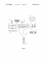
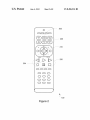
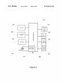
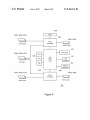
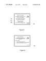
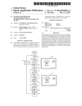
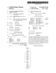
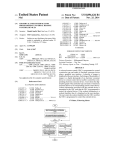
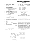
US008456314B2
(12) United States Patent
Arling et al.
(54)
SYSTEM AND METHOD FOR
RECONFIGURATION OF AN
ENTERTAINMENT SYSTEM CONTROLLING
DEVICE
(56)
Patrick H. Hayes, Mission Viejo, CA
(73) Assignee: Universal Electronics Inc., Santa Ana,
CA (US)
Notice:
Subject to any disclaimer, the term of this
patent is extended or adjusted under 35
U.S.C. 154(b) by 778 days.
Jun. 4, 2013
References Cited
U.S. PATENT DOCUMENTS
(75) Inventors: Paul D. Arling, Irvine, CA (US);
(Us)
US 8,456,314 B2
(10) Patent N0.:
(45) Date of Patent:
5,959,751 A
6,784,805 B2
6,910,085 B2
9/1999 Darbee et a1.
8/2004 Harris et a1.
6/2005 Takaku et a1.
6,918,136 B2 *
7/2005
6,930,730 B2
8/2005 MaXon et al.
Shepherd .................... .. 725/141
7,119,710
7,155,305
7,586,398
2002/0194621
B2
10/2006 Hayes et a1.
B2
12/2006 Hayes et a1.
B2
9/2009 Huanget et a1.
A1* 12/2002 Tran et a1. ................... ..
2003/0234737
2004/0004630
2004/0070491
2004/0117843
A1
12/2003 Nelson et a1.
A1
1/2004 Kalva et a1.
A1
4/2004 Huang et a1.
A1* 6/2004 KaraoguZ et a1. ..
2005/0034160 A1*
2/2005
Kim et a1. ..... .
725/139
.. 725/108
725/80
(Continued)
(21) Appl. No.: 12/621,277
FOREIGN PATENT DOCUMENTS
(22)
Filed:
Nov. 18, 2009
(65)
Prior Publication Data
US 2011/0074591A1
(63) Continuation-in-part of application No. 12/569,121,
?led on Sep. 29, 2009, noW Pat. No. 8,243,207.
G08B 1/08
G08B 21/00
G08C 19/06
G08C 19/12
(52)
Primary Examiner * Julie Lieu
(74) Attorney, A gent, or Firm * Greenberg Traurig, LLP
ABSTRACT
An entertainment device is used to notify a user of a change in
(2006.01)
(2006.01)
(2006.01)
(2006.01)
an audio visual entertainment system con?guration in Which
at least one of a plurality devices is connected to the enter
tainment device as an audio and/or visual source and at least
one of the plurality of devices is connected to the entertain
U.s. c1.
USPC ..... .. 340/635; 340/509.1; 340/540; 340/125;
340/131; 340/1324; 725/80; 725/81; 725/85;
725/139; 725/141
(58)
8/2009
7/1994
7/2009
WIPO, International Preliminary Report on Patentability of PCT
Appln. No. US2010/050614, Apr. 3, 2012, 6 pages.
(57)
Int. Cl.
2091246 A2
2275800
2009171232
OTHER PUBLICATIONS
Mar. 31, 2011
Related US. Application Data
(51)
EP
GB
JP
Field of Classi?cation Search
None
See application ?le for complete search history.
ment device as an audio and/ or visual output destination for
the entertainment device and/or to notify a user of a perceived
problem in a con?guration of a controlling device used to
control functional operations of the audio visual entertain
ment system.
19 Claims, 8 Drawing Sheets
US 8,456,314 B2
Page 2
US. PATENT DOCUMENTS
2006/0050142
2007/0052547
2007/0185597
2008/0066123
2008/0186078
A1
A1
A1
A1
A1
3/2006
3/2007
8/2007
3/2008
8/2008
Scott et a1.
Haughawout et a1.
Bejean et a1.
Igoe et a1.
Shintani et a1.
2009/0254966
2010/0287258
2010/0309375
2011/0030016
2011/0106984
A1* 10/2009 Josephs et a1. .............. .. 725/140
A1
11/2010 Takeuchi
A1* 12/2010 Alexander .................. .. 348/570
A1* 2/2011 Pino et a1. ..................... .. 725/80
A1* 5/2011 Tanaka et a1. ................. .. 710/16
* cited by examiner
US. Patent
Jun. 4, 2013
Sheet 1 of8
US 8,456,314 B2
114
8
Figure 1
US. Patent
Jun. 4, 2013
Sheet 2 of8
US 8,456,314 B2
'
202
200
'“ 210
Valuing W». ._ A’,
204
,
@(DCJC)
CDOC)
CDQC)
CDCDQ
CDCDCI)
100
Figure 2
US. Patent
Jun. 4, 2013
Sheet 3 of8
US 8,456,314 B2
300
316
r
310
\\\
‘V/
\\_____,
Key matrix
Transmitter
or
transceiver
circuit
302
User feedback
8
device
8
5
,/j
NV
memory
0
o
o
31 8
E»
304
E
\_\
//
/
z
314
Input/Output
/_,/<
1*
ROM
memory
I
‘SHOCK and
tamer logic
Crystal_|_— I
:1
I‘
//
RAM
memory
=\
Q7
Figure 3
\\
305
US. Patent
Jun. 4, 2013
Sheet 4 0f 8
US 8,456,314 B2
Tunerj/"M
420a, 420b, 420s
i
406
430a, 4230b
processing
Audio
Audio inputs
—@
Audio ouputs
,,
410
Front panel
422a, 422b, 4220
ROM
‘\
402
~_
RAM
AV inputs
"
NV
412
6
:5 3;8
WC
8 g
interface
Q
RAM
,/
414
Network
1/”
connection
400
404
434a, 434!)
4243, 424b, 4240
Video
processing
‘I
42
Video ouputs
Video inputs
1 2
Figure 4
US. Patent
Jun. 4, 2013
Activity setup
Sheet 5 of8
US 8,456,314 B2
530
\
'\e
WELCOME TO ACTlVlTY
SET UP
User activates
;;
desired activity
bum“
x
i
5;
Please select an activity
*
button on your remote control_
502
Display possible
inputs
Press “EXlT" to quit
(source
.
.
devices) for
activity
.
.
.
.
.
.
.
.
.
.
.
.
x
504
532
.
.
.
.
.
.
.
.
.
.
.
.
.
.
.
.
.
.
.
.
.
.
.
.
.
.
.
.
.
WATCH MOVIE SETUP
Allow User to
Step ‘l: Select source
4 ,>
source devices
a ->
‘\\ l
t
Game
:a
3i
536
A V to move
:5
(destination
4 > to include
“SEL" when done
'1
Press
)for
activity
DVD
Biue Ra
-2.5 Mia/".4 4-~——-—'"*—‘
506
.
Display possible
outputs
.
.
.
.
.
.
.
.
.
.
.
.
.
.
.
.
.
.
.
.
.
.
.
.
.
.
.
.
.
.
.
to quit
.
.
.
\\
Allow‘luserto
508
53s
WATCH MOVIE SETUP
select one or more
'
Step 2, select
dismlat'm‘
f§
evices
3?
i
destination
III
510
-> Projector
'5
I
.
__
‘~~t\
select one or more
devices
.
,\
l
.
.
........................................................................................ ..
I _
A Y to move
Ii
4) to include
Configure activity
1;
“SEL” when done
parameters
'5
"“\x
l
Press "EXIT" to quit
512
Display Completion
I.I.:.:.I.2.2.:.2.2.2.I.:.:.I.2.2.:.I.:.:.I.m.2.2.:.I.:.:.I.2.2.:.:.:.:.:.:.:.:.:.:.:.:.
message (with
rem'nder 'fmumple
__
CONGRATULATIONS!
I “Watch Movie” activity setup is complete.
sources or
destinations)
.
“'\,_
_
\
514
I
’
542
_
Because you configured multiple
2; sources, you will be prompted each time
to select which one to use.
To set up another activity, select the activity button
'
on your remote. Else press “EXlT” if done.
Press‘EXlT' to quit
Figure 5
US. Patent
Jun. 4, 2013
Sheet 6 of8
US 8,456,314 B2
Activity button
activated
630
624 \_\
WATCH MOVIE
‘
P
Please select source
f.
ro‘mpt
eel up‘gem?
activity"'3
t
Allow user to
g1
_________________ __
choose
source desired
device
i3
Blue Ray
“
—'>i
i:
A V to move
§I
4b to include
g1
"SEL" when done
Select input
Press ‘EXIT’ to quit
\
608
powered
on?
k
N
610
Request remote to
power on source
device
632
Multiple
estimations‘?
WATCH MOVIE
~
614
.
__
Allow userto
select desired
l
§I
destination device
.
Please select destination
T\/
5
Projector
g1
‘
A V to move
4 > to include
“SEU when done
Press “EXIT” to quit
Request remote to
power on dest.
device
—-----*1
620
Send con?guration
data to remote
Figure 6
US. Patent
Jun. 4, 2013
Sheet 7 of8
US 8,456,314 B2
NNN
v
2N:9“.
US. Patent
Jun. 4, 2013
Sheet 8 of8
US 8,456,314 B2
DEVICE CHANGED
The device connected to input
“DVD" has changed.
802
\
Your remote control set up
may need to be updated.
5;
804
\
"
AYtomove
“
*
,
SELto select j§j
Flg u re 8
EXlTto quit
“\x
\*\
DEVICE PROBLEM?
1T APPEARS THAT YOUR DVD
PLAYER IS NOT RESPONDING AS
EXPECTED.
SUGGESTIONS:
0
Is your remote in "DVD" mode?
;§;
Is there an object between you and the player? ff
0
Does your remote need to be set up?
'
EXIT to quit
\‘k, \
‘
Figure 9
900
US 8,456,314 B2
1
2
A better understanding of the objects, advantages, features,
SYSTEM AND METHOD FOR
RECONFIGURATION OF AN
ENTERTAINMENT SYSTEM CONTROLLING
DEVICE
properties and relationships of the invention Will be obtained
from the folloWing detailed description and accompanying
draWings Which set forth illustrative embodiments and Which
are indicative of the various Ways in Which the principles of
RELATED APPLICATION DATA
the invention may be employed.
This application claims the bene?t of and is a continuation
BRIEF DESCRIPTION OF THE DRAWINGS
in-part ofU.S. application Ser. No. 12/569,121 ?led Sep. 29,
2009.
BACKGROUND
Home entertainment systems in Which multiple media
sources and multiple media rendering devices are coupled
through a central routing device such as an AV receiver are
Well knoWn in the art, as are universal controlling devices
adaptable to issue commands to a multiplicity of appliances
of different manufacture and/or type and Which are frequently
associated With such home entertainment systems. As these
20
For a better understanding of the various aspects of the
invention, reference may be had to preferred embodiments
shoWn in the attached draWings in Which:
FIG. 1 illustrates an exemplary system in Which the meth
ods of the instant invention may be practiced;
FIG. 2 further illustrates an exemplary controlling device
ofthe system of FIG. 1;
FIG. 3 illustrates a block diagram of exemplary compo
nents of the exemplary controlling device of FIG. 2;
FIG. 4 illustrates a block diagram of exemplary compo
home entertainment systems become increasingly complex
due to the proliferation of media formats, appliance types,
nents of an AV receiver of the system of FIG. 1;
etc., the user actions required to con?gure a home entertain
ment system to match a desired activity such as Watching TV
or listening to music have become increasing onerous and
error prone. Various methods have been proposed for auto
process in accordance With the methods of this invention;
FIG. 6 illustrates an exemplary activity sWitching process
in accordance With the methods of this invention;
FIG. 7 illustrates a second exemplary activity con?gura
tion setup process in accordance With the methods of this
FIG. 5 illustrates an exemplary activity con?guration setup
25
mating all or part of these con?guration operations, for
example through use of controlling device based macro
sequences such as described in US. Pat. No. 5,959,751 or
state-based control such as described in US. Pat. No. 6,784,
invention;
FIG. 8 illustrates an exemplary display prompting a user to
30
error When equipment con?gurations or connections are not
recon?gure a controlling device upon changing an appliance
to be controlled; and
FIG. 9 illustrates exemplary help information Which may
as expected, leading only to further user frustration.
be presented to a user When it is detected that an appliance is
805. HoWever, such methods may themselves be subject to
SUMMARY OF THE INVENTION
35
DETAILED DESCRIPTION
This invention relates generally to improved methods for
con?guring a multi-input and/or multi-output home enter
tainment system to match a user’s desired activities. In such
systems, the outputs and inputs of the various components are
generally routed to and sWitched through one central device
40
such as an AV receiver. The inventive methods described
herein comprise a cooperative effort betWeen the AV receiver
and an associated universal controlling device such as a
remote control in Which activation of an activity key or button
on the controlling device results in transmission of a signal to
45
50
the art. In some embodiments AV to receiver 102 may also
include a netWork interface 12Q, for example Ethernet, for
the routing of streaming media input/output from or to other
system may also be initiated as a result of said activity key
activation, either unilaterally by the controlling device or at
the request of the AV receiver. Since the AV receiver has
55
controlling device (by virtue of the AV receiver’s physical
connection to those appliances), and the controlling device in
areas of the home. When included, such a netWork interface
may also be available for Internet access, doWnload of ?rm
Ware updates and/or other data into AV receiver 102, etc.,
again as Well knoWn in the art. Also illustrated is a universal
controlling device 100 Which is capable of transmitting com
mands to the appliances, using any convenient IR, RF, Point
turn has access to appliance command functions not available
to the AV receiver, the cooperative execution of an activity
con?guration request in this manner may result in more reli
of a group of various media source appliances such as for
example a set top box (“STB”) 104, a ?rst DVD player 106, a
second DVD player 108, a game console 110, and a CD
changer 112 are all connected as inputs to anAV receiver 102.
AV receiver 102 in turn functions to sWitch the currently
jector 118, and/or loudspeakers 116; all as is Well knoWn in
receiver’s determination of the current status of connected
access to appliance status information not available to the
Turning noW to FIG. 1, there is illustrated an exemplary
home entertainment system in Which the audio/video outputs
desired input media stream to one or more designated outputs
of AV receiver 102 Which are, in turn, connected to various
audio and/or video rendering devices such as TV 114, pro
the AV receiver to initiate certain previously de?ned con?gu
ration actions, Which actions may be conditioned upon theAV
devices. In addition, certain controlling device command
transmissions to other appliances in the home entertainment
not responding correctly to command requests.
60
to-Point, or netWorked protocol, to cause the appliances to
perform operational functions. While illustrated in the con
able and user-friendly system operation. In addition, since
text of a home entertainment system, it is to be understood
prior art initial user set up of AV receivers is generally GUI
based and includes assignment of user-friendly names to
that appliances controllable by universal controlling device
source and destination appliances (for example, “DVD” in
place of “Video input 3”), a user’s initial speci?cation of
desired activity con?gurations may be facilitated by the use of
these features When con?guring activities.
100 may include, but need not be limited to, televisions,
VCRs, DVRs, DVD players, cable or satellite converter set
65
top boxes (“STBs”), ampli?ers, AV receivers, CD players,
game consoles, home lighting, drapery, fans, HVAC systems,
thermostats, personal computers, etc. In a preferred embodi
US 8,456,314 B2
3
4
ment, controlling device 100 supports bidirectional commu
device operating program”) may be executed. For example,
nication 130 With AV receiver 102 via any convenient IR or
When a function key is actuated on the controlling device 100,
the controlling device 100 may retrieve from the command
data stored in memory 304, 305, 306 a command value and
RF protocol.
In an exemplary embodiment, controlling device 100 may
be further adapted to function in cooperation WithAV receiver
102 to con?gure the illustrative entertainment system in
control protocol corresponding to the actuated function key
and, Where necessary, current device mode and transmit that
command to an intended target appliance, e.g., STE 104, in a
accordance With a user’s desired activities. To this end, as
format recogniZable by that appliance to thereby control one
illustrated in FIG. 2, an exemplary controlling device may be
provisioned With a series of activity selection keys or buttons
200 With designations such as, for example, “Watch TV”,
“Watch a Movie”, “Listen to Music”, “Play a Game”, etc.
Activation of such an activity selection key may cause AV
receiver 102 and/or controlling device 100 to cooperatively
place the exemplary home entertainment system into a user
speci?ed state Which has been associated With that activity, as
Will be described in further detail hereafter.
Turning noW to FIG. 3, for use in commanding the func
tional operations of one or more appliances, the controlling
device 100 may include, as needed for a particular applica
tion, a processor 300 coupled to a ROM memory 304, a RAM
or more functional operations of that appliance. It Will be
appreciated that the operating program can be used not only to
cause the transmission of commands and/ or data to the appli
ances, but also to perform local operations. While not limit
ing, local operations that may be performed by the controlling
device 100 may include displaying information/data, favorite
channel setup, macro key setup, function key relocation, etc.
Examples of local operations can be found in US. Pat. Nos.
5,481,256, 5,959,751, and 6,014,092.
20
appliance by its make, and/or model, and/or type. Such data
alloWs the controlling device 100 to identify the appropriate
memory 305, a key matrix 316 (e.g., hard keys, soft keys such
as a touch sensitive surface overlaid on a liquid crystal (LCD),
and/ or an electroluminescent (EL) display), transmission cir
cuit(s) and/or transceiver circuits) 310 (e.g., IR and/ or RF), a
non-volatile read/Write memory 306, a means 302 to provide
feedback to the user (e.g., one or more LEDs, display,
speaker, and/or the like), an input/output port 318 such as a
25
doWnloaded into controlling device 100 as part of the setup
process, or a combination thereof. The library of command
30
of the memories 304, 305, 306 may include executable
instructions (collectively, the controlling device program
memory) that are intended to be executed by the processor
300 to control the operation of the remote control 100, as Well
command data set Within a library of command data that is to
be used to transmit recogniZable commands in formats appro
priate for such identi?ed appliances. Such a library of com
mand data may be preprogrammed in controlling device 100,
serial interface, USB port, modem, Zigbee, WiFi, or Blue
tooth transceiver, etc., and clock and timer logic 312 With
associated crystal or resonator 314.
As Will be understood by those skilled in the art, some or all
For selecting sets of command data to be associated With
the appliances to be controlled data may be provided to con
trolling device 100 that serves to identify each intended target
35
data may represent a plurality of controllable appliances of
different types and manufacture, a plurality of controllable
appliances of the same type but different manufacture, a
plurality of appliances of the same manufacture but different
type or model, etc., or any combination thereof as appropriate
for a given embodiment. In certain embodiments, such data
used to identify an appropriate command data set may take
as data Which serves to de?ne to the operational softWare the
the form of a numeric setup code (obtained, for example, from
necessary control protocols and command values for use in
a printed list of manufacturer names and/or models With
transmitting command signals to controllable appliances
corresponding code numbers, from a support Web site, etc.)
(collectively, the command data). In this manner, the proces
Which may be entered via activation of those keys that are also
sor 300 may be programmed to control the various electronic
components Within the remote control 100, e.g., to monitor
the key matrix 316, to cause the transmission of signals, etc.
The non-volatile read/Write memory 306, for example an
40
used to cause the transmission of commands to an appliance,
45
preferably the keys that are labeled With numerals.
Alternative device setup procedures knoWn in the art
include scanning bar codes, RFTD tags, or other indicia;
sequentially transmitting a predetermined command in dif
ferent formats until a target appliance response is detected;
interaction With a Web site culminating in doWnloading of
command data and/or setup codes to the controlling device,
etc. Further, in embodiments such as that illustrated in FIG. 1,
set up of a controlling device 100 may be performed interac
50
tively in conjunction WithAV receiver 102, using a connected
EEPROM, battery-backed up RAM, FLASH, Smart Card,
memory stick, or the like, may additionally be provided to
store setup data and parameters as necessary. While the
memory 304 is illustrated and described as a ROM memory,
memory 304 can also be comprised of any type of readable
media, such as ROM, FLASH, EEPROM, or the like. Prefer
ably, the memories 304 and 305 are non-volatile or battery
backed such that data is not required to be reloaded after
battery changes. In addition, the memories 304, 305 and 306
device such as TV 114 for GUI display and a database of
codes and/or brand and model information stored locally on
may take the form of a chip, a hard disk, a magnetic disk, an
AV receiver 102 or located remotely on a PC or Web server
optical disk, and/or the like. Still further, it Will be appreciated
that some or all of the illustrated memory devices may be
55
and accessed via netWork connection 120. Since such meth
ods for setting up a controlling device to command the opera
physically combined (for example, a single FLASH memory
may be logically partitioned into different portions to support
the functionality of memories 304 and 306 respectively),
tion of speci?c home appliances are Well-known, these Will
not be described in greater detail herein. Nevertheless, for
and/or may be physically, incorporated Within the same IC
chip as the microprocessor 300 (a so called “microcontrol
ler”) and, as such, they are shoWn separately in FIG. 3 only for
reader may turn, for example, to US. Pat. Nos. 4,959,810,
5,614,906, or 6,225,938 or to pending US. patent application
additional information pertaining to setup procedures, the
60
Ser. No. 11/915,562, all oflike assignee and all incorporated
herein by reference in their entirety.
the sake of clarity.
To cause the controlling device 100 to perform an action,
the controlling device 100 is adapted to be responsive to
events, such as a sensed user interaction With the key matrix
316, etc. In response to an event, appropriate instructions
Within the program memory (hereafter the “controlling
65
With reference to FIG. 4, an exemplary AV receiver 102
may include, as needed for a particular application, a control
processor 400 coupled to a memory 402 Which may comprise
any combination of ROM, RAM, and/or non-volatile read
Write memory; video and audio processing sections 404, 406;
US 8,456,314 B2
5
6
a tuner 408 for reception of radio broadcast channels; a front
panel 410 including user controls and/or a display; a remote
navigation keys 210 of controlling device 100 to select a
control interface 412 for communicating With a controlling
device (eg 100); a netWork interface 414 for communication
With a local and/or Wide area network; audio inputs 42011
be appropriate for a particular embodiment. Upon entering
activity setup mode, the AV receiver operating program may
menu item displayed on TV 114, or such other action as may
display an exemplary initial status message 530 on TV 114
prompting the user to select an activity to con?gure. The AV
receiver operating program thereafter Waits at step 502 for
user input, i.e. activation of one of the activity buttons 200 of
controlling device 100. In the illustrated example, the to user
may select button 202 labeled “Watch a Movie”, resulting in
through 4200; video inputs 42411 through 4240; AV inputs
42211 through 4220; audio outputs 430a, 4301); and video
outputs 434a and 43419. As Will be appreciated, audio and
video inputs and outputs (Which may be more or less in
number than illustrated) may comprise analog or digital sig
CODECS, format converters, etc., all as necessary to imple
communication by the controlling device 100 of an appropri
ate key command value to AV receiver 102. Upon receipt of
the “Watch a Movie” activity command, at step 504 the AV
receiver operating program may display a listing 532 of avail
ment the input/ output sWitching and routing functionality. It
able source devices that are knoWn to be connected to inputs
Will be further appreciated that the functionality of video and
audio processing blocks 404 and 408 may be implemented in
separate components such as a specialiZed digital signal pro
ciated that the earlier-mentioned initial setup procedures of
nals and exemplary AV receiver 1 02 may be provisioned With
analog-to-digital (ADC) converters, digital-to-analog (DAC)
converters, video decoders, HDMI encoder/decoders,
cessors (DSP), may be implemented as part of control pro
cessor 400, or any combination thereof, and that portions of
422, 424 of AV receiver 102. In this context it Will be appre
20
AV receiver may include user labeling/identi?cation of the
devices connected to the various inputs together With a selec
tion of compatible command data sets Within universal con
memory 402 may be allocated to or associated With audio and
trolling device 100, and the resulting user friendly labels such
video processing blocks 404,408.
as “DVD player”, “Projector”, etc. may be used thereafter in
the generation of displays such as that illustrated at 532.
It Will also be appreciated that some or all of the memory
elements 402 may take the form of a chip, a hard disk, a
magnetic disk, an optical disk, FLASH memory, and/or the
like, and that all or portion of the memory 402 may be physi
cally incorporated Within the same IC chip as the control
Additionally, the displayed listing may be further tailored by
25
the speci?ed activityifor example, for the presently illus
processor 400 and/or audio or video processing blocks 404,
406 and, as such, memory 402 is shoWn separately in FIG. 4
only for the sake of clarity.
the AV receiver operating program to include only those
currently-con?gured devices knoWn to be compatible With
30
trated “Watch a Movie” activity devices Which are incapable
of sourcing a video stream, such as CD player 112 or tuner
408 may be omitted from the list presented to the user. At step
As Will be understood by those skilled in the art, some or all
506, the user may employ navigation keys 210 of controlling
of the memory 402 may include executable instructions that
device 100 to move a cursor 536 and select desired source
device(s). One or more source devices may be selected, as
are intended to be executed by the processor 400 to control the
operation of the AV receiver 102 (hereafter, the “AV receiver
operating program”). In this manner, the processor 400 may
be programmed to control the various electronic components
Within theAV receiver, e.g., to monitor the front panel 410 and
indicated for example by indicia 534. In the event more than
35
described in further detail hereafter in conjunction With FIG.
6.
or remote control interface 412, to cause the routing of video
and/ or audio signals betWeen the various inputs and outputs,
to control selection of radio broadcast channel by tuner 408,
to control volume and equalization settings of audio outputs
430a and 430b, etc. Further, the AV receiver operating pro
gram, in conjunction With video processing block 404, may
provide GUT-based setup menus for AV receiver functions
such as input and output assignments, levels, balances, equal
40
above. Once again, the list of devices may be tailored by the
AV receiver operating program to include, in this case, only
those currently-con?gured devices knoWn to be capable of
45
example TV 114. Since such GUI-based AV receiver setup is
Well knoWn in the art, for the sake of brevity it Will not be
described further herein, hoWever if greater detail is desired
50
reader may reference, for example, a document such as the
Denon AV Surround Receiver STR-DA5500ES OWner’s
sequence of keypresses on controlling device 100, use of
key that Was activated at the start of the con?guration process.
Thereafter, the AV receiver operating program may display a
completion message 540, including in this example a
60
referenced Denon STR-DA5500ES User’s Manual, a user
may Wish to con?gure the functionality of the activity buttons
200 of controlling device 100. To this end, she may place the
AV receiver into an activity setup mode via, for example by a
may also be presented to the user in certain embodiments, for
example, selection of a destination for audio output. Once all
user selections have been made, at step 512 the activity con
?guration parameters may be ?naliZed and stored in AV
receiver memory 402 for future use in con?guring the home
received key command value corresponding to the activity
55
de?ne and subsequently execute user-desired con?guration
of the home entertainment system in accordance With various
activities.
With reference to FIG. 5, after completing the initial set up
of AV receiver 102, for example as described in the above
rendering the designated input media stream(s). Although not
shoWn, it Will be appreciated that other con?guration options
entertainment system When the indicated activity is called for,
e.g., the ?nal con?guration is stored and associated With the
Manual (D&M Holdings Inc. publication number 5411
10255 000D).
In addition, in an exemplary embodiment described herein
the AV receiver operating program may include programming
Which functions in cooperation With controlling device 100 to
Upon completion of source device selection, at step 508 a
list 538 of possible destination devices may be displayed for
user selection at step 510 in a similar manner to that described
iZation, etc., via a connected video monitor device such as for
regarding such features and functionality the interested
one source device is designated, the user may be prompted at
activity execution time to select the desired source, as Will be
65
reminder 542 that ?nal source selection Will be required at
execution time. At step 516, the user indicates Whether she
Wishes to set up another activity, in Which case processing
returns to initial step 502. If not, activity setup is complete and
the AV receiver operating program exits setup mode and
returns to normal operation.
The execution of an exemplary activity con?guration
request Will noW be discussed in conjunction With FIG. 6.
Upon actuation of an activity button on controlling device
100, for example 202 “Watch a Movie” and receipt of the
US 8,456,314 B2
7
8
resulting appropriate key command value communication by
a result of receipt of the aforementioned requests to poWer-on
a device and, as such, step 622 can be skipped if this data has
AV receiver 102, assuming the AV receiver operating pro
gram is in the normal operation state (i.e. not in setup mode as
already been provided to the controlling device by the AV
described previously), at step 602 the AV receiver operating
program ?rst determines if the activity by the key command
value received from the controlling device has in fact been
receiver.
Although not illustrated in the example of FIG. 6, in certain
embodiments additional appliance con?guration may be ini
tiated by the AV receiver operating program and/ or the con
con?gured. If not, at step 624 an error message is displayed,
for example on TV 114, prompting the user to ?rst con?gure
trolling device operating program and performed by control
that activity, and the activity request is ignored. If the activity
ling device 100, for example issuance of commands for
has been con?gured, at step 604 the AV receiver operating
program next determines from the con?guration associated
With the received key command value if multiple sources
adjustment of video aspect ratio or picture settings to opti
selection of an appropriate input on TV 114 or projector 118,
miZe presentation of the selected source material, etc. Also,
additional actions may be initiated by the AV receiver oper
Were con?gured. If so, at step 606 the options are displayed as
illustrated at 630 and the user is prompted to select a desired
ating program and/or the controlling device operating pro
source device, for example, by using the navigation and selec
tion keys of the controlling device to highlight and select the
gram With respect to appliances not participating in an activ
ity. For example, initiation of a “Listen to Music” activity may
cause the controlling device itself, or result in the issuance of
desired source device. As Will be appreciated, if only one
source device Was con?gured at setup time, this step may be
skipped. Once a source device has been designated, at step
608 the AV receiver operating program selects the audio,
video and/orAV inputs associated With the designated source
device. At step 610, the AV receiver operating program deter
requests to controlling device, to poWer off video display
20
described above, in certain embodiments the activation of an
activity selection button 200 may also invoke a conventional
controlling device-based macro command sequence as is
mines if the selected source device is poWered on, for
example by detecting presence or absence of audio/video
signal, sensing HDMI status, etc. as appropriate for the device
connection in question. Alternatives such as poWer sensing,
etc. may also be available in certain embodiments. If the
selected source device is not poWered on, in a preferred
embodiment at step 612 a request may issued to controlling
device 100 via bidirectional communication link 130 to trans
mit a “poWer on” command to the source appliance. As Will be
knoWn in the art and described, for example, in the previously
25
levels, control drapes, etc. to create an environment suitable
for the commanded activity, as Well as to perform additional
entertainment appliance con?guration functions if desired.
30
detection of AV signals from an auxiliary output of a render
ing device, poWer sensing, etc. may also be available in cer
tain embodiments. If the selected destination device is not
poWered on, in a preferred embodiment at step 620 a request
may be issued to controlling device 100 via bidirectional
as an alternative to the AV receiver GUI based setup previ
ously described above in conjunction With FIG. 5. Such a PC
based setup option may comprise a locally installed applica
35
illustrated in FIG. 7, the PC based setup application may
menus 702, 704 from Which the various con?guration options
may be selected. In the illustrative example, separate panels
40
outputs of an activity and selection and assignment of appli
respectively. As Will be understood by those of skill in the art,
45
cation. Drop doWn menu panel 706 may offer AV receiver
50
repetition, these Will not be repeated. In the illustrated exem
plary embodiment, drop doWn menu panel 708 alloWs the
controlling device key groups for volume control, channel
changing and transport to be pre-con?gured as appropriate.
appliances 104, 106, 108 have been pre-con?gured as the
As an aid to the user, in some embodiments an image 712 of
60
controlling device 100 may be displayed With the affected key
group highlightedifor example, When the drop doWn menu
710 for transport keys is active, this group of keys 714 may be
highlighted in displayed image 712. In some embodiments,
default key assignments may be dynamically established and
displayed in panel 708 by the PC application based upon the
65
audio output for an activity is assigned to a set of speakers 718
connected to the output ofAV receiver, the default volume key
assignment 722 may be the AV receiver, Whereas if the audio
output for the same activity Were to be assigned to the TV
55
Movie” activity mode, in the event that multiple possible
sources (or destinations) are possible in the “Watch a Movie”
current activity con?guration settings. By Way of example, if
bidirectional communication link 130 from the AV receiver
operating program to controlling device 100 to cause the
controlling device to con?gure itself to match the activity and
selected source and destination appliances. It Will also be
in general tWo drop-doWn menus such as 710 and 716 may not
be active the same time, they are hoWever illustrated as such
in FIG. 7 to assist in a better understanding of the PC appli
related activity con?guration choices similar to those previ
ously described in conjunction With FIG. 5, and, to avoid
transmit commands in a format compatible With Whichever of
activity mode (Which does not alloW for a pre-con?guration
of the keys of the controlling device to a particular appliance),
at step 622 data indicative of the appliances to be controlled in
the currently selected activity mode may be transferred over
706 and 708 alloW selection and con?guration of sources and
ance/ controlling device key functionality for that activity,
ling device, e.g., transport keys 240 may be con?gured to
media source Within the remote control When in the “Watch a
tion program, a Web application, or a combination thereof. As
comprise a GUI 700 Which offers a series of drop-doWn
communication link 130 to transmit a “poWer on” command
to the destination appliance.
While initiation of a “Watch a Movie” activity via key 202
may result in automatic con?guration of keys of the control
Turning noW to FIG. 7, in an alternative embodiment, a PC
based activity setup application may be offered in place of or
destinations Were con?gured. If so, at step 616 the options are
displayed as illustrated at 632 and the user prompted to select
a desired destination device as described above. Again, if only
one destination device Was con?gured at setup time, this step
may be skipped. At step 618, the AV receiver operating pro
gram determines if the selected destination device is poWered
on, for example by sensing HDMI status. Alternatives such as
referenced U.S. Pat. No. 5,959,751. Such macro sequences
may be programmed by a user to, for example, adjust lighting
appreciated, such a request Would include data that functions
to indicate to the controlling device 100 the intended target
appliance for the “poWer on” command. Thereafter, at step
614 the AV receiver operating program determines if multiple
devices such as TV 114 or projector 118.
In addition to the interactions With AV receiver 102
appreciated that keys of the controlling device 100 may, in
device 720, the default volume control key assignment may
Whole or in part, be matched to an intended target appliance as
be the TV device. In this context, it Will be appreciated that in
US 8,456,314 B2
10
player input to discern if a corresponding change in AV input
data has occurred, for example an audio component has
certain embodiments provision may be made for uploading
existing activity con?guration settings from an AV receiver
into the PC application for editing, by a user, in Which
instance the existing values may become the default settings.
become present in a digital data stream Where there Was none
before. Alternatively, the operating softWare may monitor the
reported user activity on controlling device 100 for patterns
indicative of a problem. For example, repeated actuation of
It Will be appreciated that in instances Where more than one
input or output device has been selected for an activity and the
?nal choice is to be made at execution time as previously
described, some or all of the drop doWn menu items in key
con?guration panel 708 may be omitted or replaced With
generic designators such as “Audio destination device” or
“Video source”, etc.
Once all aspects of the activities match a user’s require
ments, the user may cause the resulting con?guration data to
be doWnloaded into the exemplary AV receiver 102, for
example via netWork interface 120 if both the PC and AV
the “Play” key 204 Within a short space of time may indicate
that an expected appliance response has not occurred. In
either case, a message such as illustrated in FIG. 9 may be
presented on a connected display such as TV 114 to assist the
user in resolving the problem.
While various concepts have been described in detail, it
Will be appreciated by those skilled in the art that various
modi?cations and alternatives to those concepts could be
developed in light of the overall teachings of the disclosure.
receiver are connected to the same network. Alternatively,
con?guration data may be uploaded to a remote server for
subsequent doWnload to the AV receiver, copied to a memory
stick or smart card for physical transfer, etc. Additionally,
controlling device 100 may be coupled to the PC and become
the repository for some or all of the con?guration data, either
for later transfer to AV receiver 102, or for direct action by
controlling device 100.
In certain embodiments, the operating softWare of AV
receiver 102 may be adapted to detect changes in connected
For example, While described in the context of anAV receiver
acting a central sWitching point for content streams in a home
20
25
entertainment system, it Will be appreciated that any other
suitably equipped device, for example an advanced cable or
satellite STB, a personal computer, etc., may be substituted
for an AV receiver in the practice of the instant invention.
Further, While a preferred embodiment described above com
prises a controlling device capable of bidirectional commu
nication With an AV receiver or other central sWitching
appliances, for example by monitoring disconnection/recon
device, it Will be appreciate that many of the steps of the
nection of interface cabling, by observing changes in source
inventive methods may also be practiced in a system com
or sink equipment identity or capability data reported over an
prising a controlling device Which is in unidirectional (in
Ward) communication With the central sWitching device, in
HDMI or other digital connection, by noting an alteration in
the bit rate or format of an input data stream, by detecting
30
connection of an interface cable or presence of a neW audio/
video signal at a previously unused AV receiver input, or any
other appropriate method. In such instances, the operating
contemplated that, in lieu of receiving appliance indicating
softWare of AV receiver 102 may cause to be displayed on a
connected appliance, for example TV 144, a reminder mes
sage to the user that controlling device 100 may require to be
35
set up to operate the neWly-con?gured appliance. Display of
such a reminder message may be immediate upon detection
of the change, may occur upon receipt of the next user com
mand from controlling device 100, or may be deferred until
the neWly added or changed appliance is selected as an input
or output, either directly or as a participant in an activity. As
illustrated in FIG. 8, such a reminder message 800 may offer
a choice 802 of immediately entering an interactive setup
mode in Which a database of command data sets and/ or brand
and model information stored locally on AV receiver or
45
receiver into that activity mode. Activation of a device mode
key in this manner may also be used to cause the transmission
of data to the AV receiver to thereby cause the AV receiver to
select one of multiple possible sources and/or destinations in
lieu of the menu navigation/selection method that Was also
previously described.
50
Still further, While described in the context of functional
modules and illustrated using block diagram format, it is to be
In a further embodiment, the operating softWare of control
ling device 100 may be adapted to alWays echo certain com
mands to AV receiver 104, that is, upon actuation of certain
understood that, unless otherWise stated to the contrary, one
or more of the described functions and/or features may be
functional keys, controlling device 100 may sequentially
integrated in a single physical device and/ or a softWare mod
55
thereafter the appropriate command data in the format recog
ule, or one or more functions and/or features may be imple
mented in separate physical devices or softWare modules. It
Will also be appreciated that a detailed discussion of the actual
implementation of each module is not necessary for an
niZable by the current target appliance. Using the received
keypress noti?cation data, the operating softWare of AV
receiver 104 may be adapted to monitor the AV inputs and
outputs for the expected result of a user appliance command.
sources and/ or destination appliances in a give activity mode,
for example by activating the desired mode key(s) Within a
predetermined period of time after activation of the activity
mode key When used to place the controlling device and AV
into controlling device 100; or display of the reminder may be
transmit ?rst a keypress noti?cation to AV receiver 104 and
data from the AV receiver, the controlling device may be
programmed Whereby activation of a particular device mode
key, e.g., cable, DVD, game player, etc., is used by the con
trolling device to con?gure groups of keys of the controlling
device to communicate commands to a one of plural possible
40
located remotely on a PC or Web server may be searched and
an appropriate command data set identi?ed to or doWnloaded
cancelled 806 or deferred 804.
Which case certain controlling device actions may be initiated
autonomously as macro sequences using, for example, dis
crete appliance commands as are knoW in the art. Further
more, in the case of a unidirectional controlling device, it is
enabling understanding of the invention. Rather, the actual
If the expected result does not occur, an error message may be
implementation of such modules Would be Well Within the
routine skill of an engineer, given the disclosure herein of the
displayed to prompt the user to retry the command, check the
attributes, functionality, and inter-relationship of the various
operating mode of controlling device 100, etc. For example, if
functional modules in the system. Therefore, a person skilled
the currently selected activity is “Watch a Movie” and the
operating softWare of AV receiver 104 is noti?ed by control
ling device 100 that the “Play” key 204 has been actuated, the
operating softWare of AV receiver 104 may inspect the DVD
60
in the art, applying ordinary skill, Will be able to practice the
65
invention set forth in the claims Without undue experimenta
tion. It Will be additionally appreciated that the particular
concepts disclosed are meant to be illustrative only and not
US 8,456,314 B2
11
12
limiting as to the scope of the invention Which is to be given
connected to the entertainment device as an audio and/or
the full breadth of the appended claims and any equivalents
visual source and at least one of the plurality of devices is
thereof.
All patents cited Within this document are hereby incorpo
visual output destination for the entertainment device, the
rated by reference in their entirety.
method comprising:
connected to the entertainment device as an audio and/or
What is claimed is:
1. A method for using an entertainment device to notify a
causing the entertainment device to determine if there is a
user of a change in an audio visual entertainment system
con?guration in Which at least one of a plurality devices is
nected to the entertainment device; and
in response to the entertainment device determining that
change in one or more of the plurality of devices con
connected to the entertainment device as an audio and/or 10
visual source and at least one of the plurality of devices is
there is a change in one or more of the plurality of
devices connected to the entertainment device, using the
connected to the entertainment device as an audio and/or
entertainment device to cause a display by at least one of
visual output destination for the entertainment device, the
the plurality of devices connected to the entertainment
method comprising:
device as a visual output destination for the entertain
ment device a message that serves to notify the user of
causing the entertainment device to determine if there is a
change in one or more of the plurality of devices con
nected to the entertainment device; and
in response to the entertainment device determining that
the change in the audio visual entertainment system
there is a change in one or more of the plurality of
Wherein the entertainment device Waits for the entertain
ment device to be placed into a mode in Which a changed
devices connected to the entertainment device, using the
con?guration;
20
one or more of the plurality of devices connected to the
entertainment device is to be used as an audio and/or
visual source or as an audio and/or visual output desti
entertainment device to cause a display by at least one of
the plurality of devices connected to the entertainment
device as a visual output destination for the entertain
ment device a message that serves to notify the user of
the change in the audio visual entertainment system
25
con?guration;
Wherein the message comprises a user interface element
selectable to place a remote control device into a mode
for con?guring the remote control device to command
functional operations of one or more of the plurality of
devices connected to the entertainment device.
2. The method as recited in claim 1, Wherein the entertain
ment device determines that there is a change in one or more
of the plurality of devices connected to the entertainment
device in response to the entertainment device detecting a
30
control before causing the message to be displayed.
35
response to the entertainment device determining that there is
a change in one or more of the plurality of devices connected
to the entertainment device.
4. The method as recited in claim 1, Wherein the entertain
change in one or more cables connected to the entertainment
device.
10. The method as recited in claim 8, Wherein the enter
ment device Waits for the receipt of a command from a remote
3. The method as recited in claim 1, Wherein the entertain
ment device causes the message to be displayed in immediate
nation for the entertainment device before causing the
message to be displayed.
9. The method as recited in claim 8, Wherein, the entertain
tainment device determines that there is a change in one or
more of the plurality of devices connected to the entertain
ment device in response to the entertainment device detecting
a change in one or more input signals being provided to the
entertainment device.
11. The method as recited in claim 10, Wherein the enter
ment device determines that there is a change in one or more
tainment device monitors the one or more input signals for a
change in transmission bit rates to determine if there is a
change in one or more of the plurality of device connected to
of the plurality of devices connected to the entertainment
device in response to the entertainment device detecting a
the entertainment device.
12. The method as recited in claim 8, Wherein the enter
40
change in one or more cables connected to the entertainment
device.
5. The method as recited in claim 1, Wherein the entertain
45
tainment device determines that there is a change in one or
more of the plurality of devices connected to the entertain
ment device in response to the entertainment device detecting
ment device determines that there is a change in one or more
a neW input signal at one or more inputs of the entertainment
of the plurality of devices connected to the entertainment
device in response to the entertainment device detecting a
change in one or more input signals being provided to the
entertainment device.
6. The method as recited in claim 1, Wherein the entertain
device.
13. The method as recited in claim 8, Wherein the enter
50
tainment device determines that there is a change in one or
more of the plurality of devices connected to the entertain
ment device in response to the entertainment device detecting
a change in identi?cations provided to the entertainment
device from the plurality of devices connected to entertain
55
ment device.
14. The method as recited in claim 8, Wherein the enter
tainment device determines that there is a change in one or
ment device determines that there is a change in one or more
of the plurality of devices connected to the entertainment
device in response to the entertainment device detecting a
neW input signal at one or more inputs of the entertainment
device.
7. The method as recited in claim 1, Wherein the entertain
more of the plurality of devices connected to the entertain
ment device in response to the entertainment device detecting
ment device determines that there is a change in one or more
of the plurality of devices connected to the entertainment
device in response to the entertainment device detecting a
60
change in identi?cations provided to the entertainment device
from the plurality of devices connected to entertainment
device.
8. A method for using an entertainment device to notify a
user of a change in an audio visual entertainment system
con?guration in Which at least one of a plurality devices is
65
a change in capabilities provided to the entertainment device
from the plurality of devices connected to entertainment
device.
15. A method for using an entertainment device to notify a
user of a change in an audio visual entertainment system
con?guration in Which at least one of a plurality devices is
connected to the entertainment device as an audio and/or
visual source and at least one of the plurality of devices is
US 8,456,314 B2
13
14
connected to the entertainment device as an audio and/or
entertainment system in Which at least one of a plurality
devices is connected to the entertainment device as an audio
and/or visual source and at least one of the plurality of devices
is connected to the entertainment device as an audio and/or
visual output destination for the entertainment device, the
method comprising:
causing the entertainment device to determine if there is a
visual output destination for the entertainment device, the
change in one or more of the plurality of devices con
method comprising:
nected to the entertainment device; and
in response to the entertainment device determining that
receiving by the entertainment device a signal from the
controlling device having data indicative of a command
there is a change in one or more of the plurality of
to have one or more of the plurality of devices connected
devices connected to the entertainment device, using the
to the entertainment device perform a functional opera
entertainment device to cause a display by at least one of
tion Wherein performance of the functional operation is
detectable by the entertainment device; and
the plurality of devices connected to the entertainment
device as a visual output destination for the entertain
ment device a message that serves to notify the user of
in response to the entertainment device failing to detect
performance of the functional operation after receipt of
the change in the audio visual entertainment system
the signal, using the entertainment device to cause a
display by at least one of the plurality of devices con
con?guration;
Wherein the entertainment device determines that there is a
change in one or more of the plurality of devices con
nected to the entertainment device in response to the
entertainment device detecting a change in one or more
input signals being provided to the entertainment device
nected to the entertainment device as a visual output
destination for the entertainment device a message that
20
tainment device monitors at least one of inputs and out
puts of the entertainment device associated With the one
or more of the plurality of devices connected to the
and Wherein the entertainment device monitors the one
or more input signals for a change in transmission bit
rates to determine if there is a change in one or more of
the plurality of device connected to the entertainment
device.
16. A method for using an entertainment device to notify a
user of a change in an audio visual entertainment system
con?guration in Which at least one of a plurality devices is
connected to the entertainment device as an audio and/or
visual source and at least one of the plurality of devices is
connected to the entertainment device as an audio and/or
entertainment device as an audio and/ or visual source to
25
mand to have one or more of the plurality of devices con
nected to the entertainment device perform a functional
operation comprises a command to control playing of media
30
causing the entertainment device to determine if there is a
35
there is a change in one or more of the plurality of
visual output destination for the entertainment device, the
devices connected to the entertainment device, using the
40
device as a visual output destination for the entertain
ment device a message that serves to notify the user of
to have one or more of the plurality of devices connected
to the entertainment device perform a functional opera
the change in the audio visual entertainment system
45
tion; and
in response to the entertainment device receiving the signal
from the controlling device a predetermined number of
times Within a predetermined period of time, using the
Wherein the entertainment device determines that there is a
change in one or more of the plurality of devices con
nected to the entertainment device in response to the
entertainment device to cause a display by at least one of
entertainment device detecting a change in capabilities
to entertainment device.
17. A method for using an entertainment device to notify a
user of a perceived problem in a con?guration of a controlling
device used to control functional operations of an audio visual
method comprising:
receiving by the entertainment device a signal from the
controlling device having data indicative of a command
the plurality of devices connected to the entertainment
to perform a functional operation provided to the enter
tainment device from the plurality of devices connected
19. A method for using an entertainment device to notify a
user of a perceived problem in a con?guration of a controlling
device used to control functional operations of an audio visual
entertainment system in Which at least one of a plurality
devices is connected to the entertainment device as an audio
and/or visual source and at least one of the plurality of devices
is connected to the entertainment device as an audio and/or
nected to the entertainment device; and
in response to the entertainment device determining that
con?guration;
by one or more of the plurality of devices connected to the
entertainment device as an audio and/or visual source.
method comprising:
entertainment device to cause a display by at least one of
detect performance of the functional operation.
18. The method as recited in claim 12, Wherein the com
visual output destination for the entertainment device, the
change in one or more of the plurality of devices con
serves to notify the user of the perceived problem in the
con?guration of a controlling device, Wherein the enter
50
the plurality of devices connected to the entertainment
device as a visual output destination for the entertain
ment device a message that serves to notify the user of
the perceived problem in the con?guration of a control
ling device.