1
Lexium Controller
User’s manual
Retain for future use
30072 - 452 - 88
Modbus
Contents
Important information _________________________________________________________________________________________ 4
Documentation structure_______________________________________________________________________________________ 5
Introduction _________________________________________________________________________________________________ 6
Presentation _____________________________________________________________________________________________ 6
Connection to the bus_________________________________________________________________________________________ 7
Connecting the Modbus RJ45 connector or graphic display terminal__________________________________________________ 7
Connecting to the Lexium Controller __________________________________________________________________________ 7
Wiring recommendations ___________________________________________________________________________________ 7
RS485 standard __________________________________________________________________________________________ 7
Modbus standard schematic_________________________________________________________________________________ 8
Connecting via RJ45 wiring system ___________________________________________________________________________ 9
Connecting via junction boxes ______________________________________________________________________________ 11
Connecting on screw terminals______________________________________________________________________________ 13
Configuration ______________________________________________________________________________________________ 14
Configuring the Modbus network ____________________________________________________________________________ 14
Diagnostics ________________________________________________________________________________________________ 16
Modbus LEDs ___________________________________________________________________________________________ 16
Communication management and communication interruptions ____________________________________________________ 16
Modbus protocol ____________________________________________________________________________________________
RTU mode _____________________________________________________________________________________________
Principle _______________________________________________________________________________________________
Addresses______________________________________________________________________________________________
Modbus functions ________________________________________________________________________________________
Read N output words: function 3 ____________________________________________________________________________
Write one output word: function 6 ____________________________________________________________________________
Diagnostics: function 8 ____________________________________________________________________________________
Write N output words: function 16 (16#10) _____________________________________________________________________
Identification: function 43 (16#2B) ___________________________________________________________________________
Exception responses _____________________________________________________________________________________
Read non-existent or protected parameters ____________________________________________________________________
17
17
17
17
18
18
19
19
20
21
22
22
While every precaution has been taken in the preparation of this document,
Schneider Electric assumes no liability for any omissions or errors it may contain,
nor for any damages resulting from the application or use of the information herein.
The products and options described in this document may be changed or modified at
any time, either from a technical point of view or in the way they are operated. Their
description can in no way be considered contractual.
3
Important information
PLEASE NOTE
Please read these instructions carefully and examine the equipment in order to familiarize yourself with the device before installing,
operating or carrying out any maintenance work on it.
The following special messages that you will come across in this document or on the device are designed to warn you about potential risks
or draw your attention to information that will clarify or simplify a procedure.
The addition of this symbol to a "Danger" or "Warning" safety label indicates the presence of an electrical hazard that will
result in injury if the instructions are not followed.
This is a safety warning symbol. It warns you of potential risks of injury. You must comply with all safety messages that
follow this symbol in order to avoid any risk of injury or death.
DANGER
DANGER indicates an imminently hazardous situation which, if not avoided, will result in death, serious injury or equipment
damage.
WARNING
WARNING indicates a potentially hazardous situation which, if not avoided, can result in death, serious injury or equipment
damage.
CAUTION
CAUTION indicates a potentially hazardous situation which, if not avoided, can result in injury or equipment damage.
PLEASE NOTE:
Electrical equipment should be installed, operated, serviced, and maintained only by qualified personnel. No responsibility is assumed by
Schneider Electric for any consequences arising out of the use of this material.
BLMT00016 © 2008 Schneider Electric. All rights reserved.
WARNING
LOSS OF CONTROL
- The designer of any control scheme must consider the potential failure modes of control paths and, for certain critical control
functions, must provide a means to achieve a safe state during and after a path failure. Examples of critical control functions are
emergency stop and overtravel stop.
- Separate or redundant control paths must be provided for critical control functions.
- System control paths may include communication links. Consideration must be given to the implications of unanticipated transmission
delays or failures of the link.1
- Each implementation of a Lexium Motion Controller must be individually and thoroughly tested for proper operation before being
placed into service.
Failure to follow these instructions can result in death, serious injury, or equipment damage.
1. For additional information refer to NEMA ICS 1.1 (latest edition), "Safety Guidelines for the Application, Installation, and Maintenance of Solid State Control"
4
Documentation structure
This manual is part of a series describing the Lexium Motion Controller (LMC). The following
manuals may be downloaded at www.us.telemecanique.com
Installation Manual
This manual describes:
• How to install the controller
• How to connect the controller
Optional Graphic Display Terminal User's Manual
This manual describes:
• How to install the graphic display terminal
• How to connect the graphic display terminal
• How to program the controller via the graphic display terminal
EasyMotion - Programming Manual (Not available in the USA)
Supplied preinstalled in the Lexium Controller, the application model associated with Easy Motion mode is a user-friendly tool that can be
used for:
• Rapid axis configuration
• Use of Manual/Automatic mode
• Creating positioning tasks
• Editing cam profiles
• Backup and recovery of the machine parameters
• Diagnostics of the motion controller and the various axes
This programming manual also contains a table of the parameters that can be accessed via the communication protocols.
MotionPro - Programming Manual
The Motion Pro Programming Manual is included in the software online help.
This online help describes:
• The software interface
• IEC 1131 programming
• The function libraries (standard functions, motion control functions, application functions)
• The Lexium controller configuration screens
Modbus, Ethernet, PROFIBUS DP, and DeviceNet manuals
These manuals describe:
• Connection to the bus or network
• Diagnostics
• Software setup
• The protocol communication services
5
Introduction
Presentation
The integrated communication port provides direct access to the Modbus protocol:
• The Modbus HMI RJ45 port, located on the front panel of the Lexium Controller is used to connect:
- The graphic display terminal
- A Magelis industrial HMI terminal
- A programmable controller (PLC)
- Another controller
- The Motion Pro/CoDeSys software workshop
The Modbus port on the Lexium Controller can be used for the following functions:
• Configuration
• Adjustment
• Control
• Monitoring
The Lexium Controller supports:
• The 2-wire RS485 physical layer
• RTU transmission mode
This manual describes how to set up the Lexium Controller on Modbus and the available Modbus services.
The slave address is configured using Motion Pro/CoDeSys
The Modbus network speed is 38.4 kbps.
It can be configured for 19.2, but this configuration limits use with Motion Pro/CoDeSys via the serial link.
LMC10/LMC20
LMC20A****
Modbus connector
or graphic display terminal
6
Connection to the bus
Connecting the Modbus RJ45 connector or graphic display terminal
Connector on Lexium
Controller
1.......................8
Terminal
1
not connected
2
not connected
3
not connected
4
B signal (RS485) = V1 signal (Modbus)
5
A signal (RS485) = V0 signal (Modbus)
6
not connected
7
Modbus VP signal
12 V DC power supply provided by the Motion Controller (only for the power supply of an
RS485/RS232 converter or a graphic display terminal)
8
Modbus common signal
0V
MODBUS
Description
Note: Do not use terminals marked "not connected".
Connecting to the Lexium Controller
Connection accessories must be ordered separately (please refer to the catalogs).
Connect the RJ45 cable to the "MODBUS" port on the Lexium Controller
Wiring recommendations
•
•
•
•
Use the Telemecanique cable with 2 pairs of shielded twisted conductors (references: TSXCSA100, TSXCSA200 or TSXCSA500).
The Modbus cable must be at least 30 cm away from the power cables.
If it is necessary to cross the Modbus cables and the power cables, be sure they cross at right angles.
As far as possible, connect the shielded cable to a protective ground, for example to the ground of each device if this ground is connected
to the protective ground.
• Install a line terminator at each end of the line.
• Check the polarity of the line.
• Connect the common ("common" signal) to the protective ground at one or more points on the bus.
For more information, refer to the "Electromagnetic compatibility of industrial networks and fieldbuses" manual.
Cable routing practices
When wiring Lexium Controller to a Modbus network, follow all wiring practices required by national and local electrical codes. Also observe
the following guidelines:
• Avoid areas of high temperature, moisture, vibration, or other mechanical stress.
• Secure the cable where necessary to prevent its weight and the weight of other cables from pulling or twisting the cable.
• Use cable ducts, raceways, or other structures to protect the cable. Use these structures for signal wiring paths. They must not contain
power wiring.
• Avoid sources of electrical interference that can induce noise into the cable. Use the maximum practicable separation from such sources.
When planning cable routing within a building, follow these guidelines:
• Maintain a minimum separation of 1 m (3.28 ft) from sources of electromagnetic interference, such as:
- air conditioners and large blowers,
- elevators and escalators,
- radios and televisions,
- intercom and security systems,
- fluorescent, incandescent, and neon lighting fixtures.
• Maintain a minimum separation of 3 m (9.84 ft) from stronger electromagnetic interference generating equipment, such as:
- line and motor power wiring,
- transformers,
- generators,
- alternators.
7
Connection to the bus
When wiring in electrical equipment rooms or large electrical equipment line-ups, observe the following guidelines for cable segregation
and separation of circuits:
• Use metallic conduit for Lexium Controller wiring. Do not run control network and power wiring in the same conduit.
• Separate non-metallic conduits or cable trays used to carry power wiring from metallic conduit carrying low-level control network wiring
by at least 300 mm (11.8 in).
• Separate metallic conduits carrying power wiring or low-level control network wiring by at least 80 mm (3.15 in).
• Cross the metallic conduits and non-metallic conduits at right angles whenever power and control network wiring cross.
• Attenuate conducted emissions from the Lexium Controller to the line in some installations to prevent interference with
telecommunication, radio, and sensitive electronic equipment. Such instances may require attenuating filters. Consult the Lexium
Controller catalog for selection and application of these filters.
RS485 standard
The RS485 standard allows variants of different characteristics:
• Polarity
• Line termination
• Distribution of a reference potential
• Number of slaves
• Length of bus
The new Modbus specifications, published on www.modbus.org in 2002 gives precise details of all these characteristics. They are also
summarized in the next section (standard schematic). The new Telemecanique devices comply with these specifications.
8
Connection to the bus
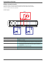
Modbus standard schematic
The standard schematic corresponds to the Modbus specification published in 2002 on www.modbus.org
(Modbus_over_serial_line_V1.pdf, Nov 2002) and, in particular, to the 2-wire multipoint serial bus schematic.
The Lexium Controller conforms to this specification.
Schematic diagram:
Master
T
R
5V
650 Ω
650 Ω
0V
D1
120 Ω
120 Ω
1n F
1n F
D0
Common
R
R
T
T
Slave n
Slave 1
Type of trunk cable
Shielded cable with 1 twisted pair and at least a 3rd conductor
Maximum length of bus
1000 m at 19200 bps with the Telemecanique TSX CSA* cable
Maximum number of stations (without repeater) 32 stations, i.e., 31 slaves
Maximum length of tap links
• 20 m (65.62 ft) for one tap link
• 40 m (131.23 ft) divided by the number of tap links on a multiple junction box
Bus polarization
• One 450 to 650 Ω pull-up resistor to the 5 V (650 Ω or thereabouts recommended)
• One 450 to 650 Ω pull-down resistor to the Common (650 Ω or thereabouts
recommended)
This polarization is recommended for the master.
Line termination
One 120 Ω 0.25 W resistor in series with a 1nF 10 V capacitor
Common polarity
Yes (Common), connected to the protective ground at one or more points on the bus
9
Connection to the bus
Connecting via RJ45 wiring system
1 - Master (PLC, PC or communication module)
2 - Modbus cable depending on the type of master (see table page 11)
3 - Modbus splitter box LU9 GC3
4 - Modbus drop cables VW3 A8 306 R**
5 - Line terminators VW3 A8 306 RC
6 - T-junction boxes VW3 A8 306 TF** (with cable)
7 - Modbus cable (to another splitter box) TSX CSA*00
LMC
Connection accessories
Description
No.
Reference
Modbus splitter
box
10 RJ45 connectors and 1 screw terminal
3
LU9 GC3
Modbus T-junction boxes
With integrated cable (0.3 m)
6
VW3 A8 306 TF03
With integrated cable (1 m)
6
VW3 A8 306 TF10
R = 150 Ω
5
VW3 A8 306 R
Line
terminators
For RJ45 connector
Connection cables
Description
Length (m)
Connectors
Cables for
Modbus bus
3
1 RJ45 connector and 1 stripped end
0.3
2 RJ45 connectors
4
VW3 A8 306 R03
1
2 RJ45 connectors
4
VW3 A8 306 R10
3
2 RJ45 connectors
4
VW3 A8 306 R30
100
Supplied without connector
7
TSX CSA 100
200
Supplied without connector
7
TSX CSA 200
500
Supplied without connector
7
TSX CSA 500
RS 485 double
shielded twisted
pair cables
10
No.
Reference
VW3 A8 306 D30
Connection to the bus
Type of master
Master interface
Modbus connection accessories for RJ45 wiring system
Description
Twido PLC
Adaptor or mini-DIN
3 m cable equipped with a mini-DIN connector and an
RS485 interface module RJ45 connector
Reference
TWD XCA RJ030
Adaptor or screw
terminal RS485
interface module
3 m cable equipped with an RJ45 connector and stripped
at the other end
VW3 A8 306 D30
Mini-DIN RS485
connector port
3 m cable equipped with a mini-DIN connector and an
RJ45 connector
TWD XCA RJ030
PCMCIA card
(TSX SCP114)
Stripped cable
TSX SCP CM 4030
TSX SCY 11601 or TSX
SCY 21601 module
(25-way SUB-D socket)
Cable equipped with a 25-way SUB-D connector and
stripped at the other end (for connection to the screw
terminals of the LU9GC3 splitter box)
TSX SCY CM 6030
PCMCIA card
(TSX SCP114)
Stripped cable
TSX SCP CM 4030
Ethernet bridge
(174 CEV 300 10)
Screw terminal RS485
3 m cable equipped with an RJ45 connector and stripped
at the other end
VW3 A8 306 D30
PROFIBUS DP gateway
(LA9P307)
RJ45 RS485
1 m cable equipped with 2 RJ45 connectors
VW3 P07 306 R10
Fipio (LUFP1) or
PROFIBUS DP (LUFP7) or
DeviceNet (LUFP9)
gateway
RJ45 RS485
0.3 m cable equipped with 2 RJ45 connectors or
1 m cable equipped with 2 RJ45 connectors or
3 m cable equipped with 2 RJ45 connectors
VW3 A8 306 R03 or
VW3 A8 306 R10 or
VW3 A8 306 R30
PC with serial port
PC with male 9-way
SUB-D RS232 serial
port
RS232/RS485 converter and 3 m cable equipped with
an RJ45 connector and stripped at the other end (for
connection to the screw terminals of the LU9GC3 splitter
box)
TSX SCA 72 and
VW3 A8 306 D30
TSX Micro PLC
TSX Premium PLC
11
Connection to the bus
Connecting via junction boxes
1 - Master (PLC, PC or communication module)
2 - Modbus cable depending on the type of master (see table page 13)
1
2
3 - Modbus cable TSX CSA*00
5
3
4
4 - Junction box TSX SCA 50
5 - Subscriber socket TSX SCA 62
6
7
6 - Modbus drop cable VW3 A8 306
7 - Modbus drop cable VW3 A8 306 D30
LMC
Connection accessories
Description
No.
Reference
Junction box
3 screw terminals and an RC line terminator, to be connected using cable VW3 A8 306 D30
4
TSX SCA 50
Subscriber socket
2 female 15-way SUB-D connectors, 2 screw terminals, and an RC line terminator, to be connected
using cable VW3 A8 306 or VW3 A8 306 D30
5
TSX SCA 62
Connectors
No.
Reference
1 RJ45 connector and one stripped end
7
VW3 A8 306 D30
3
1 RJ45 connector and 1 male 15-way SUB-D connector for
TSX SCA 62
6
VW3 A8 306
100
Supplied without connector
3
TSX CSA 100
200
Supplied without connector
3
TSX CSA 200
500
Supplied without connector
3
TSX CSA 500
Connection cables
Description
Length (m)
Cables for Modbus bus 3
RS 485 double shielded
twisted pair cables
12
Connection to the bus
Type of master
Master interface
Modbus connection accessories for junction boxes using screw
terminals
Description
Reference
Twido PLC
Adaptor or screw terminal
RS485 interface module
Modbus cable
TSX CSA100 or
TSX CSA200 or
TSX CSA500
TSX Micro PLC
Mini-DIN RS485
connector port
Junction box
TSX P ACC 01
PCMCIA card (TSX SCP114)
Cable equipped with a special connector and
stripped at the other end
TSX SCP CU 4030
TSX SCY 11601 or
TSX SCY 21601 module
(25-way SUB-D socket)
Cable equipped with a 25-way SUB-D
connector and stripped at the other end
TSX SCY CM 6030
PCMCIA card (TSX SCP114)
Cable equipped with a special connector and
stripped at the other end
TSX SCP CU 4030
Ethernet bridge
(174 CEV 300 10)
Screw terminal RS485
Modbus cable
TSX CSA100 or
TSX CSA200 or
TSX CSA500
PROFIBUS DP gateway
(LA9P307)
RJ45 RS485
3 m cable equipped with an RJ45 connector
and stripped at the other end
VW3 A8 306 D30
Fipio (LUFP1) or
PROFIBUS DP (LUFP7) or
DeviceNet (LUPF9) gateway
RJ45 RS485
3 m cable equipped with an RJ45 connector
and stripped at the other end
VW3 A8 306 D30
PC with serial port
PC with male 9-way SUB-D
RS232 serial port
RS232/RS485 converter and
Modbus cable
TSX SCA 72 and
TSX CSA100 or
TSX CSA200 or
TSX CSA500
Type of master
Master interface
Description
Reference
Twido PLC
Adaptor or screw terminal RS485
interface module
-
-
TSX Micro PLC
Mini-DIN RS485 connector port
-
-
PCMCIA card (TSX SCP114)
Cable equipped with a special connector and
a SUB-D 25 connector
TSX SCY CU 4530
TSX SCY 11601 or
TSX SCY 21601 module
(SUB-D 25 socket)
Cable equipped with a 25-way SUB-D
connector and stripped at the other end
TSX SCP CU 4530
PCMCIA card (TSX SCP114)
Cable equipped with a special connector and
stripped at the other end
TSX SCY CU 4530
Ethernet bridge
(174 CEV 300 10)
Screw terminal RS485
-
-
PROFIBUS DP gateway
(LA9P307)
RJ45 RS485
-
-
Fipio gateway (LUFP1) or
PROFIBUS DP gateway
(LUFP7)
RJ45 RS485
3 m cable equipped with an RJ45 connector
and a SUB-D 25 connector
VW3 A8 306
PC with serial port
PC with male 9-way SUB-D
RS232 serial port
-
-
TSX Premium PLC
TSX Premium PLC
Modbus connection accessories for junction boxes using
SUB-D 15
13
Connection to the bus
Connecting on screw terminals
Connection accessories
Description
Line
terminators
Reference
For screw terminals
R = 150 Ω
VW3 A8 306 DR
Connection cables
Description
Length (m)
Connectors
Reference
Cables for
Modbus bus
3
1 RJ45 connector and one stripped end
VW3 A8 306 D30
RS 485 double shielded
twisted pair cables
100
Supplied without connector
TSX CSA 100
200
Supplied without connector
TSX CSA 200
500
Supplied without connector
TSX CSA 500
14
Configuration
Configuring the Modbus network
The parameters of the Modbus network can be configured via the graphic display terminal or using the Motion Pro/CoDeSys software.
Configuration via the graphic display terminal
The parameters [Modbus address] and [Modbus baudrate] are available in the sub-menu [LC CONFIGURATION].
Modbus parameter
Description/Possible values
Terminal
display
Default
value
[Modbus address]
1 to 247
0 = Lexium Controller Modbus server disabled
[1] to [247]
[0]
[0]
[Modbus baudrate]
Baudrate of Modbus communication
[9600], [19200], [38400]
[38400]
NOTE:
The graphic display terminal will only operate at 38400 bps and the value 8-N-1 (8 bits sent - no parity - 1 stop bit).
Any other value will make communication with the graphic display terminal impossible.
Configuration using the Motion Pro/CoDeSys software
The configuration can be read via the PLC-Browser key word.
The key word for ascertaining the address and speed of the Modbus network is mbusinf.
15
Configuration
The key word for configuration of the Modbus network address is, for example with address 2: mbaddr 2
16
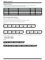
Diagnostics
Modbus LEDs
MODBUS
The Modbus LEDs are located on the RJ45 port, on the front panel of the Lexium Controller. They indicate the Modbus communication
status.
STATUS
LED
Each LED lights up for 200 ms when a frame is being transmitted on the corresponding Modbus network, whether or not this is destined for
the Lexium Controller.
Communication management and communication interruptions
If there is no Modbus communication, the LEDs on the graphic display terminal are off.
There is no specific Modbus communication interruption LED.
• Following initialization (power-up), the Lexium Controller checks that frames are being sent on the Modbus network. These frames can
be sent from a Modbus PLC or an HMI, and also from a PC on which the Motion Pro/CoDeSys software is running.
If the cable is disconnected from the Modbus master, then reconnected in order to communicate using the Motion Pro/CoDeSys software,
the Lexium Controller automatically detects the Motion Pro/CoDeSys frame format with no action required from the user.
It is possible to reconnect to the Modbus Master again with no action required from the user.
• Thus, when a Modbus communication interruption occurs, the Lexium Controller does not react. The communication interruption must
be managed by the Modbus Master, from a PLC, a PC, an industrial terminal (Magelis), or a SCADA monitoring the Lexium Controller.
17
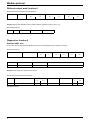
Modbus protocol
RTU mode
RTU transmission mode is used. The frame contains no message header byte and no end of message byte.
It is defined as follows:
Slave
address
Request code
Data
CRC16
The data is transmitted in binary code.
CRC16: Cyclic redundancy check parameter.
The end of the frame is detected on a silence greater than or equal to 3.5 characters.
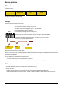
Principle
The Modbus protocol is a master-slave protocol.
Only one device can transmit on the line at any one time.
The master manages the exchanges and only it can take the initiative.
Master
It interrogates each of the slaves in succession.
No slave can send a message unless it is invited to do so.
In the event of an error during data exchange, the master repeats the question and declares
the interrogated slave absent if no response is received within a given time period.
If a slave does not understand a message, it sends an exception response to the master.
The master may or may not repeat the request.
Slave i
Slave j
Slave k
Direct slave to slave communication is not possible.
For slave to slave communication, the master application software must be designed accordingly: to interrogate a slave and send back the
data received to the other slave.
Two types of dialog are possible between master and slaves:
• The master sends a request to a slave and waits for it to respond.
• The master sends a request to all slaves without waiting for them to respond (broadcasting principle).
Addresses
• The Modbus addresses of the Lexium Controller can be configured from 1 to 247.
• Address 0 coded in a request sent by the master is reserved for broadcasting. The Lexium Controller takes account of the request but
does not respond to it.
• The Lexium Controller has a Modbus server that has its own address:
- A Modbus server to enable the Lexium Controller to access all the parameters available in the Modbus table.
- The list of these parameters and variables (%MW…) used by the Motion Pro/CoDeSys software can be found in the document:
18
Modbus protocol
Modbus functions
The following table indicates which Modbus functions are managed by the Lexium Controller and specifies their limits.
The "read" and "write" functions are defined from the point of view of the master.
Code
Modbus name
Function name
Broadcasting
Max. value of N
3 = 16#03
Read Holding Registers
Read N output words
NO
121 words max.
6 = 16#06
Write Single Register
Write one output word
YES
–
8 = 16#08
Diagnostics
Diagnostics
NO
16 = 16#10
Write Multiple Registers
Write N output words
YES
121 words max.
43 = 16#2B
Read Device Identification
Identification
NO
–
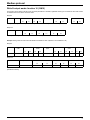
Read N output words: function 3
Note: Hi = most significant bits, Lo = least significant bits.
This function can be used to read the Lexium Controller parameters, regardless of their type.
Maximum size of the number of variables that can be read in one frame: 121
Request
Slave no.
03
1 byte
No. of first word
Number of words
Hi
Hi
1 byte
Lo
2 bytes
CRC16
Lo
Lo
2 bytes
Hi
2 bytes
Response
Slave no.
03
1 byte
Number of
bytes read
1 byte
First word value
Hi
1 byte
-------
Lo
Last word value
Hi
2 bytes
CRC16
Lo
Lo
2 bytes
Hi
2 bytes
Example 1: Using function 3 to read the 4 words %mW3102 (W3102) to %mW3105 (W3105) (16#0C1E to 16#0C21) in slave 2, where:
•
•
•
•
%mw3102 V (W3102 = 16#0028)
%mw3102 V (W3103 = 16#0258)
%mw3104 V (W3104 = 16#01F4)
%mw3105 V (W3105 = 16#0000)
Request
02
03
0C1E
0004
276C
Response
02
03
Value of:
08
0028
0258
01F4
0000
W3 102
W3 103
W3 104
W3 105
52B0
19
Modbus protocol
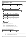
Write one output word: function 6
Request and response (the frame format is identical)
Slave no.
06
Word number
Hi
1 byte
1 byte
Value of word
Lo
Hi
2 bytes
CRC16
Lo
Lo
2 bytes
Hi
2 bytes
Example: Writing value 16#000D to word %mw9001 (W9001) (16#2329) in slave 2 (value = 13).
Request and response:
02
06
2329
000D
9270
Diagnostics: function 8
Subcode 16#00: echo
This function asks the slave being interrogated to echo (return) the message sent by the master in its entirety.
Request and response:
Slave no.
08
Sub-code
Hi
1 byte
1 byte
Data
Lo
Hi
2 bytes
CRC16
Lo
Lo
N bytes
Sub-code
Request data
Response data
00
XX YY
XX YY
Echo
Sub-code
Value of 1st byte
Hi
2 bytes
Function executed
Example: Values 16#31 and 16#32 echoed by slave 4
Request and response (if function successful)
Slave no.
Request code or Response code
04
(hexadecimal values)
20
08
Hi
Lo
00
00
31
Value of 2nd byte
32
CRC16
Lo
Hi
74
1B
Modbus protocol
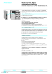
Write N output words: function 16 (16#10)
This function can be used to write the Lexium Controller parameters or variables, regardless of their type. The maximum size of the number
of variables that can be read in one frame is 121.
Request
Slave no.
10
No. of first word
Hi
1 byte
1 byte
Number of words
Lo
Hi
2 bytes
Number of bytes
Value of first word
Lo
Hi
2 bytes
1 byte
-------
CRC16
Lo
Lo
2 bytes
Hi
2 bytes
Response
Slave no.
10
No. of first word
Hi
1 byte
1 byte
Number of words
Lo
Hi
2 bytes
Lo
2 bytes
CRC16
Lo
Hi
2 bytes
Example: Writing values 20 and 30 to words W9001 and W9002 in slave 2 (W9001 to 20 and W9002 to 30)
Request
Slave no.
02
Request
code
10
No. of first word
Number of
words
Hi
Lo
Hi
Lo
23
29
00
02
Number of
bytes
04
Value of first word
Value of second
word
CRC16
Hi
Lo
Hi
Lo
Lo
Hi
00
14
00
1E
73
A4
Response
Slave no.
02
Response code
10
No. of first word
Number of words
CRC16
Hi
Lo
Hi
Lo
Lo
Hi
23
29
00
02
9B
B7
(hexadecimal values)
21
Modbus protocol
Identification: function 43 (16#2B)
Request
Slave no.
2B
Type of MEI
0E
ReadDeviceId
01
Object Id
00
CRC16
1 byte
1 byte
1 byte
1 byte
1 byte
Slave no.
2B
Type of MEI
0E
ReadDeviceId
01
Degree of conformity
02
1 byte
1 byte
1 byte
1 byte
1 byte
Lo
Hi
2 bytes
Response
-------
-------
-------
-------
Number of additional frames
00
Next object Id
00
Number of objects
04
1 byte
1 byte
1 byte
Id of object no. 1
00
Length of object no. 1
0D
Value of object no. 1
“Telemecanique”
1 byte
1 byte
13 bytes
Id of object no. 2
01
Length of object no. 2
0B
Value of object no. 2
“LMC20”
1 byte
1 byte
11 bytes
Id of object no. 3
02
Length of object no. 3
04
Value of object no. 3
“0201”
1 byte
1 byte
04 bytes
-------
-------
-------
-------
-------
-------
CRC16
Lo
Hi
1 byte
1 byte
The total response size given in this example equals 55 bytes
The response contains the following three objects:
• Object no.
1:
Manufacturer name (always "Telemecanique", i.e., 13 bytes).
• Object no.
2:
Device reference (ASCII string; for example: “LMC20”, i.e.,11 bytes).
The length of this object varies according to device type. Use the “Length of object no. 2” field to determine the length.
• Object no.
3:
Device version, in "MMmm" format where "MM" represents the determinant and "mm" the subdeterminant
(4-byte ASCII string; for example: “0201” for version 2.1).
Negative response specifically related to the Identification function:
Slave no.
2B + 80
AB
Type of MEI
0E
Error code
00 to 02
1 byte
1 byte
1 byte
1 byte
Error code:
16#00 =
16#01 =
16#02 =
22
CRC16
Lo
Hi
1 byte
1 byte
No error
The question code (16#2B), the Type of MEI (16#0E) or the ReadDeviceId (16#01) contained in the question
is incorrect.
The Object Id (16#00) contained in the question is incorrect.
Modbus protocol
Exception responses
An exception response is returned by a slave when it is unable to perform the request addressed to it.
Format of an exception response:
Slave no.
Response code
CRC16
Error code
Lo
1 byte
1 byte
1 byte
Hi
2 bytes
Response code: function code of the request + 16#80 (the most significant bit is set to 1).
Error code:
1 = The requested function is not recognized by the slave
2 = The word addresses indicated in the request do not exist in the slave
3 = The word values indicated in the request are not permissible in the slave
4 = The slave has started to execute the request but cannot continue to process it completely
Read non-existent or protected parameters
When a set of parameters is read or when a non-existent or protected parameter is written by a Modbus function, the Lexium Controller
sends an exception response.
The list of parameters or variables that can be accessed by Modbus is as follows:
• From 0 to 59999, all the parameters are available.
• A large number of the parameters from 60000 upwards are not available and are used for Ethernet connectivity and functions.
• After the Ethernet parameters, the zone does not exist.
For a list of the available Ethernet parameters, refer to the Ethernet manual.
23
30072 - 452 - 88
09.2008