1
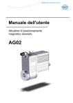
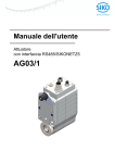
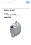
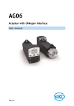
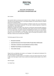
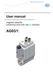
User manual magnetic absolute positioning drive AG03/1 1 1.1 1.2 GENERAL REMARKS..................................................................................................................... 3 DOCUMENTATION ........................................................................................................................ 3 BLOCK DIAGRAM ......................................................................................................................... 3 2 FUNCTIONAL DESCRIPTION ........................................................................................................ 4 2.1 2.2 2.3 2.4 2.5 2.6 SYSTEM STATUS WORD ................................................................................................................ 4 OPERATING MODES ..................................................................................................................... 5 2.2.1 Positioning mode ............................................................................................................... 5 2.2.1.1 Loop positioning ......................................................................................................... 6 2.2.1.2 Inching operation ........................................................................................................ 7 2.2.2 Velocity mode .................................................................................................................... 9 TORQUE DEACTIVATION ............................................................................................................. 10 RESTORE FACTORY SETTINGS VIA DIP SWITCHES ....................................................................... 10 SUPPLY VOLTAGE OF CONTROL ND OUTPUT STAGE ...................................................................... 11 DRIVE BEHAVIOR IN CASE OF POWER FAILURE ............................................................................. 11 3 CALIBRATION ............................................................................................................................... 11 4 EXTERNAL GEAR UNIT ............................................................................................................... 11 5 WARNINGS / FAULTS .................................................................................................................. 12 5.1 5.2 W ARNINGS ................................................................................................................................ 12 FAULTS ..................................................................................................................................... 12 5.2.1 Error codes ...................................................................................................................... 13 6 PARAMETER DESCRIPTION ....................................................................................................... 13 7 COMMUNICATION VIA PROFIBUS – DP .................................................................................... 17 7.1 7.2 7.3 7.4 GENERAL REMARKS ................................................................................................................... 17 INTERFACE ................................................................................................................................ 17 DATA EXCHANGE ....................................................................................................................... 17 TELEGRAM SETUP (DATA EXCHANGE) ........................................................................................ 18 7.4.1 Parameter Process Data Object ...................................................................................... 18 7.4.2 Parameter identification value (PKW) .............................................................................. 18 7.4.2.1 Parameter identification (PKE) ................................................................................. 18 7.4.2.2 Sub-index (IND) ........................................................................................................ 20 7.4.2.3 Parameter value (PWE)............................................................................................ 20 7.4.3 Process data (PZD) ......................................................................................................... 20 7.5 FUNCTIONAL DESCRIPTION OF THE CONTROL UNITS ..................................................................... 21 7.5.1 Control word in positioning mode (master slave) ........................................................ 22 7.5.2 Status word: Positioning mode (slave master) ............................................................ 23 7.5.3 Flow chart: Operating mode: Positioning mode ............................................................... 24 7.5.4 Control word: Velocity mode (master slave) ............................................................... 25 7.5.5 Status word: Velocity mode (slave master) ................................................................. 26 7.5.6 Flow chart: Operating mode: Velocity mode .................................................................... 27 7.6 PARAMETERIZATION VIA PROFIBUS ............................................................................................. 28 7.6.1 Example: read parameter ................................................................................................ 31 7.6.2 Example: Write parameter ............................................................................................... 32 7.7 DIAGNOSIS ................................................................................................................................ 33 7.8 PROFIBUS ADDRESS SETUP ........................................................................................................ 34 7.9 DIAGNOSIS LEDS ...................................................................................................................... 35 7.10 PROFIBUS BUS TERMINATOR ...................................................................................................... 35 7.11 DEVICE DATA BASE AND CONFIGURATION .................................................................................... 35 AG03/1 (PB) Date: 08.07.2015 Page 2 of 35 Art.No. 86674 Mod. status 251/15 1 General remarks This user manual is valid with firmware version 1.00 or higher! 1.1 Documentation The following documents are associated with this document: • The data sheet describes the technical data, the dimensions, the pin assignment, the accessories and the order key. • The installation instructions describe the mechanical and electrical installation with all safetyrelevant conditions and the associated technical specifications. • The User manual for actuator commissioning and integration into a fieldbus system. You can also download these documents at http://www.siko-global.com/en-de/servicedownloads. 1.2 Block Diagram Profibus galvanic separation +UB control +UB output stage Inversepolarity protection Mains adapter Inversepolarity protection Control Output stage Motor Gear Encoder Battery AG03/1 (PB) Date: 08.07.2015 Page 3 of 35 Art.No. 86674 Mod. status 251/15 2 Functional description This chapter describes the operating cycles, functions and states required for the operation of the positioning drive. Communication via Profibus DP is taken as the basis for the information presented in this chapter. 2.1 System status word The system status word of the AG03/1 consists of 2 bytes and reflects the state of the AG03/1. The System status word can be read out as a hexadecimal value via Profibus Parameter 1020dec (see chapter 7.6: Parameterization via Profibus). High- Byte 15 0 14 0 13 1 12 0 11 1 Low- Byte 10 0 Bit – number 9 8 7 6 0 1 0 1 2 9 Fig. 1: System status word format 5 0 4 4 0 3 1 2 0 1 0 0 0 8 Example (grey background): binary: 0010 1001 0100 1000 hex: 2 9 4 8 The table below informs about the meaning of the individual bits of the status word: Bit Bit 0 Bit 1 Bit 2 Bit 3 State ‘0‘ ‘0‘ ‘0‘ ‘1‘ ‘0‘ ‘1‘ ‘0‘ Bit 4 ‘1‘ ‘0‘ Bit 5 ‘1‘ ‘0‘ ‘0‘ Bit 6 ‘1‘ ‘0‘ ‘0‘ AG03/1 (PB) Description no meaning no meaning no meaning Positioning mode: In position Actual position is within the positioning window of the programmed target value. Actual position is beyond the positioning window of the programmed target value. Velocity mode: In position Actual velocity is within the specified tolerance window of the target speed Actual speed is outside the specified tolerance window. Drive travels: Drive travels Drive stands still (velocity <2 rev./min) Positioning mode: upper limit: Actual position is above the higher programmed limit of limits 1+2. Travelling is possible only in negative direction in inching operation. Actual position is below the programmed limit. Velocity mode: no meaning Positioning mode: lower limit: Actual position is below the lower programmed limit of limits 1+2. Travelling is possible only in positive direction in inching operation. Actual position is above the programmed limit. Velocity mode: no meaning Date: 08.07.2015 Page 4 of 35 Art.No. 86674 Mod. status 251/15 Bit Bit 7 Description Driver state: ‘1‘ Motor is enabled ‘0‘ Motor in control Fault: Bit 8 ‘1‘ The AG03/1 has switched to fault. The cause of the fault must be cleared and acknowledged via ‘STW.7=1’ command. For the fault cause see chapter 5.2 ‘0‘ No fault present Positioning mode: loop travel: Bit 9 ‘1‘ If travel direction unequal start direction (with loop travel) ‘0‘ If travel direction equal start direction Velocity mode: no meaning ‘0‘ Supply voltage of output stage Bit 10 ‘1‘ Supply voltage of output stage not applied: Gear travel is disabled! ‘0‘ Supply voltage of output stage applied Ready-to-travel: Bit 11 ‘1‘ Not ready-to-travel ‘0‘ Ready-to-travel: AG03/1 not in fault state No active positioning Supply voltage of output stage applied actual position within limits (only positioning mode) Battery voltage: Bit 12 ‘1‘ Battery voltage too low for absolute encoder. Replace the battery within half a year after reporting of the error bit! ‘0‘ Battery voltage OK. Motor current: Bit 13 ‘1‘ Motor current beyond permissible range. If this state lasts for more than 4 s, the AG03/1 switches to fault. ‘0‘ Motor current within permissible range. Positioning mode: status Bit 14 ‘1‘ Positioning active in positioning mode. ‘0‘ Positioning inactive. Velocity mode: no meaning ‘0‘ Lag error: Bit 15 ‘1‘ Lag error AG03/1 cannot reach the preset speed due to too high load. This state should be avoided! Remedy: reduce programmed speed! ‘0‘ No lag error actual speed corresponds with required speed. Table 1: System status word 2.2 State Operating modes The following operating modes are available: positioning mode and velocity mode. In the positioning mode there is the additional option of travelling with inching operation. 2.2.1 Positioning mode Parameter no 20 ‘Operating mode’ is programmed to positioning mode (see chapter 6: Parameter description). In the positioning mode, positioning to the target value is effected by means of a ramp function (see fig. 2), which is calculated on the basis of the actual position as well as the programmed controller parameters P (proportional factor), I (integral factor), D (differential factor), acceleration and speed (see chapter 6: Parameter description). AG03/1 (PB) Date: 08.07.2015 Page 5 of 35 Art.No. 86674 Mod. status 251/15 After activation of the travel order (see chapter 7.5.3 Flowchart: Positioning mode) the AG03/1 accelerates with the pre-programmed acceleration to the specified speed. The measure of deceleration to reach the target value is also defined by the parameter ‘a-pos’. As an alternative you can also choose a value for delay that deviates from acceleration (see chapter 6: Parameter No. 31 ‘d-Pos‘). If the actual position is within the programmed window (see chapter 6: parameter no. 10), this will be signalled in the system status word (bit 3). The drive’s behaviour upon reaching the pre-programmed window can be defined (see chapter 6: parameter no. 26). Changing controller parameters during a positioning process does not influence the current positioning operation. Speed Speed (Parameter No. 5) Delay (Parameter No. 4) Acceleration (Parameter No. 4) Delay (Parameter No. 31) Start position Target position Time Fig. 2: Ramp travel in positioning mode (direct) Travel orders can only be started if the following conditions have been met: the AG03/1 must not be switched to fault (system status word bit 8 = ‘0’) actual position is within the programmed limiting values. (system status word bits 5 + 6 = ‘0’) no active travel job present (system status word bit 14 = 0) Supply voltage of the output stage is applied (system status word bit 10 = ‘0‘) ZSW.15 = ‘1‘ is signalled when these conditions have been met. 2.2.1.1 Loop positioning If the AG03/1 is operated on a spindle or an additional drive, the spindle or external drive play can be compensated by means of loop positioning. In this case, travelling to the target value is always from the same direction. This travel direction can be defined via the parameter no. 19 ‘Pos- Art’ (see chapter 6: Parameter description). Example: Assumption: The direction of travelling for reaching any target position is positive (see chapter 6: Parameter no. 19 ‘Pos Art’ = loop) AG03/1 (PB) Date: 08.07.2015 Page 6 of 35 Art.No. 86674 Mod. status 251/15 Case 1 new position is greater than actual position: Direct travel to target position. Case 2 new position is smaller than actual position: The AG03/1 travels beyond the target position by the loop length (parameter no. 27) (bit 9 in the system status word signals travel direction unequal start direction); afterwards, travelling to the target value is in positive direction. Positioning: Loop + Loop length (Parameter no. 27) Positioning in positive direction - Positioning in negative direction Target value + Fig. 3: Loop+ positioning 2.2.1.2 Inching operation Inching operation is enabled in the ‘Positioning mode’ only. Acceleration and speed in the inching operation can be programmed via parameter no. 8 ‘a- Inch’ and parameter no. 9 ‘vInch’. NOTICE There is no compensation for spindle play (loop positioning) in this travel type! There are three options for travelling with inching operation: Inching operation 1 Inching operation 1 is started via STW.8 = ‘1‘ in the control word. The drive travels once from the current position by the position ‘Delta Inch’. The travel direction is positive or negative depending on the arithmetical sign (parameter no. 17 ‘Delta- Inch’). - Parameter ‘Delta Inch’ < 0: negative travel direction Parameter ‘Delta Inch’ > 0: positive travel direction If the parameter no. 13 ‘Spindle pitch’ is programmed to zero, then there is an incremental travelling way. If the ‘spindle pitch’ is unequal zero, then the information of the ‘Delta Inch’ parameter refers to the travel distance in 1/100 mm. Reaching the target position will be signalled in the system status word (bit 3). AG03/1 (PB) Date: 08.07.2015 Page 7 of 35 Art.No. 86674 Mod. status 251/15 Inching operation 2 Inching operation 2 is started via STW.9 = ‘1‘. The drive moves as long as this bit = ‘1‘ . The drive direction depends on STW.15: STW.15 = ‘0‘ positive travel direction STW.15 = ‘1‘ negative travel direction The inching speed can be influenced via two parameters and will be calculated in the drive as shown in the following example: v - Inch (parameter no 9) = 50 rpm (changeable only during standstill) Offset Inching 2 (parameter no. 30) = 47 % (changeable during inching operation) In this example, the resulting incing speed is: Inching speed = v - inch * offset inching 2 = rpm * 47 % = 24 rpm Results are always rounded up to integers. The minimum speed is 1 rpm. Manual setup mode 2 1 The manual setup mode (corresponding to inching operation 2) can be started by means of the operator keys enabling traveling of the actuator without a superordinate control. Key (1) clockwise movement Key (2) counter-clockwise movement NOTICE AG03/1 (PB) The manual setup mode is only available if the Profibus finite state machine of AG03/1 is not in the Data Exchange status! Date: 08.07.2015 Page 8 of 35 Art.No. 86674 Mod. status 251/15 The following conditions must be met to enable the start of inching operation 1 and 2 or manual setup operation, repectively: The AG03/1 must not be switched to fault (system status word bit 8 = ‘0’) No active travel job present (system status word bit 14 = ‘0’) Supply voltage of the output stage is applied (system status word bit 10 = ‘0‘) NOTICE 2.2.2 If the actual position is outside the programmed limits, traveling in the relevant direction is possible by means of inching operation 1 or 2 or manual setup! Velocity mode Parameter no 20 ‘operating mode’ is programmed to velocity mode (see chapter 6: Parameter description). In the velocity mode, the AG03/1 accelerates to the target velocity after release of the setpoint value (see chapter 7.5.6 Flow chart: velocity mode) and maintains this velocity until the setpoint value is disabled or a new target velocity specified. The speed is adjusted immediately to the new value when the rotational target speed is changed. The arithmetical sign of the target value determines the travel direction in the velocity mode (see chapter 6: Parameter description). Velocity Target speed (Sollwert) Disable operation Disable setpoint or setpoint = 0 Acceleration (’a - Rot’ parameter ) Time 'Stop' Target value released Fig. 5: Ramp velocity mode The following conditions must be met for enabling start of velocity mode via the ‘M’ command of the standard protocol: The AG03/1 must not be switched to fault (system status word bit 8 = ‘0’) no active travel job present (system status word bit 14 = ‘0’) Supply voltage of the output stage is applied (system status word bit 10 = ‘0‘) If these conditions are met, this will be signalled in the system status word by bit 11 = ‘0’. NOTICE AG03/1 (PB) Limits 1 + 2 are deactivated in this operational mode! Date: 08.07.2015 Page 9 of 35 Art.No. 86674 Mod. status 251/15 2.3 Torque deactivation A deactivation threshold is defined via the torque deactivation parameter (see chapter 6: Parameter description Parameter No. 29). Percent values are entered. Torque deactivation is disabled with a parameter value of 125 %. The drive will decelerate with maximum delay when the deactivation threshold is exceeded. Drive control will be maintained. NOTICE Active torque deactivation causes no error! Active torque deactivation is returned via bit 7 = ‚1’ in parameter 1031dec (general status register). This bit will be automatically reset when the current travel order is resumed. NOTICE 2.4 This function is only available in the positioning mode! Restore factory settings via DIP switches Procedure for restoring factory settings via the 10-pin DIP switch: 1. Switch off supply voltage. 2. Set DIP switches 1 – 8 depending on the parameters to be reset: Reset all parameters (see chapter 6: Parameter description) to factory settings Reset only standard parameters (see chapter 6: Parameter description) to factory settings Reset only controller parameters (see chapter 6: Parameter description) to factory settings 3. Turn on supply voltage. AG03/1 acknowledges with alternating blinking of the status LED and the bus LED. 4. Switch off supply voltage. AG03/1 (PB) Date: 08.07.2015 Page 10 of 35 Art.No. 86674 Mod. status 251/15 5. Set the original bus address via DIP switches 1 - 7. 6. DIP switch number 8 must be set to the OFF position. 7. After next switching on of supply voltage, the previously selected parameters will have been reset to the factory settings. 2.5 Supply voltage of control nd output stage Both supply voltages must be applied to enable the start of traveling jobs. 2.6 Drive behavior in case of power failure NOTICE 3 Power failure results in immediate loss torque. If the drive is moving at the time of power failure, then the drive will run out non-braked! Calibration Since the measuring system is an absolute system, calibration is necessary only once at startup. During calibration, the position value of the AG03/1 is set to the programmed calibration value (see chapter 6: Parameter description parameter no. 14). The measuring system is calibrated via Profibus (see chapter 7.6: Parameterization via Profibus parameter no. 970). NOTICE 4 Calibration is only possible when no travel job is active! External gear unit If an external gear unit is used, a factor can be programmed via the parameter no. 11 ‘ü Numerator’ (numerator) and parameter no. 12 ‘ü – Denominator’ (denominator), in order to include the gear ratio in position sensing (see also chapter 2.2.1.1). Example (see fig. 7): The AG03/1 is operated on a gear with transfer reduction of 5:1. For this purpose, the parameters ‘ü-Numerator’ and ‘ü-Denominator’ must be programmed as follows: AG03/1 (PB) Parameter ‘ü - Numerator‘: Parameter ‘ü - Denominator‘: Date: 08.07.2015 5 1 Page 11 of 35 Art.No. 86674 Mod. status 251/15 5 revolution external gear unit 5:1 1 revolution M Gear output AG03/1 with internal drive Fig. 7: External gear unit Input of an odd gear reduction value is possible according to the following example: Transfer reduction = 3.78 5 Parameter ‘ü - Numerator‘: Parameter ‘ü - Denominator‘: 378 100 Warnings / Faults The AG03/1 distinguishes between warnings and faults: 5.1 Warnings Warnings do not influence the operation of the positioning drive. Warnings disappear after removing their causes. Possible warnings: 5.2 Battery voltage for absolute encoder is below limit exchange battery within the next 6 months (see chapter 2.1: system status word bit 12). Motor current beyond the permissible range (see chapter 2.1: System status word bit 13). if this condition lasts longer than 4 s, the AG03/1 will switch to fault. Lag error present (see chapter 2.1: System status word bit 15) AG03/1 cannot reach programmed speed because load is too high. Faults Faults induce an immediate stop of the positioning drive. The status-LED signalizes the fault status (see installation instructions). Based on the blink code, the cause of the fault can be tracked down (see table 2: Error codes). Furthermore, an existing fault can be recogniozed via ZSW.3 = ‘1‘. Faults must be acknowledged after clearing the faults (STW.7 = ‘1‘). The error messages are entered in the error buffer in the order of their detection. The last 10 fault messages are displayed when the fault buffer is full. The cause of an error can be tracked down with the help of the error codes (see table 2: Error codes). The error buffer is stored in the EEPROM and can be deleted via Profibus Parameter 970 dec. AG03/1 (PB) Date: 08.07.2015 Page 12 of 35 Art.No. 86674 Mod. status 251/15 5.2.1 Error codes The following table lists possible error causes: Value error buffer ASCII HEX A 41h Blink code green Error description Status-LED blinking 1 time B 42h blinking 2 times C 43h blinking 3 times D 44h blinking 4 times E F G 45h 46h 47h blinking 5 times blinking 6 times blinking 7 times J 4Ah blinking 10 times supply voltage too low Error condition: Supply voltage <18 V + motor current >200 mA blocked drive shaft Error condition: Revolutions per minute < rpm + contouring error motor current too high Error condition: Motor current >2.4 A more than 4 s output stage temperature too high Error condition: Output stage temperature >90 °C SIN COS monitoring internal error intermediate circuit voltage too high Error condition: Intermediate circuit voltage >35 V Battery voltage <2.2 V Battery must be replaced Table 2: Error codes 6 Parameter description This chapter describes the parameters of the AG03/1. All parameters are stored in the non-volatile EEPROM, except for parameter no. 24 (target value) and parameter no. 30 (Offset inching 2). * Controller parameters ** Standard parameters Selection / value 1 – 500 Nr. Name 1 Controller parameter P* 2 Controller parameter I* 0 – 500 5 3 Controller parameter D* 0 – 500 0 4 a – Pos * 1 – 100 50 AG03/1 (PB) Date: 08.07.2015 Default 100 Description P gain of controller: valid for all operating modes (positioning mode, velocity mode, inching operation) Profibus chapter 7.6: parameter no. 1000 dec I gain of controller: valid for all operating modes (positioning mode, velocity mode, inching operation) Profibus chapter 7.6: parameter no. 1001 dec D gain of controller: valid for all operating modes (positioning mode, velocity mode, inching operation) Profibus chapter 7.6: parameter no. 1002 dec Acceleration in positioning mode: values in % (100 % 4 U/s²) Profibus chapter 7.6: parameter no. 1003 dec Page 13 of 35 Art.No. 86674 Mod. status 251/15 Selection / value 1 – 100 1 – 200 Nr. Name 5 v – Pos * 6 a - Rot * 1 – 100 50 7 8 a - Inch * 1 – 100 50 9 v - Inch * 1 – 100 1 – 200 30 10 Pos- Window ** 0 - 1000 10 11 ü – Numerator** 1 – 10000 1 12 ü– Denominator** 1 – 10000 1 13 Spindle pitch ** 0 – 1000 0 14 Calibration value ** -999999 to 999999 0 AG03/1 (PB) Date: 08.07.2015 Default Description 30 Maximum speed in positioning mode: values in revolutions/min gear ratio 48:1 max. 100 rev/min gear ratio 24:1 max. 200 rev/min Profibuschapter 7.6: parameter no. 1004 dec Acceleration in velocity mode: values in % (100 % 4 U/s²) Profibus chapter 7.6: parameter no. 1005 dec reserved Acceleration in inching operation 1 /2: values in % (100 % 4 U/s²) Profibus chapter 7.6: parameter no. 1007 dec Maximum speed in inching operation 1 /2: values in revolutions/min gear ratio 48:1 max. 100 rev/min gear ratio 24:1 max. 200 rev/min Profibus chapter 7.6: parameter no. 1008 dec Positioning mode: positioning window If the actual position of the AG03/1 is within the programmed target value ± this window, this is signalled by setting bit 3 in the system status word of the AG03/1 (see chapter 2.1). Spindle pitch = 0: Information refers to increments Spindle pitch ╪ 0: Information refers to travelling distance in 1/100 mm Velocity mode: Velocity window If the actual velocity is within the target velocity ± this window, this is signalled by setting bit 3 in the system status word of the AG03/1 (see chapter 2.1). Profibus chapter 7.6: parameter no. 1009 dec Numerator gear ratio: a gear ratio can be programmed here when a gear unit is used (see chapter 4: external gear unit). Profibus chapter 7.6: parameter no. 1010 dec Denominator gear ratio: a gear ratio can be programmed here when a gear unit is used (see chapter 4: external gear unit). Profibus chapter 7.6: parameter no. 1011 dec Spindle pitch: Spindle pitch = 0: Position value is output in increments (1600 increments per revolution of the driving shaft of the AG03/1). Spindle pitch parameter ╪ 0: (when operating the AG03/1 on a spindle) Position value is no longer output as increments, but as travelling distance in 1/100 mm. Target position is entered now as 1/100 mm, too. Spindle pitch value in 1/100 mm. e. g. spindle with a pitch of 2 mm spindle pitch parameter = 200. Profibus chapter 7.6: parameter no. 1012 dec Calibration value: Writing a value in this parameter results in the take-over of this value as the absolute position for the AG03/1. Caution! Value must be within the range of the preprogrammed limiting values. Profibus chapter 7.6: parameter no. 1018 dec Page 14 of 35 Art.No. 86674 Mod. status 251/15 Nr. Name 15 Limit 1 ** 16 Limit 2 ** 17 Delta Inch ** 18 Sense of rotation ** 19 Pos Type ** 20 Operating mode ** 21 22 23 AG03/1 (PB) Selection / value -9999999 to 9999999 Default Description 1000000 Positioning mode: limit 1 Spindle pitch = 0: Information refers to increments Spindle pitch = ╪0: Information refers to travelling distance in 1/100 mm If the AG03/1 is beyond the range defined by limit 1 and limit 2 (travel range), travelling will only be possible in the direction of the travel range in inching mode. Caution! Limit monitoring is deactivated if ‘limit 1’ is equal ‘limit 2’. Please note that there is a jump of the actual position if the resolution of the absolute encoder is exceeded! Velocity mode: no meaning Profibus chapter 7.6: parameter no. 1016 dec -9999999 -1000000 Positioning mode: limit 2 to Spindle pitch = 0: Information refers to increments 9999999 Spindle pitch = ╪0: Information refers to travelling distance in 1/100 mm If the AG03/1 is beyond the range defined by limit 1 and limit 2 (travel range), travelling will only be possible in the direction of the travel range in inching mode. Caution! Limit monitoring is deactivated if ‘limit 1’ is equal ‘limit 2’. Please note that there is a jump of the actual position if the resolution of the absolute encoder is exceeded! Velocity mode: no meaning Profibus chapter 7.6: parameter no. 1017 dec Delta travelling distance with inching operation 1: -1000000 1600 to indicates the relative travelling distance. 1000000 positive value positive travelling direction negative value negative travelling direction Spindle pitch = 0: Information refers to increments Spindle pitch = ╪0: Information refers to travelling distance in 1/100 mm Profibus chapter 7.6: parameter no. 1019 dec Counting direction of the measuring system: i,e i When the shaft rotates counter-clockwise (view on the clamping ring of the AG03/1). i sense of rotation: positive counting direction e sense of rotation: negative counting direction Profibus chapter 7.6: parameter no. 1013 dec Positioning mode: Type of positioning direct direct direct: direct travelling from actual position to target value loop + loop +: travelling to the target value occurs always in sloop positive direction to compensate for spindle play loop -: travelling to the target value occurs always in negative direction to compensate for spindle play. Caution! Loop positioning in positioning mode only. Velocity mode: no meaning Profibus chapter 7.6: parameter no. 1014 dec positioning positioning Positioning mode: (see chapter 2.2.1: Positioning mode) mode mode Velocity mode: / (see chapter 2.2.2: Velocity mode) speed Profibus chapter 7.6: parameter no. 930 dec mode reserved reserved reserved Date: 08.07.2015 Page 15 of 35 Art.No. 86674 Mod. status 251/15 Selection Default / value see 0 column ‘Description’ Nr. Name 24 Setpoint ** 25 Stop mode Inching mode 2 ** 0/1 0 26 Inpos mode ** 0/1/2 0 27 Loop length** 0 - 10000 800 Torque deactivation ** 20 - 125 125 30 Offset inching 2 ** 10 - 100 100 31 d – Pos * 1 – 101 101 28 29 Description Positioning mode: indicates absolute target position. Spindle pitch = 0: Information refers to increments Spindle pitch = ╪0: Information refers to travelling distance in 1/100 mm Value range: depends on the pre-programmed target values (parameters 15/16) Velocity mode: indicates the target velocity in rev./min. Value range: gear ratio 48:1 max. 100 rev/min gear ratio 24:1 max. 200 rev/min Profibus chapter 7.4: Telegram setup (Data Exchange) Attention! Target value will not be stored in the EEPROM Stop mode inching mode 2 / touch button mode The stop behaviour of inching mode 2 or touch button operation can be parameterized in different ways. Stop mode = 0 stop with maximum delay Stop mode = 1 stop with pre-programmed delay (parameter no. 8) Profibus chapter 7.6: parameter no. 1021 dec Operating mode: positioning mode: The drive’s behaviour upon reaching the positioning window can be determined by this parameter: Inpos mode = 0 position control to setpoint value Inpos mode = 1 position control OFF and short circuit of motor windings Inpos mode = 2 position control OFF and release of drive Velocity mode: no meaning Profibus chapter 7.6: parameter no. 1022 dec Operating mode: positioning mode: Indicates the loop length in increments Velocity mode: no meaning Profibus chapter 7.6: parameter no. 1023 dec reserved Operating mode: positioning mode: This parameter determines the threshold of torque deactivation. Percent values are to be entered. Value 125: Torque deactivation disabled. Velocity mode: no meaning Profibus chapter 7.6: parameter no. 1032 dec Inching operation 2 Witth this parameter, inching speed in inching operation 2 can be influenced. Indication is percentage of parameter no. 9. Caution! This parameter is no stored in the EEPROM. Profibus chapter 7.6: parameter no. 1035 dec Delay in positioning operation: values in % (100 % 4 U/s²) Profibus chapter 7.6: parameter no. 1039 dec Table 6: Parameter description AG03/1 (PB) Date: 08.07.2015 Page 16 of 35 Art.No. 86674 Mod. status 251/15 7 Communication via Profibus – DP 7.1 General remarks This chapter describes the activation and parameterization of the AG03/1 via Profibus interface. For the pin assignment of the Profibus interface please refer to the installation instructions. 7.2 Interface Profibus – DP is an international standardized, open fieldbus standard and is defined in the standards: European Fieldbus Standard EN50170 DIN 19245 parts 1 and 3 The fieldbus is used for cyclic data exchange between a master and the subordinate slaves. Masters determine data traffic on the bus and are called ‘active stations’. Slaves can only acknowledge received messages or transfer messages to the master upon inquiry. Slaves are called ‘passive stations’. The AG03/1 is operated on the Profibus-DP as a slave (passive bus station) and can, therefore, acknowledge messages or send data only upon inquiry from the master. The AG03/1 automatically recognizes the baud rate of the Profibus-DP. The master uniformly sets the baud rate for all devices connected to the Profibus. The AG03/1 supports the following baud rates: 9.6 kBd, 19.2 kBd, 93.75 kBd, 187.5 kBd, 500 kBd, 1.5 MBd, 3 MBd, 6 MBd, 12 MBd Line length: Baud rate in kbit/s 9.6 Line length in m 1200 Table 7: Line length 19.2 1200 93.75 1200 187.5 1000 500 400 1500 200 3000 100 6000 100 12000 100 Termination of the Profibus-DP line: If the AG03/1 is at the end of the bus, the Profibus connection must be terminated using a defined bus terminator. In the AG03/1 this is accomplished via an internal resistor combination that can be connected via DIP switches SW9 + SW10 (see chapter 7.10: Profibus bus terminator). 7.3 Data exchange The flow charts, control functions and status messages as well as the type of cyclic data traffic between master and AG03/1 (slave) are based on the processes and data structures defined in the document Profibus profile for adjustable speed drives, PROFIDRIVE version 2 (September 1997 issue, PNO order no. 3.071). AG03/1 (PB) Date: 08.07.2015 Page 17 of 35 Art.No. 86674 Mod. status 251/15 7.4 Telegram setup (Data Exchange) During operation (Data exchange orange Profibus-LED is lighting, see installation instructions), 7 data words are cyclically exchanged between a master and the AG03/1. The structure of these data words for cyclic data traffic is called “Parameter Process data Object” (PPO) in the Profibus profile “Adjustable-speed Drives” PROFIDRIVE version 2. 7.4.1 Parameter Process Data Object Such a Parameter Process data Object (PPO) consists of two parts: Parameter data range (see chapter 7.4.2: Parameter identification value) Any parameter in the AG03/1 can be monitored or changed by means of the PKW telegram portion (parameter identification value). Process data range (see chapter 7.4.3: Process data) Control words and target values (master slave) or status words and actual values (slave master), respectively, can be transferred with the process data. Definition of the Parameter Process data Object A special PPO type with fixed data length (7 data words) has been defined for the AG03/1: PKW (4 words) PKE IND MSW word 1 word 2 Fig. 8: PPO setup PKW: PKE: IND: PWE: PZD1...3: STW: ZSW: HSW: HIW: LSW: MSW: 7.4.2 PZD1 STW ZSW PWE word 3 word 4 word 5 PZD (3 words) PZD2 PZD3 HSW HSW (master slave) HIW HIW (slave master) LSW word 6 word 7 Parameter identification value Parameter identification Index Parameter value Process data 1 ...3 Control word Status word: Main target value Main actual value lowest-value data word highest-value data word Parameter identification value (PKW) Parameter processing in cyclic data traffic is executed via the PKW portion of the PPO. Here the master formulates a job and sends it to the slave. The master repeats the job until the slave has processed the job and given its reply. The slave makes available the reply until the master formulates a new job. Only one job can be processed at the same time. 7.4.2.1 Parameter identification (PKE) The parameter identification PKE consists of a data word, in which the type of the job/reply and the associated parameter number has been coded. AG03/1 (PB) Date: 08.07.2015 Page 18 of 35 Art.No. 86674 Mod. status 251/15 The parameter identification is made up as follows: PKE (Parameter identification) 14 13 12 11 10 9 8 7 6 5 4 3 2 AK SPM Parameter number (PNU) Fig. 9: PKE setup 15 1 0 AK: Job or reply identification, respectively SPM: Toggle bit for spontaneous message function not implemented (status does not matter) PNU: Parameter number Job/reply processing is defined in such a way that the content of the job identification field determines which fields of the PKW interface (index and/or parameter value (PWE)) must be interpreted as well. Job identification (master slave) Job identification Function 0 No job 1 Request parameter value 2 Change parameter value (word) 3 Change parameter value (double word) 4 Request description element 5 Change description element 6 Request parameter value (array) 7 Change parameter value (array word) 8 Change parameter value (double word) 9 Request number of array elements Table 8: Job identification Reply identification (possible answers from slave) positive negative 0 1 or 2 1 2 7 or 8 3 3 4 or 5 4 5 6 The right column, Reply identification, refers to the replies from the slave (see table 9: Reply identification). In the normal case there is a positive reply, in case of a fault the reply is negative. Reply identification (slave master) Reply Function identification 0 No reply 1 Parameter value transferred (word) 2 Parameter value transferred (double word) 3 Description element transferred 4 Parameter value transferred (array word) 5 Parameter value transferred (array double word) 6 Number of array elements transferred 7 Job cannot be executed 8 No authorization for PKW interface Table 9: Reply identification Parameter number (master slave, slave master) This field contains the number of the parameter whose data is transferred in the Parameter Value (PWE) field. AG03/1 (PB) Date: 08.07.2015 Page 19 of 35 Art.No. 86674 Mod. status 251/15 7.4.2.2 Sub-index (IND) This field contains the array sub-index in the case of jobs and replies that refer to array elements. 7.4.2.3 Parameter value (PWE) This field contains the numerical value of the parameter present in the Parameter Number (PNU) (see chapter 7.6: Parameterization table 15). The PWE transfer of word sizes is realized with word 4 of the PPO, transfer of double word sizes is realized with word 3 and word 4 of the PPO (see fig. 8: PPO setup). In the case of non-executable jobs the slave replies with an error number as described in the table below: No. Meaning 0 illegal parameter number 1 parameter value cannot be changed 2 upper or lower limit exceeded 3 faulty sub-index 4 no array 5 wrong data type 6 no setting permitted (only resettable) 7 description element cannot be changed 8 PPO Write required in IR not available 9 description data not available 10 wrong access group 11 no authorization 12 wrong password 13 text in cyclic traffic not readable 14 name in cyclic traffic not readable 15 no text array available 16 PPO is missing 17 job cannot be executed due to operating state 18 other error 19 date in cyclic traffic not readable Table 10: Error numbers with reply 7.4.3 Process data (PZD) In the process data portion all information is transferred, which is exchanged in normal cyclic travelling operation, i. e., control commands, target values from master to drive or status word, respectively, actual values from drive to master. Due to the two operating modes of the AG03/1 (positioning mode and velocity mode) there are different meanings for individual parameters. The process data portion is set up as follows: Data transfer (master slave) PZD target value high word low word Fig. 10: Process data master slave STW Control word (STW) For a description of the control word in positioning mode refer to chapter 7.5.1. For a description of the control word in velocity mode refer to chapter 7.5.4. AG03/1 (PB) Date: 08.07.2015 Page 20 of 35 Art.No. 86674 Mod. status 251/15 Target value: The target value consists of 4 bytes and has a different meaning depending on the operating mode: Positioning mode Target value contains the target position applicable to the next travelling job. The value must be in the range of the pre-programmed limiting values (see chapter 7.6: Parameterization, parameter nos 1016/1017)! Velocity mode Target value contains the target velocity value in rev./min. Data transfer slave master PZD actual value high word low word Fig. 11: Process data slave master ZSW Status word ZSW: Description: Positioning mode, see chapter 7.5.2 Velocity mode, see chapter 7.5.5 Actual value: The actual value consists of 4 bytes and has a different meaning depending on the operating mode: 7.5 Positioning mode The actual value contains the actual position value Velocity mode The actual value contains the actual velocity Functional description of the control units The control and status words are represented as follows: high byte 15 0 14 0 13 1 12 0 11 1 low byte 10 0 bit number 9 8 7 6 0 1 0 1 5 0 2 9 4 Fig. 12: Representation of control and status words 4 0 3 1 2 0 1 0 0 0 8 Example (grey background): binary: 0010 1001 0100 1000 hex: 2 9 4 8 AG03/1 (PB) Date: 08.07.2015 Page 21 of 35 Art.No. 86674 Mod. status 251/15 7.5.1 Control word in positioning mode (master slave) Bit Value 0 1 0 1 1 0 2 1 0 1 0 3 4 1 0 5 1 0 6 Designation acc. to PROFIDRIVE ON OFF 1 OFF 1: not active (operational condition) OFF 1: cancellation of positioning job (motor enabled, ready-to-run state) / release from turn-on interlock Operating condition OFF 2: not active OFF 2 OFF 2: cancellation of positioning job (motor enabled, ready-to-run state) Operating condition Not implemented must be statically set to ‘0’ OFF 3 Operation enabled Enable operation Disable operation Operation disabled Motor decelerates with maximum deceleration and assumes ready-to-run state. Motor remains in control state. Operating condition for Must continuously be pending for travel job. positioning Activation of travelling job via edge on bit 6 Stop Drive decelerates with maximum deceleration. Current positioning job is discarded. Motor remains in control state. Operating condition for Must continuously be pending for executing a travel positioning job. Intermediate stop Drive decelerates from an active travel job with preprogrammed deceleration to n=0 and comes to a standstill with a stop torque. The travel job is not discarded. The travel job is continued after changing to bit 5=1. Activate travel job Each edge enables a new travel job with the current target value. 7 Edge 0/1 1/0 1 8 0 1 no meaning Inching 1 On 0 Inching 1 Off 1 Inching 2 On 9 0 10 14 15 AG03/1 description Acknowledge Acknowledge fault. Turning on of the AG03/1 will be disabled. Condition: Operation is enabled and no active positioning process Drive travels once by delta-Inch target value. Inching 1 off Condition: Operation is enabled and no active positioning process. Drive travels until Inching 2 is OFF. Direction depends on bit 15. Inching 2 off Inching 2 Off is not supported - 1 AG03/1-specific negative travel direction with inching operation 2 0 AG03/1-specific positive travel direction with inching operation 2 Table 11: Control word: Positioning mode AG03/1 (PB) Date: 08.07.2015 Page 22 of 35 Art.No. 86674 Mod. status 251/15 7.5.2 Status word: Positioning mode (slave master) Bit Value 0 1 Designation acc. to PROFIDRIVE Ready to turn on 0 1 0 1 0 1 Not ready to turn on Ready Not ready Operation enabled Operation disabled Error 6 0 1 0 1 0 1 Faultless No OFF 2 OFF 2 No OFF 3 OFF 3 Turn-on disabled 7 0 1 Turn-on not disabled Warning 0 No warning 1 No lag error 0 Lag error 1 Guide required 0 On-site operation 1 2 3 4 5 8 9 10 1 AG03/1 description Supply voltage for motor and electronics unit applied. Identical with bit 0. Positioning operation enabled. Positioning operation disabled. Drive faulty and, therefore, out of operation; turn-on disabled after acknowledgement and successful fault correction. Error code in fault buffer. No pending OFF 2 command. OFF 2 command pending. Not implemented Statically on ‘1’ Restart only via “OFF 1” with subsequent “On”. Drive still in operation, no acknowledgement required (Warnings see chapter 5.1). No pending warning or warning has disappeared. No lag error present (see chapter 2.1: system status word bit 15) Not supported (statically on ‘1’). Target position reached The absolute position value is at the end of a travel job in the positioning window. Outside target position 0 11 1 Reference point set 0 No reference point set Function not implemented because it is an absolute system (statically on ‘1’). 12 Acknowledgement of target value ‘Edge’ acknowledges that a new positioning job was taken over. 13 Edge 0/1 1/0 1 14 0 1 Drive travels Limiting value for position exceeded 0 Within position limit 1 ready-to-travel 15 Drive stands still 0 not ready-to-travel Table 12: Status word: Positioning mode AG03/1 (PB) Date: 08.07.2015 Signals standstill in case of intermediate stop and stop. Travel job is executed Position limiting value exceeded in positive or negative direction. Travelling possible only via inching operation. Position value is within pre-programmed limiting values. AG03/1 is ready-to-travel if operation has been enabled (ZSW.2 = ‘1‘) Supply voltage of the output stage is applied no limits have been exceeded no fault is active no current positioning is active AG03/1 is not ready-to-travel Page 23 of 35 Art.No. 86674 Mod. status 251/15 7.5.3 Flow chart: Operating mode: Positioning mode Fault Start ZSW.3 = 1 Means change from 0 to 1 and back Operating voltage On Means change from 1 to 0 and back X STW = 0000 0000 0000 0000 Bit may be 0 or 1 Ready-to-run ZSW= 0x1x 1x11 x01x 0011 STW.7 = Turn-on disabled ZSW.6 = 1 OFF 1 Enable operation STW = 0000 0000 0000 1011 Inching 1/ 2 On STW.0 = Operation enabled STW = 0000 0001 0000 1011 o. x000 0010 0000 1011 ZSW = xx1x 1x11 x011 0111 Inching 1/ 2 active Inching Off ZSW = 0x0x 1x1x x011 0111 STW = 0000 0000 0000 1011 Ready-to-travel ZSW = 101x 1x11 x011 0111 Activate travel job STW = 0000 0000 0011 1011 + STW.6 = or Travel job active ZSW = 000x 1x1x x011 0111 Intermediate stop Start positioning STW.5 = 0 STW.5 = 1 Travel job inactive ZSW = 101x 1x11 x011 0111 Fig. 13: Flow chart: Positioning mode AG03/1 (PB) Date: 08.07.2015 Page 24 of 35 Art.No. 86674 Mod. status 251/15 7.5.4 Control word: Velocity mode (master slave) Bit Value 0 1 0 Designation acc. to PROFIDRIVE ON OFF 1 1 1 0 Operating condition OFF 2 2 1 0 1 0 Operating condition OFF 3 Enable operation Disable operation 1 0 1 0 1 Operating condition Disable starting encoder Enable starting encoder Stop starting encoder Enable target value 0 Disable target value 1 Acknowledge 0 no meaning 3 4 5 6 7 AG03/1 description OFF 1: not active (operational condition) OFF 1: Cancellation of travel job (motor enabled, ready-to-run state) / Release from turn-on interlock OFF 2: not active OFF 2: Cancellation of positioning job (motor enabled, ready-to-run state) Not implemented must be statically set to ‘0’ Enable operation Disable operation Motor decelerates with maximum deceleration and assumes ready-to-run state. Motor remains in control state. Not implemented Not implemented Target value is enabled, drive rotates with preset velocity. Drive runs out with pre-programmed deceleration Motor remains in control state. Acknowledge fault. Turning on of the AG03/1 will be disabled. 8 is not supported 15 Table 13: Control word: Velocity mode AG03/1 (PB) Date: 08.07.2015 Page 25 of 35 Art.No. 86674 Mod. status 251/15 7.5.5 Status word: Velocity mode (slave master) Bit Value 0 1 Designation acc. to PROFIDRIVE Ready to turn on 0 1 0 1 0 1 Not ready to turn on Ready Not ready Operation enabled Operation disabled Error 6 0 1 0 1 0 1 Faultless no OFF 2 OFF 2 no OFF 3 OFF 3 Turn-on disabled 7 0 1 Turn-on not disabled Warning 0 No warning 1 1 Monitoring of required/actual values within tolerance range Monitoring of required/actual values outside tolerance range Guide required 0 On-site operation 1 f or n reached 0 Below f or n 1 2 3 4 5 8 0 9 10 11 and 12 13 14 15 1 0 1 Supply voltage for motor and electronics unit applied. Identical with bit 0. Velocity mode enabled. Velocity mode disabled. Drive faulty and, therefore, out of operation; turn-on disabled after acknowledgement and successful error correction. Error code in fault buffer. No pending OFF 2 command. OFF 2 command pending. Not implemented statically on ‘1’ Restart only via “OFF 1” with subsequent “On”. Drive still in operation, no acknowledgement required (Warnings see chapter 5.1). Drive still in operation, no acknowledgement required. Actual velocity is within the velocity window of the target velocity. Not supported (statically on ‘1’) Not supported (statically on ‘1’) Device-specific Not supported (statically on ‘1’) Drive stands still drive travels Device-specific ready-to-travel Signals standstill at stop. Drive shaft rotates. Not supported (statically on ‘1’) AG03/1 is ready-to-travel if operation has been enabled (ZWS.2 = ‘1‘) no fault is active Supply voltage of the output stage is applied velocity mode is not active (STW.6 = ‘0’) AG03/1 is not ready-to-travel 0 not ready-to-travel Table 14: Status word: Velocity mode AG03/1 (PB) AG03/1 description Date: 08.07.2015 Page 26 of 35 Art.No. 86674 Mod. status 251/15 7.5.6 Flow chart: Operating mode: Velocity mode Fault Start ZSW.3 = 1 Means change from 0 to 1 and back Means change from 1 to 0 and back X Bit may be 0 or 1 Operating voltage On STW = 0000 0000 0000 0000 STW.7 = Turn-on disabled Ready-to-run ZSW= 0011 111x x01x 0011 ZSW.6 = 1 OFF 1 Enable operating STW = 0000 0000 0000 1011 STW.0 = Operating enabled ZSW = x011 111x x011 0111 Ready-to-travel ZSW = 1011 111x x011 0111 Enable target value STW = 0000 0000 0100 1011 Change starget value Travelling STW = 0000 0000 0100 1011 ZSW = 00x1 111x x011 0111 Disable target value STW = 0000 0000 0000 1011 Fig. 14: Flow chart: Velocity mode AG03/1 (PB) Date: 08.07.2015 Page 27 of 35 Art.No. 86674 Mod. status 251/15 7.6 Parameterization via Profibus A parameter number is assigned to every parameter of the AG03/1 that serves to read out or change the parameters by means of the PKW mechanism (see chapter 7.4.2: PKW). Changes of the parameters are stored in the non-volatile EEPROM. If the Profibus master sends illegal values to the AG03/1, this result in an error message (see Table 10: Error numbers with reply). For the meaning of the individual parameters please refer to chapter 6: ‘Parameter description’. Parameter No. 918 dec 396 hex 930 dec 3A2 hex Name Access Format Description Profibus Address Operating mode read word read / write word Under this parameter number the preset Profibus address can be read out. PWE = 1: Velocity mode PWE = 2: Positioning mode (see chapter 6: parameter no. 21) This parameter is defined as an array with 10 entries. In this array, occurring faults are entered with their fault codes. This fault code can be read out via parameter number and indication of the sub-index (0 to 9). The fault codes are stored in the EEPROM The fault codes are output as ASCII characters from ‘A’ to ‘E’. The fault buffer can be deleted via parameter no. 970dec. Example: PWE = 41: corresponds to ASCII ‘A’ For the meaning of the individual characters please refer to chapter 5.2: table 2: error codes. Here the number of faults occurring can be read out. The number of faults is stored in the EEPROM. The gear reduction of the AG03/1 can be read out. PWE = 2: gear reduction 24:1 PWE = 3: gear reduction 48:1 The software version of the AG03/1 can be read out via this parameter, e. g., 0101hex means version 1.01. 945 dec 3B1 hex Fault buffer read Array [10] word 952 dec 3B8 hex Number of faults read word 961 dec 3C1 hex Hardware version read word 965 dec 3C5 hex Softwareversion read word AG03/1 (PB) Date: 08.07.2015 Page 28 of 35 Art.No. 86674 Mod. status 251/15 Parameter No. 970 dec 3CA hex 1000 dec 3E8 hex 1001 dec 3E9 hex 1002 dec 3EA hex 1003 dec 3EB hex 1004 dec 3EC hex 1005 dec 3ED hex 1006 dec 3EE hex 1007 dec 3EF hex 1008 dec 3F0 hex Name Access Format Description Load parameter data record write word* Controller parameter P Controller parameter I Controller parameter D a – Pos read / write word PWE = 1: Set all parameters to default values (bus address is not changed). PWE = 2: Set standard parameters to default value (see chapter 6: Parameter description). Controller parameters are maintained. PWE = 3: Set controller parameters to factory settings. Standard parameters are maintained. PWE = 4: Delete fault counter and fault buffer. PWE = 5: calibrate the AG03/1 PWE is set to zero after successful execution (for default values refer to chapter 6: Parameter description) * In deviation from the definition in chapter 7.4.2.1 Parameter identification (PKE), the command Change parameter value (word, job identifier = 2) is acknowledged by the response identifier = 2, Transfer parameter value (double word). Value range: 1 – 500 (meaning: see chapter 6: parameter no. 1) read / write word Value range: 1 – 500 (meaning: see chapter 6: parameter no. 1) read / write word Value range: 0 – 500 (meaning: see chapter 6: parameter no. 3) read / write read / write word a – Rot read / write word Value range: 1 – 100 (meaning: see chapter 6: parameter no. 4) Value range: gear ratio 24:1 1 – 200 gear ratio 48:1 1 – 100 (meaning: see chapter 6: parameter no. 5) Value range: 1 – 100 (meaning: see chapter 6: parameter no. 6) reserved a – Inch read / write read / write word read / write read / write read / write read / write read / write word v – Pos v – Inch 1009 dec Pos- Window 3F1 hex 1010 dec ü- Numerator 3F2 hex 1011 dec ü – Denominator 3F3 hex 1012 dec Spindle pitch 3F4 hex 1013 dec Sense of rotation 3F5 hex AG03/1 (PB) Date: 08.07.2015 word word word word word word Page 29 of 35 Value range: 1 – 100 (meaning: see chapter 6: parameter no. 8) Value range: gear ratio 24:1 1 – 200 gear ratio 48:1 1 – 100 (meaning: see chapter 6: parameter no. 9) Value range: 0 – 1000 (meaning: see chapter 6: parameter no. 10) Value range: 1 – 10000 (meaning: see chapter 6: parameter no. 11) Value range: 1- 10000 (meaning: see chapter 6: parameter no. 12) Value range: 0 – 1000 (meaning: see chapter 6: parameter no. 13) PWE = 0: i sense of rotation PWE = 1: e sense of rotation (meaning: see chapter 6: parameter no. 18) Art.No. 86674 Mod. status 251/15 Parameter No. 1014 dec 3F6 hex Name Access Format Pos- type read / write word PWE = 0: direct PWE = 1: loop + PWE = 2: loop – (meaning: see chapter 6: parameter no. 19) reserved read / write read / write read / write Double word Double word Double word read / write read Double word word 1015 dec 3F7 hex 1016 dec Limit 1 3F8 hex 1017 dec Limit 2 3F9 hex 1018 dec Calibration value 3FA hex Description 1019 dec 3FB hex 1020 dec 3FC hex System status word 1021 dec 3FD hex Stop mode Inch2 read / write word 1022 dec 3FE hex Inpos mode read / write word 1023 dec 3FF hex 1027 dec 403 hex 1029 dec 405 hex 1031 dec 407 hex Loop length read / write read word word Value range: -9999999 ... 9999999 (meaning: see chapter 6: parameter no. 15) Value range: -9999999 ... 9999999 (meaning: see chapter 6: parameter no. 16) Value range: -999999 ... 999999 (for the meaning refer to see chapter 6: parameter no. 14 and chapter 3: Calibration) Value range: -1000000 ... 1000000 (meaning: see chapter 6: parameter no. 17) System status word of the AG03/1 for the meaning of the individual bits refer to chapter 2.1 ‘System status word’ PWE = 0: Inch2 - stop with maximum delay PWE = 1: Inch2 - stop with pre-programmed delay (meaning: see chapter 6: parameter no. 25) PWE = 0: Position control PWE = 1: short circuit of motor windings PWE = 2: motor released (meaning: see chapter 6: parameter no. 26) Value range: 0…10000 (meaning: see chapter 6: parameter no. 27) Temperature in 1/10 °C read word Current in mA general status register read word 1032 dec 408 hex 1033 dec 409 hex 1034 dec 40A hex Torque deactivation Serial number read / write read word date of production read 1035dec 40Bhex 1036dec 40Chex 1039 dec 40F hex 1040 dec 410 hex 1041 dec 411 hex Offset inching 2 read / write read Indicates the state of supply voltage of the output stage and of torque disable: Bit 4: Supply voltage of output stage Bit 7: torquedeactivation Bit 0 - 3; 5 - 6; 8 - 15: not used Bit x = ‘1‘ active Bit x = ‘0‘ inactive Value range 20 – 125 (meaning: see chapter 6: parameter no. 29) Reading the serial number 1234567dec = serial number 1234567 Read out date of production Format description (example): 15 07 20 09hex = 15.07.2009 = DDMMJJJJ Value range 10 - 100 (meaning: see chapter 6: parameter no. 30) Read out position value AG03/1 (PB) Delta Inch Device temperature Motor current Position value d-Pos Supply voltage output stage Supply voltage control Date: 08.07.2015 read / write read read Double word Double word word Double word word word Value range: 1 – 101 (meaning: see chapter 6: parameter no. 31) Voltage in 1/10 V word Voltage in 1/10 V Page 30 of 35 Art.No. 86674 Mod. status 251/15 Parameter Name Access No. 1042 dec Battery voltage read 412 hex Table 15: Parameter description 7.6.1 Format word Description Voltage in 1/100 V Example: read parameter The parameter Calibration value is to be read out: Determination of parameter identification (PKE), consisting of AK, SPM, PNU: 1. Determination of job identification (AK) Job identification = request parameter value = 1 (see table 8): Job identification 2. Determination of parameter number: Parameter number ‘calibration value’ = 1018 = 3FA h (see table 15). 3. SPM = 0; PKE = 13FAh Parameter identification for the example ‘Read parameter’ PKE (Parameter identification) Bit 15 14 13 12 11 10 9 8 7 6 5 4 3 2 1 SPM Designation AK Parameter number (PNU) Binary value 0 0 0 1 0 0 1 1 1 1 1 1 1 0 1 Hex value 1 3 F A 0 0 Determination of the parameter identification value (PKW): 1. Determination of parameter identification (see above). PKE = 0x13FA 2. Determination of the index: Index (IND) = 0; 3. Parameter value (PWE) = 0 Telegram from master slave: PKW (4 words) PKE word 1 0x13FA IND word 2 0x0000 PWE word 3 0x0000 word 4 0x0000 Telegram from slave master with correct execution: PKW (4 words) PKE IND PWE word 1 word 2 word 3 0x23FA 0x0000 0x0000 word 4 0x2710 PKE = 23FAh Reply identification = 2 = transfer parameter value (double word) (see table 9: Reply identification) PWE = 2710h = 10000 The current calibration value is 10000. AG03/1 (PB) Date: 08.07.2015 Page 31 of 35 Art.No. 86674 Mod. status 251/15 7.6.2 Example: Write parameter The parameter ‘limit 1’ is to be set to 250000: Determination of parameter identification (PKE), consisting of AK, SPM, PNU: 1. Determination of job identification (AK) Job identification = change parameter value double word = 3 = 3 h (see table 8): Job identification 2. Determination of parameter number: parameter number ‘limit 1’ = 1016dec = 3F8h (see table 15). 3. SPM = 0; PKE = 33F8h Parameter identification for the example ‘Write parameter’ PKE (Parameter identification) Bit 15 14 13 12 11 10 9 8 7 6 5 4 3 2 1 SPM Designation AK Parameter number (PNU) Binary value 0 0 1 1 0 0 1 1 1 1 1 1 1 0 0 hex value 3 3 F 8 0 0 Determination of the parameter identification value (PKW) 1. Determination of parameter identification (see above). PKE = 0x33F8 2. Determination of the index: Index (IND) = 0; 3. Determination of the parameter value (PWE) Parameter value (PWE) = 250000 = 3D090h Telegram from master slave: PKW (4 words) PKE word 1 0x33F8 IND word 2 0x0000 PWE word 3 0x0003 word 4 0xD090 Telegram from slave master with correct execution: PKW (4 words) PKE IND PWE word 1 word 2 word 3 0x23F8 0x0000 0x0003 word 4 0xD090 PKE = 23F8h Reply identification = 2 = transfer parameter value (double word) (see table 9: Reply identification). AG03/1 (PB) Date: 08.07.2015 Page 32 of 35 Art.No. 86674 Mod. status 251/15 7.7 Diagnosis Standard diagnosis for Profibus DP is supported. Profibus diagnosis consists of 6 bytes with the following contents: Byte Bit 0 1 Description Diag. station does not exist (set by master) Diag.station not ready Slave not ready for data exchange 2 Diag.cfg_Fault Byte 1 Inconsistent configuration data 3 Diag.ext_diag Slave has external diagnosis data 4 Diag.not supported Requested function not supported by slave 5 Diag.invalid slave response (fixes slave to 0) 6 Diag.prm_fault wrong parameterization (ident number, etc.) 7 Diag.master_lock (set by master) Slave has been parameterized by other master 0 Diag.prm_req Slave must be re-parameterized 1 Diag.Stat_diag static diagnosis (byte diag- bits) 2 fixed to ‘1 3 Diag.WD_ON Byte 2 Response monitoring active 4 Diag.freeze_mode freeze command received 5 Sync_mode sync command received 6 reserved 7 Diag.deactivated (set by master) 0 reserved 1 reserved 2 reserved 3 reserved Byte 3 4 reserved 5 reserved 6 reserved 7 Diag.ext_overflow Byte 4 Diag.master_add Master address after parameterization (FF without parameterization) Byte 5 Ident number high byte Byte 6 Ident number low byte Table 16: Diagnosis bytes Stat_diag: The slave cannot provide valid data due to a condition in the application. As a result, the master requests only diagnosis data until this bit will be reset. The firmware does not support this bit (permanently on 0) Ext_diag: If this bit is set, then a diagnosis entry must be present in the user-specific diagnosis area. This bit is always 0 in the AG03/1, since no user-specific diagnosis data is supported. AG03/1 (PB) Date: 08.07.2015 Page 33 of 35 Art.No. 86674 Mod. status 251/15 Ext_diag_overflow: This bit is set if more diagnosis data have been provided than would fit the diagnosis data available. This bit is permanently on 0. 7.8 Profibus address setup The Profibus subscriber addresses can only be set via DIP switches. The 10-pin DIP switch becomes visible after removing the cover. The slave address is entered via switches 1 – 7 in binary format. The setting of address 127 is internally set into address 126. This is illustrated in the following table: SW1 0 [2 ] SW2 1 [2 ] SW3 2 [2 ] SW4 3 [2 ] SW5 4 [2 ] SW6 5 [2 ] SW7 6 [2 ] set slave address OFF ON OFF ON : OFF ON OFF ON OFF OFF ON ON : OFF OFF ON ON OFF OFF OFF OFF : ON ON ON ON OFF OFF OFF OFF : ON ON ON ON OFF OFF OFF OFF : ON ON ON ON OFF OFF OFF OFF : ON ON ON ON OFF OFF OFF OFF : ON ON ON ON 0 1 2 3 : 124 125 126 126! NOTICE AG03/1 (PB) The DIP switch settings are only read when the supply voltage is switched on. Changing the slave address during operation has no effect. Date: 08.07.2015 Page 34 of 35 Art.No. 86674 Mod. status 251/15 7.9 Diagnosis LEDs Various operational states are signalled via the diagnosis LEDs. Status LED (green) BUS LED (orange) State blinking ON Meaning Drive out of order, meaning: see chapter 5.2.1 The supply voltages of the output stage and control are applied The supply voltages of the output stage and/or control are missing Drive is in the data exchange mode Drive is not in the data exchange mode OFF ON OFF 7.10 Profibus bus terminator The internal bus terminator can be activated via DIP switches 9 + 10: SW9 SW10 Bus terminator OFF ON OFF ON deactivated active NOTICE 7.11 It should be noted that both DIP switches are always required for correct function of bus termination. Device data base and configuration For the AG03/1 a device database file (GSD) named SIKO0AC5.GSD has been created. This file can be included in the device library by means of the configuration tool used, e. g., ‘COM PROFIBUS’ of the Siemens company (for the procedure to be applied please refer to the documentation of the configuration tool). AG03/1 (PB) Date: 08.07.2015 Page 35 of 35 Art.No. 86674 Mod. status 251/15