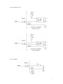
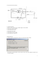
1
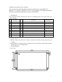
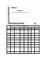
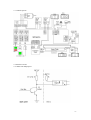
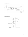
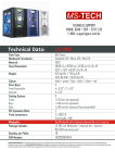
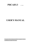
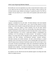
MPC6535 User Manual
V 1.3
MPC6535 improves major performance compared to MPC6515 in
(a). better motion control around the corner; and
(b). less interfering thanks to the aluminum case.
Leetro Automation Co., Ltd
Building 8-B, Dayi Zone of Incubating Hi-tech,
No.1 South 2nd Keyuan Road,
Chengdu 610041, CHINA
www.leetro.com
-1-
Thanks for choosing Leetro’
s product.
You are required to read through this manual carefully before using MPC6535.
MPC6535 is designed exclusively for the laser equipment. This high-performance
controller is based on the hardware solution of DSP+FPGA.
1. Packing List
Please check out the pack with below list. If there is something broken or lost, please contact you
supplier instantly.
No
Part Name
PCS
Description
Standrad/Optional
1
MPC6535
1
Controller board with Aluminum case
S
2
USB-AB-3M
1
Cable connected between PC and the MPC6535
S
3
PAD03-E
1
Operation panel with English interface
S
4
C4-PAD03-1.5M
1
Cable connected between PAD03 and the MPC6535
S
5
U-disk
1
USB flash memory disk
S
6
Dongle-white
1
LaserCut software key
S
7
STD-01
1
Single converter module (single-ended to differential)
O
8
PAD03-TR
1
Operation Panel with Turkish interface
O
9
PAD03-C
1
Operation panel with Chinese interface
O
2. Quick Start
2.1 Run the setup.exe and follow the “next step”instruction to install LaserCut program into your
computer.
2.2 Install MPC6535 controller board: mounting the board in the machine firmly. Must make the
machine house wires with GROUND!
3. Wiring Diagram
3.1 Size (mm)
-2-
3.2 Pins
Pin Definition
Group
1
2
3
4
5
Pow
+24V
24V GND
IN
Pedal
Switch
Cover
Opening
Protect
Water
Protect
24V
GND
+24V
Z_LIM
Z-axis
+Limit
Z-axis -Limit
Z-axis
Home
24V
GND
+24V
Y_LIM
Y-axis
+Limit
Y-axis
-Limit
Y-axis
Home
24V
GND
+24V
X_LIM
X-axis
+Limit
X-axis
-Limit
X-axis
Home
24V
GND
+24V
Z_AXIS
Z-axis
Pulse
Z-axis
Direction
+5V
Y_AXIS
Y-axis
Pulse
Y-axis
Direction
+5V
X_AXIS
X-axis
Pulse
X-axis
Direction
+5V
LASER
Analog1
Analog2
PWM+
PWM-
+Fire
Laser
OUT
Air-blow
Complete
Work
U-disk
Indicator
Reserved
24V
GND
6
7
-Fire
Laser
Laser
Power
Supply
GND
-3-
3.3 Control System
3.4 Interface Circuit
3.4.1 Pulse+Dir Output-port
-4-
3.4.2 IO Input-port Circuit
3.4.3 IO Output-port Circuit
-5-
3.4.4 Laser Firing Circuit
3.4.5 Laser PWM
-6-
3.4.6 Laser Power DAC Interface
3.5 Wiring Instruction
1. Must be careful with the positive and the negative end of 24VDC
2. Connecting controller and drive
3. Connecting Datum Switch
4. Connecting Limit Switch
5. Connecting laser power supply
6. Connecting other control ports
4. Tune and Test
4.1 run the program, name Mpc05Ver+M05.exe to check the version as below
The firmware version should be as same as DLL version. If not, please update. For details, refer
to LaseCut manual.
-7-
4.2 Run Lasercut53.exe for Settings:
A. Controller Type
B. Laser Power
C. Limit Datum Active Level
D. Pulse Equivalency
E. Working Table Size
F. Homing Direction
G. The Jerk is set as TEN times of the Acceleration
H. The turn acceleration is set as TWO times of acceleration
I. Tune for better performance
(for details, go to see LaserCut manual)
4.3 Download configure files and reset the control system
4.4 Input working files, edit the diagram, make the settings, download the file into controller
4.5 Start working.
5. Others
1. Must be careful with the positive and negative ends of MPC6535’
s power supply
2. Must turn the power off when disconnect the cable between control PAD and the board.
3. Make sure the metal case of MPC6535 wires to GROUND firmly
4. Setting pulse mode in the parameter for controller signal receiving
5. We recommend user take “LAS-”port for firing laser
6. Make sure the Dongle Serial Number (SN) matches the board SN
-8-