1
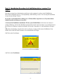
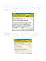
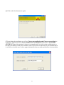
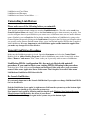
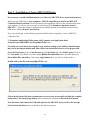
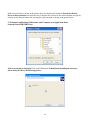
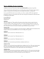
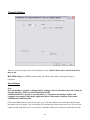
Link
Motion™
by Solustan, Inc.
Tel: 781-449-7666
Fax: 781-449-7759
support @solustan.com
User’s Manual
©Copyrights Reserved 2003-2010
1
SOFTWARE LICENSE AGREEMENT
YOU SHOULD CAREFULLY READ THE FOLLOWING TERMS. YOUR INSTALLATION OF THE PROGRAM
INDICATES YOUR ACCEPTANCE OF THESE LICENSE TERMS.
PLEASE READ THIS AGREEMENT CAREFULLY BEFORE INSTALLING THE PROGRAM. SOLUSTAN, INC.
WILL ONLY LICENSE THE PROGRAM TO YOU IF YOU FIRST ACCEPT THE TERMS OF THIS AGREEMENT
BY INSTALLING THE PROGRAM. SOLUSTAN, INC. PROVIDES THE SOFTWARE FOR TRIAL FOR 15 DAYS
OR 15 LAUNCHES OF THE DRIVER TO PROVE THE FUNCTIONING OF THE DRIVER ON YOUR PC BEFORE
PURCHASING THE LICENSE. ONCE THE LICENSE IS PURCHASED, IT IS NON-REFUNDABLE AND NONRETURNABLE.
These license terms apply to Your installation and use of the program, which program includes copyrighted materials
and programs (collectively referred to as "Program"). This license is granted to You by Solustan, Inc. You may not use
the Program contained in this Package to upgrade any existing Programs that You may have. The Programs contained in
this package are intended only for New Users of LinkMotion and/or MaxMotion and not for any other use.
1. License. This Program is licensed and not sold. Title to the Program does not pass to You. Solustan owns
copyrights in the Program. You obtain no rights other than those granted You under this Program License Agreement.
The term "Program" means the original (including any revisions, enhancements, updates, or the like) and all whole or
partial copies of it, including modified copies or portions merged into other programs. You are responsible for the use
of, and results obtained from the Program. This Program may be used only on one machine at any one time. You may
not reverse assemble or reverse compile the Program, except as specifically provided by law, without the possibility of a
contractual waiver. You may not sublicense, rent, lease, or assign the Program.
2. Disclaimer of Warranty and Limitation of Liability. THE PROGRAM AND ANY OTHER PRODUCT WHICH
WE PROVIDE TO YOU AS PART OF OUR SERVICE ARE PROVIDED "AS IS." EXCEPT AS SPECIFICALLY
SET FORTH HEREIN, NEITHER WE NOR OUR LICENSORS MAKE ANY WARRANTIES, REPRESENTATIONS
OR CONDITIONS OF MERCHANTABILITY, QUALITY, AND FITNESS FOR A PARTICULAR PURPOSE
RELATING TO OUR PROGRAM, SERVICES, AND/OR RELATED PRODUCTS THAT WE OR OUR LICENSORS
PROVIDE.
3. IN NO EVENT SHALL SOLUSTAN BE LIABLE FOR ANY DAMAGES RESULTING FROM THE USE OR
MISUSE OF THE SOFTWARE OR THE ACCOMPANYING MANUAL INCLUDING BUT NOT LIMITED TO
DAMAGES FOR INJURY TO ANY PERSON OR PROPERTY. THE PROGRAM IS DESIGNED TO WORK WITH
MACHINES AND AS SUCH, ANY PART OF THE SYSTEM MAY MISBEHAVE. IT IS IMPORTANT TO TAKE
ALL THE NECESSARY PRECAUTIONS IN OREDR TO AVOID EQUIPMENT DAMAGE AND/OR INJURY.
4. WE DISCLAIM ANY WARRANTY OF TITLE OR OTHER WARRANTIES FOR ANY THIRD PARTY'S
OFFERING(S) OR PRODUCT(S). ALL SUCH WARRANTIES AND REPRESENTATIONS ARE HEREBY
EXCLUDED. WITHOUT LIMITATION, NO WARRANTY IS GIVEN THAT THE PROGRAM OR PRODUCTS
ARE ERROR-FREE.
WE, INCLUDING OUR LICENSORS, DISCLAIM ANY LIABILITY OR RESPONSIBILITY ARISING FROM ANY
CLAIM THAT YOUR ACCESS OR USE OF THE PROGRAM, SERVICE, AND/OR RELATED PRODUCTS WE
PROVIDE INFRINGE ANY THIRD PARTY'S INTELLECTUAL PROPERTY RIGHTS.
IN NO EVENT ARE WE OR OUR LICENSORS ARE LIABLE FOR: A) DIRECT, SPECIAL, INDIRECT,
CONSEQUENTIAL OR INCIDENTAL DAMAGES EVEN IF WE HAVE BEEN ADVISED OF THE POSSIBILITY
THEREOF INCLUDING, BUT NOT LIMITED TO, LOST PROFITS, LOST BUSINESS REVENUE, OR FAILURE
TO REALIZE EXPECTED SAVINGS; OR, B) ANY CLAIMS AGAINST YOU BY ANY OTHER PARTY. This
Section applies to all claims by You irrespective of the cause of action underlying Your claim, including, but not limited
to: a) breach of contract, even if in the nature of a breach of condition or a fundamental term or a fundamental breach, or
b) tort including but not limited to negligence or misrepresentation.
2
In no event are We or Our dealers liable for any damages arising from Your failure to perform Your responsibility in
connection with this Program License Agreement, or arising from any cause beyond Our control, including but not
limited to delay in the performance of Our obligations or misuse of Your User IDs. All limitations and disclaimers stated
in this Section also apply to Our Product Licensors as intended beneficiaries of this Program License Agreement. Any
rights or limits stated herein are the maximum for which we are collectively responsible.
5. Termination. This license is effective until terminated. This license will terminate immediately without notice from
Solustan, Inc. if fail to comply with any of its provisions. Upon termination you must destroy the Software and all copies
thereof, and you may terminate this license anytime by doing so.
6. General. You are responsible for payment of any taxes, including Your personal property taxes, resulting from this
Program License Agreement or Your use of the Program. You agree to comply with all export laws and regulations.
Neither party may bring an action under this Program License Agreement more than ONE years after the cause of
actions arose. This Program License Agreement and all Your rights and obligations are governed by the laws of the
State of Massachusetts.
7. LinkMotion driver software is protected with a software protection key. The protection key is tied to your specific PC
computer using appropriate Microsoft Operating System. If the technology was not available to transfer the license to
another PC, you will be required to buy another license at a full price of the software in case of a PC failure beyond
normal repair. It is very important to safeguard the PC with the license.
8. LinkMotion driver software you purchased can also protected with optionally available hardware ID (dongle) key. If
the ID key fails for some reason, you could return it for replacement. As long as Solustan can identify the key to be the
one issued by us, we will replace it for a fee. On the other hand, if you lose the key, you will be required to buy another
license at a full price of the software. It is very important to safeguard the ID key.
Solustan, Inc. 165 Chestnut St., #200, Needham, MA 02492
Tel: 781-449-7666 Fax: 781-449-7759 EMail: [email protected]
3
LinkMotion Detail Installation and Setup Instructions
Computer Requirements:
Windows XP with Service Pak 2 or higher and Microsoft .NET 2.0 Framework installed,
USB 2.0 port, Processor speed of at least 800 Mhz, Minimum RAM memory 1 GB or more preferred,
60 MB of Hard drive free space, Screen resolution of at least 800 x 600,
CD-ROM drive is not required, if the driver software was down-loaded from the web site.
CD-ROM drive is necessary, if the software was received on a CD.
Second USB port if you bought Hardware key option.
Microsoft .NET 2.0 Framework is available for a free download from the following site:
Microsoft.com>Downloads & Trials>Download Center>.NET Framework Version 2.0 or
Higher.
If you have purchased Leetro controller without wiring you need to follow the instruction from the
document Connect Leetro controller first before you install any software.
LinkMotion version 2.6 or older required I.D. Key and the I.D. key driver. I.D. Key may be
provided as an option and user will need to load the I.D. key driver and we can send instructions
separately. Do not worry about loading the driver for the key if you did not receive any hardware
I.D. key.
Installation required for LinkMotion for USB:
Part 1 - Driver for the USB I.D.key (Dongle) is necessary to install only if you purchased hardware
key option. Your LinkMotion CD will install this part first. If you had intalled a demo version of
LinkMotion before you received this version you do need to uninstall LinkMotion and then Re-Install
from the CD received with the hard ware key.
Part 2 - Second part is Installation of LinkMotion driver software for Leetro MPC6515 Laser.
Part 3 - Installation of Leetro Controller driver. This should be done only after you install
LinkMotion driver software.
Part 4 - Initialize of Leetro Controller. This should be done only after you install LinkMotion driver
software and connect Leetro Controller to the computer where you have loaded LinkMotion driver.
Part 5 - Software License Code procedure is necessary to follow if you already purchased
LinkMotion driver software without the hardware key.
4
Part 1 – Hardware key (dongle) Driver:
This is necessary to install only if you purchased this optional item. If you had a demo version of
our software that was installed on the same computer please make sure to uninstall that version
and then continue this procedure. Your CD should start installing this part first.
Keep the ID key handy but do not plug it in yet. First you will be asked if you would like to install
software for the I.D. Key. Click on the Yes button if you are installing for the first time. You can click
on the no button if you are only reinstalling LinkMotion to by pass this procedure. Follow the on-screen
instructions. Choose full installation when you see that option on the screen and after you agree to
standard software license procedure and it should finish driver installation for the hardware key. It will
install Sentinal Protection Installer 7.4.0. Please get in touch with us if you need more help.
5
Part 2 - Installation Procedure for LinkMotion driver version 2.7 or
higher:
Note that you must have administrative privileges on the computer in order to install LinkMotion.
Most of the installation process is self-explanatory with following screens. You can stop the installation
at any time by clicking "Cancel".
If you have received the driver software on a CD then follow steps from (1A). If you have down
loaded form the web then go to step (1B).
(1A) Insert the LinkMotion installation CD into your CD-ROM drive. If the Auto-run feature is
enabled, Windows will start the Installation automatically. If the Auto-run feature is not enabled, browse
the CD drive in Windows explorer and double-click on the "Launcher.exe" and installation will begin.
or
(1B) After downloading, unzip the files and save them by creating a folder name LinkMotion. Now
double click on the file name Launcher.exe and installation will begin.
(2) Click on the Next Button.
(3) Click on the Next Button.
6
(4) When you get to the License Agreement dialog (see above), you must read the agreement. If you
agree, go ahead and click the radio button, "I Agree" for the installation process to continue. Then
Click on the Next Button.
(5) After you have read and agreed to the License Agreement, you will be asked to specify the
installation folder. In most cases you can leave this at the default value. You will also be asked to
specify who will be able to run LinkMotion on this computer. In most cases you should specify
"Everyone" and then Click on Next button.
7
(6) Click on the Next button once again.
(7) Later during the installation you will see Choose your application and Choose your machine for
installation. Application name is Laser machines for V/C and board and machine is Leetro MPC
6515 PWM. Name of the machine is shown as an example and if you click on the scrolling arrow on
the right you should see many more machines listed. If you do not see the name of your machine then it
is easy for us to include once we have proper information from you with specifications of your machine.
8
(8) During installation, if a dialog pops up warning you that you are installing an untested driver, click
on "continue anyway". This warning will be removed in a future release.
(9) Click on "Close" when the installation is complete.
9
Icon shown above should show up in system tray at the bottom right.
(10) Setting up the Default Printer:
You want the LinkMotion printer to be your default printer. Go to the Start button and open the "Control
Panel>Printers and Faxes" menu and find the printer driver with Leetro MPC6515-PWM name as
shown in the picture below. Right click on this printer and select "Set as Default Printer".
Installation procedure is complete.
Now refer to Using LinkMotion and the design application you are using and how that works with
LinkMotion and Popular Applications. Document names are as following:
10
LinkMotion and Corel Draw
LinkMotion and Illustrator
LinkMotion and Auto Cad and More …….
Uninstalling LinkMotion:
Please make sure of the following before you uninstall:
Your specific machine related settings are saved as LinkMotion.ini file. This file can be saved from
General Options Menu and simply click on the Save button and give whatever name you prefer. You
can also navigate where in your hard drive you want to save it. Different users can save under different
names. Similarly you can Load that file back after another installation of LinkMotion by going to the
General Options menu and clicking on the Load button. Navigate to the file from your computer where
you saved it earlier. Restore Default button allows you to load default installed INI file that is supplied
with LinkMotion. It is very important to exit LinkMotion applet and Re-launch the applet when
you make any changes for it to be effective.
Uninstall LinkMotion Procedure:
Make sure the LinkMotion applet is closed. Open the Start menu and select the Control Panel.
Double-click on Add or Remove Programs. Look for LinkMotion entry in the list and click on that.
Select "Remove" and answer "Yes" when it asks you if you really want to remove LinkMotion.
LinkMotion.INI file (configuration file) does not get deleted with uninstall
procedure. If you want to delete your existing INI file following is the procedure:
In the hard drive Find folder name Document and Settings> Folder with users (your own name)
name> Folder name Application Data> Folder name Total Graphics Network> Folder name
LinkMotion> LinkMotion.INI. Delete this file.
Re-Launch LinkMotion:
It is extremely important to Re-Launch LinkMotion if you replace or change LinkMotion.INI file
for it to be effective.
Exit the LinkMotion (icon) applet by right mouse click from the systems tray at the bottom right.
LinkMotion icon should go away from the systems tray.
Now launch it back again by following and selecting the path Windows Start button>Program
Files>Solustan>LinkMotion by the arrow of your mouse.
LinkMotion icon should appear again in the systems tray at the bottom right.
11
Part 3 – Installation of Leetro MPC6515 Driver:
It is necessary to install LinkMotion before you follow the MPC6515 driver instruction from here.
When you plug USB cable to your computer’s USB 2.0 compatible port and Leetro MPC6515
Controller board is attached it will be looking for the appropriate driver for this controller board into
your windows. It will give you a message at your bottom right “Found new hardware Leetro’s
MPC6515 ”. Ignore the windows automatic driver installer program for installation of the Leetro’s
USB driver. Simply click on Cancel button.
Now you can navigate to the following path and install the driver required by Leetro’s MPC6515
Controller Card.
C:\Documents and Settings\Folder name with Computer user\Application Data\
Solustan\LeetroUSB\USB Driver\SetupMpc6515Drv.exe.
(If you do not see the above shown path in your windows settings, your windows default settings
may not be showing the hidden path. Please follow the instruction below to see the proper path.
Go to the Start button. Select Control Panel. Select Tools Menu and select Folder option. Click on
the View menu. You should see a folder called Hidden files and folders. Here select the button for
Show hidden files and folders. Click on the Apply button. Now you will see all the folders.)
Double click on the file name SetupMpc6515Drv.exe.
Follow the direction of the driver manufacturer as seen on the screen until you finish the complete
instructions. Click on the Setup button. After it finishes the installation click on the Exit button.
Now disconnect and connect the USB cable again for the MPC6515 and you will see the message
for Found new hardware and you should see the following picture.
12
Select the button for Install from a list or specific location (Advanced). Click on the Next button.
13
Make your selection as shown in the picture above by checking the button for Search for the best
driver in these locations and check the box for Include this location in the search and then navigate by
clicking on the Browse button and selecting the following path as shown in the picture below.
C:\Documents and Settings\Folder name with Computer user\Application Data\
Solustan\LeetroUSB\USB Driver.
After you navigate to this path Click on the OK button. It should start installing the necessary
driver and you will see the following picture.
14
While it is installing the driver you will also see the message from Microsoft regarding the driver
and it is safe and you should click on the button for Continue anyway.
Once it is done installing at the end you need to click on the Finish button and you are done with
the driver installation for Leetro MPC6515.
Last procedure is to Re-Launch LinkMotion application:
Bring the arrow of your mouse to the bottom right where LinkMotion applet is on the system tray
And click with the right mouse button and select Exit. This will exit LinkMotion application. Go
to the start button on the left and select All Programs>Solustan>LinkMotion. Now Linkmotion
should be launched again and you should see the LinkMotion applet at the bottom right in the
system tray.
Once the driver is installed there will be communication between the LinkMotion and your
Leetro’s MPC6515 controller.
Replacing .dll file:
There are .dll files that may be different for different version of Leetro’s controllers. We have provided
different folders with different version of .dll files on your LinkMotion CD. LinkMotion installs this .dll
files in the following are and you can simply replace this by windows copy and paste command.
C:/Program Files/Solustan/LinkMotion/Leetro/mpc05ls.dll (this file should be replaced)
C:/Program Files/Solustan/LinkMotion/Leetro/CommM05.dll (this file is common and may not
need to be replaced)
15
Part 4 – Initialize of Leetro Controller:
LinkMotion for Leetro 6515 provides a button named INITIALIZE in the Laser Control Tab.
You can click the button and bring the laser to its initial settings anytime. The initial settings require a
number of settings based on the design of the laser machine the controller is working with.
If you open the INI file for the Leetro controller, you will see a number of SET values right in the
beginning for settings of your machine name. Here is the description of the different values that need to
be initialized for the machine.
[Leetro MPC6515]
name=LeetroUSB
BoardType=10
SET001=0
(The value can be 0 or 3. The controller will generate analog voltage for power control when 0 is
declared for SET001. Most Chinese glass tubes for laser power generation require this setting. The
controller will generate variable PWM pulses when 3 is declared for SET001. Typical American laser
tubes like Synrad, Universal, Coherent, and others require PWM for laser power control.
SET002=25000
(The PWM pulses need to be generated at a prescribed frequency. SET002 require the declaration of the
frequency in Hz. If you declare SET001 to be zero, this setting will be ignored.)
SET003=4
(SET003 is used to set the X axis. The default value is 4.)
SET004=3
(SET003 is used to set the Y axis. The default value is 3.)
SET005=2
(SET003 is used to set the Z axis. The default value is 2.)
SET006=0
(SET006 is used to declare the top left absolute coordinate in the X axis.)
SET007=151300
(SET007 is used to declare the bottom right absolute coordinate in the X axis. The actual value declared
here is the actual number of step commands issued to the X axis step motor to get to the end of the
working area from left absolute zero to the right absolute and of the working area.)
SET008=100866
(SET008 is used to declare the top left absolute coordinate in the Y axis. The actual value declared here
is the actual number of step commands issued to the Y axis step motor to get to the end of the working
area from bottom absolute zero to the top absolute and of the working area.)
16
SET009=0
(SET009 is used to declare the bottom absolute coordinate in the Y axis. The absolute zero turns out to
be bottom left and the absolute maximum values in the X and Y axis is top right.)
SET010=-15686
(SET010 is used to set the negative value below the reference zero point in the Z axis. The actual value
declared here is the actual number of step commands issued to the Z axis step motor to get to the bottom
most point from the reference zero point. The reference point is typically the top surface of the material
to be worked on.)
SET011=15686
(SET011 is used to set the positive value above the reference zero point in the Z axis. The actual value
declared here is the actual number of step commands issued to the Z axis step motor to get to the top
most point from the reference zero point. The reference point is typically the top surface of the material
to be worked on.)
SET012=0
(SET012 can be 0 or 1. It declares the polarity of the Home switches when they are active. If there are
Home switches in all three axis, all three need to have similar polarity. A declaration of zero defines
logic low to be true when activated. A declaration of 1 defines logic high to be true when activated.)
SET013=0
(SET)13 can 0 or 1. If the user wants the machine to automatically seek home when power to the
machine is turned ON, set the value to be 1. Otherwise, set the value to zero.)
SET014=1,0,2,0
(SET014 allows setting of the backlash compensation. Value 1 is set for X axis followed by a number in
terms of number of step commands to the X axis motor for backlash compensation. Value 2 is set for Y
axis followed by a number in terms of number of step commands to the Y axis motor for backlash
compensation.)
SET015=1,252.00,2,252.00,3,252.00
(SET015 sets the resolution for each of the axis. 1 for the X axis followed by the value, number of step
commands to the X axis motor to travel 1 millimeter. 2 for the Y axis followed by the value, number of
step commands to the Y axis motor to travel 1 millimeter. 3 for the Z axis followed by the value, number
of step commands to the Z axis motor to travel 1 millimeter. You are allowed to use decimal places to
guarantee precision.)
SET016=1000
(SET002 sets up frequency for PWM operation. SET016 sets up frequency for tickle pulse generation.
You could have the same or different frequency for PWM operation and tickle pulse. Even if it is the
same, you do need to set up SET016. Valid range for SET016 is 100 Hz to 200000 Hz. If you happen to
own a laser tube that requires PWM for power control but generates its own tickle pulse, you could
declare SET016 and SET017 to be zero.)
17
SET017=10
(SET017 sets up tickle pulse duty cycle. Typically, American manufacturers require 1 percent pulse
width for tickle pulse. Please, refer to the manufacturer’s specifications. It needs to be declared in actual
frequency cycle value.)
SET018=0
(This is reserved for future use.)
SET019=1,1,0
(SET019 sets up compensation in power for distance in laser beam from its start position. The setting
assumes that the job starts from the Home position for the controller to calculate compensation for the
distance.
The first value is for X axis. If laser beam is coming from the left of the X axis, this value shall be zero.
If the laser beam is coming from the right side of the X axis, this value shall be 1.
The second value is for Y axis. If laser beam is coming from the top side of the Y axis, this value shall
be 1. If the laser beam is coming from the bottom side of the Y axis, this value shall be 0.
The third value is the actual compensation. The range is 0 to 10000 instead of 0 to 100 percent to be
more accurate.)
Configure your machine for total working area in LinkMotion.INI file. In LinkMotion.INI file you need
to enter the value in inches. For example your working area is X=1250 mm and Y=900 mm for which
you need to enter following values in the LinkMotion.INI file.
XTableSize=50
YTableSize=36
Save this file once you make all the changes with proper numbers.
Re-Launch LinkMotion and go to the Laser Control Tab and click INITIALIZE. Your controller should
have been powered up and properly connected to the USB port. The new configuration file for your
machine will be sent down to the controller.
Go to the Controller pad, bring up the configuration file and RUN it. This will reconfigure your
controller.
18
Part 5 – Software License Key Procedure:
We welcome you for trying out our LinkMotion driver software. You will see the following message on
the screen when LinkMotion is launched from the systems tray every time when you are using the
program as demo. This procedure is not needed for the customers who purchased optional hardware key.
If you did not purchase within 15 days or 15 launchings you will see a last reminder as seen in the
following picture. It will be best to purchase at this point.
Once the trial period of LinkMotion expires, you will see the following message.
Click on the Enter key button, whenever you decide to purchase.
19
Once purchased LinkMotion, you need to provide us the proper information for Hardware fingerprint,
Name of your Business and valid email for Business. Fill out this information in each respective
boxes, save it and email it to us at [email protected]. We recommend for you to use copy and paste
method so there are no errors. Solustan is not responsible for any incorrect Hardware fingerprint code
you provide. Please double check this information before you send it to us. Software license working
with Hardware fingerprint and matching code provided by Solustan, Inc. is intended to work only on the
computer with the proper hardware fingerprint.
After you send us this information we will send you the customized Key Code. This key code is long
text containing numeric numbers as well as alphabet letters. We highly recommend that you simply
copy and paste this by bringing back the same Enter Key screen. Click OK and you are ready to use
your LinkMotion driver software.
Hardware fingerprint:
Business Name:
Valid email for Business:
Key Code:
20
LinkMotion for Leetro 6515 controller for CO2 laser:
Important Laser Warning:
Solustan is the provider of control software for your laser power based equipment. Extreme caution
shall be applied in the use of the machines. Proper safety equipment shall be installed and properly
tested to make sure that in case of a failure either in the functioning of the Solustan provided software or
other software or the computer hardware associated with the software, proper and safe shut down of the
laser power takes place automatically.
This is simply a guideline and not an all-encompassing document for safety and precaution. It is the
responsibility of the laser system integrator to make sure that all the safety requirements are met to meet
the letter of the law and additional considerations for human safety.
Machine use and Safety:
Buyer acknowledges that the seller does not know of the specific application of said equipment by the
buyer, therefore, it is the buyer’s (user’s) responsibility to provide proper safety devices and equipment
to safeguard the operator from harm for any particular use, operation, or set up, and to adequately
safeguard the machine or machines to conform to all federal, state and local government safety standards
and all industry safety standards, including, without limitation, the 1970 Occupational Health and Safety
Act, as amended (“OSHA”) and ANSI Z136.1-2001 Safe Use of Laser Standard.
Indemnification:
Buyer agrees to indemnify, hold harmless and defend Seller from and against any and all claims,
liabilities or lawsuits involving injury or accident occasioned by Buyer’s use of said equipment. This
agreement includes but is not limited to the duty to indemnify, hold harmless and defend seller in any of
the following: (1) Claim involving or alleging improper or negligent maintenance, reconstruction, repair,
alteration, or modifications of the equipment by the buyer, its agents or employees: (2) Claims involving
allegations of failure, negligent or otherwise, by the buyer, its agents or employees, to follow Seller’s
instructions, warnings or recommendations, or to equip said equipment with safety devices as required
by federal, state or local government statutes, rules or regulations (including “OSHA” and ANSI
Z136.1-2001 Safe Use of Lasers Standard), or as is customary in the trade.
Safety:
Tests carried out have proved the safety and reliability of the laser when used properly. The operator
should nevertheless be aware of all the necessary safety rules in order to avoid any risk of damage to
persons or the equipment itself.
Laser Radiation:
The Solustan software employed to work with any laser system is an OEM system (original Equipment
manufacturer), which means that it has been designed and developed as an individual component to be
integrated into more complex systems. As an OEM component, it has not been fitted with all the safety
systems that complete a laser system. Specialized technicians will need to connect up the machine with
all the interlocks, safety indicators and protection devices.
21
Laser radiation is an electromagnetic emission with a micrometric wavelength found in far infrared
(CO2 Laser), near infrared (Nd:Yag, Nd:YV04 Laser), visible (He:Ne or Argon Laser), and ultraviolet
(ecchymer lasers).
It should be considered non lonogenic Radiation. In many laser machines, the emission of a crystal bar
is excited by “optical pumping” generated by powerful Laser Diode. The continuous bouncing of
Photons between a front and a rear mirror sets up a positive reaction and so their numbers increase by
the instant, until the required concentration is achieved to produce a collimated beam emitted from the
semi-reflective front mirror. The radiation (which we can imagine to be a “Beam of invisible light”) is
then Focused by means of Lenses on a point where the intensity becomes so great that it can react with
different materials to cause an alteration by thermal effect.
Even though the radiation of many of such Laser machines may be invisible, because it is near the
threshold of vision, the Eye receives it virtually integrally without even any papillary reflex! If we take
into account that this is generally very intense, it follows that it can be extremely damaging or lethal to
the eyesight.
Note:
Looking directly at a laser beam can cause irreversible damage to the eyesight.
To avoid permanent personal injury, certain precautions must be followed. All persons who may be
exposed to dangerous levels of laser radiation, must know when the laser is active, in which case they
must wear protective glasses.
The laser integrated in the Yag system, because of its high power, causes laser light to be reflected from
flat surfaces. This reflected light is potentially dangerous to the eyes and skin. Electromagnetic emission
with micrometric wavelength comes within the far infrared range and is therefore invisible, it is
therefore not obvious where these reflected beams are directed.
Note:
Protection from reflected light beams is essential, because these can be of sufficient intensity to cause
permanent damage to the eyes and to the skin.
In addition to the potential damage to eyes, invisible laser emission can burn clothes and other
flammable materials such as organic solvents (alcohol, acetone) or benzines.
Note:
Every laser system is designed as a particular class system. The system integrator shall understand and
document the appropriate class of the device, label it properly and explain the importance of safety to
the user organization personnel. Class IV covers all laser which are hazardous, not just because of direct
or reflected radiation, but also because of diffused radiation! These laser sources can be particularly
dangerous to the skin and represent a fire hazard for flammable materials.
22
System Requirements:
The LinkMotion driver comes with a small application that resides in the System Tray. The System Tray
is the lower right bar of the Windows screen. Double click on the LinkMotion icon to bring up the
application.
Your computer should have Windows XP operating system with Service Pak 2 (SP 2) installed and
two USB connections. Also you should install Microsoft .NET Framework Version 2.0. This is
available form Microsoft’s web site for you to download freely:
Microsoft.com>Downloads & Trials>Download Center>.NET Framework Version 2.0
If you can afford it, get 2 , 3 or 4 GB RAM memory in your PC in order to process large engrave
jobs at high resolutions in the most efficient manner.
Vector and Raster preparations:
Vector (cut) jobs: Zero or thinnest line width and No fill are the most important things to
remember when you are designing a file to send to a machine for the vector (cutting) output.
Raster (engrave) jobs: It is NOT NECESSARY to create jobs with the thinnest line widths and
NOT NECESSARY to unfill shapes before sending the jobs for processing in case of raster
(engrave) output.
LinkMotion.INI file can be found as follows:
In the hard drive Find folder name Document and Settings> Folder with user’s(your own or business
name) name> Folder name - Application Data> Folder name - Solustan> Folder name LinkMotion> File name - LinkMotion.INI
Open LinkMotion.INI file by double clicking on the file. It is a text file. You will see all the
different machine names at the beginning. Specific machine related controls are further down in
the file. Find the specific settings for your machine and you can make changes there. Remember to
save the file after you make changes.
Also, remember to Re-Launch LinkMotion for your changes to take effect.
23
Material Properties:
Pull down the Material Properties menu to observe a selection of various materials. Pre-select the
values for speeds for each of the materials. Tool Speed has two different sections Cut/Vector Speed
and Engrave/Raster Speed. These speeds are associated with what you select in the Laser Control
Menu (tab) Vector or Bitmap. Cut/Vector Speed is associated with Vector selection.
Engrave/Raster Speed is associated with Bitmap selection. LinkMotion can be employed to work
with many different types of materials. Hence, there is no single value appropriate for all different
mterials. User’s experience will dictate the values for his/her machines.
The values can be inches per second or millimeters per second or centimeters per second. General
Options menu allows you to make your selection for this measure of units.
Vector Jobs can be designed in color and speeds can be defined as percentage of declared values for
each of the colors. One of the applications of this feature is to design the same job in different colors on
different layers and sequence the layers appropriately.
Different material selection and the flexibility of different speed settings are available here. You can add
more materials by going into the LinkMotion.INI file and create your own list in the material section.
Color selection in your design application will effect the output power and the speed as you see in the
24
above chart. Make these selections ahead of time and simply click on the Apply button and they
become effective.
Following are the color/pen values for the LinkMotion printer driver. RGB values are given in percent.
Pen number
--------------1
2
3
4
5
6
7
8
9
10
Color
-------Black
Red
Green
Blue
Cyan
Magenta
Yellow
Orange
Brown
Purple
R
--0
255
0
0
0
255
255
255
128
128
G
--0
0
255
0
255
0
255
128
0
0
B
--0
0
0
255
255
255
0
0
0
128
If you did not create a color palette with the above RGB values, our understanding of the way GDI
handles this is that GDI will convert the object's color to an RGB value using whatever color correction
model is in effect, then will do a least-squares fit to the 10-color palette (whichever of the 10 colors is
closest to the color of the object on a least-squares bases will be the color that is sent to the printer
driver). It is best if you can create your own palette in the job design program of your choice with the
above selected colors to get the best results.
Cut/Vector Speed or Engrave/Raster Speed is the speed when the laser is on and working. Bringing
your arrow on the number that shows Mark Speed (100%) or Power (20%) for each pen and Double
clicking on the number should open a box that will allow you to change this number. If your Cut/Vector
Speed or Engrave/Raster Speed is 2in/sec and you make the red pen to give output at 50% then job
should run at 1in/sec.
25
Laser Control:
This is the most important part of the settings and selections in LinkMotion for proper output from your
lasers system. LinkMotion is a printer type driver and user will spend most of the time designing a job in
his/her favorite application program. However, settings and selections here prepare the laser machine for
proper output in the intended location on the laser machine.
Laser Output Controls
When Laser On button is checked the job will be processed with the laser power on. Laser on or off can
be checked by checking this button.
Red Pointer On is also effective in the same manner if your machine is equipped with one and connected
properly.
26
Laser Operating Frequency
CO2 laser tubes manufactured by different manufacturers may produce different results at different
frequency on different materials. Please, review the suggestions made by the laser tube and the laser
machine manufacturers to enter proper frequency values for the job at hand. The frequency information
will be sent along with the job to the laser machine for the proper execution of the job.
Output Type - Vector or Bitmap or Gray Scale (near future) output
Selection of Vector or Bitmap mode is checked depending on your design. The Vector mode is also
referred to as Cut mode and Bitmap mode is also sometimes referred to as Engrave mode.
Vector mode
Vector mode is used to cut or score materials. Appropriate speed combined with the selection of the
power is required. The values will be different for different materials and desired results.
The speed of the laser beam movement is declared in the Materials Menu and can be preset for different
materials ahead of time. The speed values are typically inches per second or millimeters per second.
The power value is set from 0 to 100 percent of the available laser power in the machine.
Please, refer to our documents for the job preparation in many different popular applications.
If the application is capable, the jobs can be designed in different colors for vector operations. Different
speeds and power levels can be set for different colors within the same job.
There are two additional settings required to be set in the Vector mode:
1. Percent of maximum speed at start
Going from zero to maximum speed instantaneously may result in loss of steps by the motors.
Manufacturers will provide proper number that will allow the system to ramp up the speed to the desired
cutting speed. In absence of any specific information, a conservative number like 5 or 10 percent may be
functional.
2. Percent of Maximum power at corners
LinkMotion and the controller realize that the laser beam movement needs to slow down when either of
the axis (X or Y) is taking sharp turns. This setting allows the reduction of power along with the speed
to reduce or eliminate the burning of the corners. If the power is not reduced, the same power will be
applied to the material while the beam is moving slower at the corners.
Please, experiment with different values to arrive at proper numbers for your materials.
27
Bitmap mode
Bitmap mode requires for you to select the proper DPI (dots per inch) resolution. Remember to
understand different speed settings for Bitmap work and Vector work. Vector will require slower
speed and bitmap (raster) can be driven at a higher speed settings. Speed will depend on the motors
and design of your machine.
The raster and vector modes are equally important in the laser machines. It is these two modes that make
laser machines very versatile for different operations.
However, the raster work is different. It is very important to do error diffusion dithering for raster
jobs. The files are bigger describing every pixel, its position and whether the laser power is on or off for
that pixel. It is important to know that the PC should be equipped with adequate amount of RAM
memory. First of all, Windows requires lots of memory. Secondly, your application is going to require
some memory.
There are two additional settings required in the Raster mode:
1. Percent of maximum speed at start
Going from zero to maximum speed instantaneously may result in loss of steps by the motors.
Manufacturers will provide proper number that will allow the system to ramp up the speed to the desired
cutting speed. In absence of any specific information, a conservative number like 5 or 10 percent may be
functional.
2. Selection of the resolution (DPI)
LinkMotion calculates and provides many choices for DPI settings in the user interface. It will also tell
you the exact output size compared to the actual size designed in your application. This is necessary
because machines built with step motors work at certain microsteps. Also, the belt driven or screw
driven systems have its own resolution in terms of linear distance traveled per revolution of the step
motor. The system cannot take any fractional steps more than the available microsteps in the system.
LinkMotion will calculate and preset to the user available resolutions for either exact size or sizes vary
close to the actual design size. Select the resolution of your choice.
How to rasterize job quickly
If you design a raster job in a job design program with the page size equivalent to the total working area
of the machine and if your job happens to be lot smaller compared to the total working area of the table,
the job design program will take long time to raster the complete page for rastering every dot.
LinkMotion driver will remove the unnecessary area of the job. The following procedure can be
implemented easily to reduce the time to rasterize the job by the job design program.
28
If you are planning to design a very large engrave job and are also planning to process it at a high
resolution, make sure you have adequate RAM memory in the PC to handle the job in RAM memory
only. In case of inadequate RAM memory, the Windows will start to use hard disk drive while
rasterizing. Time to process the job will go up exponentially.
If your table size is very large, e.g. 48 inch X 48 inch and you are working with an engrave job of 12 X
6 inches, You position the material wherever convenient on the machine.
Define the size of the working area in LinkMotion to be the same as your engrave job 12 X 8 inches.
Reload LinkMotion.
Reload your application for it to get the latest information of the new size of the table.
Create the same area of 12 X 6 on your job design screen to match with the new maximum travel area in
the Machine Properties Tab in LinkMotion.
Select Material Bounds in the Laser Control Tab.
Select starting position in the Laser Control Tab.
Jog your laser beam to the same starting position on the corner of the material.
It will be quick to create the raster job and it will take less memory to save the job and it will take less
over all time to process the job.
Output Boundaries
This is an important area to understand the positioning of the job on the working area of the laser
machine.
Following settings play part in positioning the job on the machine:
1. Actual working area of the laser machine
2. Working area in the job design program
3. Maximum travel area declared in the Machine Properties in LinkMotion
4. Selection of the Output Boundaries and Starting Position in the Laser Control area in LinkMotion
Rule no. 1 – the working area in the job design program and maximum travel area declared in the
Machine Properties should always be the same before sending the job to the laser machine.
Rule no. 2 – You should always re-launch the job design application if you change the maximum travel
area declared in the Machine Properties. The job design application picks up the information about the
maximum travel area from the LinkMotion driver at the time it launches.
There are three selections in the Output Boundaries in the Laser Control section;
- Logical Home
- Job Bounds
- Material Bounds
Logical Home
29
The machine should be equipped with Home switches for the selection of Logical Home. Typically,
when the machine is sent Home, the laser beam will park itself at the right top corner of the working
area. This is also defined as the (Xmax, Ymax) locations in absolute coordinates.
The bottom left corner of the working area is defined as (X0, Y0) location in absolute coordinates.
All the starting position selections are grayed out in the Laser Control Tab when logical home is selected
because it is not necessary to select one.
Total working area in the job design program
At this point, you may have set up the working area in the job design program and the maximum travel
area in the Machine Properties in LinkMotion to be the same as the working area of the machine.
If the job is sent to the machine, it will be processed exactly at the same position on the machine as the
actual design position on the job design program.
Less than total working area in the job design program
At this point, you may have set up the working area in the job design program and the maximum travel
area in the Machine Properties in LinkMotion to be the same. However, this value is less than the total
working area of the machine.
The lower left of the job design program screen is considered to be (X0, Y0). This is the same as the
lower left point on the machine (X0, Y0). The job will be processed with respect to the lower left
positions.
LinkMotion will calculate and will show the maximum multiple copies possible in X and Y axis.
Job Bounds
Job Bounds and the Material Bounds should be considered together for better understanding. Logical
Home selection always takes you to the absolute positions on the table. Please, note that when Logical
Home is selected as the output boundary, none of the starting positions are available for selections. It
will simply process the job in its right place.
Select either Job Bounds or Material Bounds and you have nine starting positions to select from.
30
Above is a job designed in Corel Draw job design program.
Note the plate size and it could easily be the material size of 8 in X 6 in.
The job itself is smaller and designed inside the plate. Note that the job is bound by 8 black square dots.
This bounding box is what we are referring to the job bound box. Compare the eight bounding dots plus
the X mark in the center to the nine starting positions in the Laser Control Tab of LinkMotion.
Position the laser beam under your material where you want to start at one of the nine positions and
select the same starting position in the Laser Control Tab. The job will start from that point of the
bounding box.
31
Material Bounds
Material Bounds and the Job Bounds should be considered together for better understanding. Logical
Home selection always takes you to the absolute positions on the table. Please, note that when Logical
Home is selected as the output boundary, none of the starting positions are available for selections. It
will simply process the job in its right place.
Select either Material Bounds or Job Bounds and you have nine starting positions to select from.
Above is a job designed in Corel Draw job design program.
Note the plate size and it could easily be the material size of 8 in X 6 in.
Position your material of the same size wherever you want on the machine. Position the laser beam at
one of the nine starting positions of the material. Select the same starting position in the Laser Control
32
Tab. The job will start from that point of the material and it will be placed in the same relative position
on the material as it is on the screen.
Downloaded File Management:
The bottom right area of the Laser Control Tab shows the names and size of the files existing on the
Leetro controller. The controller can be initialized anytime with original settings for the machine.
LinkMotion driver will try to inquire with the Leetro 6515 controller for an existing list of job files when
the user clicks on the Laser Control tab. If the communication is not established between the PC and the
controller, the controller DLL will respond with an error message for the communication malfunction.
There are many possible reasons for the communication malfunction:
1. Windows operating system temporarily suspends USB devices if they are not used and dormant for a
period of time.
2. Windows screen savers creates interruptions in USB communication from time to time.
3. If for some reason, USB interface cable between the controller and the PC were removed or came
loose, communication will be interrupted. Upon connecting back, Windows will recognize the device.
However, LinkMotion driver needs to be launched again to establish the communication with the
controller. Right click on the LinkMotion icon in the system tray and select EXIT. Go to the Start button
in Windows and re-launch LinkMotion.
If the communication is properly established, the lower right area in the Laser Control tab will show a
list of existing files on the controller memory. Single file can be deleted by selecting a file and click on
Delete or all job files can be deleted by selecting Delete All command. If LinkMotion does not find any
job files, it will report - No files have been found.
User cannot select and execute a job from this list in the LinkMotion user interface. The user is required
to select the job on the ControlPad on the laser machine to execute the job.
Your laser machine was properly Initialized by the laser machine manufacturer. All the necessary
settings are saved in LinkMotion. If necessary, the laser machine and its controller can be re-initialized
by clikcing the INITIALIZE button.
Multiple Copies
Whenever the plate size in the job design program along with the same declaration in the Machine
Properties Tab is smaller than the total working area of the machine, multiple copies area will inform
you of the maximum copies can be made in each of the X axis (across or horizontally) and Y axis (down
or vertically). User can insert as many copies as required in each of the axis. Total working area is
declared in inches(do not write mm values) in the LinkMotion.INI file under Leetro MPC 6515 there
are following lines.
XMaxTravel=24.00
33
YMaxTravel=18.00
If you design your plate size to be 4”x3” you can get 6 multiple copies across and 6 down. This numbers
are given as an example.
Bitmap jobs (Raster jobs) will be concatenated horizontally to speed up the job processing and reduce
the total job time. Vector jobs will be processed one at a time.
34
Machine properties:
Z axis can be selected as motorized or air controlled. For Leetro implementation, it should always be
checked. The Leetro controller handles the movement of the Z axis step motor.
If Enable I/O control 3 is checked, it will turn on and off with the job execution.
If Enable I/O control 4 (Spindle/Air) is checked, it will turn on and off with the job execution. The
value of delay can be entered in seconds and fraction of seconds in the Spindle Delay area. This
delay value will allow the spindle motor to reach its speed before the tool plunges into the material.
35
The maximum travel distances of the machine in X, Y and Z axis is shown here. The maximum
travel numbers (in other words the size of the table) should match the Design applications you are using
like Corel Draw or Auto Cad for the job to appear in the expected place on the machine. Laser raster
work may require for you to declare smaller X and Y travel area for you to get your job done quickly.
Refer to the Laser Control explanation in earlier section for what size you should declare.
Linear travel per revolution (lead screw pitch) is shown here and you can change this if necessary.
There are unknowns in a system from time to time. These are the pitch of the screw (2 turns per inch, 5
turns per inch, etc.), full step angle of a step motor (200 full steps for 360 degree turn, etc.), and micro
stepping of the driver. Make the necessary correction of the value for the unknown parameter until you
get the desired distance of travel.
Cylindrical axis choices will be offered if the machine is equipped with it. It is very important to quit
and Re-launch LinkMotion applet after you make this selection. Maximum Travel size of the table
in X or Y will change when you Enable Cylindrical Axis Support. You do not need to enter this
new size in Maximum Travel area in LinkMotion applet. However, it is very important to
remember the dimensions and create that Table size in your design applications like Corel or Cad.
Selecting X or Y whichever is the cylindrical axis for your machine. Motor Gear Ratio and Job Piece
Diameter is entered for your job in the bottom section.
36
Motor Parameters:
Above values are determined by the motor manufacturer. Enter Full steps per revolution values for
each axis depending upon the motor and the lead screw size specifications.
Declare Toolhead Maximum Acceleration values for the motors in each of the axis in in/seec^2. You
may need to adjust this numbers to get proper acceleration constants for smooth motion. Check with
your machine manufacturer for the correct numbers required for the machine. In absence of that, you
should start with a number between 25 and 100 as a safe starting point.
Set the Microsteps per every full Step for your system for each of the axis. This is necessary only if
you are using step motors in your system. This number is derived from the Amplifier driver used for
your motors. In case of servo motors, you need to make sure that the multiplication of numbers in this
area as well as in the number of full steps per revolution of the motor in the Motor parameters match
your encoder number for the feedback. Generally, it would be a good idea to declare number 1 as the
number in microsteps per every full step and the encoder resolution number in the number of full steps
per revolution in the motor parameters location.
Maximum Motor RPM number should be selected by the specifications given by your motor
manufacturer.
37
General Options:
There are just a few things in the General Options screen. Units of choice can be selected from inch,
mm, or cm.
Hide OEM setting is for OEM customers only and it hides some of the control pad settings as
requested.
Save Settings:
Save:
Once the machine is properly configured and is working well, it is advisable to Save the settings on
the hard disk drive. This is saved as LinkMotion.INI file.
LinkMotion.INI file is located on your hard drive C:\ Document and Settings> Folder with
computer users name> Folder name Application Data> Folder name Solustan> Folder name
LinkMotion> LinkMotion.INI.
Click on the Save button and it will ask you to give a file name. Make sure to remember the file name,
and where you are saving it. You can navigate on your hard drive where you want to save. You can also
rename the file with what ever is easy for you to remember. Mostly our customers rename the file with
38
their machine name.
Load:
In case the LinkMotion needs to be loaded again from the CD supplied by Solustan, or you need to
load upgraded version the user will be able to reload all the settings with your .INI file without
wasting any time. For loading the settings back select Load button and navigate to the saved .INI file
and click on Apply and OK. Now click on the right mouse button when you are on the LinkMotion
appellate and exit the program. Go to the start button and launch back LinkMotion. You should see all
your saved settings here now.
Restore Defaults:
Clicking on this button will load default LinkMotion.INI file that we supply with the LinkMotion
driver.
It is very important to exit Link applet and Re-launch the applet when you change
and select another INI file for it to be effective.
Instructions for I.D. key Upgrade:
This is required only when you need to upgrade the features offered or upgrade to use with the
new version of LinkMotion or upgrade the number of executions for the I.D. Key.
To upgrade your I.D. key you will receive a code as a text file from us.
Note pad or Word pad type of utility should open this code.
Simply highlight the code with a cursor. It is very important to select complete code.
Right mouse click and select Copy.
Now launch LinkMotion Icon. Click on the General Options menu. Click on the button Update I.D.
Key. A dialog box will open. Right mouse click inside the Authorization Code box. Select Paste. Click
OK. Click on OK in General Options menu.
Now right mouse click on the LinkMotion icon and select Exit.
Go to the Start button. Select All Programs. Select Solustan folder and select LinkMotion application.
Now you will see a LinkMotion Icon on the bottom right again. You are all set to work with your
updated I.D. Key.
39
Connecting and Wiring Leetro MPC6515 Controller Board:
It is always a better idea to use Home switches in the normally close mode. It is little more failsafe.
User needs to connect X axis origin and Y axis origin connections to the Home switches. 5 or 24 VDC is
available, if required. The pins 1 and 2 on connectors X4 and X5 are required to connect to the pin 3, the
origin switch. The connections of either pin1 or 2 to pin 3 will tell the controller the Home position. For
example,
For top right Home position, you would need to connect pins 1 and 3 of connectors X4 and X5 to
indicate that the Home position is the forward most points on X and Y axis.
For bottom left Home position, you would need to connect pins 2 and 3 of connectors X4 and X5, etc.
Similarly, you have +5 VDC available on connectors Y3, Y4, and Y5 for powering the opto-isolators on
your step drivers. The negative side of the opto-isolators will be connected to the axis pulse and
direction commands.
The only other two connections are analog laser power and positive air pressure.
40
Driver Installation, Initialize and settings Instructions:
(1) First, you install the controller and power it. Connect it to the USB port of your PC. Ignore the
Windows automatic driver installer program for the installation of the new USB resource.
(2) Follow the instructions from Install Leetro Driver document and finish installing Leetro’s USB
driver.
(3) Once you installed everything, you will invoke the LinkMotion on the screen, go to the Laser
Control Tab and click INITIALIZE. (Refer to Initialize Leetro settings information in LinkMotion for
Leetro’s manual under Laser Control menu(tab) settings. If required make changes for the settings of
your machine in LinkMotion.INI file and save it. These are the Set001=0 thru …….Set019=1,1,0
values that you need to make sure you have correct numbers for your machine.) Your controller should
have been powered up and properly connected to the USB port. The new configuration file for your
machine will be sent down to the controller.
(4) Go to the Controller pad, bring up the configuration file and RUN it. This will reconfigure your
controller.
(5) Configure your machine for total working area in LinkMotion.INI file. In LinkMotion.INI file you
need to enter the value in inches. For example your working area is X=1250 mm and Y=900 mm for
which you need to enter following values in the LinkMotion.INI file.
XTableSize=50
YTableSize=36
(6) Your step motor drivers are set for 50 micro step per step in X axis and 10 micro step per step in Y
axis. Again this may be different for your machine and you should confirm this and then place proper
vales.
(7) Due to lack of information, we assumed 50 mm of linear travel per single revolution of the step
motor in each of the axis but if you know this information you should place proper numbers.
(8) When everything is set up and when you run a job of say 50 mm X 50 mm square and if you get
different dimensions, we will need to change a few values in the configuration and you will be all set to
output proper sizes.
41
Application Compatibility with LinkMotion:
Go to www.solustan.com/support and download instructions for the appropriate design application you
might be using. Some applications have their own limitations and mostly it is listed in the document.
We are adding information as we test with respective applications.
Solustan tests the primary function of accepting hair lines (vector lines) from the third party application
software to make the vector moves on the machine using LinkMotion driver. Solustan may test
additional functions. However, it is not a detailed testing. The developer and marketer of the third party
software make changes to their applications quite often. It is the responsibility of the user to make sure
that the necessary functions are available while making the choice of off-the-shelf application software.
Solustan's liability is limited to the purchase price of the LinkMotion driver software.
1.
Corel Draw version 9, 10, 11, 12, 3X
2.
Corel Paint Shop Pro (Raster Only)
3.
Adobe Illustrator
4.
EngraveLab / SignLab version 6.0 and higher
5.
FlexiExpert
6.
FreeHand MX
7.
Gerber ArtPath and Composer
8.
Vinyl Express
9.
Xenetech
10. AutoCAD version 2000 and higher
11. DesignCad
12. DolphinCAD specially designed version for LinkMotion
13. Instant Engineer 14
14. Rhino 4.0 Beta
15. IntelliCAD (AcceliCAD)
16. BarTender (Raster only)
17. Microsoft Word (Raster only)
18. PhotoShop (Raster only)
19. MaxMotion
42
Frequently Asked Questions:
Section I - Microsoft Windows configuration and computer related
questions:
1. What is the minimum configuration required for the PC?
Windows XP operating system with Service Pak 2 or higher and Microsoft .NET 2.0 or higher
Framework installed, USB 2.0 port for connecting Leetro controller,
Second USB port if you have purchased Hardware Key.
Processor speed of at least 800 Mhz, minimum RAM memory 1 GB or higher preferred.
60 MB of Hard drive free space, Screen resolution of at least 800 x 600.
Service Pak and .NET 2.0 Framework are (free) downloadable from Microsoft’s website.
CD-ROM drive is not required, if the driver software was down loaded from the web site.
CD-ROM drive is necessary, if the software was received on a CD.
2. How to check if I have installed Service Pak2 or higher on my computer?
Go to the Start button. Select Control Panel. Select System. Now in General menu it should show if
Service Pak 2 is installed. Also you can install and uninstall by windows standard Add/Remove
program procedure. Make sure you install LinkMotion after you install windows operating system
related update first.
3. How to check if I have installed .NET Framework 2.0 or higher on my computer?
Go to the Start button. Select Control Panel. Select Add/Remove programs. Here you should see if
you have installed the .NET Framework 2.0 of Microsoft. This is required to work with our new
version of LinkMotion.
4. How can I check the processor speed and RAM memory on my PC?
Go to the Start button on the System Tray on the bottom left and select Control Panel. Select System
from the Control panel. Here you should see information for the version of your operating system and
under Computer you should see the processor speed and the RAM memory installed on your
computer.
5. How to see hidden folders in windows?
Go to the Start button. Select Control Panel. Select Tools Menu and select Folder option. Click on
the View menu. You should see a folder called Hidden files and folders. Here select the button for
43
Show hidden files and folders. Click on the Apply button. Now you will see all the folders. This is
useful to see the configuration file name LinkMotion.INI for LinkMotion driver application
Section II - LinkMotion Driver:
1. Do I need to access LinkMotion driver software once loaded?
Generally, you simply deal with your job design software and your machine. We do provide an
accompanied settings application. This application can be invoked from its icon in the System Tray area.
This application will allow you to choose a few settings by going to different tabs (menu) like Material
Properties, Machine parameters, Origin setup and Motion Control Boards. Make proper selection, click
on the apply button and then start the design application.
2. How do I know if my LinkMotion is installed properly?
When you launch LinkMotion applet does it show the title “LinkMotion for Leetro 6515 – Ver.
X.XX” (version that you have). If this is not proper you may have installed for the wrong machine.
You need to uninstall and re-install LinkMotion again by windows standard uninstall procedure.
If you had a trial version you need to purchase the full working version.
3. How to see the file for my LinkMotion related configuration settings?
This file is named LinkMotion.INI.
Go to your C:\ > Documents and Settings > Folder with computer User’s name (how ever you
have set up your computer) > Application Data > Total Graphics Network > LinkMotion >
LinkMotion.INI.
This file has all your machine related settings. You can save this file under different name as well
as reload this file from where you might have saved this file.
4. I want to design in millimeters and not inches. How do I change?
Simply go to the General Options tab and change from inches to mm by clicking on the scroll down
arrow and then click on the Apply button. Similarly you can change to cm also. It is that easy.
5. I am sending file for printing and nothing is happening. What am I doing wrong?
This situation may occur due to any of the following:
(A) Make sure your Leetro controller is ready and initialized properly with proper settings in
LinkMotion driver.
44
(B) Check if you have given the Print command from your design application.
(C) Check the print queue for any extraneous documents and remove them.
(D) Check the job feed rates and other settings to make sure that they are all correct.
(E) Printer driver installed for your machine may not have been selected as DEFAULT DRIVER.
Please check in Control Panel>Printers and Faxes>Your Machine Driver (this should be selected
as default driver).
(F) For vector work you might have selected thick outline or filled object in your design. White fill
is also not proper to send the job to a machine. Use only Hairline for any job you design with
graphics or text. If you sent the file for print by mistake with thick line or the filled object go to
the print spooler and make sure you delete the file properly before sending the new corrected file.
(G) If Service Pak 2 was not installed on your Windows XP operating system you may see the
problem of LinkMotion not sending anything to the machine. You need to uninstall the LinkMotion
and then install the Service Pak 2 and re-install the LinkMotion driver.
(H) Make sure to design the job within the size of plotting area available with your machine table size.
(I) Understand all raster work and create proper files before trying to send the raster job.
6. Can I preset or change the values for the speeds of operation for different
materials? Where and How?
Launch LinkMotion from Systems Tray. Go to Material Properties. Set values for Job Feed Rate of
operation for different materials. Click Apply and then send the file again to the machine. Read more
details in the HELP tab under the chapter Using LinkMotion or PDF manual.
7. I have setup and customized LinkMotion for my needs. Now, you sent me
information for new version of LinkMotion. How can I preserve my settings while
upgrading to a new version?
It is very easy. Remember to first save your older configuration file and then uninstall. Follow the
uninstall instruction (from the end of the document) from installation instructions. Now install the new
version and bring back you older configuration file from General Options tab by Load button. ReLaunch LinkMotion driver one time and then work with your new version.
8. How do I Pause a job?
In case of Leetro controller it is the function of the controller. Please read and understand those
functions before you start using it.
45
Section III - LinkMotion and Design Applications:
1. Can you tell me briefly the settings I should make sure of in Corel Draw! version
11 or 12 to make Corel and LinkMotion compatible with each other?
Yes, we suggest that you take a look at the HELP section and read the chapter on LinkMotion and
popular applications. We have listed a number of settings and suggestions.
Also check help menu or LM&USB and LM&Popular applications.
2. How can I change starting positions of a job?
Starting position is controlled by your design application as well as what you have selected in Start
Position under Origin Setup of LinkMotion. Please read and understand functions of both
applications from their help section before using it.
3. Why is my job being cut goes back and forth all over the machine?
Most design applications generally will output jobs in the order that it was designed. If you wish to see a
different order then you need to use sorting available from the Design Application. Please check your
design application functions. LinkMotion and specific Design Application document has more detail
explanation.
4. How can I design a job in different colors or layers?
These functions are available from the design Applications. Please check the document of your design
application or the document name LinkMotion with popular applications.
5. How can I duplicate my design to cut several times?
These functions are available from the design Applications. Please check the document of your design
application or the document name LinkMotion with popular applications.
6. Can I cut any part of the job again without sending a complete job again?
Yes, Follow the same procedure as in answer no. 5 from above.
7. Can I use any design applications to save my job?
Yes, you can use other applications as long as the design application is capable of sending a vector
output file. Design application should allow you to design shapes with thinnest line or hairline or zero
line width and no fill. Word processing type applications are not capable of sending the vector output.
Please check with your supplier for more information. We document the one we do testing with.
46
8. What can I do to get more help?
Support is freely available by email – [email protected]
47