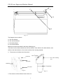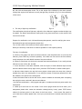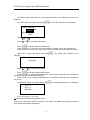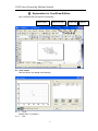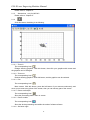
1
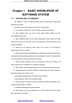
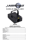
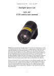
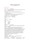
COLE Laser Engraving Machine Manual
My honorable user: we are very appreciative of your choice of using COLE series of product, as well
as your support and trust to the product of the COLE. Cole Company is willing to provide you with
all-inclusive technical support. Methods and techniques for operating the product of the COLE are
available in this user manual for you. In order to better use the equipment, please read the manual
carefully.
ⅠForeword
1. The laser technique introduction
“Jiguang” is translated from the word “laser”. The laser technique is the most important
technological invention in the 20th century, it has a wide and deep influence on human
society. Laser has the character of energy with high density, well in control and untouchable
machining , it has been applied in various industries. From the first laser machine
successfully produced in China in 1961 to now, with the effort of the national laser research,
teaching, producing and using enterprises, the laser technology realm is various, advanced
and applied extensively in our country, it makes great progress in industrialization and
contributes a lot to the technology, the national economy , the foundation of national
defense. It’s an edge science with the integration of light, mechanism and electricity which
combined with laser technique, micro-electronics technique, computer technique,
information technique and machine technique. The laser carving technique is a typical
application which use the laser as the energy, use the computing digital control technique to
control the high accuracy mechanism transmission system and then use the laser to carve
and process. The laser carving technique is widely used in advertisement manufacture, gift
processing and laser marking etc, owing to its feature of high accuracy, high speed and
applicable various materials . It promotes the development of the productivity with the new
and high technique. The widely use in related industry will bring to a new revolution.
the customer is our aim. Wish the new and old customers support us as always and make
efforts for a brighter tomorrow .
1
COLE Laser Engraving Machine Manual
Ⅱ5030 laser carving machine introduction
5030laser carving machine use CO2 laser tube as heat source for carving involving high
technology product of numerical control technique and integrated of light machine and
electricity. adopt CO2 sealed laser tube as the heat sources of the machine , integrate the
most advanced computer digital control technique, it’s a high-tech digital control product
unified optical, mechanism and electricity.
1. Product character:
▲Professional design ideal, customized for the users in different industries , elegant
appearance and practical .
▲Professional moving control design , adopt advanced three-phase stepping motor and
good tansmission system , high speed and precision .
▲Complete function, safe and stable , exclusive no water warning and automatic protection
system , to protect the working life of the laser tube effectively. The power control system
has exclusive automatic protection equipment to ensure the stability and safety of the
machine to the best .
▲ Electronic control lift platform , easy and flexible to operate , can engrave materials with
different heights .
▲ It supports various file formats PLT, BMP (1bit), DXF, AI, etc which created by the
drawing software and can carve various graphs and words.
2. Applicable materials:
Wood ware, paper , leather , cloth, acrylic , epoxy resin,density board, double-colored board,
marble, plastic, rubber, ceramic tile, crystal, onyx, bamboo and other non-metal materials .
3. Applicable industries:
Packing&printing : paper carton, knitting bag, handle bag, rubber board for printing .
Advertisement : acrylic cutting, label making, double-colored board engraving.
Art and craft : wood, bamboo, photo, ornament , prize’s engraving .
Leather&garment: leather, man-made leather, garment embroidery and sampling.
Others : sample, marking, model-making, surface drawing, decoration , etc.
4.
Character of machine :
The laser carving has the characters of high speed , high accuracy and low noise.
In the printing and engraving industry, the accuracy and efficiency are very high.
It can
completely substitute the manual carving, the effect is as good as the flexible board and the
cost is down a lot . The laser carving without surface touching and no need to fix normally.
when cutting acrylic , the cutting edge is smooth and no need to polish, process soft
materials freely .
2
COLE Laser Engraving Machine Manual
5. The main technique parameter index
Model number
5030
Laser power
40W
Laser type
CO2 glass sealed laser tube
Size
Min word model
Chinese characters 3.5mm, English2.5mm
Temperature request *1
5℃~35℃
Cooling temperature*2
5℃~30℃
Relative humidity *3
≤80%
Carve speed
≤50~50000mm/min
Power supply mode
220V/50Hz
Machine power
1000W (without accessory)
Carve platform
The electric control lift platform
Control software
LASERWORLD laser soft V5.0G
Note:
1. Environment temperature: When the environment temperature is above the maximum
temperature, the stability of the equipment will come down because of the poor heat sink.
When the environment temperature is below the minimum temperature, it may cause the
water in the laser machine freeze and the laser tube broken.
2. Cooling water temperature: When cooling water temperature is above the maximum
temperature, the efficiency of laser energy will descend quickly. When cooling temperature
is below the minimum temperature, it may cause the water in the laser machine freeze and
the laser tube broken.
3. Relative humidity: If the relative humidity is too high , it will break the electric circuit and
the high voltage may discharge. It may lead to dangerous and damage to the laser power .
ⅢStructure Introduction of 5030-40
1.The Whole appearance of the equipment
3
COLE Laser Engraving Machine Manual
Fig. 3-1
2. The structure drawing of the equipment
(1)Elevation (the left side diagram)
Top part of the case
Top cover
left or right side small cover
Control panel
Lift platform
right door
Right and left side board
left board
front door
Front side board
base
(2) Back diagram (on the right back side)
4
COLE Laser Engraving Machine Manual
Back cover of top box
Block for laser box
Back cover
Smoke ejected hole
Power socket
Fig. 3-2
3. Structure introduction:
The design of 5030laser carving machine is the newest and perfectly embody in the vision
esthetics , it perfectly unifies the mechanism and optical , and the exclusive design realize
the physical volume of the machine to a minimum.
①Optics part
Optics part is composed of 80W CO2 laser tube, 3 slices of reflector and a slice of focus
mirror. The laser machine emits laser under the high voltage of the laser power ,
transited
by 1,2,3 reflector, and focus into tiny laser beam through focus mirror, and then arrive to the
carving platform. Under the control of numerical control system, it finishes the carving
instruction issued from the computer.
②Machine part
It is made up by the top and bottom machine box, including the base, the front, back, left and
right baffles , control cabinet, machine cover, the laser protection box etc.
③Carving platform
It is made up by the beehive type platform, lift system.(hoist tow motor, transmission belt,
guide rail)
④Transmission system
Including two slippery rails of high accuracy (X-axis、Y-axis), X-axis and Y-axis driving
stepping motor , transmission belt, etc.
⑤Control part
Including the laser power control system, the electrical engine driving controller, output
control card, data bus, the water circulation induction system(or called No Water Warning
5
COLE Laser Engraving Machine Manual
System), control panel ,etc.
ⅣThe Installation of 5030-40
1. Unclose the packing box
5030laser carving machine is designed in detachable structure(See the third chapter in
detail), the product will be packed detachable or integrated before leaving the factory
according to the transportation and customer’s demand. The detachable packing means
pack two parts separately into two wooden boxes, after opening the packing box, the
machine should be assembled and fixed.
Normally detachable structure will be choosed only when the equipment is too large to place
into the customer's operation room, since the detachable type needs complicated
adjustment for the engraving level degree and other precise places.
After opening the packing box ,take out the machine gently , push it to the proper place
(there are versatile wheels in the bottom). If the door is too narrow to get in, it can be apart
and then move into the room.
Be carefully when moving the machine because the laser machine is installed in the
machine.
2. Placement of the machine
(1) After opening the package, place it horizontally, keep certain distance with the wall ,
make it upright and stable .
(2) Place the equipment in the ventilated and dry environment.
3.Install
(1) The preparation of power supply: Prepare for at least two sockets (best with three
sockets including the ground bus). The wire should not be too thin (at least 1.5 mm2 copper
wire). The power is at least 1500W when machine and accessories(wind device and air
pump) working together.
(2) Install the water-cooled system: Prepare a water container above 5L, pour into clean
water. Then open the back baffle of the machine, connect the water output interface of the
pump with the water input interface of the laser machine. Put the pump and water pipe into
the container. Switch on, and wait for the water come out from the pipe , the installation
finishes after the water-circulation is normal . If the machine warns after switch on , or the
water-cooled indicator alarms in red , it indicates the water circulation is abnormal. It also
6
COLE Laser Engraving Machine Manual
can be caused by the wrong connection of the water pipe, the water output interface of the
pump connects to the water output interface of the laser machine. It can not work normally if
the red light warning or the machine alarms.
(3) Connect the main power supply of the machine to the electrical source. Connect the
reverse-interface of the power cord with the socket of automatic control interface of the main
power supply. This interface supplies power to fan and air pump for automatic control.
(4) Connect the smoke-ejected pipe with the wind device and the laser machine. Connect
the air pump wire to the machine wire.
(5) Install the PCI control card: Put the PCI control card into the PCI
slot, fixed by the screw. Connect the data bus to the PCI control
Ground
Wire
card.
Note: Insert and pull out the data bus after power off, or it will
damage the machine or computer mainboard.
(6) Connect the ground wire: the machine can be used normally only
after connecting the ground wire , or it will work abnormality or affect
the working life.
According to the unified standard, the standard build already connect the ground wire. If the
power supply comes from the building’s socket, when the entering line has three holes, that
the top hole of the triangle is the ground wire. (showing as the left diagram). To judge if the
ground wire connect well or not : use the multimeter at the AC250V, measure the two
underneath holes, the multimeter will show the voltage around 220V. Then use the
multimeter pen to measure the voltage between the upper hole and the two underneath
holes, one of it is 220V.That is to say the upper bore is the ground wire, thus there’s no need
to connect the ground wire . Since power cord of the machine is also three pins , ground
wire of the machine can be drew out through the top hole of the triangle. If the user’s power
is only two wires , the user must connect a ground wire to the machine. Normally, the ground
wire connects to the top hole of the triangle (showing as the right diagram) or metal screw of
the machine, another side connects to the water pipe or radiator(since the water pipes all go
into ground). Pay attention to connect well (it’s better to cut the rust from the iron pipe , or a
welding will be more safe) , it’s also acceptable to connect to ground with conductor, if
possible, not less than 50CM depth. These works will not waste too much your time, since
the most important thing is the machine works stably .
To make sure connecting well for each method , The static electricity can be transmitted into
the underground normally. The ground voltage below 5V.
Ⅴ Light Way Structure and the Adjustment Method
1. The diagram of the light way structure
7
Ground
Wire
COLE Laser Engraving Machine Manual
C
A
B
D
Fig. 6-1
The diagram show as above
A- The first reflector
B- The second reflector
C- The third reflector
D- The fourth reflector
Black line and the arrowhead is the laser reflecting way.
The laser from the laser tube beat to the first reflector, then reflect to the third reflector, and
reflect to the third reflector, focus on the surface of the carving material.
2、 The structure of reflector and focus lens
The 3rd reflector
M1 Screw
The laser entering
port
M2 Screw
Reflector
Focus lens
M3 Screw
Fig.6-2
Fig.6-3
3. The structure of the reflector frame: show 6-2
8
COLE Laser Engraving Machine Manual
M1, M2, M3 are hexangular screw. Fix on the angle of the reflector by the three screws.
Change the angle of the reflector to rectify the light way. Showed in Fig. 6-4, the rectification
of the screw.
4. The way of light way rectification
Fig.6-4
The rectification principle of light way: adjust the four reflectors' angles to make the light way
in parallel. The laser head beats the same point in any place and focus on the center of the
focus mirror at last.
Prepare for rectification: tool—M3 small hexangular spanner, used for rectifying the screw.
Dual adhesive tape and transparent plastic slice
Turn off the switch of the machine control system (show 3-3)
Rectify the intensity of the laser as small as possible in control panel (5-6mA)
The way of rectification:
a. Check-up if the laser can emit on the first reflector. (Use the plastic slice to cover the first
reflector, press TEST key to see the position). If the laser can not emit on the first reflector,
rectify the place of the M1,M2,M3 screws of the prior reflector.
b. Check-up if the laser can emit on the second and the third reflectors, if not, rectify the last
reflector’s screw of M1, M2, and M3.
c. At the entrance of the laser drawtube, stick two layers of dual adhesive tape at least,
move the laser head to the top right corner, press the TEST button to create a laser point.
d. Move the laser head to the top left corner project a laser point one more time, observe
whether they are in the same place. If not, rectify the screw of the three reflectors M1, M2,
M3. Make the two points in the same place.
e. Move the laser head to the low left corner, observe whether in the same place comparing
the top right corner, and rectify the second reflector.
f. As above-mentioned d,e , rectify again and again, to make sure the three points emit in the
same place.
h. Check-up if the focus is in the center: Put a mirror upright under the focus mirror, put a
transparent plastic slice under the drawtube closely(hold by hand), press TEST button,
observe if the laser point is in the center of the focus mirror .
focus center. Be careful of
your hand when hold the plastic slice , don’t put your hand into the vertical area of the focus
mirror .
9
COLE Laser Engraving Machine Manual
Note: When rectify the light path , please adjust the M1,M2,M3 screws and angle of the
frame slightly each time , watching the changes of the light path .
Matters needing attention:
1. When rectify the light way, avoid being burned by the laser. Especially rectify in a large
scope, the light way changes a lot, it is easy to hurt people. Stand in the back of the reflector,
and must wear glasses.
2. Make sure the control system is switch off before rectification.
3. Do not pollute the lens when rectify the light way. Use the transparent plastic to confirm
the laser point position, keep plastic slice from the lens above 1mm away. When stick the
dual adhesive tape, prevent it polluting the lens. It is better to change another dual adhesive
tape when the point is too deep.
Ⅵ The Operating Introduction of the Control Panel
1. Main interface of PAD03
10
COLE Laser Engraving Machine Manual
Datum: Laser head will move to the original point of the machine slowly.
Laser: Laser on/off.
Stop: Cease the processing operation.
Test: The laser head will run along the outline border of the processing data.
Start/Pause: Start/pause the processing operation.
Esc: Escape the current status window.
Menu: Enter accessory interface.
: Click this button, then
and
can move the Z axis. This function needs hardware
(machine) support.
: Enter.
Startup interface
When power on, PAD will show” System starting, please wait”.
3
Main interface
The main interface shows as following.
2
FILE
SPEED
POWER
PIECES
AAA
100%
100 / 100%
1
DEL
11
COLE Laser Engraving Machine Manual
File: File names which are saved in MPC6515 controller.
Speed: Percentage of speed. When it is 100, the actual speed is the number which is
set in processing data.
Power: Percentage of power. When it is 100, the actual power is the number which is
set in processing data. There are two options: the former is for “Corner -Power” and the
latter for “Power”.
Pieces: Repeat times of a file.
Del: Delete the current file.
At first, file name is brightened (word is white and background is black).
Now,
Press
and
, and you can select the option you want to modify.
Press
and
, and you can change the number in the selected option.
and all the number will be saved.
Press
Press “Esc” and all the options will not be modified (none of the options is brightened).
Now, press
and you can move the laser head.
Press
4
5
again and you can modify the options (file name is brightened).
Processing interface of PAD03
Press “Start” and the interface will show as following.
FILE
SPEED
POWER
TIME
AAA
100%
100 / 100%
0 :0 :15
File: File name which is being processed.
Speed: Percentage of speed.
Power: Percentage of power.
Time: Time for processing this file.
When processing,
Press
and
for Corner -Power).
Press
and
, and you can change the percentage of power (only for Power, not
, and you can change the percentage of speed.
Press “Start/Pause” and you can control the processing procedure.
Press “Stop” and you can cancel the processing procedure. The interface shows
“Stopped”. Press “Esc” and you can see the main interface.
5
Accessory interface of PAD03
Press “Menu” and you can see the accessory interface.
CUT BDR
LAS
SET
PMOV SET
LANGUAGE
12
COLE Laser Engraving Machine Manual
CUT BDR: Laser head will move a rectangle with laser on according to the size of the
graphics.
LAS SET: Select this option and press
. The LAS SET interface is as following.
LASER TIME SET
000000 MS
POWER SET
100%
Press
Press
or
or
can move the cursor.
can change the number.
and all the number will be saved.
Press
If this number is 0, press “Laser” key and laser on; release “Laser” key and laser off.
If this number is not 0, press “Laser” key, and laser will shoot a certain time as you set.
PMOV SET: Select this option and press
following.
. The PMOV SET interface is as
DISTANCE SET
000.0 MM
Press
or
can change the number.
and all the number will be saved.
Press
If this number is 0, press the direction keys, and the laser head will move; release the
direction keys, and the laser head will stop.
If this number is not 0, press the direction keys, and the laser head will move a distance
as you set.
LANGUAGE: Select this option and press
. The language interface is as following.
简体中文
繁体中文
ENGLISH
Select the language as you prefer.
★Ascending and descending platform button
After turn on the electric source, press the “UP” button the platform ascending, press the
“DN” button the platform descending.
13
COLE Laser Engraving Machine Manual
Suitable for the materials with different thickness by ascending and descending the platform.
The focus distance is the vertical distance from the surface of the material to the focus
mirror in the drawtube. The lift platform need to
adjust when engraving to make sure the focus is
Laserbeam
proper and attain good effect . Focus distance
depends on the focus lens ,the Century Star
product according to different customers, be
Focus mirror
matched with 45, 55, 75mm.The academic focus
is for reference only, in the actual work, you can
Focus distance
choose the smallest and deepest point by
ascending and descending the platform.
Ⅶ Daily Maintenance
Focus diagram
1、Daily operating attention
(1)Be sure the machine works on basis of the water circulation system works normally .
Although the machine has the No Water Warning function, you can’t be careless. Despite
the possibility of the malfunction is low, once the water circulation system unusual and the
warning system fail to work, the laser machine will be broken.
Note: The no-water alarm system is an assistant function offered to the customers. The
inductor is polluted or the voltage fluctuates will bring the malfunction to the alarm system.
So the customer should oftenly check up the alarm system and look-over the water
circulation system in manual. Avoid the laser machine broken because of the malfunction.
Don't depend on the alarm system completely. If you find the alarm system damaged, you
should get in touch with the service department in time. If the customer only depends on the
alarm system, working under the abnormal condition, whether the sensor can provide
normal responding or not , our company will not take the responsibility to the laser machine
damage
(2) Be sure of the machine connection to the ground well, otherwise, it will reduce the
working life of the machine. Check up the connection to the ground frequently . At the same
time the computer should be connected well to the ground also.
(3) Prevent for the laser burning
When the machine is working, please don’t put any part of your body into the laser
transmission path in case of being burned (see light way introduction for details ) . Wear the
protection glasses when you rectify the light way, and adjust the current as little as possible
to avoid the danger .
14
COLE Laser Engraving Machine Manual
(4) When the machine works continuously in long time especially the laser is so strong, the
temperature of the circulating water is very high. It will reduce the laser intensity the working
life of the laser tube. Please replace the water in time and be sure the capacity of water is
enough.
(5) The laser energy depends on the value of the laser current. When the current value
exceed to 15mA, the laser energy will descend. If it lasts for a long time, it will severely
reduce the working life of the laser tube.
(6) The voltage of power supply: The fluctuated voltage will lead to the machine working
unsteady. The high-voltage will damage the equipment of power supply system
permanently . We recommend that the user equipped with a regulator at least 2000W to
protect the machine. Especially for the customer whose voltage is not steady enough .
(7) When thundering or lightning, please do not turn on the machine.
(8) The machine can’t work when the relative humidity over 80%, it will reduce the working
life of the machine or damage the circuit.
(9) When the machine is working, please watch carefully to avoid catching fire , especially
when cutting with high power or engraving the high organic materials . We do not take the
responsibility if the operator without normal training or break the rules of operation.
2. Maintenance
The laser carving machine is a precise equipment, so it is important to maintain the
equipment in order to prolong the using life-span and ensure the process accuracy.
(1) Be sure the stability of the ground wire and connection to the ground well.
(2)Change the circulating water often twice a week to ensure the water is clean. Pour out the
water when the machine stops working for a long time. Keep the water temperature not too
high. (If possible, it’s better to use the pure water )
(3) Be sure that the cool-water can not be frozen under the environment in the lower
temperature to avoid the laser machine being cracked.
(4) Keep the machine clean especially for the optical part and the moving system. The track
and beam should be wiped off often , spread with a thin lubricating oil on it to avoid
rusting.( Please use the absorbent cotton and the engine oil)
(5) The maintenance of the optical equipment
After using for a period, there are many dust on the optical lens (the reflector and the focus
lens). It should be wiped out in time or the laser power , the service life of the lens and
carving effect will be affected. Use the the lens paper or absorbent cotton with alcohol to
clean. Please pay attention and not wipe or touch the lens with rough material.
Cleaning methods for focus mirror: At first, screw the drawtube and get the focus mirror .Be
careful to avoid damage because of its dropping accidentally. Second, blow the surface
floating dust; At last wipe slightly by absorbent cotton dipped into alcohol.
15
COLE Laser Engraving Machine Manual
Note: When you wipe lens, do not wipe at the way of come-and-go,
(seeing the right chart), furthermore, do not use the crude material to
wipe, because a special metal film is plated on the lens surface, if the
film is damaged, it would cause that the laser energy is greatly
attenuated. It is only one time for absorbent cotton to wipe. After that,
notice to inspect so that cotton thread and remnant else cannot be
remained. Do not run machine until volatilization of alcohol is depleted
Ⅸ Familiar Malfunction and the Solution Method
Malfunction
Malfunction Reason
Phenomenon
Solution Method
Electricity failure or connect not
Power on but
no electricity
well
Check the power cord and the power
supply circuits
The fuse melt
Replacement
The pump does not turn on or the
Check the water circulation system
water-cooled circulation system
buzzer alarm
No laser come out
Laser available
only in manual
block
Over-voltage protection
Check the power supply voltage,
laser tube open
replace the laser tube, re-connecting the
or strike fire
positive pole and insulation
Over-voltage
Check the water circulation and the
no-water protection
voltage
The power supply board damage
Replacement
High-voltage bag damage
Replace high-voltage bag
Check whether there is signal in
Yes-The optical coupling of power board
the laser power wire
damage
No-Check the control panel signal
The carving
Check if the wheel of the dolly
shading not
loose or tight
smooth
Catch fire when
carving
Adjust the small wheel
Power board damage
Maintain or replace
The current value too high or the
Adjusting
speed too slow
The air pump not work or connect
The material is not proper for laser
carving
16
Connect the air pump
COLE Laser Engraving Machine Manual
No reaction for
output
Cutting not
complete(cut one
side only)
Cutting depth not
enough
Software, computer system, data
Re-install the system or replace the data
bus install failure
bus
problem in control board
Servicing or replacement
The light way deviation
Rectify the light way
The temperature of laser machine
Replace the circular water
is too high
Platform surface is not smooth
Adjusting
The current value is too low
Strengthen the current
The speed is too fast
Lower the carvings speed
The material is not proper for laser
process
Carving effect not
The light way deviation
Adjusting
The lens is polluted
Clean
The wrong foci\focus lens loosen
Rectify the ascending and descending
good
platform/ tighten focus drawtube
The layout content not good
Rectify the font and image, rectify the
/improper laser current and speed
current value and the carving speed
17
COLE Laser Engraving Machine Manual
Software Part
Ⅰ Installation of the system
1.1 Contents of the system
The system is made up of hardware (control card) and software. Hardware includes a
MPC03-L﹡ or MPC05-L﹡control card. And software includes drivers for the control card
and control software. The whole control system is contained in a packing carton and
software in a CD.
Descriptions on software directories:
subdirectory
Files
Install
Files of installation
Drivers
Drivers of control card
Tools
IOcheck and Vercheck program
Demo Data
PLT, BMP etc. demo data
Read me
Explanations of the software edition
Explanations
1.2 Installation of MPC03 card
1.2.1
Requirement of PC
Requirement of OS: Window2000、Win XP
IBM compatible computer
CPU: Above Pentium 2
Storage: 128 Meg
HD: Above 10 G
CD-ROM
PCI extending slot
Above one USB interface
1.2.2
Auto-installation
To ensure your safety, the following procedure should be abided by:
A、Close PC, and cut off power.
B、Open PC's cover, choose the PCI slot that is not in use and insert control card.
C、Fix control card, and put cover on computer as it is.
D、Connect control card to laser machine by data wire that is attached with machine.
E、Turn on power and run PC.
When PC starts, the control card can be checked automatically. There is an instruction for
finding new hardware. At first, please choose “cancel” and then run the file Drivers\ Win2000
(or Win XP)\ SetupMpc03.exe.
18
COLE Laser Engraving Machine Manual
Click “Setup”, the driver will be installed automatically.
Then restart the computer please.
1.2.3
Manual installation
Generally, the control card can be installed automatically. Sometimes, the control card
can’t be installed because the install program is damaged. Now you have to install the
control card manually.
It is supposed that the OS is installed in C disk.
Copy Mpc03ls.inf in [Drivers] to C:\WINDOWS\INF.
Copy MPC03LS.SYS in [Drivers] to C:\WINDOWS\SYSTEM32\DRIVERS.
1.3 Installation of MPC05 card
Run the file Drivers\ CommCtl.exe.
If this program is not installed, PC can’t communicate with MPC05.
1.4 Installation of the software
Run Setup.exe, the dialog box as following:
19
COLE Laser Engraving Machine Manual
There are three options in “Edition type”, “LaserCut50” should be chose. The default
path is “C:\LaserCut50”. Click
and you can change the install path. Click “Setup” and
the software will be installed.
1.5 Installation of the USB softdog key
There is a USB soft dog key in machine package that should be inserted in any USB slot of
the computer. After this, there is an instruction for finding new hardware. At first, please
choose “cancel”.
Run the file Drivers\ redDogInstdrv.exe.
Please press “Install Driver” button to install the driver of USB soft dog key.
20
COLE Laser Engraving Machine Manual
Ⅱ Explanation for CorelDraw Edition
Run CorelDraw and the interface as following.
Laser output
Import DST file
2.1 Laser output
Click this button, the dialog is as following.
2.1.1
Layer
Please refer to “Chapter 5”
2.1.2
Test
21
Export file
Options
COLE Laser Engraving Machine Manual
Please refer to “Chapter 5”
2.1.3
Stand alone(only for MPC05)
Please refer to “Chapter 5”
2.1.4
Click this button, the dialog is as following.
2.1.4.1 Zoom in
The corresponding icon is
.
Enlarge showing graphics. Click this button, then click your graphics with mouse and
the graphics can be enlarged.
2.1.4.2 Zoom out
.
The corresponding icon is
Reduce showing graphics. Click this button, and the graphics can be reduced.
2.1.4.3 Pan
The corresponding icon is
.
Move screen. Click this button; press the left button of your mouse continuously, and
move your mouse to any place of the screen, then you can see any part of the screen.
2.1.4.4 Room to all object
The corresponding icon is .
Show the processing date in max on screen.
2.1.4.5 Room to table
The corresponding icon is
.
Show the whole processing area within the scale of reference frame.
2.1.4.6 Set laser origin
22
COLE Laser Engraving Machine Manual
The corresponding icon is
Click this button.
.
You can set origin point anywhere as you prefer.
2.1.4.7 Array output options
The corresponding icon is
Click this button.
.
Cell Width(X/Y): It is the original size of the data.
Times: It is the number of rows and columns you need.
Gap: It is the space between two adjacent rows or columns.
Width: It is the width of whole data.
Height: It is the height of whole data.
Gap along Y: It is the space along Y axis between the first and second column.
Gap along X: It is the space along X axis between the first and second row.
Array-data Only Draw Box: If you select this option, there will be only one data on
screen; others will be shown as rectangles.
Auto-cover Calculation: This can calculate the number of row and column that can
cover the whole material according to the parameter you input. Click this button,
23
COLE Laser Engraving Machine Manual
Material width(X): It is the width of the work piece (the default is the worktable’s width).
Material height(Y): It is the height of the work piece (the default is the worktable’s
height).
The following is a sample.
2.1.4.8 Move working table
.
The corresponding icon is
Click this button and move mouse, and you can change the position that the data is in
the working table.
2.1.4.9 Calculate
The corresponding icon is
.
When the graph and processing parameters are changed, this button should be clicked
to save the processing parameters in processing file.
2.1.4.10 Simulate
The corresponding icon is
.
When parameters set is finished, please click this button. It can simulate the procedure
of output for checking the result of output.
2.1.4.11 Set simulate speed
The corresponding icon is
.
Click this button.
24
COLE Laser Engraving Machine Manual
By this tool, you can adjust the simulate speed.
2.1.4.12 Estimate work time
The corresponding icon is
.
Click this button, it will show the work time.
2.1.5
Calculate. When the graph and processing parameters are changed, this button should
be clicked to save the processing parameters in processing file.
2.2 Import DST file
Click this button, you can import DST files.
2.3 Output file
Click this button; you can export the processing files.
2.4 Options
Please refer to “Chapter 6”
Ⅲ Explanation for AutoCAD Edition
Run AutoCAD and the interface as following.
25
COLE Laser Engraving Machine Manual
3.1 Laser output
Please refer to “Chapter 2”
3.2 Export Data
Click this button; you can export the processing files.
3.3 Options
Please refer to “Chapter 6”
3.4 Unite lines
This tool can unite several lines that are intersecting as one line. This is usually used for
DXF files.
Ⅳ Explanation for Universal Edition
When run the software, the interface is as following.
All system function can be found on
tool bars.
Save data
Set array work
Import data
Simulation
Output
Set origin position
Edit tools bar
Layer tools bar
Status bar
Let mouse stay on an icon for a moment, and it will show the explanation of basic function
of tools bar. The following is the explanation of all tool bars.
4.1 File
26
COLE Laser Engraving Machine Manual
4. 1.1
New
The corresponding icon is
.
Create a new file.
4.1.2
Open
The corresponding icon is
.
Load process data made by the software. The file format is ECP-EC Project File
(﹡.ecp).
4.1.3
Save
The corresponding icon is
.
Save the graph data that is defined processing parameters as ECP-EC Project File
(﹡.ecp).
4.1.4
Save As
Save a ECP-EC Project File (﹡.ecp) as another ECP-EC Project File (﹡.ecp).
4.1.5
Import
The corresponding icon is
.
Load data that the software supports. The software can support﹡.PLT、﹡.AI、﹡.DXF、
﹡.DST、﹡.BMP etc files.
4.1.6
Export
Save the vector graph data that is in current window as a standard PLT file (*.PLT) or
DXF file.
4.1.7
Options
Click this button, and the interface is as following.
Any change of these parameters will change the performance of the machine.
Before changing the parameter, you should consult the supplier.
27
COLE Laser Engraving Machine Manual
Details please refer to “Chapter 6”
4.1.8 Exit
Click this button, and the software will close.
4.2 Edit
4.2.1
Undo
The corresponding icon is
4.2.2
.
Redo
The corresponding icon is
4.2.3
Refresh
.
.
The corresponding icon is
Click this button, and you can refresh the screen.
4.2.4
Pick
The corresponding icon is
.
Select graphics. Select graphics or a part of the graphics. You can delete, move,
change layers of the graphics you select.
There are other functions about this button:
Click this button, and select the graphics you prefer.
Move the mouse to the nodes, then drag the mouse, you can change the shape of the
graphics as you prefer.
After you select the graphics, click “Spacebar”.
Input the coordinate of the X-axis and Y-axis, you can change the position of the
graphics.
28
COLE Laser Engraving Machine Manual
4.2.5
Zoom in
.
The corresponding icon is
Enlarge showing graphics. Click this button, then click your graphics with mouse and
the graphics can be enlarged.
4.2.6
Zoom out
.
The corresponding icon is
Reduce showing graphics. Click this button, and the graphics can be reduced.
4.2.7
Pan
The corresponding icon is
.
Move screen. Click this button; press the left button of your mouse continuously, and
move your mouse to any place of the screen, then you can see any part of the screen.
4.2.7
Room to table
The corresponding icon is
.
Show the whole processing area within the scale of reference frame.
4.2.8
Room to all object
The corresponding icon is .
Show the processing date in max on screen.
4.2.9 Center to table
When the data is input, it may be out of the reference frame. Click this button and you
can move data to reference frame. If you select a graph and click this button, the selected
graph will be moved to the center of the reference frame.
4.3 Draw
4.3.1
Line
The corresponding icon is
.
Click this button, move mouse on the screen, and you can draw straight lines freely.
Press “Ctrl” key, and move mouse on the screen, you can draw horizontal lines.
4.3.2
Rectangle
The corresponding icon is
.
Click this button, move mouse on the screen, and you can draw rectangles of various
sizes. Press “Ctrl” key, and move mouse on the screen, you can draw square.
4.3.3
Draw poly-line
The corresponding icon is
.
Click this button, move mouse on the screen, and you can draw poly-line of various
sizes by clicking mouse. If you click “C” key, the line will be closed. Press “Ctrl” key, and
move mouse on the screen, you can only draw beeline.
4.3.4
Ellipse
The corresponding icon is .
Click this button, move mouse on the screen, and you can draw ellipse of various sizes.
29
COLE Laser Engraving Machine Manual
Press “Ctrl” key, and move mouse on the screen, you can draw circle.
4.3.5
Bezier
The corresponding icon is
.
Click this button, move mouse on the screen, and you can draw bezier of various sizes.
4.3.6
Text
The corresponding icon is
.
Click this button, and drag mouse.
If you want to edit the text, please click this button and drag mouse on the text.
Before you change the size of the text, the text should be changed to curve. The “To
curve” button is located in “Tools-- To curve”. When the text changed to curve, the content of
the text can’t be changed.
4.3.7
Copies
The corresponding icon is
Click “select” button
.
, and choose the graphics you want to array copy. Then click
this button.
Input relative parameters, then a number of graphics are copied as “rows X columns”.
Gap means the distance between two adjacent rows or columns.
30
COLE Laser Engraving Machine Manual
4.3.8
Rotate
The corresponding icon is
Click “pick” button
.
, and choose the graphics you want to rotate. Then click this
button, you can rotate the graphics. Click “Spacebar” key after you click
, you will see
following dialog box.
Input the number you want, and you can control the rotate angle.
4.3.9
Mirror (vertically)
The corresponding icon is
Click “pick” button
.
, and choose the graphics you want to edit. Then click this button,
you can change the shape of the graphics. The following is a sample. The upper is original
graphics, and the other is edited.
4.3.10
Mirror (horizontally)
The corresponding icon is
Click “pick” button
.
, and choose the graphics you want to edit. Then click this button,
you can change the shape of the graphics. The following is a sample. The upper is original
graphics, and the other is edited.
31
COLE Laser Engraving Machine Manual
4.3.11
Size
The corresponding icon is
.
Change the size of graphics. Click “pick” button
, then select the graphics you want
to edit. Click this button.
Now, input the number you prefer on X and Y-axis. Click “OK”, the size of graphics can
be changed. If you don’t want to change the proportion of X and Y-axis, you can input one of
the number (X or Y), then click the button
4.3.12
.
Align
.
The corresponding icon is
There are 7 options for aligning.
4.3.13 Edit node
The corresponding icon is
.
Edit the nodes of the selected vector graph. Click this button, the nodes of the selected
graph will show as small squares.
Move mouse to the node, and you can change the shape of the graph by dragging
mouse.
Move mouse to the graph, the mouse will change to a crisscross. Dbclicking mouse will
add a node. Move mouse to the node and click “Delete” key, the node will be deleted.
32
COLE Laser Engraving Machine Manual
4.4 Tools
4.4.1
Data check
Click this button.
This can check if the data is closed, overlap or self-intersect.
When the data is input two times or more, it can’t be processed properly. So if you find
something is unusual such as you can’t engrave a graphics data, please use this tool to
check overlap or others. Click “Check” and it will inform which part of the data is in trouble by
red it. Then click “Delete” key and you can delete unwanted data. Before you click “Delete”
key, you have to click
4.4.2
.
Smooth curve
The corresponding icon is
.
This tool can smooth curves. This can improve the cutting speed. Select the graphics
you want, and click this button.
There are 3 options. Compared with “One Level” and “Two Level”, “Three Level” is
smoother. But the distortion is bigger than the others.
4.4.3
Unite line
This tool can unite several lines that are intersecting as one line. This is usually used for
DXF files.
4.4.4
Offset curve
The corresponding icon is
.
This tool can expand or reduce the data. Select the data you need and click this button.
33
COLE Laser Engraving Machine Manual
Input parameters you need you will get a parallel data and the new data will be set as
another layer. The following is a sample.
4.4.5
To curve
Convert the text to curve.
4.4.6
Output order
By this tool, you can layout the processing sequence as you prefer. Click this button,
Each ID number represents a separate graph. Change the sequence of the ID number,
and the processing sequence will be changed.
4.4.7
Invert colors
The corresponding icon is
.
This is only for BMP. Click “pick” button
, and choose the graphics you want to edit.
Then click this button, the black part will be changed to white and white to black. The
following is the sample.
4.5 Laser
4.5.1
Define cut route
34
COLE Laser Engraving Machine Manual
The corresponding icon is
.
This software will define the starting point and direction automatically. Generally, the
point is on the corner. When you need to change the starting point and direction, you can
click this button, and then move mouse to the starting point (it is a small yellow square). Now
click the left key of mouse, the mouse will be changed to a circle. You can change the
direction by clicking “F” key. If you press the left key of mouse and move mouse, you can
change the starting point. The following is a sample.
4.5.2
Set laser origin
The corresponding icon is
Click this button.
.
You can set origin point anywhere as you prefer.
4.5.3
Array output options
The corresponding icon is
Click this button.
.
35
COLE Laser Engraving Machine Manual
Cell Width(X/Y): It is the original size of the data.
Times: It is the number of rows and columns you need.
Gap: It is the space between two adjacent rows or columns.
Width: It is the width of whole data.
Height: It is the height of whole data.
Gap along Y: It is the space along Y axis between the first and second column.
Gap along X: It is the space along X axis between the first and second row.
Array-data Only Draw Box: If you select this option, there will be only one data on
screen; others will be shown as rectangles.
Auto-cover Calculation: This can calculate the number of row and column that can
cover the whole material according to the parameter you input. Click this button,
Material width(X): It is the width of the work piece (the default is the worktable’s width).
Material height(Y): It is the height of the work piece (the default is the worktable’s
height).
The following is a sample.
4.5.4
Calculate
When the graph and processing parameters are changed, this button should be clicked
to save the processing parameters in processing file.
4.5.5
Clear log
Click this button; the system will clear the log.
4.5.6
Simulate
The corresponding icon is
.
When parameters set is finished, please click this button. It can simulate the procedure
36
COLE Laser Engraving Machine Manual
of output for checking the result of output.
Click “Esc” on the keyboard and you can cancel the simulation process.
4.5.7
Output
.
The corresponding icon is
This is for setting layer parameters, test machine and download data. Details
explanation is in “Chapter 5: laser output”.
4.6 View
4.6.1
Toolbar
File toolbar: Click this button, you can display or hide the following bar.
Output toolbar: Click this button, you can display or hide the following bar.
Edit toolbar: Click this button, you can display or hide the following bar.
Layers toolbar: Click this button, you can display or hide the following bar.
Click “pick” button
and choose a certain part of graphics on screen (after been
chosen, the outline become gray), then click any color button you prefer on the layer bar.
Now a new layer will be added in the layer list automatically.
Align toolbar: Click this button, you can display or hide the following bar.
4.6.2
Status bar
Click this button, you can display or hide the following bar.
The status bar show the coordinates of the position that mouse stay on. It also shows
the name and website of the manufacturer.
4.7 Help
4.7.1
Help
Click this button, and you can see the manual of the software. You can get any
information about how to operate the software.
4.7.2
About
Click this button, and you can see the following dialog box.
37
COLE Laser Engraving Machine Manual
It shows information of the software and our phone number. If you have any question,
don’t hesitate to call us.
4.8 Other button on the tool bar
4.8.1
Set simulate speed
The corresponding icon is
.
Click this button.
By this tool, you can adjust the simulate speed.
4.8.2
Estimate work time
The corresponding icon is
.
Click this button, it will show the work time.
38
COLE Laser Engraving Machine Manual
Ⅴ Laser output
There are 3 parts in this interface as following.
5.1 Layer
Layers management is shown as below:
When there are many layers, the processing sequence is from the top down. Select one
row and click up arrow or down arrow, and the sequence can be changed.
When there are many layers, select one row and click
,and all the processing
parameters of the other layers can be set as the layer that has just been selected.
39
COLE Laser Engraving Machine Manual
5.1.1
Main interface of “Set work mode”
Work Mode: the processing mode of the current layer.
Options: click this button and processing parameters can be set.
Output: the current layer is output or not.
: This is advanced layer options. Click this button.
Output times: processing times for the current layer.
5.1.2 Interface of “set cut options”
Select the mode as Cut; click Options and the dialog box as shown below.
Speed: vector speed on X-Y axis
Power: the laser power when the layer is processed
Corner Power: the laser power when laser head runs on corners
Because when laser head runs on corners, the speed will slow down, if the power is
constant, the corners will be cut deeper than others.
Overlap: When a close graphics can’t be cut as it is (close), adjusting this parameter
can avoid it. This may be caused by mechanical gaps. The best way to avoid this problem is
improve the mechanical precision of the machine.
Not Blow: blowing function is closed.
40
COLE Laser Engraving Machine Manual
Blow with Laser: blowing when laser on. Stop blowing when laser off. This function
needs hardware support.
Always Blow: blowing when laser head moves and stop blowing when processing
procedure finished.
: This is advanced layer options. Click this button.
This is the PWM frequency.
5.1.3 Interface of “set engrave options”
Select the mode as Engrave; click Options and the dialog box as shown below.
Speed: engraving speed on X-axis.
Power: the laser power when a layer is processed.
Scan gap: movement distance on Y-axis when engrave a row on X-axis.
Bi-dir: when engraving, laser emit on both negative X-axis and positive X-axis. When
cancel this function, laser emit on only one direction.
Blow: blow or not. This function needs hardware support.
Expand scale: when engraving small letters, the width of transverse stroke may be
smaller than the actual size. Adjusting this parameter can compensate it.
: This is advanced layer options. Click this button.
Select this option and small circles will fill the graph as following.
41
COLE Laser Engraving Machine Manual
The right “S” is the result of selecting “Fill circle”. You can change the radius and space
by inputting different parameters.
5.1.4
Interface of setting grade engrave optoins
Select the mode as Grade Engrave; click Options and the dialog box as shown below.
Speed: engraving speed on X-axis.
Scan gap: movement distance on Y-axis when engrave a row on X-axis.
Power: the laser power when a layer is processed. This parameter determines the
depth of the slope.
Min-Power: the lowest laser power when grade engraving.
Width: the width of grade.
Bi-dir: when engraving, laser emit on both negative X-axis and positive X-axis. When
cancel this function, laser emit on only one direction.
Blow: blow or not. This function needs hardware support.
Repair: select this option and the engraved letters will be clearer.
Repair per: change the parameter will adjust the definition of the engraved letters.
5.1.5
Interface of setting hole options
Select the mode as Hole; click Options and the dialog box as shown below.
42
COLE Laser Engraving Machine Manual
Power: the laser power when a layer is processed.
Interval: the space between two adjacent holes.
Radiation time: delay time for a hole. It determines the size of holes.
Hole on center: hole on all the center of the close graphs.
Blow: blow or not. This function needs hardware support.
All the defaults are last saved parameters.
5.1.6 Auxiliary processing parameters
In the following dialog box, some auxiliary processing parameters can be set.
Times and Delay: If input 10 in “Times” and 20 in “Delay”, then press ”Run”, you can
get 10 same graphics. And it will stay for 20 seconds after every processing finished. The 20
seconds is for feeding and taking down material. Different time can be set as you need. This
function can increase efficiency a lot.
Immediate: If this option is selected, the software will take the position that the laser
head is as original point. If this option is not selected, the original point will be the position
you set.
: This is advanced layer options. Click this button.
F-length (feeding length): When input a certain number in it, feeding motor will give a
certain space after every processing finished. This function needs hardware support.
F-speed (feeding speed): It set the feeding speed.
5.2 Test
Click Test, and the dialog box as shown below.
43
COLE Laser Engraving Machine Manual
: Move the Y or feeding axis.
: Move the Y or feeding axis.
: Move the X axis.
: Move the X axis.
: Click this button and the laser head will move to the home point of the machine
slowly (the speed is determined by “Slow Speed” that you can change in the “Machine
Parameters Setting” dialog box). Then the laser head will move to the origin point
quickly (the speed is determined by “Fast Speed” that you can change in the “Machine
Parameters Setting” dialog box). This can eliminate the cumulate error. Generally, the
machine should be reset before processing. When run the software, it will be reset
automatically (this function can be cancelled as you prefer).
Length: It determines the distance that the laser head moves.
Power: It determines the intensity of the laser power supply. The minimum value is 0
and the maximum value is 100.
: Laser on.
: Laser off.
: Click this button, and laser head will move as a rectangle without laser emitting
according to the size of the graphics. This function is used for confirming the location of
44
COLE Laser Engraving Machine Manual
work piece.
: Click this button, laser head will move as a rectangle with laser emitting
according to the size of the graphics. This function is also used for confirming the location of
work piece. Click this button, and you can see the following dialog box:
Speed: you can choose different speed according to different material. It’s better to
confirm proper speed through testing.
Power: the laser power when cutting.
Blank: distance between processing graphics and the edge of cutting piece.
Save: save the parameters for next data.
5.3
Stand Alone (Only For MPC05)
5.3.1 Download CFG
Download all the parameters of “Machine Settings” to MPC05 controller. You can also
achieve this by exporting a CFG file (*.mol), and copy this file to MPC05 by USB disk. When
modify the parameters of “Machine Settings” or update the firmware, you have to reset CFG
to configure the machine settings.
5.3.2 Download Current
Download the current processing data to MPC05 controller.
5.3.3 Download file
Download processing data to MPC05 controller.
45
COLE Laser Engraving Machine Manual
5.3.4 Del
Delete the file which is selected.
5.3.5 Del all
Delete all the files in MPC05 controller.
5.3.6 Export Cfg
This will create a *.mol file which includes all the parameters of “Machine Settings”. The
file can be downloaded to MPC05 controller by USB disk.
5.3.7 Export file
This will create a *.mol file which includes all the parameters of a processing data. The
file can be downloaded to MPC05 by USB disk.
Ⅵ Options
Any change of the parameters in “Options” will change the performance of the machine.
Before changing the parameter, you should consult the supplier.
6.1 Main interface
6.2
6.2.1 Information about manufacturer
It shows the basic information about the manufacturer and can’t be modified.
6.2.2 Elapse time
It shows the time that the machine has run. It can’t be modified.
6.2.3 Other options
Use advanced options: There are advanced button as
in “Laser output”. Some
accessorial parameters will help you get better effect. But it will make the software more
46
COLE Laser Engraving Machine Manual
complex. Cancel this option, and you can’t inter the interface of “advanced options”.
With Feed components: This is for feeding axis. If the machine has not feeding axis, this
option should be canceled.
Auto Datum…: If you input a number in it, the machine will datum when the run time
reaches the number. It can eliminate the cumulate error of the mechanism.
6.3 Worktable
6.2.1 Pulse unit
It means the distance that the laser head moves when the control system output a pulse.
If you don’t know this numerical value, please click
.
Move: When the stepping motor moves a circuit, the laser head will move a relative
length. You need to input the number in it.
Need pulse: The number is “driver’s subdivision number” ×200.
6.2.2 Range
It is the available processing area of the machine. If you change the number, the
reference frame of the main interface will be changed accordingly. The moving range of the
1st and the 2nd axis will be restricted by this parameter.
6.2.3 Datum Dir (Datum Direction)
47
COLE Laser Engraving Machine Manual
. It is determined by the position (right or left, up 0r down) of original switch.
6.2.4 Auto datum
If you select this function, when you run the software, it will be reset automatically. The
software can remember the coordinates of laser head. So you can move the laser head very
quickly without worrying that it will overstep the worktable. If this function is canceled, you
can only move the laser head slowly (the speed is “slow speed” and you can change it the
“machine parameter setting” dialog box). And when you move the laser head, you have to
be very careful to avoid striking the machine.
6.2.5 Datum Speed
It determines the speed of datum.
6.2.6 Start Speed
It is the start speed of all axes. Normally, the number should be chosen from 5-30mm/s
according to different machines. If the number set up is too high, machine will shake
intensively.
6.2.7 Const Speed
When cutting, if the (processing) speed is higher than even speed, the laser head will
slow down on corners of the graphics. If the (processing) speed is lower than even speed,
the laser head will not change speed during processing.
6.2.8 Quick Speed
This is the maximum speed of laser head moving without lasers emitting. When move
the laser head up, down, left and right, this parameter will work. If the number is too high,
machine will shake intensively.
6.2.9 Acceleration
It is the acceleration from start speed to quick speed.
6.2.10 Test Speed (fast)
This is the speed that you move the laser head when you select auto datum.
6.2.11 Test Speed (slow)
This is the speed that you move the laser head when you don’t select auto datum.
6.2.12 Laser space
If there are 2 laser heads, the space of the laser heads should be input.
6.4 Feeding
The feeding axis can be used as feeding and lift working table.
48
COLE Laser Engraving Machine Manual
6.3.1 Pulse unit
It means the distance that the laser head moves when the control system output a pulse.
If you don’t know this numerical value, please click
.
Move: When the stepping motor moves a circuit, the laser head will move a relative
length. You need to input the number in it.
Need pulse: The number is “driver’s subdivision number” ×200.
6.3.2 Range
It is the available processing area of the feeding axis. The moving range of the feeding
axis will be restricted by this parameter.
6.3.3 Datum Direction
It is determined by the position (up 0r down) of original switch.
6.3.4 Auto Datum
If you select this function, when you run the software, the feeding axis will be reset
automatically. The software can remember the location of the feeding axis. So you can move
the feeding axis very quickly without worrying that it will overstep the worktable. If this
function is canceled, you can only move the feeding axis slowly (the speed is “slow velocity”
and you can change it the “machine parameter setting” dialog box). And when you move the
feeding axis, you have to be very careful to avoid striking the machine.
6.3.5 Datum Speed
49
COLE Laser Engraving Machine Manual
It determines the speed of datum.
6.3.6 Start Speed
It is the start speed of all axes. Normally, the number should be chosen from 5-30mm/s
according to different machines. If the number set up is too high, machine will shake
intensively.
6.3.7 Acceleration
It is the acceleration from begin speed to fast speed.
6.3.8 Test Speed (fast)
This is the speed that you move the laser head when you select auto datum.
6.3.9 Test Speed (slow)
This is the speed that you move the laser head when you don’t select auto datum.
6.5 Cut
6.4.1 PWM Frequency
It determines the frequency of PWM signal.
6.4.2 Curve Disperse
It determines the precision of graph data. If the number is smaller, the precision will be
higher and cost more time to calculate processing data.
6.4.3 Min close-gas time
When the time between the former blowing off and the next blowing on is less than the
number, the machine will not blow off to protect the blowing switch.
6.4.4 Corner acc
It determines the processing precise when the processing route turns the corner.
When the machine can’t draw lines smoothly, please input a smaller number in
“Acceleration” and “Corner Acc”.
6.4.5 Gap on xy axis
Compensation gap when the motor changes direction. This parameter only works when
cut with even speed.
50
COLE Laser Engraving Machine Manual
6.4.6 Original
The machine draws the graph according the route as it is been made.
6.4.7 Optimize
The software will calculate the route to improve processing efficiency. If you select this
option, there are 2 options.
In-Out: cut from inner to outer.
Down-Up: cut from down to up according the number of “divide-height”.
6.4.8 Automation set cut direction
The software will confirm the direction automatically. If you need to change the direction,
please cancel this function. Compensation
6.4.9 Overlap length
Because of the mechanical gap, circle can’t be cut round. Input a certain number in it,
and you can get the circle more round. But this will increase the processing time.
6.4.10 Circle speed
When cutting small circle (the diameter is especially between 1to 3) with high speed, it
will be distorted. The parameters of “Set circle speed” are used to reduce distortion.
Double-click ether row of the list.
When the radius of circle is in the range between “Min radius” and “Max radius”, the cut
speed will automatically be changed to the number of “Cut speed”.
6.6 Engrave
51
COLE Laser Engraving Machine Manual
6.5.1 PWM Frequency
It determines the frequency of PWM signal.
6.5.2 Engrave options
Double-click ether row of the list.
Begin Speed and End Speed: When the engrave speed is set in the range between
Begin Speed and End Speed, the system will automatically apply the numbers of Acc Length,
Backlash…
Acc length: It is the engraving length without laser emitting. It determines the distance
that the X-axis moves from start speed to (working) speed. If it is not long enough, the
machine will shake intensively.
Backlash: It is used for compensating mechanical gaps. If the engraving edge is not
orderly, please set up number in “Backlash”. This number can be positive or negative.
X start speed: It is the start speed of X-axis when engraving.
X acc: It is the acceleration of X-axis from start speed to (working) speed.
Y speed: It is the speed of Y-axis when engraving.
Y acc: It is the acceleration of Y-axis from start speed to “Y Speed”.
If you find graphics error happens (that is, motor lost step), you can set up a bigger
number in “Accelerator Length” or a smaller number in “Acceleration”.
X offset: when engraving graph is not be the actual position. There is an offset. Input
the offset is OK.
Y offset: when engraving graph is not be the actual position. There is an offset. Input
the offset is OK.
6.7 Grade Engrave
Please refer to 6.5
52
COLE Laser Engraving Machine Manual
6.8 Hole
6.7.1 PWM Frequency
It determines the frequency of PWM signal.
Ⅶ Method to Create Vector Figure File (PLT DXF)
This software support the vector files including : PLT, DXF (R12 )
Vector file can be created by the software such as AutoCAD, CorelDraw ,
Wentai ,etc.
一、Create DXF file in AutoCAD
Current AutoCAD software function is very strong and convenient.
Run the program, draw and layout according to size proportion (1:1 proportion);
the whole figure must be smaller than 650X450mm2, and the coordinate zero
point should be set in the left-bottom corner. Output the file into DXF format
through AutoCAD R12 Version
The methods and skills of using AutoCAD , please consult to AutoCAD service
manual or relative books.
二、Create PLT file in CorelDraw
Run CorelDraw software;
Layout and set the size in CorelDraw;
Choose "file - output" in the menu;
Choose PLT format in “ file type " of the output the communication frame;
Click the output button.
The methods and skills of using CorelDraw , please consult to CorelDraw
service manual or relative books.
三、Create figure file in Wentai software.
Run Wentai painting / engraving software ;
53
COLE Laser Engraving Machine Manual
Make figures or the characters in Wentai software;
Choose PLT format in "file – save in other formats" in the menu;
Choose PLT format in " save type " of the output communication frame;
Click "save " button.
A The methods and skills of using Wentai software, please consult to Wentai
service manual
Ⅷ BMP Location Picture Create Method
The methods to create BMP format in Photoshop:
1.Photoshop
Run Photoshop
2."File - open " open one color picture or scan picture, such as (Fig 7-1 )
(Fig7-1)
3. Choose the size and precision of figure
(1)Click "image-image size”, below window appears:
(图 7-2)
54
COLE Laser Engraving Machine Manual
(2)In “Document Size-Width/Height”, input the actual size of the figure you need .
(Fig.7-3);
(3)in ”image size-Resolution”, input the precision (resolution input 600-1200pixel
/ inch, higher resolution, clearer effect figure you’ll get ).For example : Change
the size of the image into 10CM(width)X12CM(height), the resolution is 1000
pixel / inch (Fig. 7-3);
(4)Click “ok”.
4. Choose: " image -mode-Grayscale ", remove color information.
5. There are two methods to create BMP picture:
Method one:
(1)Choose: “Bitmap” , below window appears :
(图 7-4)
(2)Choose four different types (T) ,(P), (D), (H );
(3)Choose (T) for real core picture to make character or label patterns.
55
COLE Laser Engraving Machine Manual
Choose (P), (D), (H) for wove picture to create different results; normally choose
"(H) halftone screen".
(4)Select "(H) halftone”, then below window appears:
(Fig7-5)
Choose"10~60 line/inch" in “ Frequency (F)” (the precision of wove)
"Angle (N)" selects 45 degrees;
(5)Click the button“OK”
Method Two
(1)Choose: filter- pixelate - colored half , below window appears(Fig.7-6)
(2)Confirming "Max radius", the range of
value is 4~127 pixel , this value decides the
size of color halftone. Computing method:
resolution*0.71/wove precision.
Example: For(Fig. 7-1) =1000 pixel / inch; The
precision of wove needed is 60DPI,
Then , Max radius =1000*0. 7/60 =12
(3)Confirm“Screen Angles (Degrees)” of each
channel .
Input value in “Screen Angles”(the angle of net point and horizontal line),
changing range -360~+360 degree.
Comments:
To the grey level picture, only use channel 1;
To RGB picture, use passage 1, 2 and 3, and corresponding to red ,green and
blue channel respectively.
To CMYK picture, use all the four channels and corresponding cyan, Magenta,
Yellow, Black.
(4)Click the button “ok”;
(5)Choose: The picture - the mode- location picture, choose " 50% valves of
56
COLE Laser Engraving Machine Manual
value " , turn the figure into 1 bitmap mode .
For (Fig.7-7-1) the RGB mode after treating by filter, get (Fig. 7-7-2) the picture
showing as below:
Fig7-7-1
Fig7-7-2
(1)Choose "picture - rotate canvas - horizontal rotate” and rotate the figure.
(2)Save the figure in “BMP” format in “ file-save the copy”.
(3)Finish Graph processing.
The methods and skills of using Photoshop, please consult to Photoshop service
manual and relative books.
●The final explanation right of the manual owns by .
●Our company has the right to modify and change the contents of the manual
without further notice .
●All rights reserved, copy version is prohibitive .
●Specially declare
For any mistakes, please point out.
57