1
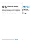
APPLICATION NOTE
AT06412: Real Color ZLL LED Light Bulb with
ATmega256RFR2 – Hardware User Guide
Atmel AVR 8-bit Microcontroller
Description
The reference design of the Real Color ZLL LED Light Bulb is developed to
demonstrate ZLL (ZigBee® Light Link) protocol functions. The reference hardware
includes four parts; AC to DC power supply, Atmel single-chip RF MCU, LED
drive circuit, and LED String board. The LED string is controlled by application
software on Tablet or Smartphone via the ZigBee Light Link protocol commands
through the Atmel® ATmega256RFR2. The Real Color ZLL LED Light Bulb
supports to color switch, tunable brightness, and so on.
For this reference design, the hardware design files (schematic, BOM, and PCB
Gerber) and software source code can be downloaded from the Atmel website.
The provided hardware documentation can be used with no limitations to
manufacture the reference hardware solution for the design.
Features
•
•
•
•
•
•
•
•
Atmel AVR® ATmega256RFR2 microcontroller with 2.4GHz radio transceiver
Drives three parallel high power LED strings (Red, Green, Blue)
Up to 420mA current for each LED string with individual PWM
1kHz PWM input for Dimming Duty Cycle
8W AC to DC power supply
Over–Temperature Detection
E27 Standard Lamp interface
Programming/Debugging interface: JTAG, UART
Figure 1.
Real Color ZLL LED Light Bulb.
42241A−LED−02/2014
Table of Contents
1. Related Items ....................................................................................... 3 2. Overview .............................................................................................. 4 2.2 Components for Setup ...................................................................................... 5 2.1 Preprogramming Firmware ............................................................................... 5 2.2 Power Supply .................................................................................................... 5 2.3 Programming the Kit ......................................................................................... 5 3. Connectors ........................................................................................... 6 3.1 LED Strings Connector ..................................................................................... 6 3.2 AC Source Connector ....................................................................................... 6 3.3 JTAG/UART Header ......................................................................................... 7 3.4 9VDC Power Header......................................................................................... 7 3.5 3.3VDC Power Header ...................................................................................... 7 4. Peripherals ........................................................................................... 9 4.1 AC to DC Switching Power Supply.................................................................... 9 4.2 LED Driver ...................................................................................................... 10 4.2.1 Diode Selection ................................................................................. 10 4.3 ZigBee Transceiver ......................................................................................... 11 4.4 LED String Board ............................................................................................ 11 4.5 LED Indicator .................................................................................................. 12 4.6 Temperature Sensor ....................................................................................... 12 5. Code Examples .................................................................................. 13 AT06412: Real Color ZLL LED Light Bulb with ATmega256RFR2 – Hardware User Guide
[APPLICATION NOTE]
42241A−LED−02/2014
2
1.
Related Items
The following list contains links to the most relevant documents for the ZLL Bulb with Atmel ATmega256RFR2.
•
Atmel MCU Wireless Atmega256RFR2/ Atmega128RFR2/ Atmega64RFR2 Summary Datasheet
The document contains complete and detailed description of all modules included in the Atmel MCU wireless
microcontroller family.
•
Atmel MCU Wireless Atmega256RFR2/ Atmega128RFR2/ Atmega64RFR2 Datasheet
ATmega256RFR2 is the microcontroller used in this solution.
•
RCB256RFR2 – Hardware User Manual
The document describes the usage, design, and layout of the Atmel ATmega256RFR2 radio controller board.
•
Atmel Studio 6
Atmel Studio 6 is a free Atmel IDE for development of C/C++ and assembler code for Atmel microcontrollers.
•
Atmel JTAGICE3
JTAGICE3 is a mid-range development tool for Atmel AVR 8- and 32-bit microcontrollers with on-chip
debugging for source level symbolic debugging, Nano Trace (if supported by the device) and device
programming.
AT06412: Real Color ZLL LED Light Bulb with ATmega256RFR2 – Hardware User Guide
[APPLICATION NOTE]
42241A−LED−02/2014
3
2.
Overview
The Atmel AVR Real Color ZLL LED Light Bulb kit is intended to demonstrate the Atmel AVR Atmega256RFR2
single-chip microcontroller and radio transceiver which is used in the Bulb application via ZigBee Light Link protocol.
The kit includes three circuit boards: Power Supply Board, MCU Control Board, and LED String Board.
Power Supply Board contains the AC to DC switching power supply and the DC to DC circuit. It supplies power for
the whole system. The board provides 9.3V and up to 850mA.
MCU Control Board contains the MCU ATmega256RFR2, antenna, and the LED driver controller.
LED String Board is configured as three parallel LED strings: two Green LEDs, two Red LEDs and one Blue LED.
Figure 2-1 shows the available features on the board.
Figure 2-1. Overview of Real Color ZLL LED Light Bulb
AT06412: Real Color ZLL LED Light Bulb with ATmega256RFR2 – Hardware User Guide
[APPLICATION NOTE]
42241A−LED−02/2014
4
2.2
Components for Setup
The components listed in Table 2-1 are necessary to perform all functions of the reference design.
Table 2-1.
2.1
Components for Kit Setup
Component
Function
Lamp with E27 Reference hardware Kit
ZLL Bulb assembled with Power Supply Board, MCU Control
Board, and LED String Board
Lamp Holder with E27
Supply 110V/220VAC and 50/60Hz frequency Power to the kit
Programming Tool with JTAG interface
Debug and Programming
ZLL/Ethernet Gateway
Communicate between the kit and Wi-Fi Router
Wi-Fi Router
Communicate between the Tablet or Smartphone and
ZLL/Ethernet Gateway
Tablet or Smartphone based on the Android
System
Control the kit using application software
Application Software
Running on the Tablet or Smartphone to control the Kit
Preprogramming Firmware
The Atmel ATmega256RFR2 on the kit is programmed with the default firmware. The detailed description of the
firmware is available in the AT06482 Real Color ZLL LED Light Bulb with ATmega256RFR2 – Software User Guide.
2.2
Power Supply
The kit is powered from an AC line in the voltage range 85VAC and 264VA with 50/60Hz frequency. The AC to DC
switching power supply can deliver 9.3V and up to 850mA.
The 9.3V is converted to proper voltage and supply to LED string. It is also regulated down to 3.3V by an onboard
DC-DC regulator, which provides power to the entire main board.
2.3
Programming the Kit
The kit can be programmed from an external programming tool through the JTAG interface.
AT06412: Real Color ZLL LED Light Bulb with ATmega256RFR2 – Hardware User Guide
[APPLICATION NOTE]
42241A−LED−02/2014
5
3.
Connectors
The Real Color ZLL LED Light Bulb kit has several connectors and headers dedicated for difference purposes. They
are shown in Table 3-1.
Table 3-1.
3.1
Connector and Functions
Connector
Function
J1
Green LED String connector
J2
Blue LED String connector
J3
Red LED String connector
J4
AC source connector
J5
JTAG/UART interface for programming and debug
J6,J8
9VDC power header
J7,J9
3.3VDC power header
LED Strings Connector
The J1, J2, J3 are the LED Strings connector. It provides a connection from the MCU Control Board to the LED
String Board. The header is polarity sensitive.
Table 3-2.
Pin on Green LED String Connector
Name on the LED Connector
1
G+
2
G-
Table 3-3.
Blue LED String Connector J2
Pin on Blue LED String Connector
Name on the LED Connector
1
B+
2
B-
Table 3-4.
3.2
Green LED String Connector J1
Red LED String Connector J3
Pin on Blue LED String Connector
Name on the LED Connector
1
R+
2
R-
AC Source Connector
The AC Source Connector J4 connects to AC line which is a high voltage.
Pay attention; DO NOT touch them for your safety when running the kit.
Table 3-5.
AC Source Connector J4
Pin on AC Source Connector
Name on the AC Source Connector
1
L (LIVE WIRE)
2
N (NEUTRAL WIRE)
AT06412: Real Color ZLL LED Light Bulb with ATmega256RFR2 – Hardware User Guide
[APPLICATION NOTE]
42241A−LED−02/2014
6
3.3
JTAG/UART Header
The Atmel AVR ATmega256RFR2 can be programmed and debugged via JTAG header. Any tools which carry the
JTAG interface can program and debug the kit. JTAGICE3 is recommended for programming. The definition of the
JTAG interface can be found in Table 3-6.
Table 3-6.
AVR ATmega256RFR2 Programming and Debugging Interface -JTAG
Pin on programming header
Pin on AVR ATmega256RFR2
JTAG
1
PF4
TCK
2
-
GND
3
PF6
TDO
4
-
VCC
5
PF5
TMS
6
RSTN
nSRST
7
-
-
8
-
-
9
PF7
TDI
10
-
GND
The definition of the UART interface can be found in Table 3-7.
Table 3-7.
AVR ATmega256RFR2 Universal Asynchronous Receiver/Transmitter Interface - UART
Pin on programming header
Pin on AVR ATmega256RFR2
UART
1
-
-
2
-
GND
3
-
-
4
-
VCC
5
-
-
6
-
-
7
PE0
RXD
8
PE1
TXD
9
-
-
10
-
-
The JTAG and UART interface uses the different pins at the same header.
3.4
9VDC Power Header
The connectors J6 and J8 provide a connection of the 9VDC from the Power Supply Board to the MCU Control
Board. The header is polarity sensitive.
Table 3-8.
3.5
9VDC Power Header
Pin on 9VDC power header
Name on the 9VDC power header
1
9V+
2
GND
3.3VDC Power Header
The connectors J7 and J9 provide a connection of the 3.3VDC from the Power Supply Board to the MCU Control
Board. The header is polarity sensitive.
AT06412: Real Color ZLL LED Light Bulb with ATmega256RFR2 – Hardware User Guide
[APPLICATION NOTE]
42241A−LED−02/2014
7
Table 3-9.
3.3VDC Power Header
Pin on 3.3VDC power header
Name on the 3.3VDC power header
1
3.3V+
2
GND
AT06412: Real Color ZLL LED Light Bulb with ATmega256RFR2 – Hardware User Guide
[APPLICATION NOTE]
42241A−LED−02/2014
8
4.
Peripherals
Figure 4-1 shows the Real Color ZLL LED Light Bulb system block diagram.
Figure 4-1. Real Color ZLL LED Light Bulb System Block Diagram
L
85~264VAC
50/60Hz
AC‐DC Power Supply
9VDC
N
R
DC‐DC G
B
3.3VDC
RF Antenna
PWM1#
MCU
ATmega256
RFR2
PWM2#
PWM3#
Warning:
LED Driver LED Driver LED Driver The kit has high voltages on the board that pose a shock hazard to the user. Appropriate care
should be taken when operating the board. In addition to the high power LEDs are used on the
LED String board. Do not look directly at the LEDs when the board is active and/or protect your
eyes with dark glasses since the LEDs are very bright.
To turn on the board, simply plug the power cord into an 85V to 264V and 50/60Hz frequency power source. The
LEDs light at application of power.
4.1
AC to DC Switching Power Supply
The AC to DC switching power supply, the iw1706, is used to PWM controller. The power supply uses a primaryside control technology to eliminate the opto-isolated feedback and secondary regulation circuits required in
traditional designs.
The AC to DC power supply works at the fixed-frequency Discontinuous Conduction Mode (DCM) operation at
higher output load, and switches to variable frequency operation at light output load for obtaining maximum
efficiency. In other words, it uses adaptive multi-mode PWM/PFM control to dynamically change the BJT switching
frequency for efficiency and EMI.
The AC to DC power supply build-in fault protection features include overvoltage protection (OVP), output short
circuit protection (SCP), and over current protection (OCP).
The AC to DC power supply provides 9.3V and up to 850mA for system, and input voltage range is 85V to 264VAC
with 50/60Hz frequency.
AT06412: Real Color ZLL LED Light Bulb with ATmega256RFR2 – Hardware User Guide
[APPLICATION NOTE]
42241A−LED−02/2014
9
4.2
LED Driver
The PT4115 device is used as LED driver. It is a continuous conduction mode inductive step-down converter,
designed for driving single or multiple series connected LED from a voltage source. The device operates from an
input power supply between 8V to 30V, and provides an externally adjustable output current of up to 1.2A via set by
the sample resistance Rs. The device includes the power switch, and accepts either a DC voltage or a PWM
dimming. In this reference design, the PWM dimming method is used. In order to avoid the flicker of the LED, the
PWM frequency set to 1kHz in the design.
Note: It is better that the voltage difference between the input supply and the LED string more than 2V.
Figure 4-2 shows the typical application circuit of the PT4115.
Figure 4-2. Typical Application Circuit of the PT4115
Table 4-1.
4.2.1
PWM Dimming of the LED Strings
Pin on AVR ATmega256RFR2
Function
PE3
Dimming Red String LED
PE4
Dimming Blue String LED
PE5
Dimming Green String LED
Diode Selection
For maximum efficiency and performance, the rectifier D should be a fast low capacitance Schottky diode with low
reverse leakage at the maximum operating voltage and temperature. It is important to select parts with a peak
current rating above the peak coil current and a continuous current rating higher than the maximum output load
current. It is very important to consider the reverse leakage of the diode when operating above 85°C. Excess
leakage will increase the power dissipation in the device and if close to the load may create a thermal runaway
condition.
AT06412: Real Color ZLL LED Light Bulb with ATmega256RFR2 – Hardware User Guide
[APPLICATION NOTE]
42241A−LED−02/2014
10
4.3
ZigBee Transceiver
The Atmel AVR ATmega256RFR2 device integrated a high performance RF-CMOS 2.4GHz radio transceiver.
In the design, only four components, ATmega256RFR2, Balun, Capacitance and Antenna, consist of RF function
circuit.
Figure 4-3. RF Function Circuit
In order to obtain high performance about the RF, the PCB layout is very important.
How to design the PCB about the RF circuit; refer to the application note Atmel AVR10004: RCB256RFR2 –
Hardware User Manual.
4.4
LED String Board
Pay attention; DO NOT look at the LEDs directly when they are lit. Otherwise LEDs may potentially harm the
user’s eyes.
In order to get the perfect feeling of mixed color, two Green LEDs, two Red LEDs and one Blue LED are used in the
design, and the LEDs should be well positioned in PCB layout.
Figure 4-4. Placement of the LEDs
AT06412: Real Color ZLL LED Light Bulb with ATmega256RFR2 – Hardware User Guide
[APPLICATION NOTE]
42241A−LED−02/2014
11
4.5
LED Indicator
There is a LED available on the board that can be used to indicate the working condition of the kit. The green LED
can be activated by driving the connected I/O line to VCC.
Table 4-2.
4.6
LED Connections
Pin on AVR ATmega256RFR2
LED
PE2
Green LED
Temperature Sensor
The design is equipped with one temperature sensor (100kΩ NTC) connected to the ADC channel of the MCU. The
power is supplied by 3.3VDC. The ADC reference is internal 1.6V reference voltage to reduce the error caused by
external power.
Table 4-3.
Temperature Sensor Connection
Pin on AVR ATmega256RFR2
Temperature Sensor
PF1
NTC
AT06412: Real Color ZLL LED Light Bulb with ATmega256RFR2 – Hardware User Guide
[APPLICATION NOTE]
42241A−LED−02/2014
12
5.
Code Examples
The example application is based on the Atmel Software Framework that is included in Atmel Studio 6. The Atmel
Software Framework can also be found as a separate package online at:
http://www.atmel.com/tools/avrsoftwareframework.aspx.
For more information about the code example, see the application note AT06482: Real Color ZLL LED Light Bulb
Reference Design with ATmega256RFR2 – Software User’s Guide.
AT06412: Real Color ZLL LED Light Bulb with ATmega256RFR2 – Hardware User Guide
[APPLICATION NOTE]
42241A−LED−02/2014
13
Revision History
Doc. Rev.
Date
Comments
42241A
02/2014
Initial document revision
AT06412: Real Color ZLL LED Light Bulb with ATmega256RFR2 – Hardware User Guide
[APPLICATION NOTE]
42241A−LED−02/2014
14
Atmel Corporation
Atmel Asia Limited
Atmel Munich GmbH
Atmel Japan G.K.
1600 Technology Drive
Unit 01-5 & 16, 19F
Business Campus
16F Shin-Osaki Kangyo Building
San Jose, CA 95110
BEA Tower, Millennium City 5
Parkring 4
1-6-4 Osaki
USA
418 Kwun Tong Road
D-85748 Garching b. Munich
Shinagawa-ku, Tokyo 141-0032
Tel: (+1)(408) 441-0311
Kwun Tong, Kowloon
GERMANY
JAPAN
Fax: (+1)(408) 487-2600
HONG KONG
Tel: (+49) 89-31970-0
Tel: (+81)(3) 6417-0300
www.atmel.com
Tel: (+852) 2245-6100
Fax: (+49) 89-3194621
Fax: (+81)(3) 6417-0370
Fax: (+852) 2722-1369
© 2014 Atmel Corporation. All rights reserved. / Rev.: 42241A−LED−02/2014
Atmel®, Atmel logo and combinations thereof, Enabling Unlimited Possibilities®, AVR®, and others are registered trademarks or trademarks of Atmel Corporation
or its subsidiaries. Other terms and product names may be trademarks of others.
Disclaimer: The information in this document is provided in connection with Atmel products. No license, express or implied, by estoppel or otherwise, to any intellectual property right is granted by this
document or in connection with the sale of Atmel products. EXCEPT AS SET FORTH IN THE ATMEL TERMS AND CONDITIONS OF SALES LOCATED ON THE ATMEL WEBSITE, ATMEL ASSUMES
NO LIABILITY WHATSOEVER AND DISCLAIMS ANY EXPRESS, IMPLIED OR STATUTORY WARRANTY RELATING TO ITS PRODUCTS INCLUDING, BUT NOT LIMITED TO, THE IMPLIED
WARRANTY OF MERCHANTABILITY, FITNESS FOR A PARTICULAR PURPOSE, OR NON-INFRINGEMENT. IN NO EVENT SHALL ATMEL BE LIABLE FOR ANY DIRECT, INDIRECT,
CONSEQUENTIAL, PUNITIVE, SPECIAL OR INCIDENTAL DAMAGES (INCLUDING, WITHOUT LIMITATION, DAMAGES FOR LOSS AND PROFITS, BUSINESS INTERRUPTION, OR LOSS OF
INFORMATION) ARISING OUT OF THE USE OR INABILITY TO USE THIS DOCUMENT, EVEN IF ATMEL HAS BEEN ADVISED OF THE POSSIBILITY OF SUCH DAMAGES. Atmel makes no
representations or warranties with respect to the accuracy or completeness of the contents of this document and reserves the right to make changes to specifications and products descriptions at any time
without notice. Atmel does not make any commitment to update the information contained herein. Unless specifically provided otherwise, Atmel products are not suitable for, and shall not be used in,
automotive applications. Atmel products are not intended, authorized, or warranted for use as components in applications intended to support or sustain life.