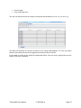
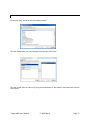
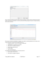
1
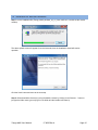
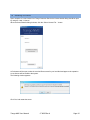
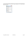
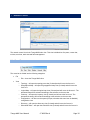
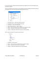
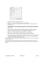
 Trango NMS Wireless Network Management System (NMS) Installation and User Manual Trango NMS User Manual LT‐9066 Rev A Notice This document contains information that is confidential and proprietary to Trango Systems, Inc. No part of the content of this publication may be reproduced, modified, used, copied, disclosed, conveyed, or distributed to any party in any manner whatsoever without prior written authorization from Trango Systems, Inc. This document is provided as is, without warranty of any kind. Trademarks Trango Systems®, StrataLink®, and TrangoLINK Giga® are registered trademarks of Trango Systems, Inc. Other names mentioned in this publication are owned by their respective holders. Statement of Conditions The information contained in this document is subject to change without notice. Trango Systems, Inc. shall not be liable for errors contained herein or for incidental or consequential damage in connection with the furnishing, performance, or use of this document, software or equipment supplied with it. Information to User Any changes or modifications of equipment not expressly approved by the manufacturer could void the user’s authority to operate the equipment and the warranty for such equipment. Trango Systems, Inc. 14118 Stowe Drive, Suite B Poway, CA 92064 Tel.: +1 (858) 391‐0010 Fax: +1 (858) 391‐0020 Copyright © 2014 by Trango Systems, Inc. All rights reserved. Trango NMS User Manual LT‐9066 Rev A
Page 2
Revision History Revision
1.0
Revision Date
5 Dec 2014
Trango NMS User Manual Description
Initial Release
LT‐9066 Rev A
Page 3
Table of Contents
1 Overview ............................................................................................................................... 6 2 Installation ............................................................................................................................ 7 2.1 Pre Requirements ..................................................................................................................... 7 2.1.1 Server............................................................................................................................. 7 2.1.2 Client.............................................................................................................................. 9 2.2 Installation on Microsoft Windows ............................................................................................ 10 2.3 Installation on Linux................................................................................................................ 15 3 First Time Operation .......................................................................................................... 16 3.1 Server.................................................................................................................................... 16 3.2 Client ..................................................................................................................................... 16 3.3 Getting a License .................................................................................................................... 17 3.4 Installing a License ................................................................................................................. 18 4 Login ................................................................................................................................... 19 5 Administration.................................................................................................................... 21 5.1 Access Control ........................................................................................................................ 21 5.1.1 Users............................................................................................................................ 21 5.1.2 Profiles ......................................................................................................................... 22 5.1.3 Views ........................................................................................................................... 25 5.1.4 Password ...................................................................................................................... 26 5.1.5 Connected Users............................................................................................................ 26 5.2 Audit Trail .............................................................................................................................. 27 5.3 Northbound Interface .............................................................................................................. 28 5.4 Email ..................................................................................................................................... 29 5.5 Fault Management .................................................................................................................. 31 5.5.1 Events Configuration ...................................................................................................... 31 5.5.2 Trap Receive ................................................................................................................. 32 5.6 Server Settings ....................................................................................................................... 33 5.6.1 File Transfer Setting....................................................................................................... 33 5.6.2 Syslog Server ................................................................................................................ 33 5.7 Database Settings ................................................................................................................... 35 5.8 Options .................................................................................................................................. 36 5.9 License Manager ..................................................................................................................... 37 5.10 About dialog ........................................................................................................................... 38 Trango NMS User Manual LT‐9066 Rev A
Page 4
6 Network Control ................................................................................................................. 39 6.1 Menu Bar ............................................................................................................................... 39 6.2 Tool Bar ................................................................................................................................. 40 6.3 Tree View............................................................................................................................... 41 6.4 Work Area .............................................................................................................................. 47 6.5 Fault Management .................................................................................................................. 48 6.6 Geographical Map ................................................................................................................... 48 6.7 Logical Map ............................................................................................................................ 50 6.8 Inventory ............................................................................................................................... 52 6.9 Configuration.......................................................................................................................... 53 6.10 Discovery ............................................................................................................................... 54 6.11 Scheduled Tasks ..................................................................................................................... 57 6.11.1 Database Backup ........................................................................................................... 58 6.12 ICMP Ping .............................................................................................................................. 59 6.13 SNMP Ping.............................................................................................................................. 60 6.14 Traceroute ............................................................................................................................. 61 6.15 Open SSH .............................................................................................................................. 61 6.16 Open Web UI ......................................................................................................................... 61 6.17 Not Manage............................................................................................................................ 62 6.18 Collect PM .............................................................................................................................. 62 7 Fault Management ............................................................................................................. 63 7.1 Event Log............................................................................................................................... 63 7.2 Open Alarms........................................................................................................................... 66 8 Dashboard .......................................................................................................................... 67 8.1 Toolbar .................................................................................................................................. 67 8.2 Views..................................................................................................................................... 68 8.2.1 History View.................................................................................................................. 68 8.2.2 Current View ................................................................................................................. 71 9 Appendix A: Installing PostgreSQL ................................................................................. 74 10 Appendix B: Creating a PostgreSQL DB ......................................................................... 79 Trango NMS User Manual LT‐9066 Rev A
Page 5
1
Overview
Trango NMS is a network management system developed specifically for Trango Systems Wireless
Radios. Trango NMS is used for configuration, monitoring and maintenance of Trango's all-outdoor, split
and indoor systems. Trango NMS functionality includes:
1. Automatic Discovery of Trango devices
2. Monitoring of Trango devices
3. Configuration of Trango devices
4. Fault Management (Traps, Alarms and Event Log)
5. Performance Monitoring (Real Time and History statistics)
6. Scheduled Bulk Operations (Software Upgrade, Configuration Backup)
7. Security Management (Users, Roles and View)
8. Licensing (Limiting use by number of device, time and features)
Trango NMS is separated into two applications, server and client.
The server application is a background service installed on the server machine which is responsible for all
tasks that does not require user interface.
The client application is a frontend UI which lets the user monitor and configure managed devices. The
client application can be installed on the user PC or can be downloaded directly from the server by using
the Java Applet technology.
Both server and client are developed in Java programming language and are platform independent.
Trango NMS is delivered as a single executable file for each OS Windows and Linux.
Trango NMS supports Windows 64/32 bit systems and Linux 64bit systems. The executable will take care
of:
1. Uninstalling of previous versions in case of upgrade
2. Starting and stopping background services
3. Unpacking files into selected directory
4. Integrating Trango NMS into the OS menus and screens
Trango NMS User Manual LT‐9066 Rev A
Page 6
2
Installation
2.1
Pre Requirements
Note: Before installing Trango NMS client and server application you need to install PostgreSQL and DB.
See the appendixes at the end of this document.
2.1.1 Server
Installation of the Trango NMS server requires a dedicated server machine meeting the following
hardware, Operating System and network requirements:
2.1.1.1 Server Hardware Requirements:
Network
Elements
CPU
Memory
Disk
Recommended Model
Type
<2,000
Intel® Xeon® E31220
4GB
500GB
Dell PowerEdge R210II
<10,000
Intel® Xeon® E52430 processor
8GB
500GB
PowerEdge R420 rack
server
<50,000
2x Intel® Xeon®
E7540 2.00GHz
32GB
1TB
PowerEdge R910 rack
server
<100,000
2x Intel® Xeon®
X7560 2.26GHz
64GB
2TB
PowerEdge R910 rack
server
• Display: 1024 * 768, 32 bit color
• Misc.: Keyboard, Mouse, 1Gbit Network Interface Card (NIC)
2.1.1.2 Server Minimum Software Requirements:
• Operating System:
o
Microsoft Windows Server 2003/2008/2012
o
Enterprise RedHat Linux Server 5
o
CentOS 5 Server
o
Ubuntu Server 12.04
Network Requirements:
Trango NMS User Manual LT‐9066 Rev A
Page 7
• The following ports should be left free (not used by any other application):
o
TCP port #443 – Used by the web server for accepting client connections.
o
UDP port #161 - Used by the internal SNMP agent for Northbound Interface access.
o
UDP port #162 – For trap reception from network elements.
• If clients should be connected from a remote site, the TCP port #443 should be exposed in the firewall
(if exist) for client/server communication.
• If devices are managed on remote sites, UDP port #162 should be exposed in the firewall (if exist) for
trap reception.
Upon Syslog server is activated, UDP and/or TCP port #514 is required.
Trango NMS User Manual LT‐9066 Rev A
Page 8
2.1.2 Client
The Trango NMS client can be installed on a PC or it can be run as a web application (Java Applet) by
using the client PC internet browser.
Below are the client hardware and software requirements based on the number of elements managed:
2.1.2.1 Client Hardware Requirements:
Network Elements
CPU
Memory
Disk
<25,000
Intel® Core™ i3-3120M
2GB
10GB
<50,000
Intel® i5-3230M
4GB
50GB
<100,000
Intel® i7-3770
8GB
50GB
• Display: 1024 * 768, 32 bit color
• Misc.: Keyboard, Mouse, 100Mb Network Interface Card (NIC)
2.1.2.2 Client Minimum Software Requirements:
• Operating System:
o
Microsoft Windows XP /7
o
RedHat Linux Desktop 5
o
CentOS Desktop 5
o
Ubuntu 11
When running the client as a web application, the hardware and Operating System requirements are the
same as above with the additional requirement for the installation of one of the following web browsers:
• Internet Explorer 9
• Firefox 20
• Chrome 27
Trango NMS User Manual LT‐9066 Rev A
Page 9
2.2
Installation on Microsoft Windows
Step 1: run the installation file (Trango_NMS_windows_a_b_c_d.exe, while a, b, c and d are the version
number).
The above splash screen will appear for several seconds, then the installation wizard will start its
operation.
Click the ‘Next’ button and move to the next step.
Step 2: Select destination directory by using the default, browse by clicking on the ‘Browse…’ button or
just type the folder name (you may type a new folder and the installer will create it).
Trango NMS User Manual LT‐9066 Rev A
Page 10
Click the ‘Next’ button to move to the next step.
Step 3: Select the components you want to install, you may install the client only or to install both the
server and client.
Click the ‘Next’ button to move to the next step.
Step 4: Set the start menu group name by using the default, select from the existing groups list or just
type the group name (you may type a new group name and the installer will create it).
Trango NMS User Manual LT‐9066 Rev A
Page 11
Click the ‘Next’ button to move to the next step.
Step 5: Create or do not create a desktop icon for running the client application.
Click the ‘Next’ button to move to the next step.
Step 6: Now the installer will copy relevant files and install them on the machine. This step might take a
couple of minutes.
Trango NMS User Manual LT‐9066 Rev A
Page 12
Click the ‘Next’ button to move to the next step.
Step 7: Select the relevant network. (You can select the 'Keep current settings' for next installations).
Click the ‘Next’ button to move to the next step.
Step 8: Installation is now completed. Click the ‘Finish’ button to close the installer.
Trango NMS User Manual LT‐9066 Rev A
Page 13
Note: Once the installation process finished both following services should be started
The PostgreSQL service:
The Trango NMS Server service:
Trango NMS User Manual LT‐9066 Rev A
Page 14
2.3
Installation on Linux
The Linux installation of Trango NMS server does not include database installation which must be
installed before Trango NMS installation (please refer to the Linux server documentation for assistance).
Other than the DB, the installation process is exact the same as for the Microsoft Windows operating
system, please refer to section 1.2 in this document for step-by-step guidance.
The Linux server may require additional administration settings for security purposes. The following is a
short description of the commonly required settings:
Since the NMS is installed under the /opt/ directory or under /usr/ directory (OS depended) and since the
NMS require port numbers that less than 1024, the installer needs to be run by root user.
1. Before running the installer change to root user or run commands with sudo
2. Change the installer file permission add execute permission
chmod +x <installer_file_name>
3. Run the installer as root user
Starting and stopping the service under linux
1. Change to root user
2. Run: /sbin/service <server_executable> start -> to start the service
3. Run: /sbin/service <server_executable> stop -> to start the service
4. Run: /sbin/service <server_executable> status -> to see the service status
Trango NMS User Manual LT‐9066 Rev A
Page 15
3
3.1
First Time Operation
Server
After software installation is complete, the server machine should be rebooted. The server is
automatically launched upon reboot. The server has no user interface and its configuration is done by the
client (by allowed users).
3.2
Client
The client may be run as an installed application or as a web application after the server software is
running.
Running the client installed application is done by double-clicking on the desktop icon (if created during
the installation process) or by using the programs menu item (as configured during the installation
process).
Running the web client application is done by opening a web browser and typing the Trango NMS server
IP URL: https://ip_address.
After running the client, in either option, a login dialog will be shown.
Default username is ‘admin’ and the default password is ‘admin’. After typing username and password,
click the ‘Login’ button.
Trango NMS User Manual LT‐9066 Rev A
Page 16
3.3
Getting a License
Upon first time operation or upon new license requirement due to requiring a new license for
management of more devices or additional management features the ‘License Details’ dialog should be
used.
The ‘License Details’ dialog is opened by using the ‘Help’->’License’ menu item.
A new registration key is retrieved by clicking the ‘Copy Registration Key to Clipboard’ and pasting the
key information to an email to be sent to Trango Customer Service. Trango Customer Service will create
and send the license file back via email.
Trango NMS User Manual LT‐9066 Rev A
Page 17
3.4
Installing a License
Upon reception of a new license from Trango Customer Service the license details dialog should be open
by using the ‘Help’->’License’
When the license details dialog is shown, click the ‘Select License File…’ button.
A file browser will be open, select the received file as stored in your local disk and approve the operation.
A new license will be loaded to the system.
The following window appears:
Click 'Yes' and restart the server.
Trango NMS User Manual LT‐9066 Rev A
Page 18
4
Login
Upon running the client application or the client web application, the login dialog is shown.
Typing the username and the password and clicking on the ‘Login’ button will send a login message to
the server (for user validation). In case of a wrong username or password an error message will be shown
and the user will be asked to re-type his details.
In case of a web client application the client is automatically connected to the server (the server address
is the one that was typed in the URL field in the web browser).
In case of an installed client application the client is connected (by default) to the last connected server
address. If needed, the user may click the ‘More>>’ button and the server address will be presented.
Trango NMS User Manual LT‐9066 Rev A
Page 19
In case of password was forgotten and password recovery settings were made (see administration/users
section in this document) the user may click the ‘Forgot your password?’ link. The ‘Change Password’
dialog will be presented.
Trango NMS User Manual LT‐9066 Rev A
Page 20
5
5.1
Administration
Access Control
The Access Control is used for the users, profiles and views configuration.
5.1.1 Users
Users are managed from the ‘Administration’ view under the ‘Users’ tab.
The users list holds the configured users. Selecting a user in the list will present his details on the
window.
Creating a new user is done by clicking the ‘New User’ button. An empty window will be shown with all
the fields in editable mode.
Trango NMS User Manual LT‐9066 Rev A
Page 21
The new user details should be entered including a unique user name, password (twice for verification),
optional password recovery questions (and answers), profile should be selected from the profiles list (see
next section), password expiration enable/disable and expiration date (if enabled), restriction to specific
client machine and more user optional details, such as: first and last name, department, etc.
After typing all the relevant (mandatory and optional) fields, click the ‘Apply’ button. The new user will be
added to the users list.
Editing a user is done by selecting a user from the list, modifying the proper files and clicking the ‘Apply’
button.
Deleting a user is done by selecting it from the list and clicking the ‘Delete’ button. A pop up with ‘Are you
sure?’ message will be shown and upon approval the user will be deleted.
The administrator may force logout a user who is currently connected by selecting it from the list and
clicking the ‘Force Logout’ button.
5.1.2 Profiles
Profiles are used for management of user group credentials. Each profile holds a series of credentials
allowed to a specific group of users. Users are “attached” to a profile by selecting the profile name from
the profiles list on the user management window (see previous section).
The profiles list holds the configured profiles. Selecting a profile on the list will present his details on the
window.
Creating a new profile is done by clicking the ‘New Profile’ button. An empty window will be shown with all
the fields in editable mode.
The new profile details should be entered including a unique profile name and the series of the allowed
actions for the new profile. When done, click the ‘Apply’ button. The new profile will be added to the
profiles list.
The Admin Operations section in the Profiles tab defines the user access and operations allowed in the
Administration tab. For example:
Profile 1:
The System Administration is checked (User Management, Profile Management and Views Management
are not checked)
Trango NMS User Manual LT‐9066 Rev A
Page 22
Trango NMS User Manual LT‐9066 Rev A
Page 23
The user with the attached previous profile - views/options:
The Administration tab is available. The user management options are not available (the Access Control
is not available including the Users, Profiles, Password and Connected Users tabs)
Tip: When the view or layout is not as expected e.g. some of the options, tabs or views are missing, use
the Load Default Layout option from the Window main menu:
Trango NMS User Manual LT‐9066 Rev A
Page 24
5.1.3 Views
Views are used for restricting access to parts of the managed network.
In default no views are created. The administrator may create new view by clicking on the ‘New View’
button. An empty window will be shown with a list of all existing (configured) profiles and a field for typing
the view name (unique).
Type the new view name and select all member profiles and click the ‘Apply’ button. A new view will be
added and will be presented in the views list.
Setting a part of the network to be restricted to a specific view is done by moving to the ‘Network Control’
tab and selecting a folder on the topology tree and using a right-click menu to see the folder properties,
please refer to Network Management chapter for further information.
Trango NMS User Manual LT‐9066 Rev A
Page 25
5.1.4 Password
Password tab is used for setting global password restrictions.
The administrator may modify the password complexity settings as well as the password expiration
parameters and login restrictions.
5.1.5 Connected Users
This tab holds a list of concurrent sessions. The list constantly updated upon any connection or
disconnection of a user.
The administrator may select a user from the list and force logout him by clicking the ‘Force Logout’
button.
Trango NMS User Manual LT‐9066 Rev A
Page 26
5.2
Audit Trail
Audit trail logs user actions in the system.
The user may perform the following actions:
•
Refresh the view by clicking the ‘Refresh’ button.
•
Filter the view by clicking the ‘Filter’ button and applying new filter criteria.
•
Export the data to a CSV file by clicking the ‘Export to CSV’ button.
•
Print the data by clicking the ‘Print’ button.
•
Move between pages by using the ‘<<’ and ‘>>’ button (if more than one data page is available).
•
Sort the table by clicking on one or more column headers.
Trango NMS User Manual LT‐9066 Rev A
Page 27
5.3
Northbound Interface
The northbound interface provides SNMP trap forwarding functionality.
Adding a new SNMP manager group is done by clicking the ‘New SNMP Managers Group’. This will open
the following dialog box.
The adminstrator should set a name for the managers group, set the UDP port (default is 162), type a list
(one or more) of SNMP managers (trap destination) and a community string (default is public). The
enable/disable check box enables the adminstrator to temporaty disable trap sending to the managers.
When done, clicking the ‘OK’ button will create the new SNMP managers group.
Editing an existing managers group is done by selecting it from the list and clicking the ‘Edit’ button. The
same dialog box will open and the adminstraor may modify the settings. Clicking the ‘OK’ button will save
the new settings.
Deleting a list is done by selecting it from the list and clicking the ‘Delete’ button.
Trango NMS User Manual LT‐9066 Rev A
Page 28
5.4
Email
Email configuration is divided into two tabs. The first is used for managing email distribution lists and the
second for setting the SMTP server parameters.
Adding a new Email distribution list is done by clicking the ‘New’ button. The following dialog box will
open.
The adminstrator should set the list name and a list (one or more) of email addresses. Upon completion,
clicking the ‘OK’ button will create the new list.
Editing an existing list is done by selecting it from the list and clicking the ‘Edit’ button. The same dialog
will open. Saving the new values is done by clicking the ‘OK’ button.
Deleting an exisitng list is done by selecting it from the list and clicking the ‘Delete’ button.
SMTP server settings are made by moving to the second tab. The administrator should type the required
parameters and click the ‘Save’ button when finished. The Trango NMS supports both authenticated and
non-authenticated modes. Clicking the ‘Reset’ button will discard all last changes and will return to the
last saved configuration.
Trango NMS User Manual LT‐9066 Rev A
Page 29
Trango NMS User Manual LT‐9066 Rev A
Page 30
5.5
Fault Management
The Fault Management is used for setting the system behavior upon generated/received events and
alarms, for configuring SNMP trap parameters and for defining TCA (Threshold Crossing Alarms).
5.5.1 Events Configuration
The following list holds all the system event and alarm types. Per each type, the administrator may watch
the current (or default) severity, SNMP forwarding policy, email forwarding policy and the audio playing
status.
Some of the rows are grayed out and the severity and the audio playing status cannot be modified of their
default settings.
The white rows are fully configurable and the administrator may modify the severity and audio playing
status settings of their default settings.
The administrator may set the forwarding policy per each event/alarm towards the northbound interface
(forward to IP), and generate email messages (forward to Email).
Forwarding an event or alarm to an IP (northbound) or to an Email is done by selecting one destination
from the drop down lists. The destinations are listed according to the configured lists in the Northbound
Interface and the Email sections in the Administration (see next sections).
Upon configuration is done the administrator should click the ‘Save’ button in order to save and apply the
settings. Clicking the ‘Reset’ button will restore the last saved configuration and will ignore all last
changes.
Trango NMS User Manual LT‐9066 Rev A
Page 31
5.5.2 Trap Receive
Trap receive tab is used for configure SNMP trap parameters.
At least one check box should be selected (SNMP V1/V2 and SNMP V3).
SNMP V1/V2: If filter by trap community isn't selected, the default commuinty is public.
SNMP V3: Contains the following parameters:
•
Engine ID – Manadatory.
•
User Name – Manadatory.
•
Authentication Protocol – If MD5 or SHA is selected, the user should click the 'Change
Password' and enter authentication password.
•
Privacy Protocol – If DES or AES-128 is selected, the user should click the 'Change Password'
and enter privacy password.
•
Privacy
Protcol
Trango NMS User Manual cannot
be
selected
if
LT‐9066 Rev A
autentication
protcol
doesn’t
select.
Page 32
5.6
Server Settings
5.6.1 File Transfer Setting
This tab holds the parameters of the file servers which may be used for file operations (i.e. software
download). This screen enables administrator to view and modify FTP related parameters. These include
view and modify of the internal FTP server and view and modify the external FTP server settings.
Note: the internal FTP server is located in <installation directory>/res/home/ftp
5.6.2 Syslog Server
The Syslog tab is used for setting the Syslog Server settings used for receiving syslog messages from the
managed devices.
Trango NMS User Manual LT‐9066 Rev A
Page 33
Trango NMS User Manual LT‐9066 Rev A
Page 34
5.7
Database Settings
The Trango NMS server may work with one or two databases. The first database stores the security
settings and information (users, profiles, views, audit trail) and the second database stores the application
information (events, statistics, topology and configuration).
By default, the system uses only database for storage of all of the above but the administrator may
change this.
Trango NMS User Manual LT‐9066 Rev A
Page 35
5.8
Options
The options tool is used for setting client global options. It is contains 3 tabs: Topology, Fault and
Network.
The Topology tab is used for setting the device label.
The Fault tab is used for setting the audio file parameters for alarms.
The Network tab is used for setting the remote connections.
Trango NMS User Manual LT‐9066 Rev A
Page 36
5.9
License Manager
The Trango NMS is protected with a license key mechanism. This grants the users the ability to manage
a maximum number of devices with a set of features for a limited period of time.
The license key is managed from the ‘License Details’ dialog (opens from the main menu).
The dialog presents the current license settings:
•
Maximum number of connected clients to the server
•
Maximum number of managed devices
•
License expiration date.
The system administrator may request/purchase a new license key by sending a request via email to the
support team. The administrator should paste the registration key into the email request after clicking the
‘Copy Registration Key to Clipboard’ button.
Upon receiving a new license key, the administrator may load it by clicking the ‘Select License File…”
button and selecting the license file as stored on the local disk.
In case of time limited license key, 30 days before its expiration date, a warning will be displayed at the
bottom of the main window and a warning dialog will be shown on after every login.
Trango NMS User Manual LT‐9066 Rev A
Page 37
If the number of installed devices is larger than the maximum number of devices in the license the
discovery will not discover more than the granted license number and in such case a warning will be
shown at the bottom of the discovery window.
5.10 About dialog
The about dialog includes the Trango NMS version, installation date, client uptime, memory parameters,
a link to the company web site and a copyright message.
Trango NMS User Manual LT‐9066 Rev A
Page 38
6
Network Control
The network control view is the Trango NMS main view. This view is divided into five parts, a menu bar,
tool bar, tree view, work area and fault management.
6.1
Menu Bar
The menu bar is divided into the following categories:
•
File
o
•
Exit – close the Trango NMS client.
View
o
Topology – will open the topology tree view (if closed) and will move the focus to it.
o
Geographical Map – will open the geographical map view (if closed) and will move the
focus to it.
o
Logical Map – will open the logical map view (if closed) and will move the focus to it. The
presented map will be selected according to the selection on the tree view.
o
Inventory – will open the inventory view (if closed) and will move the focus to it. The
presented inventory will be filtered according to the selection on the tree view.
o
Configuration – will focus on the opened (if open, otherwise this menu item is disabled)
configuration view.
o
Discovery – will open the discovery view (if closed) and will move the focus to it.
o
Scheduled Tasks – will open the scheduler view (if closed) and will move the focus to it.
Trango NMS User Manual LT‐9066 Rev A
Page 39
•
•
•
•
6.2
o
Events – will open the events viewer (if closed) and will move the focus to it.
o
Alarms – will open the alarms viewer (if closed) and will move the focus to it.
Tools
o
ICMP Ping – will open the ICMP ping tool.
o
Traceroute – will open the IP trace route tool.
o
SNMP Ping – will open the SNMP ping tool.
o
Options – will open the global client settings view.
Window
o
Load Default Layout – load the default window layout.
o
Load Custom Layout – load the user customized window layout.
o
Save as Default Layout – save the current window layout as default.
o
Save as Custom Layout – save the current window layout as custom.
o
Reset Layout – to default.
Account
o
Change Password
o
Add/Change Password Recovery Questions
Help
o
License – will open the license manager.
o
About – will open the about dialog box.
Tool Bar
The tool bar is divided into the following categories:
•
Search bar
•
View - same as the view menu options
Trango NMS User Manual LT‐9066 Rev A
Page 40
6.3
Tree View
The tree view is used for presentation and configuration of the managed network. It is also used for
opening various context sensitive view by using the right click menu as well as the main menu and the
tool bar.
The tree root is called (by default) Network Topology.
The user (privileged user) may add new nodes underneath the root by using one of the right click menu
items called ‘New Subnet Group’ and ‘New Subnet’. This will open the following dialog box. The
difference between a subnet group and a subnet is that a subnet may hold managed devices only and a
subnet group may hold only subnets and more subnet groups.
This dialog is used for setting the new group or a new subnet. The user should type the name, set the
view restrication (by default there is no restrication and the user may choose one of the configured
views). Upon applied (‘OK’ button was clicked) the new subnet group or subnet is added to the tree view.
The topology tree structure is flexible and the user may create as many siblings as necessary. Adding a
new child is done by selecting a subnet group icon and selecting ‘New Subnet Group’ or ‘New Subnet’
right-click menu items. The number of childs as well as the number of hierarchies is virtually unlimited.
Editing an existing subnet group or an existing subnet (including the default tree root) is done by selecting
it and using the ‘Edit Subnet Group’ or ‘Edit Subnet’ right click menu items. The same dialog will open and
Trango NMS User Manual LT‐9066 Rev A
Page 41
the user will be able to modify the required parameters. Upon applied (‘OK’ button was clicked) the new
values will be updated.
The tree view right-click menu items are context sensitive and varies according to the selected node type.
The following is the menu items for the subnet groups (and the tree root):
•
New Subnet Group – create new subnet group child.
•
Edit Subnet Group – edit the selected subnet group.
•
New Subnet – create new subnet child.
•
Export Network Structure – export to XML file
•
Delete – delete this subnet group (is enabled only if the group is empty).
•
Expand – expand the selected subnet group (if expandable).
•
Collapse – collapse the selected subnet group (if it was expanded).
When a subnet is selected. The right-click menu items are:
•
Edit Subnet – edit this subnet
•
Delete – delete this subnet (is enabled only if the subnet is empty).
•
Expand – expand the selected subnet (if expandable).
•
Collapse – collapse the selected subnet (if it was expanded).
Trango NMS User Manual LT‐9066 Rev A
Page 42
While selecting a device on the tree the menu items will be as follows:
•
ICMP Ping – will open the ICMP ping tool (will automatically ping to the selected device).
•
SNMP Ping – will open the SNMP ping tool (will automatically ping to the selected device).
•
Traceroute – will open the Traceroute utility window (will automatically present the route to the
selected device).
•
Network Settings – will open the device properties dialog. This dialog is based on two tabs; the
first is used for setting the device IP address and to write a note.
The second tab is used for setting the device SNMP properties.
Trango NMS User Manual LT‐9066 Rev A
Page 43
Clicking the ‘OK’ button will apply the changes.
•
Refresh – will refresh the device status by polling it from the device.
•
Configuration – will open the configuration view of the selected device. If already open, it will
bring it to the front.
•
Logical Groups – will open two options: 'Add to Group' or 'Remove from Group' these options are
used for adding or removing devices to/from logical groups. It will be displayed in the topology
under Groups.
•
Sites – will open two options: 'Add to Site' or 'Remove from Site' these options are used for
adding or removing devices to/from sites. It will be displayed in the topology under Sites.
•
Open SSH – will open an SSH session to the selected device (if available).
•
Open Web UI – will open a Web UI tool (automatically to the selected device).
•
Delete – deletes the device from the system. All of the device history will be deleted.
•
Not Managed – sets the management status of the device. If checked, the device is not managed
by the Trango NMS system. Unchecking the item will return the device to be managed again.
•
Collect PM – will enable or disable the PM collection.
Some of the menu items (i.e. configuration, inventory) are disabled when the device is disconnected from
the Trango NMS server.
Each tree element is iconized according to its type (subnet group, subnet and a device) and colored
according to its status. In addition, while pointing the mouse cursor to each of the tree icons a tooltip will
be shown.
Trango NMS User Manual LT‐9066 Rev A
Page 44
The tooltip contents varies according to the node type as following:
•
•
Subnet Group, Subnet
o
Name
o
Status - the most severe status of the node child's.
o
Devices – number of devices.
o
Alarmed Devices – number of alarms per severity category.
Device
o
Name
o
IP Address
o
Status – as polled from the device, timeout or unmanaged.
Trango NMS User Manual LT‐9066 Rev A
Page 45
o
Group – the logical group (If added to a logical group).
o
Latitude
o
Longitude
o
Uptime
Changing the tree structure is done by using drag and drop. A subnet group may be moved to another
subnet group, so does a subnet. A device may be moved to another subnet, added to a group (or moved
between groups).
Trango NMS User Manual LT‐9066 Rev A
Page 46
6.4
Work Area
The work area is built of one or more tabs; each provides a different view or functionality. By default the
work area holds the Geographical view, other views (tabs) are opened according to user actions (by using
the main menu bar, tool bar and right click menu items). The following list is the various work area views:
•
Geographical Map
•
Logical Map
•
Inventory
•
Discovery
•
Scheduled Tasks
•
Configuration
Some of the work area views are filtered according to the topology tree selection (i.e. inventory) and other
are built of one or more sub-tabs that are opened according to user actions (i.e. one or more configuration
views of several devices).
All work area tabs may be closed by the user and reopened at later time.
Trango NMS User Manual LT‐9066 Rev A
Page 47
6.5
Fault Management
The fault management view is built of two tabs: Events and Alarms. The fault management view is
automatically filtered according to the tree selection. Beside the automatic filtering (according to the tree
selection) the fault management view work exactly as the global fault management view and described in
its chapter in this document.
6.6
Geographical Map
The geographical map view presents the managed network topology as a layered map. Each hierarchy in
the tree (subnet group, subnet) is presented as a separate map canvas. Each is configured separately as
described in the topology tree section in this document.
Per each map layer, the subnet groups, subnets and devices are presented. Each map element is
iconized and colored exactly as described in the topology tree view.
Map elements which their current (or default) location is out of the map boundaries or never was set are
presented on the right side of the map (see next screenshot).
Trango NMS User Manual LT‐9066 Rev A
Page 48
The user (privileged user) may drag them into the map and place them on the right place. When placed
the icons are not movable by default. The user should use the right-click menu item to manually locate
the icon. When done, it is mostly recommended to use the same right-click menu item to lock the icon
position. When totally finished, the user should click on the same icon on the bottom-left corner of the
map view.
When moving the mouse cursor over the map view, the current location is presented (see above screen
shot).
The map view offers common map functionality including pan (press the map on a specific map location
and drag the mouse, the map presentation is moved together with the mouse pointer), zoom in and out
(use right-click menu).
Other map functionality, including tool tips and right-click menus is exactly the same as the topology tree
view functionality.
Trango NMS User Manual LT‐9066 Rev A
Page 49
6.7
Logical Map
Logical map view is used for an automatic presentation of devices and the connections between devices.
Each hierarchy in the tree (subnet group, subnet, sites) is presented as a separate map canvas.
Each map element is iconized and colored exactly as described in the topology tree view. Other map
functionality, including tool tips and right-click menus is exactly the same as the topology tree view
functionality.
The Logical Map view includes upper toolbar:
•
Zoom In, Zoom Out and Reset zoom
•
Select Elements – select an element on the map
•
Move Group – move groups on the map
•
Next Layout – display the next layout
Trango NMS User Manual LT‐9066 Rev A
Page 50
Filtering the map can be done by using the bottom filter toolbar: Select the filter parameter (IP Address,
Tx Frequency (MHz)), enter the value and click the filter button. Clearing the filter is done by clearing the
filter value entered and clicking the filter button.
Trango NMS User Manual LT‐9066 Rev A
Page 51
6.8
Inventory
This view is automatically filtered according to the topology tree selection.
The inventory view is holding inventory information regarding the devices under the selected tree node in
various aspects.
All contents may be printed or exported to CSV file by using the buttons on the bottom of the inventory
view.
The inventory view may be sorted by any (one or more column). Sorting is done by clicking on the
requested column header, adding additional sorting is done by using the ‘Ctrl’ + mouse click combination.
Sorting may be set to acceding, descending and off. Switch between the sorting modes is done by
repeating the click (or ‘Ctrl’ + mouse click) until the required mode will be selected.
The user can also select the columns to be presented. By clicking the ‘Column Selector’ icon (see above
screen shot) the following dialog will open and the user will be able to select the columns.
Trango NMS User Manual LT‐9066 Rev A
Page 52
6.9
Configuration
Configuration view is opened by selecting a device and using the menu, toolbar or right-click menu. As
mentioned before, the Trango NMS client is capable of displaying more than one configuration views (of
different devices) at the same time (as appears on the following screen shots).
Trango NMS User Manual LT‐9066 Rev A
Page 53
6.10 Discovery
The Trango NMS auto-discovery engine view is used for monitoring of the discovery process and for
configuration the networks.
The periodic discovery section is used for setting the run times of the entire discovery process. The user
(privileged user) may set the next discovery time (in absolute time) and the run period. Upon finished, the
user should click the ‘Apply’ button for saving the settings. Clicking the ‘Refresh’ button will restore the
last saved values.
The second section holds a list of configured networks. Per each network, the user may see the
configured IP range or subnet mask, the current status (and progress) indication, last discovery time, last
discovery session found devices and failures.
Adding a new network is done by clicking the ‘New’ button. The following dialog will be shown.
The user should type the IP range or the subnet IP settings, he may add a range of blocked addresses
which the discovery engine will skip, set the SNMP settings and set the device default values.
Trango NMS User Manual LT‐9066 Rev A
Page 54
The Trango NMS supports multiple SNMP settings per network, it also supports SNMP version
combinations on the same number, meaning that both SNMPv1/2c and SNMPv3 may be configured for
the same network.
At least one SNMP setting should be entered while adding a new network for discovery. While selecting
the SNMPv1/v2c tab and clicking the ‘New’ button the following dialog is shown.
If the SNMPv3 tab is selected, the following dialog will be shown.
The user should configure the proper values and click the ‘OK’ button when finished. The new SNMP
configuration will be added to the SNMP settings list on the dialog.
Editing an existing SNMP setting is done by selecting it on the list and clicking the ‘Edit’ button. The same
dialog will be shown and the user will be able to modify the required parameters. Clicking the ‘OK’ button
will save the new settings.
Deleting an existing SNMP setting is done by selecting it on the list and clicking the ‘Delete’ button.
Device defaults are used for setting the subnet name of the new network and the subnet group that will
hold this new subnet.
The NMS IP Address should be selected out of the list of server IP addresses. This is mandatory in case
of traps should be received.
The ‘Run Immediately’ check box is used for immediate discovery of the new configured network.
Otherwise, it will be discovered on the next auto discovery time.
When finished, clicking the ‘OK’ button will save the new network. The list of networks will be updated
accordingly.
Editing an existing network is done by selecting it from the list and clicking the ‘Edit’ button. The same
dialog will be opened. When finished, clicking the ‘OK’ button will save the new values.
Trango NMS User Manual LT‐9066 Rev A
Page 55
Deleting an existing network in done by selecting it from the list and clicking the ‘Delete’ button.
Trango NMS User Manual LT‐9066 Rev A
Page 56
6.11 Scheduled Tasks
The Trango NMS task scheduler is used for running timed tasks, monitoring their status and managing
existing ones.
A task is a series of operations running on a specific time by the Trango NMS server.
Adding a new task is done by clicking 'Add Task'. This will open the following dialog box.
Selecting the relevant task and clicking 'Next' will open a dialog for setting the task parameters.
Trango NMS User Manual LT‐9066 Rev A
Page 57
6.11.1 Database Backup
The database backup task is used for periodically backing up the Trango NMS database. It is generated
during the installation and it cannot be removed but it may be configured (it is recommended to avoid
configuring this task as much as possible).
In this step, the user will be able to modify the task description and the run times. Upon completion,
clicking the ‘Finish’ button will update the task configuration.
Trango NMS User Manual LT‐9066 Rev A
Page 58
6.12 ICMP Ping
The ICMP ping tool is opened from the main menu or from the right-click menu of a device. When opened
from the main window, the following dialog is opened and the user should type the IP address.
Upon ‘OK’ is clicked or when opened from the right-click menu, the following dialog is opened.
Trango NMS User Manual LT‐9066 Rev A
Page 59
6.13 SNMP Ping
The SNMP ping tool is opened from the main menu or from the right-click menu of a device. When
opened from the main window, the following dialog is opened and the user should type the IP address
and the SNMP properties.
Upon ‘OK’ is clicked or when opened from the right-click menu, the following dialog is opened.
Trango NMS User Manual LT‐9066 Rev A
Page 60
6.14 Traceroute
The traceroute tool is opened from the main menu or from the right-click menu of a device. When opened,
the following dialog is opened and the user should type the IP address.
Upon ‘OK’ is clicked or when opened from the right-click menu, the following dialog is opened.
6.15 Open SSH
The Open SSH tool is opened from right-click menu of a device. It opens an SSH session to the selected
device (if available).
6.16 Open Web UI
The Open Web UI is opened from right-click menu of a device. It opens a web session to the selected
device (if available).
Trango NMS User Manual LT‐9066 Rev A
Page 61
6.17 Not Manage
The Not Manage Mode is opened from the right-click menu of a device. Once marked as Not Manage, the
device will suppress the events. The device icon will change accordingly to maintenance mode.
6.18 Collect PM
The Collect PM mode is set from the right-click menu of a device. It will enable or disable the PM
collection from the device.
Trango NMS User Manual LT‐9066 Rev A
Page 62
7
Fault Management
The fault management is presented in two contexts, one is presented on the network control view and
automatically filtered by the topology tree selection and another is presented on the ‘Faults’ tab. Other
than that, both offer the same functionality as described in this chapter.
The fault management view is built of two tabs, one for the event log and another for the current open
alarms.
7.1
Event Log
The Events log (see next screenshot) is based on a tabular view of all logged events. The user may move
between pages by using the ‘>>’ and ‘<<’ buttons on top of the table. Each page holds about 200 events.
The user may select one or more events and click the ‘Acknowledge’ button for acknowledgement of
them.
By selecting acknowledged events the user may click the same button to un-acknowledge them.
Acknowledgement details may be added to the view by using the column selector icon (see description
later in this chapter).
The user may filter events by clicking the ‘Filter’ button. The following dialog will open.
Trango NMS User Manual LT‐9066 Rev A
Page 63
The user may then set the required filter criteria and click the ‘OK’ button for applying the filter. Turning
the filter on and off is done by clicking the Filter ON/OFF button.
The event log may be sorted by any (one or more column). Sorting is done by clicking the requested
column header, adding additional sorting is done by using the ‘Ctrl’ + mouse click combination. Sorting
may be set to acceding, descending and off. Switch between the sorting modes is done by repeating the
click (or ‘Ctrl’ + mouse click) until the required mode will be selected.
The user can also select the columns to be presented. By clicking the ‘Column Selector’ icon (see above
screen shot) the following dialog will open and the user will be able to select the columns.
Additional way of sorting events is to use the grouping functionality. A user may group events by using a
right click menu all over the event log table.
Trango NMS User Manual LT‐9066 Rev A
Page 64
The user may group events according to one or more categories as appears on the menu. Upon grouped,
the event log view will be updated (see next screen shot as an example).
The user may use the buttons on top of the table for exporting the table contents to CSV file or printing
them.
Double-click an event displays the event details.
Trango NMS User Manual LT‐9066 Rev A
Page 65
7.2
Open Alarms
The Open Alarms view is based on a tabular view of current open alarms. The Open Alarms view offers
the same functionality as described in the Event Log in this chapter.
The user can select an alarm and clear it is using the 'Clear' button.
Trango NMS User Manual LT‐9066 Rev A
Page 66
8
Dashboard
The dashboard is used for real time and history presentations of the managed network statistics. It is user
defined view, to view opened views, zoom into them, and to control their behavior.
The dashboard panel is built of a top toolbar that provides tools for creating, deleting and browsing views
and a canvas area underneath which may contain 1, 4 or 9 views at a time.
8.1
Toolbar
The following is a list of the toolbar buttons:
•
History (‘Hist.’) is used for creating a new performance view based on historical data logged by
the Trango NMS server.
•
Current (‘Curr.’) is used for creating a new performance view based on a real time samples.
•
Delete is used for deleting the focused statistics view.
•
Previous (‘Prev’) / 'Home' and 'Next' buttons are used for browsing between the existing views.
•
One/Four/Nine buttons are used for changing the display mode between one, four and nine views
on the same canvas.
Trango NMS User Manual LT‐9066 Rev A
Page 67
8.2
Views
Two types of views are supported, History for presentation of performance history and Current for real
time presentation of performance data.
8.2.1 History View
Clicking the ‘Hist.’ button will open the following wizard.
The user should select one of the categories and click the ‘Next’ button.
The user should select one device by using the arrow buttons on the middle of the window and click the
‘Next’ button.
Trango NMS User Manual LT‐9066 Rev A
Page 68
Now, a time range setting should be made and upon clicking the ‘Finish’ button the wizard will be closed
and the new view will be created.
The performance view may be presented as a graph or as a table by switching between the two tabs on
the bottom of the view.
A user may use a right click menu to:
•
Parameter selection - show or hide statistics parameters
•
Add/Edit/Remove markers from the graph
•
Save graph as a graphics image file
•
Export graph data as CSV file
•
Print the graph
•
Zoom in/out/reset zoom
The toolbar on top of the performance view provides tools for:
•
Export graph data as CSV file
•
Save graph as a graphics image file
Trango NMS User Manual LT‐9066 Rev A
Page 69
•
Print the graph
•
Zoom in/out/reset zoom
The user can change the view time range by clicking the relevant buttons (1d, 1w, 1m, 3m, 6m or 1y).
The table view presents the raw data as stored in the Trango NMS database. The user may switch
between view modes (same as for the graph) and to export the data to CSV file.
If the number of records is high, paging is implemented and the user may use the paging buttons on the
bottom of the view for browsing.
Trango NMS User Manual LT‐9066 Rev A
Page 70
8.2.2 Current View
Clicking the ‘Diag.’ button will open the following wizard.
The user should select one of the categories and click the ‘Next’ button.
The user should select one device by using the arrow buttons on the middle of the window and click the
‘Next’ button.
Trango NMS User Manual LT‐9066 Rev A
Page 71
Now, a polling rate setting should be made and upon clicking the ‘Finish’ button the wizard will be closed
and the new view will be created. The view is opened while being empty and upon the configured polling
rate it starts to be drawn.
The current view may be presented as a graph or as a table by switching between the two tabs on the
bottom of the view. A user may use a right click menu to:
•
Parameter selection - show or hide statistics parameters
•
Add/Edit/Remove markers from the graph
•
Save graph as a graphics image file
•
Export graph data as CSV file
•
Print the graph
•
Zoom in/out/reset zoom
The toolbar on top of the diagnostics view provides tools for:
•
Export graph data as CSV file
•
Save graph as a graphics image file
Trango NMS User Manual LT‐9066 Rev A
Page 72
•
Print the graph
•
Zoom in/out/reset zoom
•
Start/Resume, Pause and Stop the view update.
The table view presents the raw data as polled by the Trango NMS server (this is the same as for the
performance view, see previous chapter).
Trango NMS User Manual LT‐9066 Rev A
Page 73
9
Appendix A: Installing PostgreSQL
Step 1: Run the PostgreSQL installation file. (PostgreSQL 9.1)
Step 2: Select the Installation directory and click 'Next'.
Trango NMS User Manual LT‐9066 Rev A
Page 74
Step 3: Select the Data Directory and click 'Next'.
Step 4: Enter a password (twice) and click 'Next'.
Trango NMS User Manual LT‐9066 Rev A
Page 75
Step 5: Enter port number (leave the default 5432).
Step 6: Select [Default locale] and click 'Next'.
Trango NMS User Manual LT‐9066 Rev A
Page 76
Step 7: Now the installer is ready, click 'Next'.
Step 8: The installation process is running.
Trango NMS User Manual LT‐9066 Rev A
Page 77
Step 9: The installation process completed, unchecked the checkbox and click finish.
Step 10: Launch the pgAdmin application, click 'connect' button, enter a password and click 'OK'
Trango NMS User Manual LT‐9066 Rev A
Page 78
10 Appendix B: Creating a PostgreSQL DB
From the pgAdmin application:
Step 1: Create new DB.
Right-click Databases and select New Database…
Step 2: From the Properties tab, enter a Name e.g. "trango"
Trango NMS User Manual LT‐9066 Rev A
Page 79
Trango NMS User Manual LT‐9066 Rev A
Page 80
Step 3: Create a new role.
Right-click Login Roles and select New Login Role…
Step 4: From the Properties tab, enter a Role Name e.g. "trango"
Trango NMS User Manual LT‐9066 Rev A
Page 81
Step 5: From the Definition tab, enter a password e.g. "trango" (twice)
Step 6: Set Role Privileges
Click 'OK'
Trango NMS User Manual LT‐9066 Rev A
Page 82