1
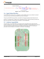
Figure 7. RGB LED Schematic Diagram
5.6. Input/Output Headers
The KL02Z32VLK4 microcontroller is packaged in an 32-pin QFN. Some pins are utilized in on-board
circuitry, but many are directly connected to one of four I/O headers.
The pins on the KL02Z microcontroller are named for their general purpose input/output port pin
function. For example, the 1st pin on Port A is referred to as PTA1. The I/O connector pin names are
given the same name as the KL02Z pin connected to it, where applicable.
5.7. Arduino Compatibility
The I/O headers on the FRDM-KL02Z are arranged to allow compatibility with peripheral boards
(known as shields) that connect to Arduino and Arduino-compatible microcontroller boards. The outer
rows of pins (the even numbered pins) on the headers share the same mechanical spacing and
placement as the I/O headers on the Arduino Uno Revision 3 board design.
Figure 8. FRDM-KL02 Pinout
FRDMKL02ZUM
FRDM-KL02Z User Manual
Page 9 of 11