1
1.3 Technical Specifications
Electrical and Mechanical Specifications
Supply voltage
10-24V
Current used in standby mode
120mA max
300mA max
GSM modem frequency
850/900/1800/1900 MHz
Supported protocols
CONTACT ID, 4+2*
Maximum number of users to whom SMS messages are delivered
5
Dimensions
130x73 mm
Operating temperature range
-20...+55oC
Generated phone line voltage
18 V
Generated phone line current
25 mA
Generated phone line impedance
600 Ohm
Dial tone of generated phone line
350 Hz
* When SMS mode is enabled, system doesn‘t support 4+2 protocol. 4+2 protocol works only with Monitoring Station Mode.
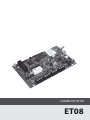
1.4 Block Circuit
For configurations
DEFAULT
SIM CARD
GSM
MODEM
SET
MODE
PROG
ANT
USB
INFO
B1
STATUS
GSM
B2
FUSE
500 mA
L1 L2
L3
L4 RING TIP
N.C. DC+ COM
N.C. N.C. N.C.
1.5 Connectors Functionality
Connector Functionality
Main Units
GSM MODEM
GSM network
850/900/1800/1900 MHz
modem
Labelling
Explanation
DC+
Power supply positive connector
COM
Common contact
Pin connected to the Alarm Control Panel pin RING
SIM CARD
SIM card holder
RING
ANT
GSM antenna SMA type
connector
TIP
Pin connected to the Alarm Control Panel pins TIP
L1-L4
Pins connected to landline or PBX according back-up mode
Resettable F1 type – miniSMDC
500mA
USB
Mini USB port
N.C.
Not connected
FUSE
USER MANUAL ELDES ET08 V1.0
5