1
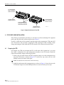
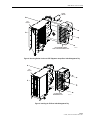
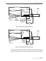
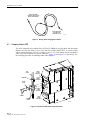
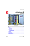
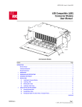
ADC Next Generation Frame™
96 & 144 Position Fiber Termination Block
User Manual
ADCP-90-287 • Issue 2 • 5/2009
1463926 Rev A
ADC Next Generation Frame™
96 & 144 Position Fiber Termination Block
User Manual
ADCP-90-287 • Issue 2 • 5/2009
1463926 Rev A
ADCP-90-287 • Issue 2 • 5/2009 • Preface
COPYRIGHT
© 2009, ADC Telecommunications, Inc.
All Rights Reserved
REVISION HISTORY
ISSUE
DATE
1
3/2002
Original.
REASON FOR CHANGE
2
5/2009
Add fiber specification and update illustrations.
LIST OF CHANGES
The technical changes incorporated into this issue are listed below.
PAGE
IDENTIFIER
v, 2, 23, 26
-
DESCRIPTION OF CHANGE
Add note on fiber diameter specification.
Figures
2, 6, 8, 9, 10, 20, 24, 25, 26, 27
TRADEMARK INFORMATION
ADC FiberGuide and are registered trademark of ADC Telecommunications, Inc.
Next Generation Frame is a trademark of ADC Telecommunications, Inc.
DISCLAIMER OF LIABILITY
Contents herein are current as of the date of publication. ADC reserves the right to change the contents without prior notice. In no
event shall ADC be liable for any damages resulting from loss of data, loss of use, or loss of profits and ADC further
disclaims any and all liability for indirect, incidental, special, consequential or other similar damages. This disclaimer of
liability applies to all products, publications and services during and after the warranty period.
This publication may be verified at any time by contacting ADC’s Technical Assistance Center at 1-800-366-3891, extension 73476
(in U.S.A. or Canada) or 952-917-3476 (outside U.S.A. and Canada), or by e-mail to [email protected]
ADC Telecommunications, Inc.
P.O. Box 1101, Minneapolis, Minnesota 55440-1101
In U.S.A. and Canada: 1-800-366-3891
Outside U.S.A. and Canada: (952) 938-8080
Fax: (952) 917-1717
Page ii
ADCP-90-287 • Issue 2 • 5/2009 • Preface
TABLE OF CONTENTS
Content
Page
ABOUT THIS MANUAL . . . . . . . . . . . . . . . . . . . . . . . . . . . . . . . . . . . . . . . . . . . . . . . . . . . . . . . . . . . . . . . . . . . . . . . . . v
RELATED PUBLICATIONS . . . . . . . . . . . . . . . . . . . . . . . . . . . . . . . . . . . . . . . . . . . . . . . . . . . . . . . . . . . . . . . . . . . . . . . v
ADMONISHMENTS . . . . . . . . . . . . . . . . . . . . . . . . . . . . . . . . . . . . . . . . . . . . . . . . . . . . . . . . . . . . . . . . . . . . . . . . . . . v
GENERAL SAFETY PRECAUTIONS . . . . . . . . . . . . . . . . . . . . . . . . . . . . . . . . . . . . . . . . . . . . . . . . . . . . . . . . . . . . . . . . . vi
LIST OF ACRONYMS AND ABBREVIATIONS . . . . . . . . . . . . . . . . . . . . . . . . . . . . . . . . . . . . . . . . . . . . . . . . . . . . . . . . . . . vi
1
OVERVIEW AND DESCRIPTION . . . . . . . . . . . . . . . . . . . . . . . . . . . . . . . . . . . . . . . . . . . . . . . . . . . . . . . . . . . . . . 1
1.1
1.2
1.3
Description. . . . . . . . . . . . . . . . . . . . . . . . . . . . . . . . . . . . . . . . . . . . . . . . . . . . . . . . . . . . . . . . . . . . . . 1
1.1.1
FTB Primary Function. . . . . . . . . . . . . . . . . . . . . . . . . . . . . . . . . . . . . . . . . . . . . . . . . . . . . . . . 1
1.1.2
FTB Primary Components . . . . . . . . . . . . . . . . . . . . . . . . . . . . . . . . . . . . . . . . . . . . . . . . . . . . . 2
1.1.3
Options That Affect Installation . . . . . . . . . . . . . . . . . . . . . . . . . . . . . . . . . . . . . . . . . . . . . . . . . 3
1.1.4
Accessories . . . . . . . . . . . . . . . . . . . . . . . . . . . . . . . . . . . . . . . . . . . . . . . . . . . . . . . . . . . . . . 4
Applications . . . . . . . . . . . . . . . . . . . . . . . . . . . . . . . . . . . . . . . . . . . . . . . . . . . . . . . . . . . . . . . . . . . . . 4
1.2.1
Interconnect Application. . . . . . . . . . . . . . . . . . . . . . . . . . . . . . . . . . . . . . . . . . . . . . . . . . . . . . 4
1.2.2
Cross-Connect Application . . . . . . . . . . . . . . . . . . . . . . . . . . . . . . . . . . . . . . . . . . . . . . . . . . . . 5
Specifications . . . . . . . . . . . . . . . . . . . . . . . . . . . . . . . . . . . . . . . . . . . . . . . . . . . . . . . . . . . . . . . . . . . . 6
2
UNPACKING AND INSPECTING THE PRODUCT . . . . . . . . . . . . . . . . . . . . . . . . . . . . . . . . . . . . . . . . . . . . . . . . . . . . 6
3
ADAPTER PACK INSTALLATION . . . . . . . . . . . . . . . . . . . . . . . . . . . . . . . . . . . . . . . . . . . . . . . . . . . . . . . . . . . . . . 6
4
5
6
7
3.1
Installing Adapter Packs . . . . . . . . . . . . . . . . . . . . . . . . . . . . . . . . . . . . . . . . . . . . . . . . . . . . . . . . . . . . . 6
3.2
Removing an Adapter Pack . . . . . . . . . . . . . . . . . . . . . . . . . . . . . . . . . . . . . . . . . . . . . . . . . . . . . . . . . . . 7
IFC OR OSP CABLE INSTALLATION . . . . . . . . . . . . . . . . . . . . . . . . . . . . . . . . . . . . . . . . . . . . . . . . . . . . . . . . . . . 8
4.1
Preparing the FTB . . . . . . . . . . . . . . . . . . . . . . . . . . . . . . . . . . . . . . . . . . . . . . . . . . . . . . . . . . . . . . . . . 8
4.2
Preparing Cable for Installation . . . . . . . . . . . . . . . . . . . . . . . . . . . . . . . . . . . . . . . . . . . . . . . . . . . . . . . 10
4.3
Clamping Cable to FTB . . . . . . . . . . . . . . . . . . . . . . . . . . . . . . . . . . . . . . . . . . . . . . . . . . . . . . . . . . . . . 12
4.4
Routing and Connecting Cable Fibers Within FTB . . . . . . . . . . . . . . . . . . . . . . . . . . . . . . . . . . . . . . . . . . . 15
FTB INSTALLATION . . . . . . . . . . . . . . . . . . . . . . . . . . . . . . . . . . . . . . . . . . . . . . . . . . . . . . . . . . . . . . . . . . . . . 17
5.1
Mounting FTB On Rack . . . . . . . . . . . . . . . . . . . . . . . . . . . . . . . . . . . . . . . . . . . . . . . . . . . . . . . . . . . . . 18
5.2
Securing IFC or OSP Cable to Rack . . . . . . . . . . . . . . . . . . . . . . . . . . . . . . . . . . . . . . . . . . . . . . . . . . . . 21
FOT EQUIPMENT PATCH CORD INSTALLATION . . . . . . . . . . . . . . . . . . . . . . . . . . . . . . . . . . . . . . . . . . . . . . . . . . 23
6.1
Terminating Patch Cord at FTB. . . . . . . . . . . . . . . . . . . . . . . . . . . . . . . . . . . . . . . . . . . . . . . . . . . . . . . . 23
6.2
Installing FOT Equipment Patch Cords—Overhead Without FOTSB . . . . . . . . . . . . . . . . . . . . . . . . . . . . . . . 26
6.3
Installing FOT Equipment Patch Cords—Overhead With FOTSB . . . . . . . . . . . . . . . . . . . . . . . . . . . . . . . . . 28
6.4
Installing FOT Equipment Patch Cords—Underfloor Without FOTSB . . . . . . . . . . . . . . . . . . . . . . . . . . . . . . 30
6.5
Installing FOT Equipment Patch Cords—Underfloor With FOTSB . . . . . . . . . . . . . . . . . . . . . . . . . . . . . . . . 32
CUSTOMER INFORMATION AND ASSISTANCE . . . . . . . . . . . . . . . . . . . . . . . . . . . . . . . . . . . . . . . . . . . . . . . . . . . 34
Page iii
© 2009, ADC Telecommunications, Inc.
ADCP-90-287 • Issue 2 • 5/2009 • Preface
TABLE OF CONTENTS
Content
Page
Blank
Page iv
© 2009, ADC Telecommunications, Inc.
ADCP-90-287 • Issue 2 • 5/2009 • Preface
ABOUT THIS MANUAL
This user manual provides the following information:
• A description of the 96 & 144 position Fiber Termination Blocks (FTBs); their
components and terminology, typical applications, and typical accessories;
• Procedures for installing an FTB on any of the Next Generation Frame (NGF) racks;
• Procedures for terminating connectorized Outside Plant (OSP) cables, Intra-Facility
Cables (IFC), or Fiber Optic Terminal (FOT) equipment patch cords at the FTB.
Note: The NGF Fiber Termination Blocks (FTBs) are designed to be used with 1.7mm or
2.0mm patchcords. 3.0mm patchcords should never be used due to the bulk build-up in the
NGF solution.
The procedures for installing the various NGF racks, including the Fiber Main Distribution Frame
(FMDF), the Front Facing Fiber Main Distribution Frame (F3MDF), and the Slim Rack Fiber
Distribution Frame, are provided in other ADC publications (see “Related Publications,” below).
RELATED PUBLICATIONS
Listed below are related manuals, their content, and their publication numbers. Copies of these
publications can be ordered by contacting the Technical Assistance Center at 1-800-366-3891,
extension 73476 (in U.S.A. or Canada) or 952-917-3476 (outside U.S.A. and Canada).
Title/Description
ADCP Number
Next Generation Frame Fiber Main Distributing Frame User Manual
Provides a complete description of the FMDF and procedures for installing the
FMDF rack, the FTB, and the FCB.
90-273
Next Generation Frame Slim Rack Fiber Distributing Frame User Manual
Provides a complete description of the slim rack frame and procedures for
installing the FMDF rack, the FTB, and the FCB.
90-272
Next Generation Frame Fiber Combination Block User Manual
Provides instructions for installing the FCB in the NGF rack.
90-279
Next Generation Frame Fiber Optic Terminal Storage Bay User Manual
Provides instructions for installing the FOTSB with the FMDF rack.
90-270
ADMONISHMENTS
Important safety admonishments are used throughout this manual to warn of possible hazards to
persons or equipment. An admonishment identifies a possible hazard and then explains what
may happen if the hazard is not avoided. The admonishments — in the form of Dangers,
Warnings, and Cautions — must be followed at all times.
Page v
© 2009, ADC Telecommunications, Inc.
ADCP-90-287 • Issue 2 • 5/2009 • Preface
These warnings are flagged by use of the triangular alert icon (seen below), and are listed in
descending order of severity of injury or damage and likelihood of occurrence.
Danger: Danger is used to indicate the presence of a hazard that will cause severe personal
injury, death, or substantial property damage if the hazard is not avoided.
Warning: Warning is used to indicate the presence of a hazard that can cause severe personal
injury, death, or substantial property damage if the hazard is not avoided.
Caution: Caution is used to indicate the presence of a hazard that will or can cause minor
personal injury or property damage if the hazard is not avoided.
GENERAL SAFETY PRECAUTIONS
Danger: Infrared radiation is invisible and can seriously damage the retina of the eye. Do not
look into the ends of any optical fiber. Do not look directly into the optical adapters of the adapter
packs. Exposure to invisible laser radiation may result. An optical power meter should be used to
verify active fibers. A protective cap or hood MUST be immediately placed over any radiating
adapter or optical fiber connector to avoid the potential of dangerous amounts of radiation
exposure. This practice also prevents dirt particles from entering the adapter or connector.
LIST OF ACRONYMS AND ABBREVIATIONS
The following acronyms are used in this manual:
FCB
FMDF
FOT
FOTSB
FTB
F3MDF
IFC
NGF
OSP
VAM
Page vi
© 2009, ADC Telecommunications, Inc.
Fiber Combination Block
Fiber Main Distributing Frame
Fiber Optic Terminal
Fiber Optic Terminal Storage Bay
Fiber Termination Block
Front Facing Fiber Main Distributing Frame
Intra-Facility Fiber Cable
Next Generation Frame
Outside Plant
Value Added Module
ADCP-90-287 • Issue 2 • 5/2009
1
OVERVIEW AND DESCRIPTION
This section describes the ADC 96 & 144 position Fiber Termination Blocks (FTBs) and
explains their basic applications. This section also contains product specifications. The 96 &
144 position FTBs have many common features. Statements made in this manual regarding the
FTB alone, without reference to number of positions, pertain to both types.
1.1
Description
1.1.1
FTB Primary Function
FTBs are used in conjunction with an NGF rack (FMDF, F3MDF, or Slim Rack) to provide a
point for terminating connectorized fiber optic cables and for interconnecting or crossconnecting the terminated circuits using patch cords. Figure 1 shows two FTBs and a frame.
17414-A
Figure 1. Fiber Termination Blocks and Frame
Page 1
© 2009, ADC Telecommunications, Inc.
ADCP-90-287 • Issue 2 • 5/2009
Connectorized OSP and IFC cables and FOT equipment patch cords terminate at the rear of the
FTB. Cross-connect or interconnect patch cords connect to the front of the FTB. The FTB
mounts on the NGF rack, which provides physical support and cable management. The FTB has
a left or right orientation for installation on either the left or right side of the frame (as viewed
from the front). In addition, the FTB also has a top or bottom cable exit orientation.
Note: The NGF Fiber Termination Blocks (FTBs) are designed to be used with 1.7mm or
2.0mm patchcords. 3.0mm patchcords should never be used due to the bulk build-up in the
NGF solution.
1.1.2
FTB Primary Components
An FTB consists of a sheet metal chassis that houses rows of sliding adapter packs and the
necessary cable management for routing the fiber optic cables within the chassis. The 96 position
chassis, shown in Figure 2, accepts sliding adapter packs that contain four adapters each, while the
144 position chassis accepts sliding adapter packs that contain six adapters each. The adapter packs
are available with SC, FC, ST, and E-2000 adapters that provide 96 or 144 terminations per FTB.
Adapter packs are also available with LX.5 adapters which can provide up to 144 terminations.
UPPER
RADIUS
LIMITER
REAR CABLE
MANAGEMENT
AREA
SLIDING
ADAPTER
PACKS
SIDE
COVER
23474-A
HINGED
FRONT
COVERS
LOWER
RADIUS
LIMITER
FRONT
RADIUS
LIMITERS
Figure 2. Fiber Termination Block (96 Position Chassis Shown)
Page 2
© 2009, ADC Telecommunications, Inc.
ADCP-90-287 • Issue 2 • 5/2009
The FTB chassis includes a removable side cover and two hinged front covers. Removing the
side cover provides access to the rear cable management area (see Figure 2). The rear cable
management area includes features for clamping and routing OSP/IFC cables and equipment
jumpers, and a spool for storing fiber slack. Opening the FTB front covers provides access to
the adapter packs (by sliding them out) and to the front radius limiters which facilitate the
routing of interconnect or cross-connect patch cords. The front covers also include designation
labels to identify the optical circuits.
1.1.3
Options That Affect Installation
The following FTB ordering options may affect the installation process:
• The FTB may be ordered in either a pre-terminated or adapter only version. In the preterminated version, shown in Figure 3, the FTB is equipped with an installed OSP or IFC
cable. One end of the cable is connected to the rear side of the adapters within the FTB. The
other end of the OSP/IFC cable is coiled on a spool. At the job site, the free end of the OSP/
IFC cable must be uncoiled from the spool and then routed to another location for splicing
or connection to the OSP or FOT equipment circuits. The adapter only FTB is loaded with
adapters only and does not include a pre-terminated OSP or IFC cable. The adapter only
FTB is typically used to terminate FOT patch cords in a cross-connect application.
Figure 3. 144 Position Pre-Terminated FTB in Down Configuration
• The FTB may be ordered with a top or bottom exit orientation for the OSP/IFC cable or
FOT equipment patch cords. With the top (“up”) exit orientation, the OSP/IFC cable or
FOT equipment patch cords must be routed out of the FTB toward the top of the frame.
With the bottom (“down”) exit orientation, the OSP/IFC cable or FOT equipment patch
cords must be routed out of the FTB toward the bottom of the frame.
Page 3
© 2009, ADC Telecommunications, Inc.
ADCP-90-287 • Issue 2 • 5/2009
• The FTB may be ordered with a left or right orientation. The left-orientation FTB installs
on the left side of the frame (when facing the front of the frame); the right-orientation FTB
installs on the right side of the frame.
1.1.4
Accessories
The following accessories are available for use with the FTB:
• Cable Clamp Kits—Provide a clamp and other hardware required for securing IFC or
OSP cables to the rear side of the FTB.
• IFC Cable Assemblies—Are available with singlemode or multimode fiber in specified
lengths and with specified connectors.
• Patch Cords—Are available with specified connectors in standard lengths of 6.0, 7.0, 8.0,
9.0, 10.0, and 12.0 meters.
• Adapter Packs—Are available separately with specified adapters, and can be used as
either as replacements for existing adapter packs or to add termination capacity. Each FTB
provides 24 adapter pack mounting slots.
• In-Line Attenuators—Install between an adapter and connector. Can be mounted on
either the front side or the rear side of an adapter pack.
• Connector Cleaning Kit—Provides all the materials required to correctly clean fiber
optic connectors and adapters.
1.2
Applications
The FTB may be used to support either interconnect or cross-connect frame applications. Both
are described below.
1.2.1
Interconnect Application
In an interconnect application, only the OSP circuits are terminated at the rear of the frame. The
FOT equipment is connected directly to the OSP terminations using interconnect patch cords.
The excess patch cord slack is stored in the slack storage area on the front of the frame. Figure 4
shows a typical interconnect application using the FMDF. An interconnect application uses the
entire frame for terminating OSP circuits. An overhead or underfloor fiber raceway system such
as the FiberGuide system must be used for routing the interconnect patch cords to the frame.
Page 4
© 2009, ADC Telecommunications, Inc.
ADCP-90-287 • Issue 2 • 5/2009
FOT EQUIPMENT
PATCH CORD
FOT EQUIPMENT
PATCH CORD
CONNECTORIZED
IFC CABLE
FTB
OSP
CABLE
FCB
PIGTAIL
T
T
ON
FR
ON
FR
ADAPTER
SPLICE
INTERCONNECT WITH OSP
CABLE TERMINATED AT FCB
INTERCONNECT WITH IFC
CABLE TERMINATED AT FTB
17115-A
17115-B
Figure 4. Typical Interconnect Application
1.2.2
Cross-Connect Application
In a cross-connect application, both FOT equipment circuits and OSP circuits are terminated at
the rear of the frame. An FOT equipment circuit may be connected to an OSP circuit, an FOT
equipment circuit may be connected to another FOT equipment circuit, or an OSP circuit may
be connected to another OSP circuit, using a cross-connect patch cord. The excess patch cord
slack is stored in the slack area on the front of the frame. Figure 5 shows a typical cross-connect
application using the FMDF.
FOT EQUIPMENT
PATCH CORD
FOT EQUIPMENT
PATCH CORD
FTB
CONNECTORIZED
IFC CABLE
FTB
CROSS-CONNECT
PATCH CORD
FTB
CROSS-CONNECT
PATCH CORD
OSP
CABLE
FCB
T
ON
FR
CROSS-CONNECT WITH IFC CABLE
TERMINATED AT FTB AND FOT EQUIPMENT
PATCH CORDS TERMINATED AT FTB
T
ON
FR
PIGTAIL
ADAPTER
SPLICE
CROSS-CONNECT WITH OSP CABLE
TERMINATED AT FCB AND FOT EQUIPMENT
PATCH CORDS TERMINATED AT FTB
17133-B
Figure 5. Typical Cross-Connect Application
Page 5
© 2009, ADC Telecommunications, Inc.
ADCP-90-287 • Issue 2 • 5/2009
1.3
Specifications
Table 1 provides specifications for the FTB.
Table 1. FTB Specifications
PARAMETER
SPECIFICATION
REMARKS
Physical
Number of Terminations
96 or 144
Connector types
SC, FC, ST, E-2000, or LX.5
Environment
Temperature
Operating
–40° C to 65° C (–40° F to149° F)
Storage
–55° C to 85° C (–67° F to185° F)
Relative Humidity
2
Operating
Up to 80%
No condensation
Storage
Up to 95%
No condensation
UNPACKING AND INSPECTING THE PRODUCT
Use the following procedure to unpack and inspect the FTB:
1. Inspect the exterior of the shipping container for evidence of rough handling that may have
damaged the contents of the container.
2. Unpack the FTB and inspect for possible damage.
3. If damage is detected or if parts are missing, file a claim with the commercial carrier and
then notify ADC Customer Service. Save damaged carton for inspection by carrier.
4. Refer to Section 7 of this publication (see Product Return Department) for repair,
replacement, and warranty information.
5. Even if no damage is evident, save the shipping container in case the equipment requires
shipment at a future date.
3
ADAPTER PACK INSTALLATION
Adapter packs may be ordered separately and installed in the FTB as needed. If this is the case
in your installation, install the adapter packs before mounting the FTB on the rack.
3.1
Installing Adapter Packs
Use the following procedure to install adapter packs in the FTB:
1. Open the FTB front covers and locate the adapter pack mounting slots.
Page 6
© 2009, ADC Telecommunications, Inc.
ADCP-90-287 • Issue 2 • 5/2009
2. Orient the adapter pack for installation as shown in Figure 6.
SLIDING ADAPTER PACK
(LEFT ORIENTATION)
SLIDING ADAPTER PACK
(RIGHT ORIENTATION)
23475-A
Figure 6. Adapter Pack Orientation and Installation in FTB
3. Insert the adapter pack into the designated mounting slot and slide it inward until it clicks
into place.
Note: Each row holds two adapter packs. The left pack installs in the mounting slot from
the left side and the right pack installs in the mounting slot from the right side. The end of
the adapter pack without the rotating handle should be inserted into the mounting slot first.
4. Repeat the installation procedure for each adapter pack.
3.2
Removing an Adapter Pack
If it is necessary to remove one or more adapter packs, use the following procedure. Refer to
Figure 7.
1. Rotate the rotating handle outward to grasp the adapter pack.
2. Slide the adapter pack out until it contacts the internal detent and continue pulling to
release the pack from the mounting slot.
Page 7
© 2009, ADC Telecommunications, Inc.
ADCP-90-287 • Issue 2 • 5/2009
2. SLIDE ADAPTER
PACK OUTWARD TO
DETENT POSITION
1. ROTATE HANDLE
OUTWARD TO EJECT
2. SLIDE ADAPTER
PACK OUTWARD TO
DETENT POSITION
3. PULL OUTWARD ON
INSIDE TAB TO RELEASE
FROM DETENT POSITION
1. ROTATE HANDLE
OUTWARD TO EJECT
17347-A
Figure 7. Adapter Pack Removal From FTB
4
IFC OR OSP CABLE INSTALLATION
If the FTB is pre-terminated by the factory or will only be used for terminating FOT equipment
patch cords, skip this entire section and proceed to Section 5.
If an IFC or OSP cable will be installed, install the cable before mounting the FTB in the NGF
rack. This involves four procedures: preparing the FTB, preparing the cable, installing a cable
clamp, and routing the cable within the FTB. For details, refer to the next four topics below.
4.1
Preparing the FTB
If an adapter only FTB was purchased and IFC or OSP cable will be loaded into it, you must
first install a replacement rear cable management assembly in the FTB chassis. Install the
replacement assembly using the following procedure.
1. Remove the rear radius limiter and FOT equipment jumper rear cable management tray
from the FTB chassis, as shown in Figure 8. To remove the tray, remove the six #4-40
Phillips head screws shown in the figure.
Note: Set aside the six screws for use in the next step.
2. Install the replacement cable management tray as shown in Figure 9. Secure the tray to the
FTB chassis using the six #4-40 Phillips head screws removed in the previous step.
Page 8
© 2009, ADC Telecommunications, Inc.
ADCP-90-287 • Issue 2 • 5/2009
RADIUS
LIMITER
FTB
CHASSIS
FOT EQUIPMENT JUMPER
REAR CABLE MANAGEMENT TRAY
23476-A
Figure 8. Removing Radius Limiter and FOT Equipment Jumper Rear Cable Management Tray
FTB
CHASSIS
IFC REAR CABLE
MANAGEMENT TRAY
23477-A
Figure 9. Installing the IFC Rear Cable Management Tray
Page 9
© 2009, ADC Telecommunications, Inc.
ADCP-90-287 • Issue 2 • 5/2009
3. Install the IFC cable clamp bracket as shown in Figure 10 using the three screws and lock
washers provided.
FTB
IFC CABLE
CLAMP
BRACKET
23479-A
Figure 10. Installing the IFC Cable Clamp Bracket
4.2
Preparing Cable for Installation
After installing the IFC cable management tray and the IFC cable clamp bracket, you can
proceed to prepare the IFC or OSP cable for installation. IFC or OSP cables purchased from
ADC for installation in the FTB are pre-dimensioned and do not require any special preparation
prior to installation. If the IFC or OSP cables are not purchased from ADC, prepare the cables
for installation using the breakout dimensions shown in Figure 11 and Figure 12.
Before the IFC or OSP cable is clamped to the FTB, the cable may be routed and installed
within the building or it may coiled up near the frame for routing and installation after the FTB
is installed in the frame.
If the cable will be routed and installed before it is clamped to the FTB, leave sufficient slack at
the frame end of the cable for installing the FTB in the NGF rack.
Page 10
© 2009, ADC Telecommunications, Inc.
ADCP-90-287 • Issue 2 • 5/2009
BREAKOUT LENGTH
(54.5 +0.0 -4.0 INCH) (138.4 +0.0 -10.2 CM)
END OF
PROTECTIVE
TUBE
FANOUT LENGTH
(44.5 +0.0 -4.0 INCH)
(113.0 +0.0 -10.2 CM)
1.0 INCH
(2.54 CM)
REF
OSP/IFC
CABLE
CLAMP
INSTALL PROTECTIVE
TUBES ON RIBBON
FANOUT CHIP
17314-A
CONNECTORS
INDIVIDUAL
FIBERS
(UPJACKETED
TO 900 MICRONS)
TAPE TUBES TOGETHER
AND SURROUND WITH
CONVOLUTED TUBING
BEFORE APPLYING
HEATSHRINK.
2.0 INCH (5.08 CM)
HEATSHRINK PAST
CABLE JACKET
HEATSHRINK
6.0 INCH
+0.5 -0.5 INCH
(15.2 CM +1.3 -1.3 CM)
REF
Figure 11. OSP/IFC Ribbon Cable Breakout Dimensions
BREAKOUT LENGTH
(54.5 +0.0 -4.0 INCH) (138.4 +0.0 -10.2 CM)
FANOUT LENGTH
(42.5 +0.0 -4.0 INCH)
(108 +0.0 -10.2 CM)
CONNECTORS
END OF
BUFFER
TUBE
2.0 INCH
(5.08 CM)
HEATSHRINK
PAST CABLE
JACKET
1.0 INCH
(2.54 CM)
REF
OSP/IFC
CABLE
CLAMP
17315-A
HEATSHRINK
6.0 INCH
+0.5 -0.5 INCH
(15.2 CM +1.3 -1.3 CM)
REF
Figure 12. OSP/IFC Stranded Cable Breakout Dimensions
If the cable will be routed and installed after it is clamped to the FTB, remove the cable from its
spool and then coil it up in a figure 8 pattern as shown in Figure 13, starting with the end that
connects to the FTB. Make sure the end of the cable that does not connect to the FTB is coiled last.
Page 11
© 2009, ADC Telecommunications, Inc.
ADCP-90-287 • Issue 2 • 5/2009
FINISH WITH END
THAT WILL BE ROUTED
AWAY FROM FRAME
START WITH END
THAT WILL BE
CLAMPED TO FTB
17119-A
Figure 13. Storing Cable Using Figure 8 Pattern
4.3
Clamping Cable to FTB
Two ADC clamp kits are available. Kit # NGF-ACCCLMP08 is used for cables with an outside
diameter of 0.4 to 0.8 inches (1.01 to 2.03 mm). Kit # OSP-CLPSST-IFCL is used for cables
with an outside diameter of 0.8 to 1.2 inches (2.03 to 3.05). Cable clamps may be installed in
either a top exit or bottom exit position (shown in Figure 14 and Figure 15, respectively). Use
the following procedure for installing either cable clamp kit.
OSP
CABLE
GROMMET
CABLE
CLAMP
POSITION 1
CABLE
CLAMP
POSITION 2
COVER
PLATE
CABLE
CLAMP
POSITION 3
SCREWS
RUBBER
YOKES
CABLE
CLAMP
POSITION 4
17420-A
Figure 14. Top Exit IFC/OSP Cable Clamp Installation
Page 12
© 2009, ADC Telecommunications, Inc.
ADCP-90-287 • Issue 2 • 5/2009
CABLE
CLAMP
POSITION 4
CABLE
CLAMP
POSITION 3
CABLE
CLAMP
POSITION 2
COVER
PLATE
17421-A
CABLE
CLAMP
POSITION 1
SCREWS
GROMMET
RUBBER
YOKES
OSP
CABLE
Figure 15. Bottom Exit IFC/OSP Cable Clamp Installation
1. Locate the cable clamp mounting position at the rear side of the FTB. Note that four
clamping positions are provided for both top exit and bottom exit positions (shown in
Figure 14 and Figure 15, respectively).
Note: If more than one cable will be attached to the FTB, use the clamping positions in the
order shown.
2. Remove the side cover from the FTB.
3. Verify that the FTB has the correct cable exit orientation (top or bottom) for the cable
installation, as shown in Figure 16.
Page 13
© 2009, ADC Telecommunications, Inc.
ADCP-90-287 • Issue 2 • 5/2009
CABLE EXITS
UPWARD
TOP EXIT ASSEMBLY
BOTTOM EXIT ASSEMBLY
17316-A
CABLE EXITS
DOWNWARD
Figure 16. Cable Exit Orientation
4. Two rubber yokes and either three or four grommets (depending on the kit) are provided
with the cable clamp kit for securing the cable to the FTB. Select the grommet that, when
placed on the cable, results in the gap width shown in Figure 17.
Page 14
© 2009, ADC Telecommunications, Inc.
ADCP-90-287 • Issue 2 • 5/2009
Figure 17. Grommet Selection
5. Place the rubber clamp yokes and the grommet selected in step 4 around the cable and then
secure the cable to the FTB (see Figure 14 and Figure 15).
Note: If each of the grommets measured in step 4 have a gap that exceeds 0.30 inches (7.6
mm), a grommet is not required.
6. Repeat this procedure for each cable being installed.
4.4
Routing and Connecting Cable Fibers Within FTB
After the IFC or OSP cable is clamped to the FTB, use the following procedure to route and
connect the cable fibers within the FTB and to store any excess slack. Refer to Figure 18 if the
cable exits the FTB toward the top or Figure 19 if the cable exits the FTB toward the bottom.
1. Route the OSP/IFC cable fiber ribbon (if ribbon cable) or fiber sub-unit (if stranded cable)
to the break-out point within the FTB.
2. Route the fibers from the fan-out chip or fiber sub-unit once around the storage spool
forming a slack loop.
3. From the top of the storage spool, route the fibers to the rear side of the adapter pack for
the first group of circuits.
Note: If the cable being installed exits the FTB toward the top, start with circuits assigned
to the top row of adapter packs. If the cable exits the FTB toward the bottom, start with
circuits assigned to the bottom row of adapter packs.
4. Rotate the adapter pack handle outward to grasp the adapter pack. Pull out the adapter
pack into the accessible position.
Page 15
© 2009, ADC Telecommunications, Inc.
ADCP-90-287 • Issue 2 • 5/2009
ROUTE FROM
TOP TO BOTTOM
BREAKOUT
POINT
ROUTE FIBERS FOR TOP SEVEN
ROWS INSIDE RADIUS LIMITER
17337-A
RADIUS
LIMITER
O-RING
SLACK
LOOP
ROUTE FIBERS FOR BOTTOM FIVE
ROWS OUTSIDE RADIUS LIMITER
Figure 18. Top Exit Cable Routing
17336-A
ROUTE FROM
BOTTOM TO TOP
O-RING
BREAKOUT
POINT
SLACK
LOOP
Figure 19. Bottom Exit Cable Routing
5. Slide the adapter pack outward to provide access to the rear side of the adapters as shown
in Figure 20.
Page 16
© 2009, ADC Telecommunications, Inc.
ADCP-90-287 • Issue 2 • 5/2009
ROTATE HANDLE OUTWARD
TO EJECT ADAPTER PACK.
SLIDE ADAPTER PACK OUTWARD
TO ACCESS ADAPTERS.
23480-A
Figure 20. Accessing Adapter Packs in FTB
6. Remove the dust cover from each adapter and connect each fiber connector to the
appropriate adapter.
7. Slide the adapter pack back to the center position and snap in the adapter pack handle.
8. Adjust the fiber storage loop to take up all excess fiber slack.
Note: The fiber slack should hang loosely below the spool and should not be wound
tightly around the spool.
9. Use the basic process outlined in steps 1–8 to route and connect the fibers from each fiber
ribbon or fiber sub-unit.
10. Install the O-ring at the fiber break-out point to secure the fan-out chips or fiber sub-units
to the FTB.
5
FTB INSTALLATION
After the FTB has been prepared as described in Section 4, you can proceed to this section to
mount the FTB on the frame.
Page 17
© 2009, ADC Telecommunications, Inc.
ADCP-90-287 • Issue 2 • 5/2009
5.1
Mounting FTB On Rack
Use the following procedure to mount the FTB on the NGF rack:
1. If the FTB does not have an IFC/OSP cable attached or if an IFC/OSP cable was attached
to the FTB following the instructions in Section 4.3, proceed to step 7. If the FTB is preterminated by the factory and mounted on a spool assembly, proceed to step 2.
2. Place the cable spool with the enclosed pre-terminated FTB next to the NGF rack and then
position the spool so it is supported by the two plywood side supports.
Note: The FTB is mounted inside the cable spool and is designed to rotate as the cable is
unwound from the spool.
3. Unwind the free end of the cable from the spool, and then route and install the cable within
the building as required by the application. Leave sufficient slack at the frame end of the
cable for mounting the FTB in the NGF rack.
4. When all of the cable is unwound from the spool, place the cable spool on its side with the
smaller of the two plywood side supports facing up, as shown in Figure 21.
5. Remove the four wing nuts from the side of the spool, and then lift the spool side support
assembly off the spool.
6. Remove the two foam packing blocks from the top of the FTB, and then carefully lift the
FTB out from the center of the spool.
7. Locate the designated mounting position for the FTB. In a new rack installation, the rack
may be populated by starting at the bottom and working toward the top or by starting at the
top and working toward the bottom. Left-oriented FTBs mount only on the left side of the
rack and right-oriented FTBs mount only on the right side of the rack.
install
Note: If installing a 144 position FTB with SC, FC, E2000, or ST adapters, you may have
to install a mounting bracket on the frame. If a mounting bracket was provided with the
FTB, install it per the instructions provided with it.
Page 18
© 2009, ADC Telecommunications, Inc.
ADCP-90-287 • Issue 2 • 5/2009
WING NUTS
(4 PLACES)
FOAM
PACKING
BLOCKS
FTB (SHOWN
WITHOUT CABLE
ATTACHED)
FOAM
PACKING
BLOCK
SPOOL
17415-A
Figure 21. Pre-Terminated FTB Spool Assembly
8. Slide the FTB onto the appropriate mounting bracket at the front of the rack as shown in
Figure 22.
Page 19
© 2009, ADC Telecommunications, Inc.
CDA
CDA
6
6
CDA
CDA
6
6
CDA
CDA
6
6
CDA
CDA
6
6
CDA
CDA
6
CDA
6
CDA
6
CDA
6
6
CDA
CDA
6
6
CDA
CDA
6
6
CDA
CDA
6
6
CDA
CDA
6
6
CDA
6
CDA
6
CDA
6
ADCP-90-287 • Issue 2 • 5/2009
15037-A
Figure 22. FTB Installation on Rack
9. Secure the FTB to the rack mounting bracket using the two #12-24 screws provided.
10. If an IFC/OSP cable is attached to the FTB, place the cable between the FTB mounting
brackets and the vertical cable brackets.
11. Repeat steps 1–10 for each FTB.
Page 20
© 2009, ADC Telecommunications, Inc.
ADCP-90-287 • Issue 2 • 5/2009
5.2
Securing IFC or OSP Cable to Rack
The method used for securing cables to the frame is determined by the whether the cables enter
the rack at the top or the bottom. Refer to Figure 23 for the recommended method for placing
and securing cables to the rack based on how the cables enter.
Page 21
© 2009, ADC Telecommunications, Inc.
ADCP-90-287 • Issue 2 • 5/2009
TOP ENTRY
FOR TOP ENTRY, PLACE AND
SECURE CABLES AS SHOWN.
FRAME MAY BE POPULATED
FROM THE BOTTOM OR TOP.
1
2
3
4
5
6
CABLE TIE
BRACKET
IFC
ALTERNATE
CABLE
CUT-OUT FOR
CABLE TIE
USE WAX STRING
OR CABLE TIES
(PER LOCAL PRACTICE)
TO SECURE CABLE TO
CABLE TIE BRACKET
FTB MOUNTING
BRACKET
CABLE CLAMP USED
TO SECURE IFC CABLE
TO REAR SIDE OF FTB
6
5
4
3
2
FTB 1
FTB 1
FTB 2
FTB 2
FTB 3
FTB 3
FTB 4
FTB 4
FTB 5
FTB 5
FTB 6
FTB 6
1
FOR BOTTOM ENTRY, PLACE
AND SECURE CABLES AS SHOWN.
FRAME MAY BE POPULATED
FROM THE BOTTOM OR TOP.
BOTTOM ENTRY
Figure 23. Securing IFC or OSP Cables to the NGF Rack
Page 22
© 2009, ADC Telecommunications, Inc.
17416-A
ADCP-90-287 • Issue 2 • 5/2009
6
FOT EQUIPMENT PATCH CORD INSTALLATION
When required by the application, patch cords (instead of an IFC or OSP cable) may be used to
terminate FOT equipment circuits at the FTB. This section provides procedures for terminating
the FOT patch cords at the FTB, routing them to the FOT equipment through either an overhead
or underfloor fiber raceway system, and securing them at the NGF rack. The FTB should be
installed on the NGF frame (see Section 4) before starting this series of procedures.
6.1
Terminating Patch Cord at FTB
Note: The NGF Fiber Termination Blocks (FTBs) are designed to be used with 1.7mm or
2.0mm patchcords. 3.0mm patchcords should never be used due to the bulk build-up in the
NGF solution.
The patch cord being installed may be either single, dual, or multiple-fiber. Begin installation by
terminating the patch cord at the FTB as described in the following procedure. Then refer to
sub-section 6.2, 6.3, 6.4, or 6.5 (whichever applies) for routing the patch cord between the NGF
frame and the FOT equipment.
1. If the patch cord is multiple-fiber, break it out for installation using a breakout length of
29-35 inches (74-89 cm). If the patch cord is single or dual, no breakout is required.
2. Locate the FTB within the NGF rack and remove the FTB side cover to provide access to
the inside of the FTB chassis.
RADIUS LIMITER
MOUNTED ON
TOP OF FTB
23481-A
Figure 24. FOT Patch Cord Internal FTB Routing
Top Entry, Single or Dual Patch Cord (Left-Oriented FTB Shown)
Page 23
© 2009, ADC Telecommunications, Inc.
ADCP-90-287 • Issue 2 • 5/2009
RADIUS LIMITER
MOUNTED ON
TOP OF FTB
SLACK
LOOP AS
NECESSARY
23482-A
Figure 25. FOT Patch Cord Internal FTB Routing
Top Entry, Multiple Fiber Patch Cord (Left-Oriented FTB Shown)
RADIUS LIMITER
MOUNTED ON
BOTTOM OF FTB
Figure 26. FOT Patch Cord Internal FTB Routing
Bottom Entry, All Patch Cords (Left-Oriented FTB Shown)
Page 24
© 2009, ADC Telecommunications, Inc.
23483-A
ADCP-90-287 • Issue 2 • 5/2009
3. If using an overhead fiber raceway system, route the patch cord into the FTB from the top
as shown in Figure 24 (if installing a single or dual patch cord) or Figure 25 (if installing a
multiple fiber patch cord). If using an underfloor system, route the patch cord into the FTB
from the bottom as shown in Figure 26.
4. Locate the adapter pack that houses the adapter for the required termination.
5. Rotate the adapter pack handle outward to grasp the adapter pack.
6. Slide the adapter pack outward to provide access to the rear side of the adapters as shown
in Figure 27.
ROTATE HANDLE OUTWARD
TO EJECT ADAPTER PACK.
SLIDE ADAPTER PACK OUTWARD
TO ACCESS ADAPTERS.
23480-A
Figure 27. Access Adapter Packs in FTB
7. Remove the cover from the adapter, and then connect the patch cord connector to the
appropriate adapter.
8. Use the basic process outlined in steps 1–7 for routing and terminating each FOT
equipment patch cord at the FTB.
9. Install an O-ring on the cable clamp to secure the patch cords.
10. Slide the adapter pack back into the FTB and snap in the adapter pack handle.
Note: Ensure that sufficient slack is allowed for movement of adapter packs in the slack
storage area of the FTB rear cable management.
Page 25
© 2009, ADC Telecommunications, Inc.
ADCP-90-287 • Issue 2 • 5/2009
6.2
Installing FOT Equipment Patch Cords—Overhead Without FOTSB
Note: The NGF Fiber Termination Blocks (FTBs) are designed to be used with 1.7mm or
2.0mm patchcords. 3.0mm patchcords should never be used due to the bulk build-up in the
NGF solution.
Use the following procedure to install FOT equipment patch cords when an overhead fiber
raceway system will be used for routing and when a Fiber Optic Terminal Storage Bay (FOTSB)
is not provided at the frame. Refer to Figure 28 for a diagram of the routing procedure.
1. Terminate the FOT equipment patch cords at the FTB as described in Section 6.1.
Note: Start with either the highest or lowest FTB and continue working in order from topto-bottom or from bottom-to-top as each FTB is terminated.
2. Route the patch cord through the vertical channel at the side of the frame and into the
overhead raceway system at the top of the frame.
3. Route the patch cord through the overhead raceway system to the FOT equipment.
4. Connect the patch cord to the FOT equipment.
5. Accumulate and store the excess patch cord length at the FOT equipment.
6. Repeat steps 1–5 as each FTB is terminated.
Page 26
© 2009, ADC Telecommunications, Inc.
ADCP-90-287 • Issue 2 • 5/2009
OVERHEAD GUIDEWAY SYSTEM
4
4
5
5
3
NOTE: SEE SUB-SECTION 5.2
FOR NUMBERED STEPS
3
2
1
FRAME
VERTICAL
CHANNEL
2
1
FRAME
FOT EQUIPMENT
PATCH CORDS
NOTE: SHOWN WITHOUT
DISTRIBUTION TROUGH
FOR CLARITY
17345-A
Figure 28. Overhead FOT Equipment Patch Cord Installation (Without FOTSB)
Page 27
© 2009, ADC Telecommunications, Inc.
ADCP-90-287 • Issue 2 • 5/2009
6.3
Installing FOT Equipment Patch Cords—Overhead With FOTSB
Use the following procedure to install FOT equipment patch cords when an overhead fiber
raceway system will be used for routing and when a Fiber Optic Terminal Storage Bay (FOTSB)
is provided at the frame. Refer to Figure 29 for a diagram of the routing procedure.
Note: When using a FOTSB, always use up-configured FTBs.
1. Connect the patch cord to the FOT equipment.
2. Route the patch cord through the overhead raceway system to the top of the FOTSB.
3. Route the patch cord through the vertical cable guides to the bottom of the FOTSB.
4. Allow the patch cord slack to temporarily rest at the bottom of the FOTSB.
5. Terminate the patch cord at the FTB as described in Section 6.1.
6. Route the patch cord over the adjacent bend radius limiter and through the FOTSB vertical
cable guides to the bottom of the FOTSB.
7. Form a storage loop out of the excess patch cord length at the bottom of the FOTSB. Make
sure the lower ends of the loop pass under the edge protector spools at the bottom of the
FOTSB storage spool panel.
8. Store the excess patch cord slack by hanging the storage loop over the appropriate storage
spool.
Page 28
© 2009, ADC Telecommunications, Inc.
ADCP-90-287 • Issue 2 • 5/2009
NOTE: SEE SUB-SECTION 5.3
FOR NUMBERED STEPS
1
OVERHEAD GUIDEWAY SYSTEM
1
2
2
3
3
8
8
6
5
5
6
4
4
7
FOT
STORAGE
BAY
7
FRAME
FRAME
FOT
STORAGE
BAY
FIBER OPTIC TERMINAL
EQUIPMENT STORAGE BAY
FOT EQUIPMENT
PATCH CORDS
NOTE: SHOWN WITHOUT
DISTRIBUTION TROUGH
AND RACK FOR CLARITY
17343-A
Figure 29. Overhead FOT Equipment Patch Cord Installation (With FOTSB)
Page 29
© 2009, ADC Telecommunications, Inc.
ADCP-90-287 • Issue 2 • 5/2009
6.4
Installing FOT Equipment Patch Cords—Underfloor Without FOTSB
Use the following procedure to install FOT equipment patch cords when an underfloor fiber
raceway system will be used for routing and a when a Fiber Optic Terminal Storage Bay
(FOTSB) is not provided at the frame: Refer to Figure 30 for a diagram of the routing
procedure.
1. Terminate the FOT equipment patch cord at either the top FTB or bottom FTB as
described in Section 6.1.
Note: Start with either the highest or lowest FTB and continue working in order from topto-bottom or from bottom-to-top as each FTB is terminated.
2. Route the patch cord through the vertical channel at the side of the frame and into the
underfloor raceway system at the bottom of the frame.
3. Route the patch cord through the underfloor raceway system to the FOT equipment.
4. Connect the patch cord to the FOT equipment.
5. Accumulate and store the excess patch cord length at the FOT equipment.
6. Repeat steps 1–5 as each FTB is terminated.
Page 30
© 2009, ADC Telecommunications, Inc.
ADCP-90-287 • Issue 2 • 5/2009
NOTE: SHOWN WITHOUT
DISTRIBUTION TROUGH
FOR CLARITY
FTB MOUNTING
BRACKET
VERTICAL
CABLE BRACKET
FOT EQUIPMENT
PATCH CORDS
FRAME
FRAME
1
UNDERFLOOR GUIDEWAY SYSTEM
4
1
2
2
3
3
NOTE: SEE SUB-SECTION 5.4
FOR NUMBERED STEPS
5
17346-A
Figure 30. Underfloor FOT Equipment Patch Cord Installation (Without FOTSB)
Page 31
© 2009, ADC Telecommunications, Inc.
ADCP-90-287 • Issue 2 • 5/2009
6.5
Installing FOT Equipment Patch Cords—Underfloor With FOTSB
Use the following procedure to install FOT equipment patch cords when an underfloor fiber
raceway system will be used for routing and when a Fiber Optic Terminal Storage Bay (FOTSB)
is provided at the frame. Refer to Figure 31 for a diagram of the routing procedure.
Note: When using a FOTSB, always use up-configured FTBs.
1. Connect the patch cord to the FOT equipment.
2. Route the patch cord through the underfloor raceway system to the bottom of the FOTSB.
3. Allow the patch cord slack to temporarily rest at the bottom of the FOTSB.
4. Terminate the patch cord at the FTB as described in Section 6.1.
5. Route the patch cord over the adjacent bend radius limiter and through the FOTSB vertical
cable guides to the bottom of the FOTSB.
6. Form a storage loop out of the excess patch cord length at the bottom of the FOTSB. Make
sure the lower ends of the loop pass under the edge protector spools at the bottom of the
FOTSB storage spool panel.
7. Store the excess patch cord slack by hanging the storage loop over the appropriate storage
spool.
Page 32
© 2009, ADC Telecommunications, Inc.
ADCP-90-287 • Issue 2 • 5/2009
FOT
STORAGE
BAY
FRAME
FOT
STORAGE
BAY
FRAME
5
4
7
7
5
4
1
6
6
3
3
2
UNDERFLOOR GUIDEWAY
SYSTEM
NOTE: SEE SUB-SECTION 5.5
FOR NUMBERED STEPS
1
2
17344-A
FIBER OPTIC TERMINAL
EQUIPMENT STORAGE BAY
FOT EQUIPMENT
PATCH CORDS
NOTE: SHOWN WITHOUT
DISTRIBUTION TROUGH
AND RACK FOR CLARITY
Figure 31. Underfloor FOT Equipment Patch Cord Installation (With FOTSB)
Page 33
© 2009, ADC Telecommunications, Inc.
ADCP-90-287 • Issue 2 • 5/2009
7
CUSTOMER INFORMATION AND ASSISTANCE
PHONE:
U.S.A. or CANADA
Sales:
1-800-366-3891
Extension
73000
Technical Assistance: 1-800-366-3891
Connectivity Extension:
73475
Wireless Extension:
73476
EUROPE
Sales Administration: +32-2-712-65 00
Technical Assistance: +32-2-712-65 42
EUROPEAN TOLL FREE NUMBERS
Germany:
0180 2232923
UK:
0800 960236
Spain:
900 983291
France:
0800 914032
Italy:
0800 782374
ASIA/PACIFIC
Sales Administration: +65-6294-9948
Technical Assistance: +65-6393-0739
ELSEWHERE
Sales Administration: +1-952-917-3000
Technical Assistance: +1-952-917-3475
13944-Q
WRITE:
ADC Telecommunications (S’PORE) PTE, LTD;
100 Beach Road, #18-01, Shaw Towers.
Singapore 189702.
ADC Telecommunications, INC
PO Box 1101,
Minneapolis, MN 55440-1101, USA
ADC European Customer Service, INC
Belgicastraat 2,
1930 Zaventem, Belgium
PRODUCT INFORMATION AND TECHNICAL ASSISTANCE:
[email protected]
[email protected]
[email protected]
[email protected]
REPRINTS:
PDF copies of manuals are available
for downloading at the following link:
www.adc.com/manuals
ADCP Number:
90-287
Contents herein are current as of the date of publication. ADC reserves the right to change the contents
without prior notice. In no event shall ADC be liable for any damages resulting from loss of data,
loss of use, or loss of profits and ADC further disclaims any and all liability for indirect, incidental,
special, consequential or other similar damages. This disclaimer of liability applies to all products,
publications and services during and after the warranty period.
Page 34
© 2009, ADC Telecommunications, Inc.