1
BT-TH02 RF
USER GUIDE
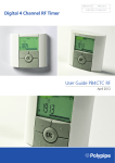
RF Digital programmable Thermostatic Head
ANNEXES
GB
2-9
51-52
1
1
IMPORTANT!
Presentation
- This product should be installed preferably by a
qualified professional. Subject to observation of the
above terms, the manufacturer shall assume the liability
for the equipment as provided by legal stipulations.
- All instructions in this Installation & Operation manual
should be observed when working with the controller.
Failures due to improper installation, improper use or
poor maintenance are voiding manufacturer liability.
- Any attempt to repair voids the responsibility and the
obligation to guarantee and replacement from the
manufacturer.
Display
LCD with white backlight
Angled for better viewing
APPLICATION
- The thermostatic heads BT-TH02 RF are developed to
control and manage many types of Hydraulic Heaters:
M30 x 1.5, M28 x 1.5, Watts TRV
5 Keys
- The controllers have been designed for use in
residential rooms, office spaces and industrial facilities.
Verify that the installation complies with existing
regulations before operation to ensure proper use of the
installation.
Electronic programmable thermostatic head with LCD
display, specially designed to control different types of
hydraulic heaters.
It will be your best partner to optimize your energy
consumption and increase your comfort.
Table of content
- Modern design.
- Stand alone or Wireless Bidirectional communication
868.3 MHz with Central Unit BT-CT02 RF compatibility.
- “Easy program creation” function.
- Weekly programmable by step of 30min.
- Temporary override function.
- Anti-freeze function.
- Adaptive PID regulation for better comfort and energy
saving
- EEPROM non volatile memory.
- 2 AA batteries (LR6)
- 2 parameter menus (User and Installer)
- 2 types of adapters to be mounted on hydraulic heaters:
M30 x 1.5
M28 x 1.5
Watts TRV valve
1
1.1
1.2
2
2.1
2.2
2.3
3
3.1
3.2
3.2.1
3.2.2
3.2.3
3.2.4
3.2.5
3.2.6
3.2.7
3.2.8
Presentation ..................................................... 2
Keyboard.......................................................... 2
Display ............................................................. 3
First Installation ................................................ 3
Batteries installation ......................................... 3
Time and Date adjustment ............................... 3
Thermostatic head installation ......................... 3
Stand-alone version ......................................... 4
Starting............................................................. 4
Working modes definition ................................. 4
Manual mode Comfort .................................... 4
Manual mode, Reduced .................................. 4
Manual mode, Anti-Freeze .............................. 4
OFF mode ...................................................... 4
Automatic mode .............................................. 4
Program mode ................................................ 4
Timer/Booster mode ....................................... 6
Clock update mode ......................................... 6
4
4.1
4.2
4.3
5
5.1
5.2
5.3
6
7
8
9
In combination with Central Unit ...................... 6
Installation ........................................................ 6
Starting............................................................. 7
Working modes ................................................ 7
Special functions .............................................. 7
Keyboard lock Function ................................... 7
Open window function ..................................... 7
Valve exercise function .................................... 7
Parameters menu ............................................ 7
Technical characteristics .................................. 8
Dimensions ...................................................... 9
Troubleshooting & Solution .............................. 9
1.1
Keyboard
Navigations keys :
LEFT Key
(◄)
and
RIGHT Key
(►)
Setting keys :
MINUS Key
(-)
2
OK Key
( )
MORE Key
(+)
1.2
Display
Note: You can go back to the previous value by pressing
(◄)
You can go to the next value by pressing (►)
List order of the time and date adjustments (Time & day):
Time
1. Adjustment of the hours
2. Adjustment of the minutes
Date
3. Adjustment of the year
4. Adjustment of the month number (01 to 12)
5. Adjustment of the day number (01 to 31)
Then the blinking message Save appears, press ( ) to
validate the adjusted time and date.
You can always reach the time and date adjustments by
the clock update mode.
2.3
1:
2:
3:
Current day of the week.
Operating mode menus (active mode is framed).
Program number or parameter number if “ ” is
displayed.
4: Installation Parameter menu.
5: Key lock indicator.
6: AM or PM for 12h clock hour display.
7: °C or °F unit indicator.
8: Setting temperature or Clock value.
9: Heating demand indication.
10: Pictograms for program creation, program state in
normal operating mode.
11: Program of the current day. (current time bar blinks)
12: RF transmission logo.
13: Open window detection logo.
14: Temporary override function activated
(Timer/booster mode)
2
2.1
Thermostatic head installation
Motor Move Menu
Open completely the thermostatic head for an easy
installation
-Go in the Parameters Menu number 10 by pressing and
maintain the ( ) key for more than 5 seconds, and we
will see the following screen :
-Press the ( ) key to validate. You will see Open. Wait
the backlight extinction, the motor will perform the
completely open move (during the move Open blinks).
When the thermostatic head is in the completely open
state, Open stops blinking and backlight shines again.
You are ready to install the thermostatic head on your
heater.
First Installation
Batteries installation
1
- Open the battery
cover and insert the
2 AA Alkaline
supplied batteries
(or remove the
small protection
sticker if the
batteries are
already installed in
the compartment).
2
3
1. Heater head
2. Adaptor nut
3. Plastic brackets
4. Fixing Screws
4
- Close the battery cover.
2.2
STEP 1
STEP 2
Screw the Adaptor
nut on the heater
Fix the brackets on the
Adaptor nut and the
thermostatic head
Time and Date adjustment
Each time a value blinks, you can adjust it with the (-)
and (+) keys, once the value is chosen, validate it with
the ( ) key. The thermostatic head will jump
automatically to the next value.
3
-You can now press LEFT (◄) or RIGHT (►) key to
display the working mode choice menu.
Move the frame cursor on the desired working mode and
press ( ) key to enter in the operating mode you have
chosen.
STEP 3
STEP 4
Fix the 2 screws on
the brackets
Push the ( ) key to finish
(Clos)
3
Stand-alone version
3.1
3.2.1
Starting
Manual working mode, the comfort setting temperature
will be followed all the time.
By pressing LESS (-) or MORE (+) keys, the comfort
setting temperature starts to blink and can be adjusted.
The thermostatic head is now ready to work.
The default working mode will be automatic
standard built-in program “P1”.
Manual mode Comfort
with a
Monday to Friday (week)
3.2.2
19°C
17°C
7:00
9:00
17:00
Manual working mode, the reduced setting temperature
will be followed all the time.
By pressing LESS (-) or MORE (+) keys, the reduced
setting temperature starts to blink and can be adjusted.
23:00
Saturday & Sunday (week end)
19°C
17°C
3.2.3
8:00
Manual mode, Reduced
Manual mode, Anti-Freeze
23:00
Pressing LESS (-) or MORE (+) keys, the anti-freeze
setting temperature starts to blink and can be adjusted.
Note:
You can customise your program as you want, See the
next part “Working mode definition” chapter “Program”
for more explanations.
3.2.4
OFF mode
Be Careful: In this mode your installation can freeze.
Setting View
Program
Clock View
Program
Use this mode if you need to switch off your installation.
Only the Time is viewed during this mode.
To restart your installation, use the navigation keys
LEFT (◄) or RIGHT (►).
3.2.5
Current position (blink)
(comfort one)
In this mode the thermostatic head will follow the chosen
At any time, when the backlight is off, press any key
to light-up the backlight, and then press another time the
(OK) key to switch the view between the setting
temperature and the time values.
3.2
Automatic mode
program (Built-in P or customized U) according to the
actual time and the Comfort and Reduced setting
temperatures.
Working modes definition
3.2.6
Following your installation (Unit installed) your
thermostatic head will offer different possibilities.
Your thermostatic head has several working modes to
allow you to adjust your unit according to your life habits.
Program mode
Current day
Program used
(blink)
How to change the working mode?
Program of the day
-Press any keys to switch on the backlight.
4
When you enter in the Program mode, the first operation Now you are invited to adjust the hour of the first step of
is to choose the program number with LESS (-) or MORE the program with LESS (-) or MORE (+) keys,
(+) key.
You can choose between a built-in program P1 to P9 or a
user program U1 to U4.
If you choose a Built-in program P1 to P9, you can only
see and chose the program.
P1:
Morning, Evening & Weekend
P2:
Morning, Midday, Evening & Weekend
P3:
Day & Weekend
P4:
Evening & Weekend
P5:
Morning, Evening (Bathroom)
P6:
Morning, afternoon & Weekend
P7:
7H – 19H (Office)
P8:
8H – 19H & Saturday (Shop)
P9:
Weekend (Secondary house)
(See the Annexe parts to view a complete description of
the Built-in programs).
Press ( ) to validate and go to the following step.
- Use the navigation keys LEFT (◄) or RIGHT (►) to
change the program day displayed.
Now you are invited to choose the type of the next step of
the program (blinking icons), 2 choices will be possible
(pressing LESS (-) or MORE (+) keys ) :
- 1st choice is the leaving icon
, to add one step.
- Press the ( ) key to confirm your choice and come
back to the main screen (in
mode).
nd
- 2 choice is the sleep icon.
If you chose a user program U1 to U4, as above you can
choose the program, see it, and you can also customise
it.
Default setting:
U1, U2, U3, U4 = comfort temperature all the week.
(End of the day).
When the choice is made, press ( ) key to validate.
Then you can adjust the step hour with LESS (-) or
MORE (+) keys,
- Press (OK) key during 2 seconds to customise a user
program.
Symbols and explanation for program creation:
When step hour is set press ( ) to jump to the next step.
First step of the day ( Comfort temp. )
The wakeup hour need to be adjusted.
Middle step of the day ( Reduced temp.)
The leaving hour need to be adjusted
Middle step of the day ( Comfort temp. )
The comeback hour will need to be adjusted
You will be directly invited to adjust with LESS (-) or
MORE (+) keys the hour of the comeback step.
Last step of the day ( Reduced temp.)
The sleeping hour need to be adjusted
- The minimum program step is 30 minutes
- Each time a value or icon blinks you are invited to make
a choice with LESS (-) or MORE (+) keys.
Once the choice is made press the ( ) key to jump to the
following step.
Press ( ) to validate and go to the following step.
- The program creation will always start with the day
value 1 (Monday).
Once you are in the program change mode (after
pressing the (OK) key for more than 2 seconds), the
following display will appear:
You are again invited to choose the type of the next step
of the program (blinking icons), with 2 choices:
5
st
- 1 choice is the sleep icons .
- 2nd choice is the leaving icons,
the program during the day.
(End of the day)
If you want to stop the Timer/Booster function before the
to add another step to end, set the duration period to “no” with LESS (-) key.
When the choice is made, press ( ) to validate and you
can adjust the hour of this step with LESS (-) or MORE
(+) key,
3.2.8
Clock update mode
By pressing LESS (-) or MORE (+) keys, your are
allowed to update time values ( Hour – Minutes – Year –
Month – Day of the month ) and validate it by pressing
( ) key.
See section 2.2 “Time and Date adjustment”
Press ( ) to validate and finish the edition of the first day.
4
Now you can choose to copy the program day just
created to subsequent days.
4.1
In combination with Central Unit
Installation
If your thermostatic head works in combination with a RF
Central Unit, it will become a remote unit.
(OK) key
pressed
To configure your thermostatic head with the BT-CT02
RF (Central Unit):
- Press and maintain the ( ) key during 5s, then you are
in the Parameters Menu number 10. Press the RIGHT
key (►) to be in the RF pairing mode (User Menu
number 11).
Other key
pressed
Copy the current day to the following day by pressing the
( ) key. [on Tuesday on Wednesday... up to the last day
of the week (7 Sunday) ].
If you don’t want to copy the current day press another
key (LESS (-) or MORE (+) or LEFT (◄) or RIGHT (►)
key )and you will be invited to create a program for
Tuesday (repeat the previous method to build it.)
** To ease the installation, it will be better to have the
Central Unite near to the thermostatic head during the
configuration mode. (A minimal distance of > 1 meter
must be respected)
When you press ( ) key on the last day (7 Sunday) you
will be invited to save your program.
Then the message “SAVE” appears and blinks until
validation:
- Now put your Central Unit in RF pairing mode too.
(please refer to the Central Unit leaflet for this )
The Central Unit will now send the radio configuration
signal to the thermostatic head.
- After few seconds, the Central Unit and the thermostatic
head should exit by themselves the RF pairing mode,
this is the normal procedure to confirm a correct pairing.
- Now, you can check the RF distance and if RF signal is
strong enough, replace the Central Unit to its room.
Return to your room where the thermostatic head is
placed. Put your thermostatic head in Comfort mode
(setting temperature position 30°C), wait the backlight
extinction and 5 seconds more (RF antenna will blink
during RF communication on the LCD).
- Now return to the Central Unit to see the setting passes
through the RF and is also equal to 30°C in the Central
Unit.
Press ( ) key to save your program and return to AUTO
operating mode following your user program.
3.2.7
Timer/Booster mode
The Timer/Booster mode allows you to adjust, the
temperature and the duration for a special time.
This function can be used when you stay at home for
several days, or if you want to override the program for
some time (reception...).
If the RF signals were received correctly, adjust your
setting temperature as you like.
If the RF signals weren’t received correctly, check the
installation (Position, distance...) or restart the RF pairing
rules to be sure. You may have to use a Watts RF
repeater if you want to extend the RF range.
Please note that this is not possible to make a direct RF
pairing between the BT-TH02 RF and a BT RF
thermostat. If you want to use a BT RF thermostat in a
room, you should pair the RF thermostat to the Central
Unit BT-CT02 RF, then pair one or several BT-TH02 RF
to the Central Unit.
- You can first adjust, the desired setting temperature
with LESS (-) or MORE (+) key, press ( ) key to start the
function. (Default value 24°C ).
- In a second time, you can adjust the duration in hours
“h” if below 24h, then in day “d” with LESS (-) or MORE
(+), press ( ) key to validate. (Adjustable 1 Hour to 44
days).
The Timer/Booster logo will blink and the number of
hours /days left is displayed until the end of the period.
You can switch between Timer counter value and
temperature Timer value by pressing ( ) key.
6
4.2
- The “
Starting
- Repeat the same procedure to unlock the key board.
The thermostatic head is now ready to work with the
Central Unit. The default working mode will be the mode
imposed by the Central Unit.
5.2
In case of Automatic mode
, no program can be
changed from the thermostatic head, the program is
directly set inside the Central Unit (see Central Unit
leaflet). The following screens can be viewed:
Setting View
” logo will be displayed on the screen.
Open window function
Conditions of open window detection:
The thermostatic head detects an "Open window" if the
room temperature decreases by 5°C or more during a 30
minutes period (or less).
In this case, the thermostatic head follows 7.0°C setting.
The function remains active until the room temperature
increases or until any key is pressed.
Clock View
As an indicator of this function running, the logo
blink.
Return to normal mode:
-Room temperature increases again for more than 1°C.
-Press any key.
Note: the time will be also sent by the Central Unit, then
all your installation will be synchronized with the same
time.
Then the blinking logo
should disappear to indicate
the end of the detection and return to previous setting
temperature.
At any time, when the backlight is off, press any
key to light-up the backlight, and then press another time
the ( ) key to switch the view between the setting
temperature and the time values. The days are not
shown anymore as no programmation is available in the
thermostatic head. Programmation is only possible inside
the Central Unit.
Special cases:
- This function doesn't work if Thermostatic head is in
OFF / Antifreeze Mode
5.3
4.3
will
Valve exercise function
Working modes
With the Central Unit, the Clock update and program
modes are note available anymore as setting time values
and program values are directly configured in the Central
Unit.
This function is performed if the thermostatic head
doesn’t move during 2 weeks.
This function doesn’t work in OFF mode.
The following modes are available; refer to stand-alone
version chapters for more explanations
Timer/Booster mode
6
-
Parameters menu
Your thermostatic head has parameters menu, in order
to enter in this menu, press and maintain the ( ) key
during 5 seconds. Then parameters menu will appear
and first parameter screen will be displayed:
Manual mode, comfort
Automatic mode
The thermostatic head will follow the program selected
on the Central Unit.
-
Manual mode, reduced
-
Manual mode, Antifreeze
Now you can select a parameter which must be adjusted
with the navigation LEFT (◄) or RIGHT (►) keys, once
the parameter chosen, toggle the value with the ( ) key,
modify it with LESS (-) or MORE (+) and confirm your
adjustment with ( ) Key.
To leave the parameter menu, choose the parameter
« End » (menu number 21) and press ( ).
the anti-freeze temperature is set by the Central Unit
(see the leaflet of the Central Unit to change the antifreeze value of your installation)
-
5
5.1
OFF mode
Special functions
Keyboard lock Function
Use this function to prevent all change of your settings (In
a child room, public area…)
- To activate the Key lock function, press maintained the
both LESS (-) and MORE (+) keys.
7
N°
Default value & other possibilities
10
oooo Thermostatic head initialization
This menu is used for the first time you install
the thermostatic head on the heater.
It helps to completely open or close the
thermostatic head and need to be done once.
11
12
13
14
15
16
17
18
19
rF Radio configuration
Sends the radio link signal in order to assign
this RF Thermostatic head with a Central Unit.
You also need to set simultaneously the
Central Unit in radio configuration mode (see
receiver Central Unit leaflet)
dEG Unit of the temperatures displayed
°C Celsius
°F Fahrenheit
hour Selection of the Time clock display
24H (24:00)
12H (12:00 AM /PM)
dst: Daylight Summer time change Summer<>Winter
YES automatic change according to date.
no no daylight summer time automatic
change.
AirC: Calibration of the internal probe
The calibration must be done after 1 day
working with the same setting temperature in
accordance with the following description:
Put a thermometer in the room at 1.5M
distance from the heater and check the real
temperature in the room after 1 hour.
When you enter on the calibration parameter
“no” is displayed on the right to indicate no
calibration has made.
To enter the value shown on the thermometer,
use the LESS (-) or MORE (+) keys to enter
the real value. Then, press ( ) key to confirm.
The value will be stored in the internal
memory.
If you need to erase a calibration press LEFT
(◄) or RIGHT (►) keys during the change, the
old value will be erased and the message “no”
will be displayed.
ITCS Intelligent Temperature Control System
YES
no
This function will activate your installation in
advance (2 hours maximum) to assure the
desired temperature at the hour programmed
following your weekly program.
This automatic control system works in the
following way:
When you start your thermostatic head for the
first time, it will measure the time taken by
your heater to reach the set temperature. The
thermostatic head will re-measure this time at
each program change to compensate external
temperature change & influence. You can now
program your thermostatic head without the
need to adjust the temperature in advance
because it does automatically this for you.
Win Open window
YES
no
This function, if activated, will detect the room
temperature decreasing for more than 5°C and
will automatically put the setting to 7°C to save
energy. (see section 4.2 for more details)
Batt Battery level
Indicates the battery voltage value.
Soft Software version
Indicates the software version v X.X
20
21
7
Clr: Reset to Factory setting
Press and maintain (Ok) key during 2 seconds
to reset Set points temperatures and user
parameters in this menu to factory default
settings. User programs will also be resetted.
Pay attention:
Ensure that you have all necessary elements
to re-setup your installation before using this
function.
End: Exit the parameters menu
Press (OK) key to exit installation parameters
menu and return to normal operation.
Technical characteristics
Environmental:
Operating temperature:
Shipping and storage
temperature:
Electrical Protection
Installation Category
Temperature precision
Setting temperature range
Comfort, Reduced
Antifreeze
Timer/Booster
Regulation characteristics
Maximum stroke
Maximum strength
Differential pressure
Power Supply
Operating life
Radio Frequency
Software version
Compatible with
Norms and homologation:
Your thermostatic head
has been designed in
conformity with the
following standards or
other normative
documents:
8
0°C - 40°C
-10°C to +50°C
IP20
Class I
0.1°C
5°C to 30°C by 0,5°C step
7.0°C (adjustable)
5°C to 30°C
PID
3,5mm
70N
1.5Bar
2 AA 1.5V Alkaline
> 1 year
868.3 MHz, <10mW.
Showed in parameter
menu 19. v X.X
Central Unit BT-CT02 RF
R&TTE 1999/5/EC
EMC 2004/108/CE
RoHS 2011/65/EU
8
Dimensions
9
Troubleshooting & Solution
My Thermostatic Head doesn’t start
Batteries
Problem
- Check if the protection sticker on
the batteries is removed.
- Check the batteries orientation.
- Check the capacity of the
batteries
Batteries
The word Batt and backlight blink
level is too
- Replace the batteries.
less
My Thermostatic Head seems to work correctly but
the RF communication doesn’t work correctly
On the thermostatic head:
- check the good reception of RF
Output
signal.
- Check the batteries
- Contact your installer.
My Thermostatic Head seems to work correctly but
the temperature in the room was never in
accordance with the program.
- Check the Clock.
-The difference between Comfort &
Reduced temperature is too high?
- The step in the program is too
Program
short?
- Contact your installer, to check &
adjust the regulation parameters
with your heating system.
9
Annexes (Built-in Program description)
P4:
P1:
1
0 1 2 3 4 5 6 7 8 9 10 111213141516 17 1819 20212223
2
0 1 2 3 4 5 6 7 8 9 10 111213141516 17 1819 20212223
1
0 1 2 3 4 5 6 7 8 9 10 111213141516 17 1819 20212223
2
0 1 2 3 4 5 6 7 8 9 10 111213141516 17 1819 20212223
3
0 1 2 3 4 5 6 7 8 9 10 111213141516 17 1819 20212223 3 0 1 2 3 4 5 6 7 8 9 10 111213141516 17 1819 20212223
4
0 1 2 3 4 5 6 7 8 9 10 111213141516 17 1819 20212223 4 0 1 2 3 4 5 6 7 8 9 10 111213141516 17 1819 20212223
5
6
7
0 1 2 3 4 5 6 7 8 9 10 111213141516 17 1819 20212223 5 0 1 2 3 4 5 6 7 8 9 10 111213141516 17 1819 20212223
0 1 2 3 4 5 6 7 8 9 10 111213141516 17 1819 20212223 6 0 1 2 3 4 5 6 7 8 9 10 111213141516 17 1819 20212223
0 1 2 3 4 5 6 7 8 9 10 111213141516 17 1819 20212223 7 0 1 2 3 4 5 6 7 8 9 10 111213141516 17 1819 20212223
P2:
1
0 1 2 3 4 5 6 7 8 9 10 111213141516 17 1819 20212223
2
0 1 2 3 4 5 6 7 8 9 10 111213141516 17 1819 20212223
P5:
1
0 1 2 3 4 5 6 7 8 9 10 111213141516 17 1819 20212223
2
0 1 2 3 4 5 6 7 8 9 10 111213141516 17 1819 20212223
3
3
0 1 2 3 4 5 6 7 8 9 10 111213141516 17 1819 20212223
0 1 2 3 4 5 6 7 8 9 10 111213141516 17 1819 20212223
4
0 1 2 3 4 5 6 7 8 9 10 111213141516 17 1819 20212223 4 0 1 2 3 4 5 6 7 8 9 10 111213141516 17 1819 20212223
5
6
7
0 1 2 3 4 5 6 7 8 9 10 111213141516 17 1819 20212223 5 0 1 2 3 4 5 6 7 8 9 10 111213141516 17 1819 20212223
0 1 2 3 4 5 6 7 8 9 10 111213141516 17 1819 20212223 6 0 1 2 3 4 5 6 7 8 9 10 111213141516 17 1819 20212223
0 1 2 3 4 5 6 7 8 9 10 111213141516 17 1819 20212223
7
P3:
1
0 1 2 3 4 5 6 7 8 9 10 111213141516 17 1819 20212223
2
0 1 2 3 4 5 6 7 8 9 10 111213141516 17 1819 20212223
0 1 2 3 4 5 6 7 8 9 10 111213141516 17 1819 20212223
P6:
1
0 1 2 3 4 5 6 7 8 9 10 111213141516 17 1819 20212223
2
0 1 2 3 4 5 6 7 8 9 10 111213141516 17 1819 20212223
3
0 1 2 3 4 5 6 7 8 9 10 111213141516 17 1819 20212223 3 0 1 2 3 4 5 6 7 8 9 10 111213141516 17 1819 20212223
4
0 1 2 3 4 5 6 7 8 9 10 111213141516 17 1819 20212223 4 0 1 2 3 4 5 6 7 8 9 10 111213141516 17 1819 20212223
5
0 1 2 3 4 5 6 7 8 9 10 111213141516 17 1819 20212223 5 0 1 2 3 4 5 6 7 8 9 10 111213141516 17 1819 20212223
6
7
0 1 2 3 4 5 6 7 8 9 10 111213141516 17 1819 20212223 6 0 1 2 3 4 5 6 7 8 9 10 111213141516 17 1819 20212223
0 1 2 3 4 5 6 7 8 9 10 111213141516 17 1819 20212223 7 0 1 2 3 4 5 6 7 8 9 10 111213141516 17 1819 20212223
7
51
P7:
1
0 1 2 3 4 5 6 7 8 9 10 111213141516 17 1819 20212223
2
0 1 2 3 4 5 6 7 8 9 10 111213141516 17 1819 20212223
3
4
5
6
7
0 1 2 3 4 5 6 7 8 9 10 111213141516 17 1819 20212223
0 1 2 3 4 5 6 7 8 9 10 111213141516 17 1819 20212223
0 1 2 3 4 5 6 7 8 9 10 111213141516 17 1819 20212223
0 1 2 3 4 5 6 7 8 9 10 111213141516 17 1819 20212223
0 1 2 3 4 5 6 7 8 9 10 111213141516 17 1819 20212223
P8:
1
0 1 2 3 4 5 6 7 8 9 10 111213141516 17 1819 20212223
2
0 1 2 3 4 5 6 7 8 9 10 111213141516 17 1819 20212223
3
4
5
0 1 2 3 4 5 6 7 8 9 10 111213141516 17 1819 20212223
0 1 2 3 4 5 6 7 8 9 10 111213141516 17 1819 20212223
0 1 2 3 4 5 6 7 8 9 10 111213141516 17 1819 20212223
6 0 1 2 3 4 5 6 7 8 9 10 111213141516 17 1819 20212223
7
0 1 2 3 4 5 6 7 8 9 10 111213141516 17 1819 20212223
P9:
1
0 1 2 3 4 5 6 7 8 9 10 111213141516 17 1819 20212223
2
0 1 2 3 4 5 6 7 8 9 10 111213141516 17 1819 20212223
3
0 1 2 3 4 5 6 7 8 9 10 111213141516 17 1819 20212223
4
0 1 2 3 4 5 6 7 8 9 10 111213141516 17 1819 20212223
5
0 1 2 3 4 5 6 7 8 9 10 111213141516 17 1819 20212223
6
0 1 2 3 4 5 6 7 8 9 10 111213141516 17 1819 20212223
7
0 1 2 3 4 5 6 7 8 9 10 111213141516 17 1819 20212223
PPLIMW15217Aa
52