1
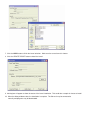
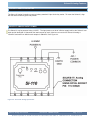
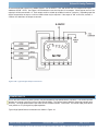
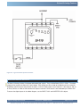
for REV 2.0 Models of
SI-110 & SI-210
Programs
in Ladder
Logic
SOLVES-IT! ANALOG
User’s Manual
PLC on a Chip Patent 7,299,099
REV .1
Smart Parts for Managing Automation
9778 Mt. Gilead Rd.
Fredericktown, OH 43019
Toll Free: 1-800-245-2327
Web: http://www.divelbiss.com
Email: [email protected]
2008003.1R2
!
IMPORTANT INFORMATION
REGARDING SOLVES-IT
CONTROLLER SHIPMENTS
!
To provide greater flexibility and reliability, Solves-It! Analog shipments are factory programmed without a KERNEL. You must install the kernel prior to being able to download EZ
LADDER programs.
To install a target kernel:
1. Connect the serial cable from the PC to the SI-110 / SI-210 (Programming Port).
2. Open the EZ LADDER Toolkit.
3. To load the kernel, you must configure the target and have at the minimum a one-rung program. For your convenience a program is pre-loaded on your computer (for EZ LADDER versions 1.0.4.4 and later). The file is named
GetStarted_SI-110_SI-210.dld and can be found in the Kernal Install Start Programs sub-directory where you installed
EZ LADDER.
OR
Otherwise, create your own using the Projects....Settings Menu,
select the “Solves-IT” target
and click the PROPERTIES button. Using the drop down menu, select the Solves-it model; either SI-110 or SI-210 and
click OK. You may also load a pre-saved ladder diagram that uses the same target. Verify the COM port is set correctly
and click OK to exit the Project Settings. See the EZ LADDER User’s Manual for details on configuring targets.
4. Click the
5. Click the
loaded.
(Monitor) button to change from the ‘Edit’ to ‘Monitor’ Mode.
(Connect) button to connect to the target. A dialog will appear automatically when no kernel is
6. Click the BROWSE button and select the target’s kernel (by partnumber) located by default at C:\Program Files\EZ
Ladder\Kernel\
The following is the kernel name and description:
File Name
Solves_It_SI_110.dat
Description
Kernel for Solves-It Analog
To be Used on (Partnumber)
SI-110, SI-210
7. Click the OPEN button to finish the kernel selection. Make sure the correct kernel is chosen.
8. Click the UPDATE TARGET button to install the kernel.
9. A dialog box will appear to show the status of the kernel installation. This could take a couple of minutes to install.
10. When the dialog windows close, the installation is complete. The Solves-It may be connected to
normally and programs may be downloaded.
Table of Contents
TABLE OF CONTENTS
Table of Contents
Package Contents
Page 1
Page 1
Getting Started
How to Use this Manual
Configuring the Solves-It! Analog Target in
EZ LADDER
Page 3
Solves-It! Analog Common Features
Getting to Know the Solves-It! Analog
Solves-It! Analog Mounting
Solves-It! Analog Input Power
Status LED
Programming Port
Dual Function I/O
Counter Inputs
Dedicated Digital Outputs
LED Indicators
Retentive Memory
Analog Inputs
Specifications
SI-210 Exclusive Features
Real Time Clock
Programmable Push Buttons
Programmable Display
Page 2
Page 2
Page
Page
Page
Page
Page
Page
Page
Page
Page
Page
Page
Page
Page
Page
Page
Page
Page
4
4
5
5
6
6
7
8
9
10
10
11
12
13
14
14
14
WARNING!
The SI-110 or SI-210, as with programmable controllers,
must not be used alone in applications which would be
hazardous to personnel in the event of failure of this
device. Precautions must be taken by the user to provide
mechanical and/or electrical safeguards external to this
device. This device is NOT APPROVED for domestic or
human medical use.
PACKAGE CONTENTS
Whats Included
Qty
1
6
Description
Part Number
Location
Controller
Commutating Diodes
SI-110 or SI-210
111-101012
In Box
In Box
Solves-It! Analog User’s Manual
Document #: 2008003.1R2.pdf
Page 1 of 14
Divelbiss Corporation 9778 Mt. Gilead Rd. Fredericktown, Ohio 43019 1-800-245-2327 www.divelbiss.com
GETTING STARTED
This section explains how to read this manual and understand the symbols.
HOW TO USE THIS MANUAL
In this manual, the following conventions are used to distinguish elements of text:
Denotes labeling, commands, and literal portions of
syntax that must appear exactly as shown.
BOLD
Used for variables and placeholders that represent the type of text
to be entered by the user.
italic
SMALL CAPS
Used to show key sequences or actual buttons, such as
the OK button.
OK,
where the user clicks
In addition, the following symbols appear periodically in the left margin to call the readers attention to specific details in
the text:
Warns the reader of a potential danger or hazard that is associated
with certain actions.
Appears when the text contains a tip that is especially helpful.
Indicates that the text contains information to which the reader
should pay particularly close attention.
All Specifications Subject to Change without Notice
Solves-It! Analog User’s Manual
Document #: 2008003.1R2.pdf
Page 2 of 14
Divelbiss Corporation 9778 Mt. Gilead Rd. Fredericktown, Ohio 43019 1-800-245-2327 www.divelbiss.com
Getting Started
CONFIGURING THE SOLVES-IT! TARGET IN EZ LADDER
Before you can program and use the Solves-It! Analog Controller, it must be configured as a target within EZ LADDER.
For help with installing or using EZ LADDER, please refer to the EZ LADDER User’s Manual.
In EZ LADDER, select PROJECT....SETTINGS. This will open the Project Settings Window. Select “Solves-It” for the target.
Click on PROPERTIES. The Solves-It dialog box will open. Using the drop down menu, select the correct Solves-It!
Analog model and click OK. Click OK again to close the Project Settings Window. Figure 1.1 show the Project Settings
Window and Solves-It Properties dialog box.
Figure 1.1
One you have configured the Solves-It! Analog target, EZ LADDER automatically creates variables for the Inputs,
Outputs, Programmable LEDs and Programmable Push Buttons (SI-210 only). For each variable, the appropriate I/O
address is automatically programmed for quick reference to use in the ladder program. Please note: The Solves-It!
Analog incorporates dual function I/O. This means that the first 4 digital I/O may be used as either inputs or outputs,
but not both. Only use the variable type (input or output) that is needed in your program.
The following variables are created automatically:
I/O Point
GPIO0
GPOI1
GPOI2
GPIO3
GPO4
GPO5
Input
Address
(Variable Name)
GPI0 (GPI0)
GPI1(GPI1)
GPI2 (GPI2)
GPI3 (GPI3)
-----
Output
Address
(Variable Name)
GPO0 (GPO0)
GPO1
GPO2
GPO3
GPO4
GPO5
Solves-It! Analog User’s Manual
(GPO1)
(GPO2)
(GPO3)
(GPO4)
(GPO5)
Description
Digital I/O 0
Digita lI/O 1
Digital I/O 2
Digital I/O 3 / CNTR
Digital Output 4
Digital Output 5
Variable
Name
I/O Address
AI0
AI1
AI2
AI0
AI1
Ai2
LED1
Document #: 2008003.1R2.pdf
LED1
Description
Programmable LED # 1 (I1)
Analog Input 1 - External
Analog Input 2 - Potentiometer 1
Analog Input 3 - Potentiometer 2
Page 3 of 14
Divelbiss Corporation 9778 Mt. Gilead Rd. Fredericktown, Ohio 43019 1-800-245-2327 www.divelbiss.com
SOLVES-IT! ANALOG
COMMON FEATURES
This section describes the hardware features and options including using EZ LADDER to operate the hardware
that are common for all Solves-It! Analog models.
GETTING TO KNOW THE SOLVES-IT! ANALOG
The Solves-It! Analog is connected to external devices via its mounting socket, Divelbiss part number 115-105328 (not
supplied), once it has been mounted. The Solves-It! Analog is programmed via its programming port using the programming cable SI-PGM.
Connector Pin out
Bottom View (Solves-It! Connector)
Pin
Pin
Pin
Pin
Pin
Pin
Pin
Pin
Pin
Pin
Pin
1
2
3
4
5
6
7
8
9
10
11
GPIO2
GPIO3 / High Speed Counter (CNTR)
GPO4
GPO5
AI0AI0+
Earth Gnd
- Power (Common)
+VDC Input Power
GPIO0
GPIO1
Figure 2.1 - Solves-It! Analog Connections
Solves-It! Analog User’s Manual
Document #: 2008003.1R2.pdf
Page 4 of 14
Divelbiss Corporation 9778 Mt. Gilead Rd. Fredericktown, Ohio 43019 1-800-245-2327 www.divelbiss.com
Solves-It! Analog Features
SOLVES-IT! ANALOG MOUNTING
The Solves-It! Analog Controller mounts to industry standard 11-pin Octal relay socket. To mount the Solves-It!, align
with the socket and firmly push into position.
SOLVES-IT! ANALOG INPUT POWER
The Solves-It! may be powered using 8-32VDC. The input power must be of sufficient supply to drive the Solves-It! controller and all the digital I/O (based on the load currents for each) Maximum current for the Solves-It! Analog is
150mADC and maximum load for each outputs is 500mADC. See Figure 2.2.
8-32VDC
Figure 2.2 - Solves-It! Analog Input Power
Solves-It! Analog User’s Manual
Document #: 2008003.1R2.pdf
Page 5 of 14
Divelbiss Corporation 9778 Mt. Gilead Rd. Fredericktown, Ohio 43019 1-800-245-2327 www.divelbiss.com
Solves-It! Analog Features
STATUS LED
The operating status of the Solves-It! Analog can be determined the by Status LED. When the Status LED is flashing at
a slow rate, approximately once per second, then there is no program executing. When the Status LED is flashing at a
fast rate, approximately 10 times per second, a program has been loaded and it is executing.
Should the Status LED not flash at all, first check the input power. If the input power is correct and there is still no Status
LED, contact Divelbiss Technical Services.
PROGRAMMING PORT
The Solves-It! Analog is programmed using its Programming Port. This RS232 serial port is only to be used for programming using Divelbiss’ EZ LADDER. The Programming Port defaults to 57600,N,8,1. This is not a general purpose
port. See Figure 2.3.
Figure 2.3 - Programming Port
Solves-It! Analog User’s Manual
Document #: 2008003.1R2.pdf
Page 6 of 14
Divelbiss Corporation 9778 Mt. Gilead Rd. Fredericktown, Ohio 43019 1-800-245-2327 www.divelbiss.com
Solves-It! Analog Features
DUAL FUNCTION I/O
The Solves-It! includes 4 on-board dual function I/O points. These points (GPIO0 - GPIO3) can be individually used as
either a digital input or a digital output. All digital inputs are optically isolated to promote noise immunity. When used as
an output, the input may be used to ‘monitor’ the output status.
GPIO3 may be used as a general purpose input, output or high speed counter; while GPIO0, GPIO1 & GPIO2 can only
be used as general purpose inputs or outputs. For information on using GPIO3 as a high speed counter input, refer the
COUNTER INPUTS Section, page 11 of this manual.
To access the digital inputs in the ladder diagram, use the DIRECT CONTACT and INVERTED CONTACT objects and
Input addresses GPI0 - GPI3. See Figure 2.4A connections to use dual function I/O as inputs. Inputs are true when
connected to +V.
8-32VDC
Figure 2.4A - Typical Digital Input Connections
Solves-It! Analog User’s Manual
Document #: 2008003.1R2.pdf
Page 7 of 14
Divelbiss Corporation 9778 Mt. Gilead Rd. Fredericktown, Ohio 43019 1-800-245-2327 www.divelbiss.com
Solves-It! Analog Features
To access the digital outputs in the ladder diagram, use the DIRECT COIL and INVERTED COIL objects and Output
addresses GPO0 - GPO3. See Figure 2.4B connections to use dual function I/O as outputs. When outputs are true, the
output pin will be sourced with +V. Each output can drive a load up to 500mA maximum (resistive). Depending upon the
device connected to an output, a minimum load resistor may be required. If the output is “ON” at all times, connect a
470Ω to 1KΩ load from the output to common.
8-32VDC
Figure 2.4B - Typical Digital Output Connections
COUNTER INPUTS
One of the dual function I/O points (GPIO3) may be utilized as a high speed counter (up count). The GPIO3 input will
operate as a counter up to the maximum input rate of 25KHz. The counter input is optically isolated to promote noise
immunity. The High speed counter input uses the EZ LADDER function: CNTRTMR. The counter input pulse device
must provide a +V input signal for proper operation.
Typical High Speed Counter connections are shown in Figure 2.6.
Solves-It! Analog User’s Manual
Document #: 2008003.1R2.pdf
Page 8 of 14
Divelbiss Corporation 9778 Mt. Gilead Rd. Fredericktown, Ohio 43019 1-800-245-2327 www.divelbiss.com
Solves-It! Analog Features
8-32VDC
Figure 2.5 - Typical Counter Input Connections
DEDICATED DIGITAL OUTPUTS
The Solves-It Analog includes 2 on-board dedicated digital outputs. They are identified as GPO4 - GPO5. The output
voltage will be equal to the Solves-It!’s input voltage. Each output can drive a load up to 500mA maximum (resistive).
Depending upon the device connected to an output, a minimum load resistor may be required. If the output is “ON” at
all times, connect a 470Ω to 1KΩ load from the output to common. GPO5 status is also indicated by the GPO5 LED.
To access the digital outputs in the ladder diagram, use the DIRECT COIL and INVERTED COIL objects.
Solves-It! Analog User’s Manual
Document #: 2008003.1R2.pdf
Page 9 of 14
Divelbiss Corporation 9778 Mt. Gilead Rd. Fredericktown, Ohio 43019 1-800-245-2327 www.divelbiss.com
Solves-It! Analog Features
8-32VDC
Figure 2.6 - Typical Digital Output Connections
LED INDICATORS
The Solves-It includes 1 on-board programmable LED indicators (labeled on the case as I1). This indicator may be used
to identify or indicate any condition in the ladder logic program. This LED indicator I/O address is LED1. See Figure 2.7.
To access the LED Indicators in the ladder diagram, use the DIRECT COIL and INVERTED COIL objects. This indicator
automatically has a variable labeled LED1.
GPO5 is an indicator LED for the GPO5 digital output and is directly connected to the output. The LED is ON when the
output is True or ON.
RETENTIVE MEMORY
The Solves-It Analog models with Real Time Clock (SI-210) support the use of Retentive Memory. The variables must be
‘declared’ retentive in the EZ LADDER program to operate properly.
Solves-It! Analog User’s Manual
Document #: 2008003.1R2.pdf
Page 10 of 14
Divelbiss Corporation 9778 Mt. Gilead Rd. Fredericktown, Ohio 43019 1-800-245-2327 www.divelbiss.com
Solves-It! Analog Features
Figure 2.7 - LED Indicators
ANALOG INPUTS
The Solves-It! Analog has three analog inputs. The first, AIO is an external analog input that will accept a differential
input signal of 0-10VDC or 0-20mADC with the addition of an external resistor. It is accessed in the EZ LADDER program by the variable AI0.
The other two analog inputs are internal to the Solves-It! Analog. They are connected to potentiometers that can be
adjusted through the top of the Solves-It!’s plastic housing. These analog inputs (AI1, AI2) simply provide potentiometer
adjustments for the use in any application for timer adjustments , etc.. To access them in the EZ LADDER program use
variables AI1 and AI2.
Each of the analog inputs will be represented using the variable as an integer number between 0 and 1023 (0 = 0VDC or
Potentiometer set to minimum; 1023 = 10VDC or Potentiometer set to maximum).
Figure 2.8 - Analog Input Potentiometers
Solves-It! Analog User’s Manual
Document #: 2008003.1R2.pdf
Page 11 of 14
Divelbiss Corporation 9778 Mt. Gilead Rd. Fredericktown, Ohio 43019 1-800-245-2327 www.divelbiss.com
Solves-It! Analog Features
SPECIFICATIONS
Processor:
Memory:
Serial Ports:
Digital I/O:
Real Time Clock*:
Counters:
Power Requirements:
Indicators:
Analog Inputs:
Display*:
Push Buttons*:
Operating Temp:
Program Language:
Dimensions:
Mounting:
Type:
PLC on a ChipTM
64K Flash
1 Programming Port (Max baud: 57.6K);
4 Sinking Inputs, rated 8-32VDC.
6 Sourcing SSR Outputs, rated 8-32VDC @ 500mADC Max. each. Output Voltage = Input Power
Time of Day, Day, Month, Year & Day of Week
1 Channel, Count Up. GPIO3 = 25KHz Max.
8-32VDC @ 150mADC Max (Excludes I/O)
1 Programmable LED Indicator, 1 Status LED Indicator, 1 Output LED Indicator (GPO5)
1 0-10VDC External, 2 Internal Potentiometer
4 Digit, 7 Segment Programmable LED Display
2 Programmable Push Buttons
-40-65º C
Ladder Logic using Divelbiss EZ LADDER
2.4” Wide x 1.75” Length x 4.2” Tall.
Plugs into Industry standard 11-pin Octal Relay Socket
Plastic Housing
* Indicates features only available on model SI-210.
Solves-It! Analog User’s Manual
Document #: 2008003.1R2.pdf
Page 12 of 14
Divelbiss Corporation 9778 Mt. Gilead Rd. Fredericktown, Ohio 43019 1-800-245-2327 www.divelbiss.com
SI-210 EXCLUSIVE
FEATURES
This section describes the hardware features and options including using EZ LADDER to operate the hardware
that is specific to the Solves-It! Model 210 (SI-210).
SI-200 Exclusive Features
REAL TIME CLOCK
The SI-210 includes a Real Time Clock. The real time clock (after being set) provides the Month, Day, Day of the
Week, Year, Hour, Minute and Second. The real time clock maintains time when power is lost via lithium battery. The
Real Time Clock may be accessed using the EZ LADDER functions: GETDATE, GETTIME, SETTIME, SETDATE.
PROGRAMMABLE PUSH BUTTONS
The SI-210 includes two programmable push buttons (labeled on the case as PB1and PB2). These push buttons are
I/O addressed using PB1 and PB2 in EZ LADDER.
To access the push buttons in the ladder diagram, use the DIRECT CONTACT and INVERTED CONTACT objects.
These push buttons are automatically have variables labeled PB1, PB2. See Figure 3.1.
PROGRAMMABLE DISPLAY
The SI-210 includes a programmable 4 digit, seven-segment display. This display may be used to display setpoints,
actual timers and more. See Figure 3.1.
To access the display in EZ LADDER, use the SI_DISP and SI_CLRDISP
Figure 3.1 - Push Buttons and Display
Solves-It! Analog User’s Manual
Document #: 2008003.1R2.pdf
Page 14 of 14
Divelbiss Corporation 9778 Mt. Gilead Rd. Fredericktown, Ohio 43019 1-800-245-2327 www.divelbiss.com
Limited Warranty
Divelbiss Corporation warrants equipment will be free from defects in material and workmanship for
a period of one (1) year from the date of the Divelbiss invoice that the equipment was furnished.
Divelbiss Corporation will not be liable for any design furnished by Buyer and incorporated into the
equipment.
In no event shall Divelbiss Corporation be liable for anticipated profits, consequential damages or
loss of use of equipment or of any installation into which the equipment covered by this order may
be put.
Divelbiss Corporation shall not be liable or responsible for any loss, injury, or damage resulting
directly or indirectly from the use of software and/or programming in any way associated with the
equipment of this order.
Obligations are to be limited to the repair or replacement at the Divelbiss Corporation plant,
Fredericktown, Ohio, upon return of the part or component in question, prepaid by Buyer. The return
freight charges to be paid by Divelbiss. The part or component is only to be returned to Divelbiss
with a Returned Material Authorization number issued by the Divelbiss Service Department. Any
warranty service (consisting of time, travel, and expenses related to such services) performed other
than at Divelbiss Corporation plant, shall be at Buyer's expense.
Warranty of repaired or replacment products will be limited to ninety (90) days or the remainder of
the original warranty whichever is greater.
Warranty is available only if Divelbiss Corporation is promptly notified in writing upon discovery of
any alleged defect and examination of the subject product discloses, to Divelbiss satisfaction, that
any defect has not been caused by misuse; neglect; improper installation; improper operation;
improper maintenance, repair, or alteration; accidents; or unusual deterioration or degradation of the
equipment or parts thereof due to physical environment or due to electrical or electromagnetic noise
environment.
This warranty is in lieu of all other warranties, expressed, implied, or statutory, including warranties
of merchantability or fitness for a specific purpose.