1
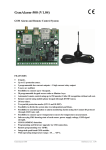
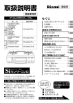
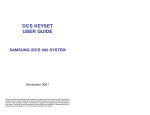
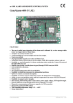
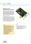
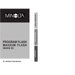
GSM alarm system
1.
__
GsmAlarm-400 (401) mini
GSM alarm system
GsmAlarm-400 (401) mini
SMS. After at least one user picks up, the system stops calling and sending SMSs. In order to
get a message showing state of all the zones, send the system a SMS with the password and
word ZONES? Then GsmAlarm sends a SMS, showing state of the controlled zones, to that
user. In order to get information about power source and communication quality, send a
message, containing password and word PRINFO.
GENERAL DESCRIPTION
GsmAlarm-400 is a 4-zone GSM alarm system and and may be customized for premises
protection. GsmAlarm-400NK is operable along with NOKIA-5110 or NOKIA-6110 cellular
phone units; GsmAlarm-400SI is operable along with SIEMENS C35i, M35i, S35, ME45,
M50, MT50 cellular phone units; GsmAlarm-400ER is operable along with ERICSSON T10s,
T18s, T28s cellular phone units.
GsmAlarm-400 has an integrated AC-DC converter; it may charge a standard battery with
capacity 7Ah. In the case of alarm, the unit starts a siren and may call or send SMSs to five
users. The SMS shows the user the name of the violated zone as well as the number of times the
sensor was triggered.
__
3.
INSTALLATION
GSM PHONE
System activation/deactivation is available remotely and is cost free. The system is activated
with a brief call to the GsmAlarm phone. In order to deactivate the system, call and wait for
some time: after 3-4 tones the system is deactivated. GsmAlarm is controllable from the user's
phone only. If unknown number is calling, the call is immediately interrupted and the user gets
a SMS showing the caller's number.
SIGNAL
Z1
Z2
Z3
Z4
MODE
ALARM
GsmAlarm - 400
SMS also shows power failure of the main source (220V). In this case the system is powered
from the reserve battery. SMS is also sent after the power supply is restored.
The system may be programmed remotely, by sending to GsmAlarm a SMS with relevant
contents and password.
2.
USER'S MANUAL
GND Z1
Z2
Z3
Z4
Z5
GND
C1 BELL AUX BATT
GND
AC
16-18V
User can activate/deactivate the system in the following two ways:
_______________________________________________________________________________
1
R3
2,2K
R4
2,2K
D3
D4
LED1
R5
2,2K
+
R2
2,2K
R6
2,2K
+
D2
-
2) Remotely, using own cellular phone.
In order to activate the system, user must call the GsmAlarm number and, after hearing the first
tone, cancel the call. No activation delay time is counted in this case, after the system is
activated, the user gets a short confirming call. Confirming call needs no cancellation, it is
cancelled automatically.
The alarm may be deactivated by calling the GsmAlarm number and waiting for the system
cancels the call (3-4 tones). If after remote deactivation neither of the sensors are triggered
within one minute, the system automatically enters “armed” mode and the user, who
deactivated the system, gets a brief confirming call.
In order to check operation of the alarm, call briefly the GsmAlarm number. If it is operative,
the calling user gets a short confirming call.
In the alarm case, depending on the programmed parameters of the triggered zone, all the users
in a sequence are called or sent SMSs, showing the triggered zone name and number of triggers.
User may pick up and listen what is going on in the premises, or cancel the call and wait for
D1
-
R1
2,2K
1) Using the ON/OFF switch.
In this case, after the switch is switched ON, the activation delay time is started to count down
(MODE indicator is blinking). If after expiration of the given time neither zone is activated, the
system enters “armed” mode, user ALRNR1 gets a short confirming call and MODE indicator
starts blinking at a reduced frequency. Confirming call needs no cancellation, it is cancelled
automatically. If after the delay period no confirming call is received and MODE indicator is
continuously on, it means that some of the zones is active (open window, door etc.).
Alarm may be deactivated by switching the switch OFF. If the system is deactivated and the 24hour zone is triggered, the siren and the call may be cancelled by switching the switch ON and
immediately OFF.
AC
~16...18V
BATTERY
12V
SIREN
S1
ON/OFF
Fig.1.
GsmAlarm connection diagram
3.1
CONTROLLED ZONE INPUTS (Z1-Z5)
Controlled zone inputs Z1-Z4 are used to connect sensors. All the inputs are analogue, i.e.
micro controller is measuring voltage in each input, thus, in the case of short circuit or brake of
the controlled circuit, the system enters the alarm mode (siren is on, user is called or sent a
SMS). Each zone input must be loaded with 2.2k resistors, connecting them to the sensors,
located farthest. The connection diagram shows two sensor connection options.
D1 and D2 are standard sensors used in the protection systems with closed contacts at rest (e.g.
magnetic contacts of windows, doors). When the sensor is triggered, the contacts become open
and the system enters danger mode.
D3 and D4 are standard sensors used in the protection systems with open contacts at rest (e.g.
movement or fire sensors). When the sensor is triggered, the contacts close and the system
_______________________________________________________________________________
2
GSM alarm system
__
GsmAlarm-400 (401) mini
GSM alarm system
•
enters alarm mode: after the delay period, audio siren is on and the system calls or sends the
user SMS.
OUTPUT BELL
The BELL output is used to connect audio siren. Commutated current may reach 2A. When
active, BELL is connected to GND (ground) wire.
3.3
•
OUTPUT C1
The programmable output C1 may be used to connect external system mode indicator LED1.
Maximum commutated current in this output is 200mA.
3.4
3.5
CONTACT BATT
The BATT contact is to be connected to positive terminal of reserve battery.
3.6
CONTACTS AC
The AC input is used to connect secondary winding of power supply transformer (16-18V AC).
3.7
LED INDICATORS
The LEDs (fig. 1) enable instant adjustment of the system at installation and fault localization.
•
SIGNAL: GSM module operation mode indication. Possible states:
Off - system is off, there is no power supply.
Continuously On - GSM module is effective, but there is no network registration.
Possible causes: SIM card PIN code request is not off, there is no antenna connected or
communication quality is poor.
Blinks every 2-3 seconds. GSM module is active, communication is present, and all is OK
•
MODE and LED1: system mode indicators.
ALARM: alarm mode indicator.
Blinks at a permament rate - system is in alarm state, call is made or SMS sent.
Blinks twice every 2-3 seconds - SMS center (SMSNR) or ALRNR1 number has not been
programmed. In order GsmAlarm could send SMS and make calls, these numbers need to
be programmed!
OUTPUT AUX
The AUX output is used to supply power to external devices and is short-circuit-protected. This
output has voltage +12...+13.7V. Maximum load current is 1A.
GsmAlarm-400 (401) mini
Off - system is off. Possible causes: there is no supply voltage or some damage is present.
Continuously On - system is on, but it is disarmed.
Blinks every 2-3 seconds. System is operating in “armed” mode, there is no alarm.
Blinks twice every 2-3seconds. System is operating in “armed” mode, but mobile
communication devices are out of operation. If zone is triggered in this state, only siren
will be on.
Blinks rapidly (several times per second). System is in alarm state, siren is active, call is
made or SMS is sent. If SMS is sent, indicator blinks a little bit slower (about twice a
second).
Blinks very rapidly (10-20 times a second): SMS instruction receipt confirmation.
Input Z5 (S1 switch) is used to activate/deactivate the system,. If S1 contacts are open, the
system is off - no zones are checked (except when zone operates in 24-hour mode). If contacts
of S1 are closed, the system is active - all the zones are checked, in the case of alarm siren is on
and the system calls or sends the user SMS.
3.2
__
4.
GETTING READY FOR WORK
Before switching the power source on, GsmAlarm-400 inputs Z1-Z5 need to be loaded with
2.2k resistors, switch S1 must be OFF. Insert SIM card into mobile phone with its PIN code
request OFF, connect phone to GsmAlarm-400. After switching power source on, wait for
SIGNAL indicator starts blinking periodically and MODE (LED1) indicator is on
continuously. If SIGNAL indicator is on continuously, check if the SIM card PIN code request
has been switched off. Slowly blinking ALARM indicator shows that SMS center (SMSNR) or
(and) ALRNR1 number has not been programmed. Program them in accordance with paragraph
5.1. If both numbers have been programmed, ALARM indicator is OFF.
ALRNR1 number needs to be programmed. This number is used by GsmAlarm to send SMSs
at main power failure or if a call from unknown number is received. After the system is
switched on with S1 switch, the control call is addressed to the first user. The rest four user
numbers are not required. Sequence is also not required, e.g. you can program ALRNR1,
ALRNR4 and ALRNR5.
If needed, the zone and system parameters shall be programmed (see par.5.4). Upon completion
of programming, it is recommended to change SMS password (see par. 5.2). After you connect
reserve battery and check for Z1-Z4 control LEDs are off, activate the system with S1, wait for
confirming call at ALRNR1 number. To check if the system sends SMSs, switch off the main
power source. After 20 seconds user ALRNR1 is sent a SMS. If not, check SMS central number
for correct programming.
Note. In case of main power failure or restoration, SMS is sent only in “armed” mode and only
to ALRNR1 user.
Z1 – Z4: zone status indicators.
Off - zone is not triggered.
Continuously On - zone is triggered or load resistor is broken.
_______________________________________________________________________________
3
_______________________________________________________________________________
4
GSM alarm system
__
GsmAlarm-400 (401) mini
GSM alarm system
5.3
__
GsmAlarm-400 (401) mini
5.
PROGRAMMING
5.1
SMS CENTER AND USER NUMBER PROGRAMMING
In order to get a SMS about state of the system and protected zones, send the following SMS:
In order to program SMS central and user numbers, sent to GsmAlarm-400 SMS with the
following contents:
AAAAAAAA ZONES?
AAAAAAAA SMSNR:0123456789 ALRNR1:0123456789 ALRNR2:0123456789
ALRNR3:0123456789 ALRNR4:0123456789 ALRNR5:0123456789
INFORMATION SMSs
In order to get a SMS with programmed numbers and password, send GsmAlarm the following
SMS:
AAAAAAAA NRINFO
AAAAAAAA - eight-character SMS password, obligatory in the beginning of each SMS.
Manufacturer has programmed the following password: AAAAAAAA. User may change the
password as he wants (see par.5.2).
In order to get a SMS with information about GSM signal strength and power supply voltage,
send GsmAlarm the following SMS:
SMSNR - SMS center number.
AAAAAAAA PRINFO
ALRNR1 - ALRNR5 - user numbers. GsmAlarm-400 may be called exclusively from these
numbers. All the other calls are ignored and immediately cancelled.
In order to get a SMS with programmed parameters and names of protected zones, send
GsmAlarm the following SMS:
If programming is performed correctly, user gets a SMS with newly programmed numbers.
AAAAAAAA SPARAM
In order to delete unnecessary number, send the following SMS:
AAAAAAAA ALRNR2:N
Number ALRNR2 is deleted; user gets a SMS with programmed numbers. In order to alter a
number, no additional instruction to delete the old number is necessary.
5.2
SMS PASSWORD CHANGE
In order to change manufacturer's SMS password, send GsmAlarm the following SMS:
AAAAAAAA PASSW:ABCDefgh
AAAAAAAA is the old password.
PASSW: - password changing instruction.
ABCDefgh - new SMS password. It must contain 8 characters.
If programming instruction is performed correctly, user gets a SMS with newly programmed
password.
_______________________________________________________________________________
5
_______________________________________________________________________________
6
GSM alarm system
5.4
__
GsmAlarm-400 (401) mini
GSM alarm system
__
GsmAlarm-400 (401) mini
PROGRAMMING OF SYSTEM PARAMETERS AND ZONE NAMES
All GsmAlarm-400 zone input operation modes, delay times and names may be programmed
with a single SMS. First of all it is advisable to get a SMS with already programmed
parameters. In order to do this, send GsmAlarm the following SMS:
In order to change parameters or names, send GsmAlarm a special SMS, containing the parameters to
be changed, e.g.:
AAAAAAAA Z1:M10T20 Name1, Z2:M20, Z3:name3, Z4:T10 Name4, PR:C01T40S01
AAAAAAAA SPARAM
AAAAAAAA - 8-character password.
Send this SMS from any GSM subscriber, not necessarily from the user. The only condition is
that you must know the correct password. SMS central number must have been programmed
also (see par. 5.1), otherwise GsmAlarm is unable to send a SMS.
Z1: - parameter change instruction for relevant zone (colon is obligatory).
M10 - zone operation mode instruction, 10 - 2-digit number XY (X=1, Y=0), specifying zone mode
(see fig. 2).
T20 - zone delay time in seconds, in this case it is 20 seconds. Possible values: 00...99. Number must
have 2 digits. E.g., for the delay time was 5 seconds, state T05 (not T5). The delay time is ignored,
when zone is in a 24-hour mode.
Name1 - name of zone 1. It is 16 digits long at a maximum.
PR:C01T40S01 - system parameter changing instruction (colon is obligatory)
GsmAlarm-400 sends SMS to the sender's address, showing all zone parameters and names.
SMS with manufacturer's parameters looks like the following:
Z1:M70T20 Door, Z2:M70T20 Windows, Z3:M70T00 Movement, Z4:M71T00 Fire,
Z5:M02T00 ON-OFF, PR:C12T20S02
Z1
- zone number;
M40 - zone operation mode, parameter M (see fig.2);
T20 - zone delay time after triggering (seconds);
Door - zone name, showed in the SMS after triggering.
PR:C12T20S02
PR - system parameters
C12: the first digit (1) shows whether SMS is to be sent if GsmAlarm is called from unknown
number. In this case SMS will be sent. The second digit (2) shows number of the calls to the
user (users) in case of alarm. In this case system will call twice (on condition that X value
equals 2, 4 or 7 in fig. 2).
T20: shows how many seconds the system will wait before checking the zones after “arming”.
This time is the same for all the zones.
C01 - the first digit (0 in this case) shows system response to stranger’s call. Possible
values are 0 or 1. If it is 1, after a stranger calls the system, the system cancels the call and
sends the first user a SMS, showing caller's number. If it is 0, after a stranger calls the
system, the system cancels the call and sends no SMS.
Second digit (1 in this case) is a number of calls in the alarm case. Possible values are 1, 2
or 3. In order to change only one of these parameters, SMS must include also the other
parameter, i.e. number after C must have two digits.
T40 - delay time after system activation. In this case zones are not checked 40 seconds
after switching on. Possible values are 00...99. The delay time is ignored, when zone is in
a 24-hour mode.
S01 - siren on time in alarm case (in minutes). Possible values are 01...99.
In the given example the following parameters are changed: zone 1 operation mode, delay time and
name, zone 2 - only operation mode (M20), zone 3 - only name, zone 4 - delay time (10 seconds),
SMS sending condition after stranger's call and number of calls in alarm case (01), delay time after
switching on (40 seconds) and siren on time (1 minute).
S02: - siren ON time in alarm case (minutes).
IMPORTANT !
Alarm state after zone activation
Zone mode
M
Only information zone
Only siren is on
X
0
1
Y
0
1
Only calling
2
2
Only SMS is sent
Call is made and SMS is sent
Siren is on, call is made
Siren is on, SMS is sent
Siren is on, call is made, SMS is sent
3
4
5
6
7
3
-
Zone with delay
24-hour zone, siren is on
continuously
24-hour zone, siren is on with
interruptions (fire sensor)
ON/OFF zone
-
Fig.2
Zone operation mode, parameter M
_______________________________________________________________________________
7
a) no space character must be inserted after the colon;
b) if not only name is changed (in this case A1 and Z4), space character must be inserted between the
two-digit number and name;
c) comma must be inserted after the last changed zone parameter.
ON/OFF zone is used for alarm arming/disarming. When zone is non-active, the system is off, no
zone sensor signals are responded to (except when zone is in 24-hour operation mode).
When ON/OFF is active (short or broken circuit), system is in the “armed” mode. After the protected
zone is activated, the alarm responds in accordance with the table, given in fig.2.
_______________________________________________________________________________
8
GSM alarm system
5.5
__
GsmAlarm-400 (401) mini
MANUFACTURER'S (DEFAULT) PARAMETERS
GSM alarm system
6.
__
GsmAlarm-400 (401) mini
TECHNICAL CHARACTERISTICS
Password: AAAAAAAA
POWER SUPPLY
There are neither SMS center nor user numbers programmed.
AC voltage in the secondary winding of power transformer (input
“AC”)
Minimum current of the secondary winding of power transformer
Reserve battery type
Reserve battery operation voltage
Reserve battery maximum capacity
Reserve battery charging current
Z1: zone with delay, delay time is 20 seconds (M70T20), name - Door;
Z2: zone with delay, delay time is 0 seconds (M70T00), name - Windows;
Z3: zone with delay, delay time is 0 seconds (M70T00), name - Movement;
Z4: 24-hour zone, siren is on with breaks (M72T00), name - Fire;
Z5: ON/OFF zone (M03T00).
PR:C12T20S02 - in case stranger's call incomes, user is sent a SMS; number of the calls in alarm
case is 2 (C12), delay after switching on is 20 seconds (T20), siren on time is 2 minutes (S02).
In order to reset all the system parameters into the default ones, do the following:
•
•
•
•
•
switch off both power source and reserve battery;
insert RESET jumper;
switch on the power source and wait till SIGNAL indicator is on;
switch off power source;
take off RESET jumper.
~ 16 ÷18V
600 mA
PB-acid
12V
7 Ah
300 ÷500 mA
AUXILIARY DEVICE FEEDING OUTPUT“AUX “
Maximum current
Short circuit protection triggering current
1A
1,35 A
SIREN OUTPUT “BELL”
Maximum current
Output active (siren is on)
2A
Connected to
GND
Open contact
Output non-active (siren is off)
OUTPUT “C1”
Maximum current
Output active (siren is on)
200 mA
Connected to
GND
Open contact
Output non-active (siren is off)
INPUTS “Z1”-“Z5”
2,2 kΩ, ±10 %
3,5 V
1V
Load resistance
Upper triggering limit
Lower triggering limit
© ELEKTRONINĖS TECHNOLOGIJOS, 2006
http://www.eltech.lt
_______________________________________________________________________________
9
_______________________________________________________________________________
10