1
Interfaces
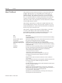
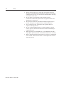
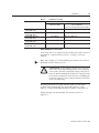
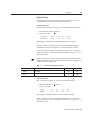
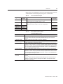
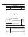
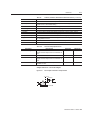
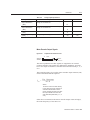
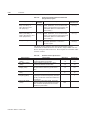
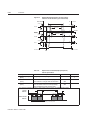
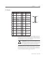
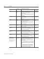
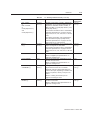
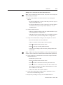
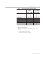
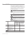
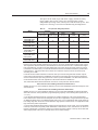
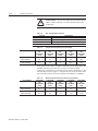
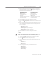
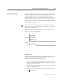
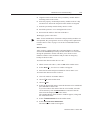
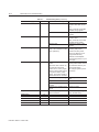
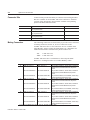
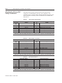
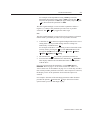
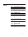
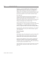
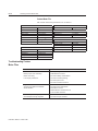
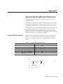
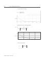
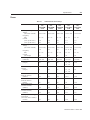
Table 6.16:
Specification
ANALOG 1
Output Resolution
(Bits)
ANALOG 2
Output Resolution
(Bits)
Output Current
(mA)
Output Signal Range
(Volts)
6-17
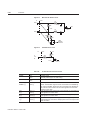
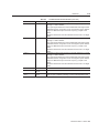
Analog Output Specifications
Description
Number of units that the ANALOG1 output
voltage is converted into.
Minimum
Maximum
12
Number of units that the ANALOG2 output
voltage is converted into.
8
Allowable current draw of the load
+2
-2
Voltage range of the signal
-10
+10
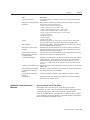
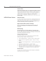
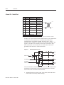
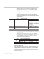
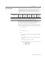
Motor Encoder Output Signals
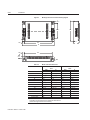
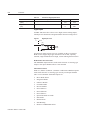
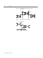
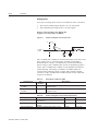
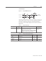
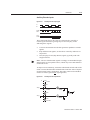
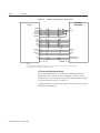
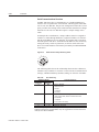
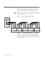
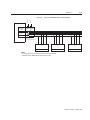
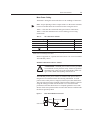
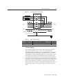
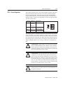
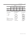
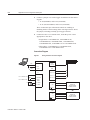
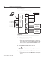
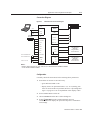
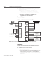
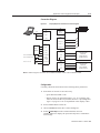
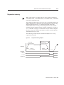
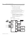
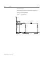
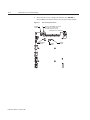
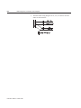
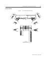
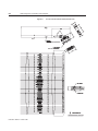
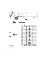
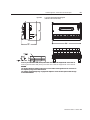
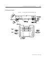
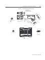
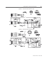
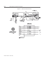
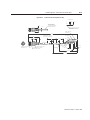
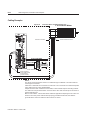
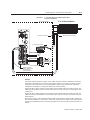
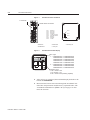
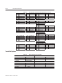
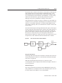
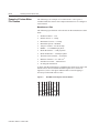
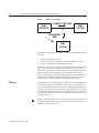
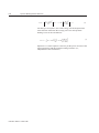
Figure 6.20
Output Encoder Interface Circuit
Intro
J1
Drive
AMOUTAMOUT+
AMOUT
AM26C31 or AM26LS31
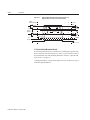
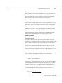
The motor quadrature encoder signals are supplied to an external
position controller. The signals are differential, quadrature, and TTL
level. The output resolution is selectable and can be divided by 1, 2, 4
or 8.
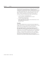
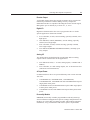
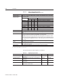
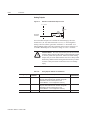
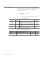
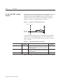
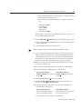
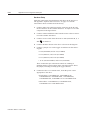
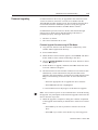
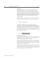
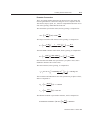
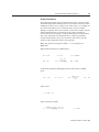
The signal frequency (fout) of the motor encoder output in Hertz (Hz)
can be calculated with the equation:
Vm ⋅ linecount
f out = --------------------------------------60 ⋅ N
where:
Vm is the motor encoder velocity
in rpm linecount is the number of
encoder lines/revolution of the
motor mounted encoder, and N is
the output divider from the software selected parameter (1, 2, 4
or 8).
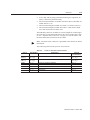
If the device connected to the motor encoder output counts all edges,
the count frequency is four times fout.
Publication 1398-5.0 – October 1998