1
Allen-Bradley
ULTRA
200 Series
Digital Servo
Drives
User
Manual
Important User
Information
Because of the variety of uses for the products described in this
publication, those responsible for the application and use of this
control equipment must satisfy themselves that all necessary steps
have been taken to assure that each application and use meets all
performance and safety requirements, including any applicable laws,
regulations, codes and standards.
The illustrations, charts, sample programs and layout examples shown
in this guide are intended solely for purposes of example. Since there
are many variables and requirements associated with any particular
installation, Allen-Bradley does not assume responsibility or liability
(to include intellectual property liability) for actual use based upon the
examples shown in this publication.
Allen-Bradley publication SGI-1.1, Safety Guidelines for the
Application, Installation, and Maintenance of Solid-State Control
(available from your local Allen-Bradley office), describes some
important differences between solid-state equipment and
electromechanical devices that should be taken into consideration
when applying products such as those described in this publication.
Reproduction of the contents of this copyrighted publication, in whole
or in part, without written permission of Allen-Bradley Company,
Inc., is prohibited.
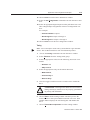
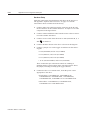
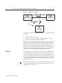
Throughout this manual we use notes to make you aware of safety
considerations. For example:
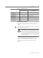
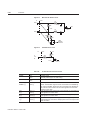
Intro
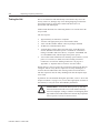
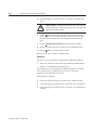
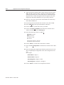
!
ATTENTION: This symbol identifies information about
practices or circumstances that can lead to personal injury
or death, property damage or economic loss.
Attention statements help you to:
●
●
●
identify a hazard
avoid the hazard
recognize the consequences
Note: This symbol identifies information that is critical for successful
application and understanding of the product.
Mathcad is a registered trademark of MathSoft, Inc.
Microsoft, MS-DOS and Windows are trademarks of Microsoft Corporation.
UL and cUL are registered trademarks of Underwriters Laboratories.
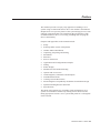
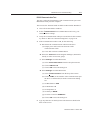
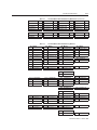
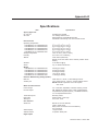
Table of Contents
IntroTable of Contents
Table of Contents
Intro-1
List of Figures
Intro-7
List of Tables
Intro-11
Preface
Intro-15
About This Manual . . . . . . . . . . . . . . . . . .
Additional Instructions and Manuals . . . . . . . .
Host Commands and ULTRA Master . . . . . .
TouchPad . . . . . . . . . . . . . . . . . . . . . .
Symbols and Conventions . . . . . . . . . . . . . .
Typographical and Wording Conventions . . . .
Graphical Symbols and Warning Classifications
Pictorial Index . . . . . . . . . . . . . . . . . . . . .
Chapter 1
. . . . . . .Intro-16
. . . . . . .Intro-17
. . . . . . .Intro-17
. . . . . . .Intro-18
. . . . . . .Intro-19
. . . . . . .Intro-19
. . . . . . .Intro-20
. . . . . . .Intro-21
Safety
Installing and Using the ULTRA 200 Series . . . . . . . . . . . . . 1-1
Potential Hazards . . . . . . . . . . . . . . . . . . . . . . . . . . . 1-1
Safety Guidelines . . . . . . . . . . . . . . . . . . . . . . . . . . . . 1-3
Chapter 2
Selecting Other System Components
ULTRA 200 Series Overview . . . . . . . . . . . .
Drive Power Ratings . . . . . . . . . . . . . . . .
Interface Cables . . . . . . . . . . . . . . . . . . .
ULTRA 200 Series Features . . . . . . . . . . . . .
Stand-alone Design . . . . . . . . . . . . . . . . .
High Performance Microcontroller Technology
IPM Technology . . . . . . . . . . . . . . . . . .
Analog and Digital Interfaces . . . . . . . . . . .
Encoder Control . . . . . . . . . . . . . . . . . .
Encoder Output . . . . . . . . . . . . . . . . . . .
Digital I/O . . . . . . . . . . . . . . . . . . . . . .
Analog I/O . . . . . . . . . . . . . . . . . . . . . .
AC Input Power . . . . . . . . . . . . . . . . . . .
Personality Module . . . . . . . . . . . . . . . . .
Multiple Protection Circuits . . . . . . . . . . . .
ULTRA Master Software . . . . . . . . . . . . .
. . . . . . . . . 2-1
. . . . . . . . . 2-1
. . . . . . . . . 2-2
. . . . . . . . . 2-2
. . . . . . . . . 2-2
. . . . . . . . . 2-2
. . . . . . . . . 2-2
. . . . . . . . . 2-2
. . . . . . . . . 2-2
. . . . . . . . . 2-3
. . . . . . . . . 2-3
. . . . . . . . . 2-3
. . . . . . . . . 2-3
. . . . . . . . . 2-3
. . . . . . . . . 2-4
. . . . . . . . . 2-4
Publication 1398-5.0 – October 1998
Intro-2
Table of Contents
Communications . . . . . . .
Autotuning . . . . . . . . . .
Agency Approvals . . . . . .
Options . . . . . . . . . . . .
Motors . . . . . . . . . . . . . .
European Union Requirements
Chapter 3
. . . . . . . . . . . . . . . . . . . . . 2-4
. . . . . . . . . . . . . . . . . . . . . 2-5
. . . . . . . . . . . . . . . . . . . . . 2-5
. . . . . . . . . . . . . . . . . . . . . 2-5
. . . . . . . . . . . . . . . . . . . . . 2-6
. . . . . . . . . . . . . . . . . . . . . 2-7
ULTRA Master Installation
Hardware and Software Requirements . .
Installing ULTRA Master . . . . . . . . .
Starting and Quitting ULTRA Master . .
Version Level . . . . . . . . . . . . . .
The ULTRA Master Start-Up Screen .
The readme File . . . . . . . . . . . . .
Firmware Files . . . . . . . . . . . . . .
Chapter 4
. . . . . . . . . . . . . . . 3-3
. . . . . . . . . . . . . . . 3-4
. . . . . . . . . . . . . . . 3-4
. . . . . . . . . . . . . . . . . . . . . . . . . 4-1
. . . . . . . . . . . . . . . . . . . . . . . . . 4-2
. . . . . . . . . . . . . . . . . . . . . . . . . 4-3
. . . . . . . . . . . . . . . . . . . . . . . . . 4-4
. . . . . . . . . . . . . . . . . . . . . . . . . 4-7
Installation
. . . . . . . . . . . . . . . . 5-1
. . . . . . . . . . . . . . . . 5-5
. . . . . . . . . . . . . . . . 5-6
. . . . . . . . . . . . . . . . 5-6
. . . . . . . . . . . . . . . . 5-6
. . . . . . . . . . . . . . . . 5-7
Interfaces
J1 – Controller . . . . . . . . . . . . .
Digital I/O Power . . . . . . . . . .
Digital Inputs. . . . . . . . . . . . .
Digital Outputs. . . . . . . . . . . .
Analog Inputs . . . . . . . . . . . .
Analog Outputs . . . . . . . . . . .
Motor Encoder Output Signals . .
Auxiliary Encoder Inputs . . . . .
Interface Cable Examples . . . . .
J1 Terminal Strip/Breakout Board .
J2 – Encoder . . . . . . . . . . . . . .
Publication 1398-5.0 – October 1998
. . . . . . . . . . . . . . . 3-3
. . . . . . . . . . . . . . . . . . . . . . . . . 4-1
Mechanical Installation Requirements .
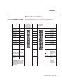
Interface Connections . . . . . . . . . .
Wiring . . . . . . . . . . . . . . . . .
Electromagnetic Compatibility . . .
Qualified AC Line Filters. . . . . . .
Allen-Bradley AC Line Filters . . . .
Chapter 6
. . . . . . . . . . . . . . . 3-3
Unpacking, Inspecting and Storing
Unpacking the Drive . .
Inspection Procedure . .
Testing the Unit . . . . .
Hardware Setup . . .
Drive Checkout Test
Storing the Unit . . . . .
Chapter 5
. . . . . . . . . . . . . . . 3-1
. . . . . . . . . . . . . . . 3-2
. . . . . . . . . . . . . . . . . 6-1
. . . . . . . . . . . . . . . . . 6-3
. . . . . . . . . . . . . . . . . 6-4
. . . . . . . . . . . . . . . . . 6-9
. . . . . . . . . . . . . . . . 6-14
. . . . . . . . . . . . . . . . 6-16
. . . . . . . . . . . . . . . . 6-17
. . . . . . . . . . . . . . . . 6-19
. . . . . . . . . . . . . . . . 6-21
. . . . . . . . . . . . . . . . 6-26
. . . . . . . . . . . . . . . . 6-27
Table of Contents
J2 Terminal Strip/Breakout Board
J3 – Auxiliary Port . . . . . . . . . .
J4 and J5 – Serial Port . . . . . . . .
Serial Communications Overview
RS-232 Connections . . . . . . . .
Four Wire RS-485 Connections . .
A1, A2, and COM – Analog Outputs
Interface Connections . . . . . . . . .
Chapter 7
. . . . . . . . . . . . . . . . 6-30
. . . . . . . . . . . . . . . . 6-31
. . . . . . . . . . . . . . . . 6-34
. . . . . . . . . . . . . . . . 6-36
. . . . . . . . . . . . . . . . 6-38
. . . . . . . . . . . . . . . . 6-40
. . . . . . . . . . . . . . . . 6-44
. . . . . . . . . . . . . . . . 6-45
Power Connections
TB1 – DC Bus and AC Power
Motor Power Cabling . . .
Motor Overload Protection
Emergency Stop Wiring . .
DC Bus . . . . . . . . . . . .
AC Power Cabling . . . . .
Auxiliary Power . . . . . .
TB2 – Shunt Regulator . . . .
External Shunt Connection
Chapter 8
Intro-3
. . . . . . . . . . . . . . . . . . . . . 7-1
. . . . . . . . . . . . . . . . . . . . . 7-3
. . . . . . . . . . . . . . . . . . . . . 7-5
. . . . . . . . . . . . . . . . . . . . . 7-6
. . . . . . . . . . . . . . . . . . . . . 7-6
. . . . . . . . . . . . . . . . . . . . . 7-7
. . . . . . . . . . . . . . . . . . . . 7-10
. . . . . . . . . . . . . . . . . . . . 7-11
. . . . . . . . . . . . . . . . . . . . 7-14
Application and Configuration Examples
Analog Control . . . . . . . . . . . . .
Hardware Setup . . . . . . . . . . .
Connection Diagram . . . . . . . .
Configuration . . . . . . . . . . . .
Tuning . . . . . . . . . . . . . . .
Operation . . . . . . . . . . . . . .
Preset Controller . . . . . . . . . . . .
Hardware Setup . . . . . . . . . . .
Connection Diagram . . . . . . . .
Configuration . . . . . . . . . . . .
Tuning . . . . . . . . . . . . . . .
Operation . . . . . . . . . . . . . .
Position Follower (Master Encoder) .
Hardware Setup . . . . . . . . . . .
Connection Diagram . . . . . . .
Configuration . . . . . . . . . . . .
Tuning . . . . . . . . . . . . . . . .
Operation . . . . . . . . . . . . . .
Position Follower (Step/Direction) .
Hardware Setup . . . . . . . . . . .
Connection Diagram . . . . . . . .
Configuration . . . . . . . . . . . .
Tuning . . . . . . . . . . . . . . . .
. . . . . . . . . . . . . . . . . 8-1
. . . . . . . . . . . . . . . . . 8-1
. . . . . . . . . . . . . . . . . 8-2
. . . . . . . . . . . . . . . . . 8-3
. . . . . . . . . . . . . . . . . 8-4
. . . . . . . . . . . . . . . . . 8-5
. . . . . . . . . . . . . . . . . 8-6
. . . . . . . . . . . . . . . . . 8-6
. . . . . . . . . . . . . . . . . 8-8
. . . . . . . . . . . . . . . . . 8-8
. . . . . . . . . . . . . . . . 8-10
. . . . . . . . . . . . . . . . 8-11
. . . . . . . . . . . . . . . . 8-12
. . . . . . . . . . . . . . . . 8-12
. . . . . . . . . . . . . . . . 8-13
. . . . . . . . . . . . . . . . 8-13
. . . . . . . . . . . . . . . . 8-15
. . . . . . . . . . . . . . . . 8-16
. . . . . . . . . . . . . . . . 8-17
. . . . . . . . . . . . . . . . 8-17
. . . . . . . . . . . . . . . . 8-18
. . . . . . . . . . . . . . . . 8-18
. . . . . . . . . . . . . . . . 8-20
Publication 1398-5.0 – October 1998
Intro-4
Table of Contents
Operation . . . . . . . . . . . . . . . . .
Position Follower (Step Up/Step Down) .
Hardware Setup . . . . . . . . . . . . .
Connection Diagram . . . . . . . . . .
Configuration . . . . . . . . . . . . . .
Tuning . . . . . . . . . . . . . . . . . .
Operation . . . . . . . . . . . . . . . . .
Incremental Indexing . . . . . . . . . . .
Hardware Setup . . . . . . . . . . . . .
Connection Diagram . . . . . . . . . .
Configuration . . . . . . . . . . . . . .
Tuning . . . . . . . . . . . . . . . . . .
Operation . . . . . . . . . . . . . . . . .
Registration Indexing . . . . . . . . . . .
Hardware Setup . . . . . . . . . . . . .
Connection Diagram . . . . . . . . . .
Configuration . . . . . . . . . . . . . .
Tuning . . . . . . . . . . . . . . . . . .
Operation . . . . . . . . . . . . . . . . .
Absolute Indexing . . . . . . . . . . . . .
Hardware Setup . . . . . . . . . . . . .
Connection Diagram . . . . . . . . . .
Configuration . . . . . . . . . . . . . .
Tuning . . . . . . . . . . . . . . . . . .
Operation . . . . . . . . . . . . . . . . .
Modifying User Units . . . . . . . . . . .
Changing the Display Units Settings .
Chapter 9
. . . . . . . . . . . . . . 8-22
. . . . . . . . . . . . . . 8-22
. . . . . . . . . . . . . . 8-23
. . . . . . . . . . . . . . 8-23
. . . . . . . . . . . . . . 8-25
. . . . . . . . . . . . . . 8-26
. . . . . . . . . . . . . . 8-27
. . . . . . . . . . . . . . 8-28
. . . . . . . . . . . . . . 8-29
. . . . . . . . . . . . . . 8-29
. . . . . . . . . . . . . . 8-31
. . . . . . . . . . . . . . 8-32
. . . . . . . . . . . . . . 8-33
. . . . . . . . . . . . . . 8-34
. . . . . . . . . . . . . . 8-35
. . . . . . . . . . . . . . 8-35
. . . . . . . . . . . . . . 8-37
. . . . . . . . . . . . . . 8-38
. . . . . . . . . . . . . . 8-39
. . . . . . . . . . . . . . 8-39
. . . . . . . . . . . . . . 8-40
. . . . . . . . . . . . . . 8-41
. . . . . . . . . . . . . . 8-43
. . . . . . . . . . . . . . 8-44
. . . . . . . . . . . . . . 8-45
. . . . . . . . . . . . . . 8-45
Tuning
Tuning Guidelines . . . . . . . . . .
General Tuning Rules . . . . . . .
High Inertia Loads . . . . . . . . .
Mechanical Resonance . . . . . .
Backlash . . . . . . . . . . . . . .
Auto Tune Mode . . . . . . . . . . .
Auto Tuning . . . . . . . . . . . .
Manual Tune Mode . . . . . . . . . .
Gains . . . . . . . . . . . . . . . .
Filters . . . . . . . . . . . . . . . .
Manual Tuning . . . . . . . . . . .
Velocity Loop Tuning Examples
Chapter 10
. . . . . . . . . . . . . . 8-21
. . . . . . . . . . . . . . . . . . 9-1
. . . . . . . . . . . . . . . . . . 9-1
. . . . . . . . . . . . . . . . . . 9-1
. . . . . . . . . . . . . . . . . . 9-2
. . . . . . . . . . . . . . . . . . 9-3
. . . . . . . . . . . . . . . . . . 9-4
. . . . . . . . . . . . . . . . . . 9-4
. . . . . . . . . . . . . . . . . . 9-6
. . . . . . . . . . . . . . . . . . 9-6
. . . . . . . . . . . . . . . . . . 9-7
. . . . . . . . . . . . . . . . . . 9-8
. . . . . . . . . . . . . . . . . 9-10
Status Display
Operating Messages . . . . . . . . . . . . . . . . . . . . . . . . . . 10-1
Publication 1398-5.0 – October 1998
Table of Contents
Intro-5
Error Messages . . . . . . . . . . . . . . . . . . . . . . . . . . . . . 10-2
Run-Time Error Codes . . . . . . . . . . . . . . . . . . . . . . . 10-2
Power-Up Error Codes . . . . . . . . . . . . . . . . . . . . . . . 10-3
Chapter 11
Maintenance and Troubleshooting
Maintenance . . . . . . . . . . . . . . . . . . . . . . . . .
Periodic Maintenance . . . . . . . . . . . . . . . . . .
Fuse Replacement . . . . . . . . . . . . . . . . . . . .
EEPROM Personality Module . . . . . . . . . . . . .
Firmware Upgrading . . . . . . . . . . . . . . . . . . . .
Firmware Upgrade Procedure using ULTRA Master .
Troubleshooting . . . . . . . . . . . . . . . . . . . . . . .
Error Codes . . . . . . . . . . . . . . . . . . . . . . . .
RS-232 Communication Test . . . . . . . . . . . . . .
Testing Digital Outputs . . . . . . . . . . . . . . . . .
Testing Digital Inputs . . . . . . . . . . . . . . . . . .
Testing Analog Outputs . . . . . . . . . . . . . . . . .
Testing Positive and Negative Current Limits. . . . .
Testing Encoder Inputs . . . . . . . . . . . . . . . . . .
Appendix A
. . . . . 11-1
. . . . . 11-2
. . . . . 11-5
. . . . . 11-5
. . . . . 11-6
. . . . . 11-6
. . . . . 11-11
. . . . . 11-12
. . . . . 11-14
. . . . . 11-14
. . . . . 11-15
. . . . . 11-17
. . . . . . . . . . . . . . . . . . . . . . . A-1
. . . . . . . . . . . . . . . . . . . . . . . A-2
. . . . . . . . . . . . . . . . . . . . . . . A-2
. . . . . . . . . . . . . . . . . . . . . . . A-3
. . . . . . . . . . . . . . . . . . . . . . . A-3
. . . . . . . . . . . . . . . . . . . . . . . A-3
. . . . . . . . . . . . . . . . . . . . . . . A-4
. . . . . . . . . . . . . . . . . . . . . . . A-5
. . . . . . . . . . . . . . . . . . . . . . . A-6
. . . . . . . . . . . . . . . . . . . . . . . A-6
Cable Diagrams, Schematics and Examples
Interface Cables . . . . . . . . . . . . . . . . . . . .
Serial Interface Cables . . . . . . . . . . . . . . . .
Encoder Feedback Cables . . . . . . . . . . . . . . .
Motor Power Cables . . . . . . . . . . . . . . . . .
Cabling Examples . . . . . . . . . . . . . . . . . . .
Allen-Bradley 9/Series CNC Family Connections .
Appendix C
. . . . . 11-1
Options and Accessories
ULTRA 200 Series Drives
Fuses . . . . . . . . . . . .
Options and Accessories .
Publications . . . . . . . . .
Interface Cables . . . . . .
Serial Interface Cables . .
Encoder Feedback Cables .
Motor Power Cables . . . .
Connector Kits . . . . . . .
Mating Connectors. . . . .
Appendix B
. . . . . 11-1
. . . . . . . . . B-3
. . . . . . . . B-11
. . . . . . . . B-14
. . . . . . . . B-21
. . . . . . . . B-26
. . . . . . . . B-30
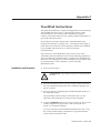
TouchPad Instructions
Installation and Operation. . . . . . . . . . . . . . . . . . . . . . . . C-1
TouchPad Commands . . . . . . . . . . . . . . . . . . . . . . . . . . C-3
Supplemental Instructions . . . . . . . . . . . . . . . . . . . . . . . C-6
Publication 1398-5.0 – October 1998
Intro-6
Table of Contents
Motor Selection
Displays . . . .
Motor Table . . . .
TouchPad Options
TouchPad Lists . .
Appendix D
. . . . . . . . . . . . . . . . . . . . . . . . . . . .C-6
. . . . . . . . . . . . . . . . . . . . . . . . . . . .C-6
. . . . . . . . . . . . . . . . . . . . . . . . . . . C-10
. . . . . . . . . . . . . . . . . . . . . . . . . . . C-12
. . . . . . . . . . . . . . . . . . . . . . . . . . . C-13
Creating Custom Motor Files
Drive and Motor File Configuration with ULTRA Master
Motor Parameter Set . . . . . . . . . . . . . . . . . . . .
General Parameters . . . . . . . . . . . . . . . . . . . . .
Feedback Parameters . . . . . . . . . . . . . . . . . . . .
Electrical Parameters . . . . . . . . . . . . . . . . . . . .
Rating Parameters . . . . . . . . . . . . . . . . . . . . . .
Example of Custom Motor File Creation . . . . . . . . . .
Manufacturer’s Data . . . . . . . . . . . . . . . . . . . . .
Parameter Conversions . . . . . . . . . . . . . . . . . . .
Custom Motor File . . . . . . . . . . . . . . . . . . . . .
Troubleshooting Custom Motor Files . . . . . . . . . . . .
Appendix E
. . . . D-2
. . . . D-5
. . . . D-8
. . . . D-10
. . . . D-11
. . . . D-14
. . . . D-14
. . . . D-15
. . . . D-16
. . . . D-16
Electromagnetic Compatibility Guidelines
for Machine Design
Filtering . . . . . . . . . . .
AC Line Filter Selection
Grounding . . . . . . . . . .
Shielding and Segregation .
Appendix F
. . . . D-2
. . . . . . . . . . . . . . . . . . . . . . .E-2
. . . . . . . . . . . . . . . . . . . . . . .E-3
. . . . . . . . . . . . . . . . . . . . . . .E-5
. . . . . . . . . . . . . . . . . . . . . . .E-6
Dynamic Braking Resistor Selection
Dynamic Braking Equations. . . . . . . . . . . . . . . . . . . . . . . F-1
Sample Calculations. . . . . . . . . . . . . . . . . . . . . . . . . . F-3
Appendix G
Specifications
Power . . . . . . . . . . . . . . . . . . . . . . . . . . . . . . . . . . G-5
Power Dissipation . . . . . . . . . . . . . . . . . . . . . . . . . . . G-7
Index
Publication 1398-5.0 – October 1998
Index-1
List of Figures
IntroList of Figures
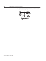
Product Parts Explained . . . . . . . . . . . . . . . . . . . . . Intro-21
Chapter 1
Safety
Chapter 2
Selecting Other System Components
Chapter 3
ULTRA Master Installation
Chapter 4
Unpacking, Inspecting and Storing
Connection Diagram . . . . . . . . . . . . . . . . . . . . . . . . . . . 4-4
Chapter 5
Installation
1398-DDM Mounting Dimensions (sheet 1 of 2) . . .
MDF AC Line Filter Mounting Diagrams . . . . . .
MIF Single Phase AC Line Filter Mounting Diagram
Power Wiring Diagrams (sheet 1 of 3) . . . . . . . . .
Chapter 6
.
.
.
.
.
.
.
.
.
.
.
.
.
.
.
.
.
.
.
.
.
.
.
.
.
.
.
.
. 5-3
. 5-8
5-10
5-11
Digital Input Circuit . . . . . . . . . . . . . . . . . . . . . . . . .
Drive Input Connected to a Switch/Relay Contact . . . . . . .
Drive Input Connected to an Opto-Isolator . . . . . . . . . . . .
Drive Input Connected to an Active High Sourcing Transistor
Drive Input Connected to Active Low Output using
a Switch/Relay . . . . . . . . . . . . . . . . . . . . . . . . . .
Drive Input Connected to Active Low Output using
an Opto-Isolator . . . . . . . . . . . . . . . . . . . . . . . . .
Drive Input Connected to Sourcing Output . . . . . . . . . . .
READY and BRAKE Circuits . . . . . . . . . . . . . . . . . . . .
Digital Output Circuit . . . . . . . . . . . . . . . . . . . . . . . .
Drive Output Connected to an Opto-Isolator . . . . . . . . . . .
Drive Output Connected to an LED Indicator . . . . . . . . . .
Drive Output Connected to a Resistive Load . . . . . . . . . . .
Drive Output Connected to a Switch/Relay . . . . . . . . . . .
Drive Output Connected to Active Low Input using
a Switch/Relay . . . . . . . . . . . . . . . . . . . . . . . . . .
Drive Output Connected to Active Low Input using
an Opto-Isolator . . . . . . . . . . . . . . . . . . . . . . . . .
Drive Output Connected to Active High (Sinking) Input . . . .
Positive and Negative Current Limit Circuits . . . . . . . . . .
Analog COMMAND Input Circuit . . . . . . . . . . . . . . . .
ANALOG 1 and ANALOG 2 Output Circuits . . . . . . . . . .
Output Encoder Interface Circuit . . . . . . . . . . . . . . . . .
Auxiliary Encoder Input Types . . . . . . . . . . . . . . . . . .
Auxiliary Encoder Input Circuit . . . . . . . . . . . . . . . . . .
.
.
.
.
. 6-4
. 6-7
. 6-7
. 6-7
Interfaces
. . 6-7
.
.
.
.
.
.
.
.
. 6-8
. 6-8
. 6-9
6-10
6-11
6-12
6-12
6-12
. 6-13
.
.
.
.
.
.
.
.
6-13
6-13
6-14
6-15
6-16
6-17
6-19
6-19
Publication 1398-5.0 – October 1998
Intro-8
List of Figures
External Encoder Interface via TTL Differential Line Drivers .
Complementary Encoder Interface via 7406 Line Drivers
with Pull-up Resistors . . . . . . . . . . . . . . . . . . . . . .
Complementary Encoder Interface via Standard TTL Logic . .
Single-Ended Encoder Interface via Open Collector
Transistor without Pull-up (not recommended) . . . . . . .
Single-Ended Encoder Interface via Standard TTL Signals
(not recommended) . . . . . . . . . . . . . . . . . . . . . . .
Single-Ended Encoder Interface via Open Collector Transistor
with 5 VDC to 12 VDC Pull-up (not recommended) . . . .
Single-Ended Encoder Interface via Open Collector
Transistor with 24 VDC Pull-up (not recommended) . . . .
External Step/Direction Interface via TTL Differential
Line Drivers . . . . . . . . . . . . . . . . . . . . . . . . . . .
External Step/Direction Interface via Single-Ended
TTL Line Drivers (not recommended) . . . . . . . . . . . .
External CW/CCW (Step Up/Step Down) Interface via TTL
Differential Line Drivers . . . . . . . . . . . . . . . . . . . .
External CW/CCW (Step Up/Step Down) Interface via
Single-Ended Line Drivers (not recommended) . . . . . . .
Motor Encoder Interface Circuit . . . . . . . . . . . . . . . . .
Hall Effect Sensor Circuit . . . . . . . . . . . . . . . . . . . . .
ULTRA 200 Series Motor Encoder Connections . . . . . . . . .
RS-232/485 Interface Circuit . . . . . . . . . . . . . . . . . . .
Sixteen Position Rotary Addressing Switch . . . . . . . . . . .
RS-232 Connection Diagrams . . . . . . . . . . . . . . . . . . .
RS-485/RS-422 Communication Comparison . . . . . . . . .
Four Wire RS-485 Daisy Chain Connection Diagram . . . . . .
RS-232 to RS-485 Multi-Drop Connection Diagram . . . . . . .
ANALOG 1 and ANALOG 2 Output Circuits . . . . . . . . .
1398-DDM Interface Connection Diagram . . . . . . . . . . . .
Chapter 7
Publication 1398-5.0 – October 1998
. . 6-21
. . 6-22
. . 6-22
. . 6-23
. . 6-23
. . 6-24
. . 6-25
. . 6-25
. . 6-25
.
.
.
.
.
.
.
.
.
.
.
.
. 6-26
. 6-28
. 6-28
. 6-30
. 6-34
. 6-36
. 6-38
. 6-40
. 6-42
. 6-43
. 6-44
. 6-45
Power Connections
Motor Power EMC Shield Connection
Pigtail Ground . . . . . . . . . . . . .
Emergency Stop Contactor Wiring . .
External Shunt Wiring Examples . . .
External Shunt Mounting Diagram . .
Chapter 8
. . 6-21
.
.
.
.
.
.
.
.
.
.
.
.
.
.
.
.
.
.
.
.
.
.
.
.
.
.
.
.
.
.
.
.
.
.
.
.
.
.
.
.
.
.
.
.
.
.
.
.
.
.
.
.
.
.
.
.
.
.
.
.
.
.
.
.
.
.
.
.
.
.
.
.
.
.
.
. 7-3
. 7-4
. 7-7
. 7-13
. 7-14
Analog Controller Connection Diagram . . . . . . . .
Preset Controller Connection Diagram . . . . . . . . .
Master Encoder Connection Diagram . . . . . . . . .
Step/Direction Controller Connection Diagram . . .
Step Up/Step Down Controller Connection Diagram
Incremental Indexing Examples . . . . . . . . . . . .
Incremental Indexing Connection Diagram . . . . . .
Registration Indexing Examples . . . . . . . . . . . .
.
.
.
.
.
.
.
.
.
.
.
.
.
.
.
.
.
.
.
.
.
.
.
.
.
.
.
.
.
.
.
.
.
.
.
.
.
.
.
.
.
.
.
.
.
.
.
.
. 8-2
. 8-8
. 8-13
. 8-18
. 8-23
. 8-27
. 8-29
. 8-33
Application and Configuration Examples
List of Figures
Registration Indexing Connection Diagram
Absolute Indexing Examples . . . . . . . . .
Absolute Indexing Connection Diagram . .
PC Display Units – Default Dialog . . . . . .
Chapter 9
Intro-9
.
.
.
.
.
.
.
.
.
.
.
.
.
.
.
.
.
.
.
.
.
.
.
.
.
.
.
.
.
.
.
.
.
.
.
.
.
.
.
.
.
.
.
.
.
.
.
.
8-35
8-39
8-40
8-45
.
.
.
.
.
.
.
.
.
.
.
.
.
.
.
.
.
.
.
.
.
.
.
.
.
.
.
.
.
.
.
.
.
.
.
.
.
.
.
.
.
.
.
.
.
.
.
.
.
.
.
.
.
.
.
.
.
.
.
.
.
.
.
.
.
.
.
.
.
.
.
.
. 9-3
. 9-3
9-10
9-11
9-11
9-12
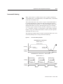
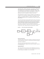
Tuning
Velocity Loop Structure . . . . . . . . . .
Torque Current Conditioning Structure .
Signal Nomenclature . . . . . . . . . . .
Underdamped Signal . . . . . . . . . . .
Overdamped Signal . . . . . . . . . . . .
Critically Damped Signal (Ideal Tuning)
.
.
.
.
.
.
.
.
.
.
.
.
Chapter 10
Status Display
Chapter 11
Maintenance and Troubleshooting
Fuse and Jumper Locations
. . . . . . . . . . . . . . . . . . . . . 11-4
Appendix A
Options and Accessories
Appendix B
Cable Diagrams, Schematics and Examples
J1 to J3 Interface Cable (P/N 9101-1367) . . . . . . . . . . .
J1 to No Connector Interface Cable (P/N 9101-1370) . . .
J3 to J3 Interface Cable (P/N 9101-1463) . . . . . . . . . . .
J3 to No Connector Interface Cable (P/N 9101-1368) . . .
J1 to 50-pin Terminal Block Kit Diagram
(P/N 9101-1391 and 9101-1560) . . . . . . . . . . . . .
J1 to 50-pin D-Connector Cable (P/N 9101-1369) . . . . .
J2 to 25-pin Terminal Block Kit Diagram (P/N 9101-1392)
J2 to 25-pin D-Connector Cable (P/N 9101-1371) . . . . .
J5 to 9-pin D-Shell Interface Diagram (P/N 9101-1372) . .
J5 to J5 Serial Interface Cable (P/N 9101-1374) . . . . . . .
J5 to No Connector Serial Interface Cable (P/N 9101-1379)
F- or H-Series Motors to No Connector Encoder Cable
(P/N 9101-1365) . . . . . . . . . . . . . . . . . . . . . .
J2 to F- or H-Series Encoder Cable (P/N 9101-1366) . . . .
J2 to Y-Series Encoder Cable (P/N 9101-1375) . . . . . . .
No Connector to Y-Series Encoder Cable (P/N 9101-1373)
J2 to No Connector Encoder Cable (P/N 9101-1380) . . . .
J2 to N-Series Encoder Cable (P/N 9101-1468) . . . . . . .
No Connector to N-Series Encoder Cable (P/N 9101-1469)
2000 or 3000 F- or H-Series Power Cable (P/N 9101-1381)
4000 F- or H-Series Power Cable (P/N 9101-1382) . . . . .
6100 or 6200 F- or H-Series Power Cable (P/N 9101-1383)
6300 H-Series Power Cable (P/N 9101-1399) . . . . . . . .
8000 H-Series Power Cable (P/N 9101-1384) . . . . . . . .
Y-Series Power Cable (P/N 9101-1385) . . . . . . . . . . .
.
.
.
.
.
.
.
.
.
.
.
.
.
.
.
.
. B-3
. B-4
. B-5
. B-6
.
.
.
.
.
.
.
.
.
.
.
.
.
.
.
.
.
.
.
.
.
.
.
.
.
.
.
.
. B-7
. B-8
. B-9
B-10
B-11
B-12
B-13
.
.
.
.
.
.
.
.
.
.
.
.
.
.
.
.
.
.
.
.
.
.
.
.
.
.
.
.
.
.
.
.
.
.
.
.
.
.
.
.
.
.
.
.
.
.
.
.
.
.
.
.
B-14
B-15
B-16
B-17
B-18
B-19
B-20
B-21
B-22
B-22
B-23
B-23
B-24
Publication 1398-5.0 – October 1998
Intro-10
List of Figures
N-Series Power Cable (P/N 9101-1467) . . . . . .
F or H-Series Motors to ULTRA 200 Series Drive
F- or H-Series Motors to ULTRA 200 Series Drive
using P2 Terminal Strip . . . . . . . . . . . . . .
Y-Series Motors to ULTRA 200 Series Drive . . . .
Y-Series Motors to ULTRA 200 Series Drive
using P2 Terminal Strip . . . . . . . . . . . . . .
Appendix C
. . . . . . . . .B-25
. . . . . . . .B-26
. . . . . . . . .B-27
. . . . . . . . .B-28
. . . . . . . . .B-29
TouchPad Instructions
TouchPad Connection and Pinouts . . . . . . . . . . . . . . . . . . C-2
TouchPad Version Number Display . . . . . . . . . . . . . . . . . C-2
TouchPad Command Tree (sheet 1 of 2) . . . . . . . . . . . . . . . C-4
Appendix D
Creating Custom Motor Files
Allen-Bradley Motor Naming Convention . . . . . . .
Required Back-EMF and Hall Signal Phasing
for Clockwise Rotation . . . . . . . . . . . . . . . . .
Phasing of the Encoder Signals for Clockwise Rotation
Index Offsets . . . . . . . . . . . . . . . . . . . . . . . .
Hall Offsets . . . . . . . . . . . . . . . . . . . . . . . . .
Motor Thermal Protection Software Method . . . . . .
Back-EMF and Hall Signals, Clockwise Rotation . . . .
Appendix E
. . . . . . D-3
.
.
.
.
.
.
.
.
.
.
.
.
.
.
.
.
.
.
.
.
.
.
.
.
.
.
.
.
.
.
. D-4
. D-4
. D-8
. D-9
D-13
D-14
Electromagnetic Compatibility Guidelines
for Machine Design
EMI Source-Victim Model . . . . . . . . . . . . . . . . . . . . . . E-2
Single Point Ground Types . . . . . . . . . . . . . . . . . . . . . . E-5
Appendix F
Dynamic Braking Resistor Selection
Appendix G
Specifications
Publication 1398-5.0 – October 1998
List of Tables
IntroList of Tables
Chapter 1
Safety
Chapter 2
Selecting Other System Components
Chapter 3
ULTRA Master Installation
Chapter 4
Unpacking, Inspecting and Storing
Chapter 5
Installation
Qualified AC Line Filters . . . . . . . . . . . . . . . . . . . . . . . . 5-7
MDF AC Line Filter Dimensions . . . . . . . . . . . . . . . . . . . . 5-9
MIF AC Line Filter Dimensions. . . . . . . . . . . . . . . . . . . . 5-10
Chapter 6
Interfaces
24 Volt Power Supply Specifications . . . . . . . . . . . . . . .
5 Volt Power Supply Specifications . . . . . . . . . . . . . . .
General and Dedicated Inputs . . . . . . . . . . . . . . . . . .
INPUT1, INPUT2, INPUT3, INPUT4
and FAULT RESET Functions . . . . . . . . . . . . . . . . .
Digital Input Specifications . . . . . . . . . . . . . . . . . . . .
READY Output Specifications . . . . . . . . . . . . . . . . . .
BRAKE Output Specifications. . . . . . . . . . . . . . . . . . .
General and Dedicated Outputs . . . . . . . . . . . . . . . . .
OUTPUT1, OUTPUT2, OUTPUT3 and OUTPUT4 Functions .
Transistor Output Specifications . . . . . . . . . . . . . . . . .
Analog Inputs +I LIMIT and -I LIMIT . . . . . . . . . . . . . .
Positive and Negative Current Limit Imput Specification . . .
Analog Command Input. . . . . . . . . . . . . . . . . . . . . .
Analog Command Input Specifications . . . . . . . . . . . . .
Analog Outputs: ANALOG 1 and ANALOG 2 . . . . . . . . .
Analog Output Specifications . . . . . . . . . . . . . . . . . . .
Motor Encoder Output Signal. . . . . . . . . . . . . . . . . . .
Motor Encoder Output Specifications . . . . . . . . . . . . . .
Auxiliary Encoder/Step and Diection/CW & CCW
(Step Up & Down) Signals . . . . . . . . . . . . . . . . . . .
Quadrature Interface Specifications . . . . . . . . . . . . . . .
Step/Direction and CW/CCW (Step Up/Step Down)
Interface Specifications . . . . . . . . . . . . . . . . . . . . .
J2- Motor Encoder Connector Pin-Outs . . . . . . . . . . . . .
J3 – Auxiliary Connector Pin-Outs . . . . . . . . . . . . . . . .
J4 and J5 – Serial Port Connector Pin-Outs . . . . . . . . . . .
Drive Addressing . . . . . . . . . . . . . . . . . . . . . . . . .
Analog outputs ANALOG 1 and ANALOG 2 . . . . . . . . .
. . . 6-3
. . . 6-4
. . . 6-5
.
.
.
.
.
.
.
.
.
.
.
.
.
.
.
.
.
.
.
.
.
.
.
.
.
.
.
.
.
.
. 6-5
. 6-6
. 6-9
6-10
6-10
6-10
6-11
6-14
6-14
6-15
6-15
6-16
6-17
6-18
6-18
. . 6-20
. . 6-20
.
.
.
.
.
.
.
.
.
.
.
.
6-24
6-28
6-32
6-35
6-36
6-44
Publication 1398-5.0 – October 1998
Intro-12
List of Tables
Chapter 7
Power Connections
TB1 – Motor Power Terminals . . . . . . . . . . . . . . . . .
Motor Power Contact and Wire Sizing Recommendations .
TB1 – DC Bus Terminals . . . . . . . . . . . . . . . . . . . .
TB1 – AC Power Terminals. . . . . . . . . . . . . . . . . . .
AC Input Power Sizing Requirements . . . . . . . . . . . .
Auxiliary Power Terminals. . . . . . . . . . . . . . . . . . .
Auxiliary Power Sizing Requirements . . . . . . . . . . . .
TB2 – Shunt Regulator Terminals . . . . . . . . . . . . . . .
Internal Shunt Power Ratings for Drive Models . . . . . .
Maximum External Shunt Power Ratings for Drive Models
Minimum Ratings for Customer Supplied External
Shunt Resistor . . . . . . . . . . . . . . . . . . . . . . . .
Chapter 8
.
.
.
.
.
.
.
.
.
.
.
.
.
.
.
.
.
.
.
.
.
.
.
.
.
.
.
.
.
.
. 7-3
. 7-5
. 7-7
. 7-8
. 7-9
. 7-10
. 7-10
. 7-12
. 7-12
. 7-12
. . . . 7-13
Application and Configuration Examples
Preset Binary Inputs . . . . . . . . . . . . . . . . . . . . . . . . . . 8-6
Chapter 9
Tuning
Velocity Loop Gains . . . . . . . . . . . . . . . . . . . . . . . . . . 9-6
Position Loop Gains . . . . . . . . . . . . . . . . . . . . . . . . . . 9-7
Chapter 10
Status Display
Run-Time Error Codes . . . . . . . . . . . . . . . . . . . . . . . . . 10-2
Power-Up Error Codes . . . . . . . . . . . . . . . . . . . . . . . . . 10-4
Chapter 11
Maintenance and Troubleshooting
Troubleshooting Guide . . . . . . . . . . . . . . . . . . . . . . . . 11-6
Appendix A
Options and Accessories
Appendix B
Cable Diagrams, Schematics and Examples
9/260 or 9/290 to Breakout Board.
9/260 or 9/290 to J1 Connector . .
9/230 to Breakout Board . . . . . .
9/230 to J1 Connector . . . . . . . .
Appendix C
Publication 1398-5.0 – October 1998
.
.
.
.
.
.
.
.
.
.
.
.
.
.
.
.
.
.
.
.
.
.
.
.
.
.
.
.
.
.
.
.
.
.
.
.
.
.
.
.
.
.
.
.
.
.
.
.
.
.
.
.
.
.
.
.
.
.
.
.
.
.
.
.
.
.
.
.
.B-30
.B-30
.B-30
.B-31
TouchPad Fault/Error/Warning Displays . . . . . . . .
TouchPad Motor Table Identification by Motor Series . .
TouchPad Motor Table Identification by Motor ID . . . .
Option Selections for the TouchPad . . . . . . . . . . . .
Drive Communications Parameter List for the TouchPad
Baud Rate Parameter List for TouchPad . . . . . . . . . .
Encoder Output Parameter List for TouchPad . . . . . .
IO Mode Parameter List for TouchPad . . . . . . . . . . .
Index Pointer Parameter List for TouchPad . . . . . . . .
Index Termination Parameter List for TouchPad . . . . .
.
.
.
.
.
.
.
.
.
.
.
.
.
.
.
.
.
.
.
.
.
.
.
.
.
.
.
.
.
.
.
.
.
.
.
.
.
.
.
.
. C-9
.C-10
.C-11
.C-12
.C-13
.C-13
.C-13
.C-13
.C-14
.C-14
TouchPad Instructions
List of Tables
Home Type Parameter List for TouchPad . . . . .
Homing Auto-Start Parameter List for TouchPad
Reverse Enable for Homing . . . . . . . . . . . . .
Digital Input Parameter List for TouchPad . . . .
Digital Output Parameter List for TouchPad . . .
Analog Output Parameter List for TouchPad . .
Drive Status List for TouchPad . . . . . . . . . . .
Input Flags Parameter List for TouchPad . . . . .
Output Flags Parameter List for TouchPad . . . .
.
.
.
.
.
.
.
.
.
.
.
.
.
.
.
.
.
.
Intro-13
.
.
.
.
.
.
.
.
.
Appendix D
Creating Custom Motor Files
Appendix E
Electromagnetic Compatibility Guidelines
for Machine Design
.
.
.
.
.
.
.
.
.
.
.
.
.
.
.
.
.
.
.
.
.
.
.
.
.
.
.
.
.
.
.
.
.
.
.
.
.
.
.
.
.
.
.
.
.
.
.
.
.
.
.
.
.
.
C-14
C-14
C-15
C-15
C-15
C-16
C-16
C-17
C-17
AC Line Filter Installation . . . . . . . . . . . . . . . . . . . . . . . . E-4
Appendix F
Dynamic Braking Resistor Selection
Dynamic Braking Resistor Parameters . . . . . . . . . . . . . . . . F-1
Appendix G
Specifications
ULTRA 200 Series Power Ratings . . . . . . . . . . . . . . . . . . .G-5
Publication 1398-5.0 – October 1998
Intro-14
List of Tables
Publication 1398-5.0 – October 1998
Preface
IntroPreface
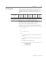
This manual provides a step-by-step approach to building a servo
system using a ULTRA 200 Series drive. The manual is divided into
chapters that cover specific phases of the system design process; from
ordering components that will complement the performance of the
ULTRA 200 Series drive, to receiving, installing and verifying the
drive’s functionality.
Chapters and appendices in the manual include:
●
●
●
●
●
●
●
●
●
●
●
●
●
●
●
●
●
●
Safety
Selecting Other System Components
ULTRA Master Installation
Unpacking, Inspecting and Storing
Installation
Interfaces
Power Connections
Application and Configuration Examples
Tuning
Status Display
Maintenance and Troubleshooting
Options and Accessories
Cable Diagrams, Schematics and Examples
TouchPad Instructions
Creating Custom Motor Files
Electromagnetic Compatibility Guidelines for Machine Design
Dynamic Braking Resistor Selection
Specifications
The intent of the manual is to assemble a high-performance servo
system in a methodical manner. By making correct decisions and
taking appropriate actions a servo system that performs “as designed”
can be assured.
Publication 1398-5.0 – October 1998
Intro-16
Preface
About This Manual
This manual provides instructions on how to setup and connect the
ULTRA 200 Series drive to a controlling device and a motor. A
ULTRA 200 Series drive may operate in one of several different
functional modes. The hardware connections necessary to run the
drive are explained and basic software instructions are provided for
common set up procedures. For detailed explanation of software
instructions, refer to the comprehensive on-line instructions available
in the ULTRA Master software.
This manual explains how to install your ULTRA 200 Series drive
using ULTRA Master software with a personal computer. If you are
using a TouchPad device, abbreviated command titles are displayed
but the setup steps remain the same.
This manual is organized into chapters and appendixes. The topics
covered in each chapter and section are briefly described.
Typographical conventions, warning and cautions specific to the
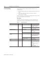
drive, and complementary manuals are also described.
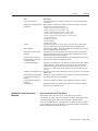
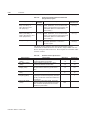
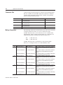
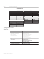
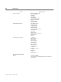
Title
Safety
Selecting Other System
Components
ULTRA Master Installation
Unpacking, Inspecting and
Storing
Installation
Interfaces
Description
Lists general safety requirements that must be followed when installing
or servicing the drive.
Reviews the major features of the ULTRA 200 Series drives and identifies motors and signal types that are compatible.
Explains how to install, access and exit ULTRA Master.
Lists what should be included with your ULTRA 200 Series drive and
instructs you on how to perform a basic functional test before installing
or storing the drive.
Instructs you on how to physically install your ULTRA 200 Series drive.
Provides comprehensive information about the signals available on
each connector. Each signal or set of signals is identified by:
• Power requirements for driving the signal.
• Functions performed by the signal.
• Specifications, including ON and OFF states.
• Schematic depictions of the circuit design for each signal type.
The signals are grouped under the following connectors.
• J1 – Controller
Diagrams show cable connections needed for common interfaces.
• J2 – Encoder
Details information about the encoder signals, Hall Effect switches and
thermostat connections available through this connector.
• J3 – Auxiliary Port
Provides a second controller connection that duplicates the first 26 pins
on J1, the Controller connector
• J4 and J5 – Serial Port
Diagrams and instructions detail how to connect one or more drives
using RS-232 communications in a single or daisy-chain connection, or
to connect several drives using Multi-Drop RS-485.
• A1, A2, and COM – Analog Outputs
Describes the connections that allow monitoring of the analog command signals with external equipment.
Publication 1398-5.0 – October 1998
Preface
Intro-17
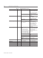
Title
Power Connections
Description
Provides information on making motor power, DC bus and AC Power
connections.
Application and Configuration Describes the hardware and software set up necessary to install the
Examples
drive as one of the following types:
• Analog Control in velocity or torque mode
• Preset Controller in velocity or torque mode
• Position Follower (Master Encoder) in velocity mode
• Position Follower (Step/Direction) in velocity mode
• Position Follower (Step Up/Step Down) in velocity mode
• Incremental Indexing
• Registration Indexing
• Absolute Indexing
• Modifying User Units
Tuning
Status Display
Maintenance and Troubleshooting
Options and Accessories
Cable Diagrams, Schematics and Examples
TouchPad Instructions
Creating Custom Motor Files
Electromagnetic Compatibility Guidelines for Machine
Design
Dynamic Braking Resistor
Selection
Specifications
Additional Instructions and
Manuals
Provides instructions on how to tune a drive and motor combination
using the autotuning or manual tuning features in ULTRA Master.
Discusses the operator indicators available on the front panel. Operating or Error Messages are explained.
Describes the minimal maintenance necessary with the ULTRA 200
Series drives and provides a comprehensive troubleshooting chart of
potential problems and their solutions.
Lists the optional equipment available for the ULTRA 200 Series drives.
Provides schematics and cabling examples.
Describes how to program a ULTRA 200 Series drive using the optional
TouchPad device. Tables reference the various motor types that are
programmed to work with the ULTRA 200 Series drive. A TouchPad
Command Tree card for the current firmware version is bound into the
manual.
Describes how to create a custom motor file for use with an ULTRA 200
Series drive.
Describes common electrical noise problems and suggests methods to
ensure ElectroMagnetic Compatibility.
Provides equations to assist in sizing resistors for dynamic braking.
Details the design and operational specifications for the ULTRA 200
Series drives in a tabular format.
Host Commands and ULTRA Master
All ULTRA 200 Series drives are setup through serial Host
Commands. The drives may be configured directly through the Host
Command language or indirectly through the ULTRA Master
software. ULTRA Master is a graphical user interface that provides a
visual method of accessing the Host Command language through the
Microsoft Windows Operating System.
Publication 1398-5.0 – October 1998
Intro-18
Preface
All documentation for both the Host Commands and ULTRA Master
is on-line. Host Command information is available through a
comprehensive on-line reference manual. ULTRA Master information
is available through Help menus. The on-line documents provide indepth explanations of the Host Command language as well as the
menus, windows and dialog boxes that make ULTRA Master a
convenient method for programming ULTRA 200 Series drives.
●
●
To access the Host Command Reference
Click on the Host Command Reference icon in the
ULTRA Master program group.
To access ULTRA Master Help
Open ULTRA Master by clicking on the ULTRA Master icon in
the ULTRA Master group, and
Press the F1 key.
TouchPad
The optional TouchPad may be used to monitor and configure the
ULTRA 200 Series drive. The TouchPad command structure is similar
to the structure of ULTRA Master, but operates through an
abbreviated keypad interface. The card TouchPad Instructions is
provided with the TouchPad. It describes the installation and
operational instructions in a pocket-sized directory. The TouchPad
Command Tree Card and additional instructions for the TouchPad are
included in the section titled, “TouchPad Instructions” which begins
on page C-1. The TouchPad Command Tree Card is a graphical
presentation of both the operational instructions and the command
structure for the ULTRA 200 Series drives. You may find it
convenient to refer to the card when using the TouchPad with a drive.
Publication 1398-5.0 – October 1998
Preface
Symbols and Conventions
Intro-19
Typographical and Wording Conventions
This manual uses the following typographical and wording
conventions:
Example
»
Description
Text preceded by right guillemet explains how to access the particular function in
the preceding paragraph. For example,
To Start ULTRA Master in Windows
»
Drive Set Up
Choose the icon ULTRA Master.
Text shown in this font and underlined indicates a Hot Key (keystroke combination) to quickly access a command. For example,
Choose Drive Set Up.
ULTRA Master
indicates typing ALT+D followed by ENTER accesses this command.
Text shown in this font is information to enter in a window or dialog box. For
example,
win
Text in lower case bold is information to enter at a keyboard. For example,
Choose the icon ULTRA Master.
To start Windows from the DOS prompt, type win and then
press ENTER.
ALT+F4a
ALT, F, N
Choose
Keys that should be pressed simultaneously are shown with a plus sign (+)
between the key names. This example closes the active window.
Keys that should be pressed in sequence are shown with a comma (,) between
the key names. This example opens the File menu and then opens a new file.
The wording indicates that an icon or a command is to be selected from a window
or a command box. For example, the instruction for accessing the command icon
Drive Set Up states:
Choose Drive Set Up.
Select
The wording indicates that options are to be defined or selected from a list. For
example, the instruction for accessing or entering information states:
Select Drive Type and Motor Model from the respective list
box.
Type
The wording indicates that commands are to be entered into a command box. For
example, the instruction for loading ULTRA Master states:
Type a:setup and then press ENTER.
Tips provide hints or shortcuts that are useful to know. For example,
Note: ULTRA Master always displays the Help menu – Quick Start – when
it is first accessed. To disable this automatic display, choose the menu item
Show Quick Start from the Help menu.
a. Microsoft® Windows™ reserves certain multiple keystroke combinations to activate Windows commands.
Publication 1398-5.0 – October 1998
Intro-20
Preface
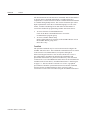
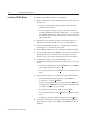
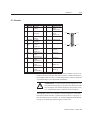
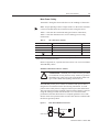
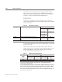
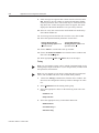
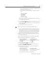
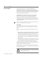
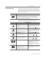
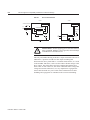
Graphical Symbols and Warning Classifications
This manual uses the following graphical symbols and warning
classifications. The use of a symbol and signal word is based on an
estimation of the likelihood of exposure to the hazardous situation and
what could happen as a result of exposure to the hazard.
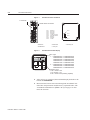
Example
Description
Protective conductor terminal (Earth ground)
Chassis terminal (not a protective ground)
!
Publication 1398-5.0 – October 1998
Symbol plus ATTENTION: These notices provide information
intended to prevent potential personal injury and equipment
damage.
Preface
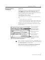
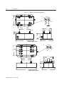
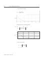
Pictorial Index
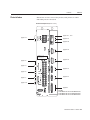
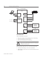
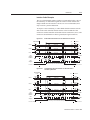
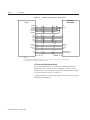
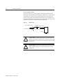
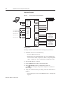
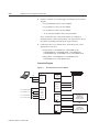
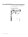
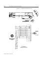
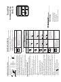
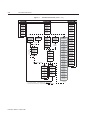
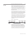
Intro-21
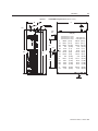
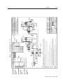
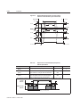
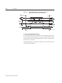
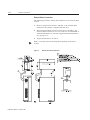
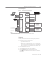
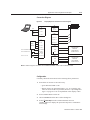
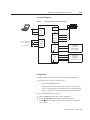
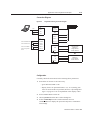
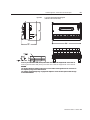
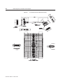
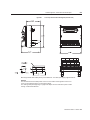
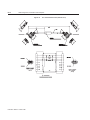
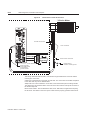
Shown here are face views of the product, with pointers to where
individual parts are discussed.
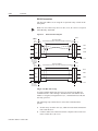
Product Parts Explained (sheet 1 of 3)
Intro
page 10-1, 11-6
page 7-11
page 6-44
page 6-36
page 6-34
WARNING: HIGH VOLTAGE
MAY EXIST FOR UP TO FIVE MINUTES
AFTER REMOVING POWER.
page 7-6
page 6-34
page 7-3
page 6-31
page 7-6
page 7-7
page 6-27
page 7-10
page 6-1
Models:
1398-DDM-010 and 1398-DDM-010X,
1398-DDM-020 and 1398-DDM-020X,
1398-DDM-030 and 1398-DDM-030X
Publication 1398-5.0 – October 1998
Intro-22
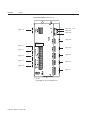
Preface
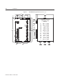
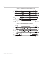
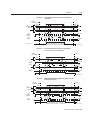
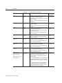
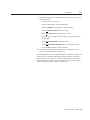
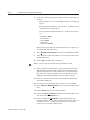
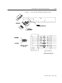
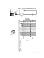
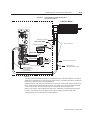
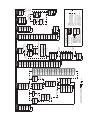
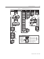
Product Parts Explained (sheet 2 of 3)
Intro
page 10-1, 11-6
page 7-11
page 6-44
page 6-36
page 6-34
WARNING: HIGH VOLTAGE
MAY EXIST FOR UP TO EIGHT MINUTES
AFTER REMOVING POWER.
page 7-6
page 6-34
page 7-3
page 6-31
page 7-6
page 7-7
page 6-27
page 7-10
page 6-1
Models:
1398-DDM-075 and 1398-DDM-075X
Publication 1398-5.0 – October 1998
Preface
Intro-23
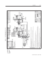
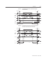
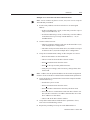
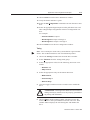
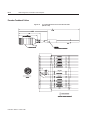
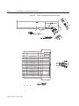
Product Parts Explained (sheet 3 of 3)
Intro
page 10-1, 11-6
page 7-11
page 6-44
page 6-36
page 6-34
WARNING: HIGH VOLTAGE
MAY EXIST FOR UP TO EIGHT MINUTES
AFTER REMOVING POWER.
page 7-6
page 6-34
page 7-3
page 6-31
page 7-6
page 7-7
page 6-27
page 7-10
page 6-1
Models:
1398-DDM-150 and 1398-DDM-150X
Publication 1398-5.0 – October 1998
Intro-24
Preface
Publication 1398-5.0 – October 1998
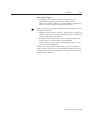
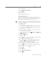
Chapter 1
Safety
Installing and Using the
ULTRA 200 Series
Chapter 1
Read the complete manual before attempting to install or operate the
ULTRA 200 Series drive. By reading the manual you will become
familiar with practices and procedures that allow you to operate the
ULTRA 200 Series drive safely and effectively.
Potential Hazards
The equipment described in this manual is intended for use in
industrial drive systems. This equipment can endanger life through
rotating machinery and high voltages, therefore it is essential that
guards for both electrical and mechanical parts are not removed. The
main hazards which can be encountered in the use of this equipment
are:
●
●
●
●
Electric shock hazards
Electric fire hazards
Mechanical hazards
Stored energy hazards
These hazards must be controlled by suitable machine design, using
the safety guidelines which follow. There are no chemical or ionizing
radiation hazards.
Voltage Potentials
Intro
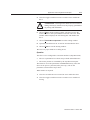
!
ATTENTION: DC bus capacitors may retain hazardous
voltages for several minutes after input power has been
removed, but will normally discharge in several seconds.
Measure the DC bus voltage to verify it has reached a safe
level each time power is removed before working on the
drive; or wait for the time indicated in the warning on the
front of the drive. Failure to observe this precaution could
result in severe bodily injury or loss of life.
Voltage potentials for the internal drive circuitry vary from 325 Volts
above to 325 Volts below earth ground for a 240 Volt input. Voltages
can exceed 450 VDC or 240 VAC within the ULTRA 200 Series. All
circuits, including the connections on the front panel, should be
considered “hot” when main or auxiliary power is connected and for
the time specified in the warning on the front of the drive after power
is removed.
Publication 1398-5.0 – October 1998
1-2
Safety
Your Responsibilities
As the user or person installing this drive, you are responsible for
determining the suitability of the product for the intended application.
Rockwell Automation is neither responsible nor liable for indirect or
consequential damage resulting from the inappropriate use of this
product.
A qualified person is someone who is familiar with all safety notes
and established safety practices, with the installation, operation and
maintenance of this equipment and the hazards involved. For more
detailed definitions, refer to IEC 364.
It is recommended that anyone who operates or maintains electrical or
mechanical equipment should have a basic knowledge of First Aid. As
a minimum, they should know where the First Aid equipment is kept
and the identity of the official First Aiders.
Publication 1398-5.0 – October 1998
Safety
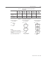
Safety Guidelines
1-3
Electrical shock and fire hazards are avoided by using normal
installation procedures for electrical power equipment in an industrial
environment. Installation must be undertaken by suitably qualified
personnel. Note that this amplifier must be installed in an industrial
cabinet such that access is restricted to suitable qualified personnel.
Mechanical hazards are associated with potentially uncontrolled
movement of the motor shaft. If this imposes a risk in the machine,
then appropriate precautions must be made to electrically disconnect
the motor from the drive when personnel have access to moving parts
of the machine. Note also that the motor must be securely mounted at
all times.
Stored energy hazards are both electrical and mechanical.
●
●
Electrical hazards can be avoided by disconnecting the drive from
its power source and measuring the DC bus voltage to verify it has
reached a safe level or by waiting for the time indicated in the
warning on the front of the drive prior to removing the protective
covers or touching any connections.
Mechanical hazards require a risk analysis on the effects of stored
mechanical energy when the machine is running at speed, as well
as the potential for the conversion of electrical energy stored in
the drive being converted to mechanical energy. Electrical energy
may be stored in drive for the time indicated in the warning on the
front of the drive.
The following points should be observed for the safety of personnel.
These safety notes do not represent a complete list of the steps
necessary to ensure safe operation of the equipment. Contact your
nearest Allen-Bradley representative for additional information.
●
●
●
●
●
●
●
●
Only qualified personnel familiar with the equipment are
permitted to install, operate and maintain the device.
System documentation must be available and observed at all
times.
All non-qualified personnel are kept at a safe distance from the
equipment.
The system must be installed in accordance with local regulations.
The equipment is intended for permanent connection to a main
power input. It is not intended for use with a portable power input.
Do not power up the unit without the covers in place and the
protective conductor connected.
Do not operate the unit without connecting the motor conductor to
the appropriate terminal on the drive.
Always remove power before making or removing any
connection on the unit.
Publication 1398-5.0 – October 1998
1-4
Safety
●
●
●
●
●
●
●
Publication 1398-5.0 – October 1998
Before removing the cover of the unit, shut off the main and
auxiliary power and measure the DC bus voltage to verify it has
reached a safe level or wait for the time indicated in the warning
on the front of the drive.
Do not make any connections to the internal circuitry.
Connections on the front panel are the only points where users
should make connections.
Be careful of the DC bus and shunt terminals. High voltage is
present when power is applied to the ULTRA 200 Series.
Never connect the DC- terminal to earth ground, the drive
requires a floating DC bus.
Do not use the ENABLE input as a safety shutdown. Always
remove power to the ULTRA 200 Series before maintaining or
repairing the unit.
When operating a 1398-DDM-075 or 1398-DDM-075X with a
single phase power input, the current limits must be set correctly.
Motors without thermal protection devices require a valid thermal
time constant. Otherwise the motor overload protection will not
function properly.
Chapter 2
Selecting Other System
Components
Chapter 2
The Allen-Bradley ULTRA 200 Series drives are part of a family of
digital drives that use microcontrollers to manage the current,
velocity, and position. All system and application parameters are set in
software, which ensures repeatability of all functions and prevents
element drift.
This chapter reviews the ULTRA 200 Series and associated motors,
command sources and interfaces. Selection of complementary servo
components allows you to efficiently connect other devices to your
ULTRA 200 Series drive. Pertinent information about each is
provided to assist you in planning your servo system.
ULTRA 200 Series Overview
Drive Power Ratings
Several power levels of ULTRA 200 Series drives are available. All
models have integral power supplies and shunt regulators and are
functionally equivalent. They differ only in output power and physical
size:
●
●
●
●
●
●
1398-DDM-010 and 1398-DDM-010X with continuous output
power of 1000 Watts using a single phase power source
1398-DDM-020 and 1398-DDM-020X with continuous output
power of 2000 Watts using a single phase power source
1398-DDM-030 and 1398-DDM-030X with continuous output
power of 3000 Watts using a single phase power source
1398-DDM-075 and 1398-DDM-075X with continuous output
power of 3000 Watts using a single phase power source
1398-DDM-075 and 1398-DDM-075X with continuous output
power of 7500 Watts using a three phase power source
1398-DDM-150 and 1398-DDM-150X with continuous output
power of 15000 watts using a three phase power source.
The ULTRA 200 Series drives, when combined with Allen-Bradley
brushless servomotors, provide continuous torque ranging from
0.34 Nm to 50.8 Nm (3 to 450 lb-in) and peak torque ranging from
1.02 Nm to 125 Nm (9 lb-in to 1100 lb-in).
Publication 1398-5.0 – October 1998
2-2
Selecting Other System Components
Interface Cables
Standard Allen-Bradley motor power and encoder feedback cables, as
well as communications cables, are available to complete your motion
control system and provide reliable, trouble free start-up. Refer to
“Options and Accessories” on page A-1 for optional equipment. Use
of these cables is required for compliance to the European
Electromagnetic Compatibility (EMC) Directive and to protect your
warranty rights.
ULTRA 200 Series Features
Stand-alone Design
A single unit fully encloses all electronics, including both the power
supply and a built-in shunt regulator. An external transformer is not
required on the main power line. All connectors and indicators are
accessible and clearly marked on the front panel.
High Performance Microcontroller Technology
Dual microcontrollers perform all digital current, velocity and
position loop calculations as well as the motor commutation
calculation.
IPM Technology
IPM (Intelligent Power Module) technology in the output stage
provides a high frequency, digital PWM (Pulse Width Modulation)
sine wave that controls the current loop, including overcurrent, short
circuit and overtemperature protection.
Analog and Digital Interfaces
All ULTRA 200 Series drives allow the user to select one of the
following analog or digital command interfaces:
●
●
●
●
●
●
±10 Volt analog interface – position, velocity or torque control
Presets (from one to eight binary inputs) – torque or velocity
control
Quadrature encoder digital interface – electronic gearing position
follower
Step/Direction digital interface – position control
CW/CCW (step up/step down) interface – position control
Indexing (available only on 1398-DDM-010X, 1398-DDM-020X,
1398-DDM-030X, 1398-DDM-075X and 1398-DDM-150X.
Encoder Control
A single, motor mounted encoder provides complete commutation
information and velocity feedback.
Publication 1398-5.0 – October 1998
Selecting Other System Components
2-3
Encoder Output
A selectable output allows the encoder resolution to be specified for
maximum performance without adding circuitry. Outputs are
differential line drivers capable of dividing the motor encoder signal,
PPR (pulses per revolution), by a factor of 1, 2, 4 or 8.
Digital I/O
Digital I/O channels allow the user to program the drive to fit the
specific application. Selections include:
●
●
●
●
Five selectable, 24 Volt, current sinking, optically isolated, active
high inputs.
One dedicated, control (ENABLE), current sinking, optically
isolated, active high input.
Four selectable, 24 Volt, current sourcing, optically isolated,
active high outputs.
Two dedicated (BRAKE and DRIVE READY), normally open
relay outputs.
Analog I/O
Two analog inputs are dedicated to current limits and two analog
outputs can be customized to fit the application:
●
●
Two dedicated 10 bit, 0 – 10 Volt, analog inputs (+I LIMIT and -I
LIMIT)
Two selectable, ±10 Volt analog outputs, one 12-bit and one 8-bit
(ANALOG1 and ANALOG2).
AC Input Power
ULTRA 200 Series drives are powered directly from a main 100-240
VAC line:
●
●
●
1398-DDM-010, 1398-DDM-010X, 1398-DDM-020,
1398-DDM-020X, 1398-DDM-030 and 1398-DDM-030X require
single-phase main power
1398-DDM-075 and 1398-DDM-075X require either single phase
or three-phase main power.
1398-DDM-150 and 1398-DDM-150X require three-phase main
power.
Personality Module
EEPROM (electrically erasable programmable read-only memory)
stores both motor and application specific settings and parameters for
the drive in a removable personality module. This module simplifies
installation, set up, maintenance and reduces spares requirements.
Publication 1398-5.0 – October 1998
2-4
Selecting Other System Components
Multiple Protection Circuits
Device and circuit protection, and diagnostic information is provided
by:
●
●
●
●
●
●
●
●
●
Seven segment drive status display
Overtemperature, short circuit and overcurrent protection for the
power output
I2T (power-time) protection
Bus Overvoltage
Bus Undervoltage
Overspeed
Fault diagnostics
Fused power supply outputs
Three watchdog timers provide fail-safe operation
ULTRA Master Software
A Windows based software interface provides start-up selections.
Tasks are organized for efficient set up, control and maintenance.
Context sensitive, on-line help provides immediate assistance.
●
●
●
●
●
●
●
Set up is simplified by a series of logically arranged set up
screens.
Files can be stored and printed for on-line or off-line
modification, and on-site or off-site back-up.
Diagnostic and set up tools make system integration easy.
Critical information is available with complete on-line help.
User defined velocity, acceleration, position and torque
parameters.
Tuning and diagnosis is aided with an on-screen dual channel
digital oscilloscope.
On-screen meters and software tools provide rapid debugging and
measurement.
Communications
One serial port, with two connectors, allows from 1 to 32 drives to be
connected in parallel using four-wire RS-485 communications. The
serial interface allows the user to program a drive using any PC or
host computer that permits RS-232 or four-wire RS-485
communications.
Publication 1398-5.0 – October 1998
Selecting Other System Components
2-5
Autotuning
Digital auto tuning allows easy setup. All adjustments are made in
software, which immediately sets the servo system compensation
parameters. This eliminates the time-consuming adjustments required
by potentiometers.
Agency Approvals
●
●
●
UL listed
cUL listed
CE marked.
Options
●
●
●
●
Power and feedback cables are potted and molded with 360
degree shielding.
AC line filters.
Breakout boards for I/O control and encoder interface.
TouchPad – a compact and highly portable input and display
device.
Publication 1398-5.0 – October 1998
2-6
Selecting Other System Components
Motors
The ULTRA 200 Series is compatible with many motors, both
Allen-Bradley motors and motors from other manufacturers. Drive
and motor parameters for all compatible Allen-Bradley motors are
programmed into each ULTRA 200 Series drive at the factory.
Allen-Bradley motors that are compatible with the ULTRA 200 Series
of drives include all:
●
●
●
●
F-Series
H-Series
N-Series
Y-Series
ULTRA Master software speeds drive and motor set up by predefined
parameters for each drive and motor combination.
Refer to the Torque/Speed curves in the Allen-Bradley standard
product catalog and handbook (Publication 1398-2.0) or contact your
local Allen-Bradley distributor for motor sizing and compatibility
assistance.
Custom motors or motors not manufactured by Allen-Bradley may be
used with the ULTRA 200 Series. Appendix D, “Creating Custom
Motor Files” explains how to configure the drive to control a custom
motor.
Publication 1398-5.0 – October 1998
Selecting Other System Components
European Union
Requirements
2-7
ULTRA 200 Series drives conform to the following European Union
Directives:
●
●
●
Machinery Directive (89/392/EEC, Article 4.2 and Annex II,
sub B)
Low Voltage Directive (72/23/EEC, 93/68/EEC)
Electromagnetic Compatibility Directive (89/336/EEC, 92/31/
EEC, 93/68/EEC). Compliance with the EEC Directives is
contingent on:
– Installation of AC line filters between the power source and the
drive, and
– Use of Allen-Bradley cables to connect motors. See “European
Union EMC Directives” on page 5-6; Appendix A, “Options and
Accessories” lists the mentioned equipment and Allen-Bradley
part number.
Allen-Bradley motors available for use with ULTRA 200 Series
drives include all:
●
●
●
●
F-Series motors
H-Series motors
Y-Series motors
N-Series motors
Publication 1398-5.0 – October 1998
2-8
Selecting Other System Components
Publication 1398-5.0 – October 1998
Chapter 3
ULTRA Master Installation
Chapter 3
Installation of ULTRA Master on a PC is covered in this chapter,
which:
●
●
●
●
Lists the minimum PC hardware and software necessary to run
ULTRA Master.
Provides step-by-step instructions on how to load ULTRA Master.
Shows you how to start and quit ULTRA Master and introduces
the Drive Window,
the main command window for ULTRA Master.
Instructs you on how to access on-line help.
Instructions for using the features available in ULTRA Master are
detailed in on-line help. To access the Help menu, depress the F1 key.
Hardware and Software
Requirements
The minimum personal computer (PC) requirements to run the
software are:
●
●
●
●
●
●
●
A DOS computer with a 286 microprocessor
A hard disk, with 2.0 MB of free disk space
3½ inch, 1.44MB floppy disk drive
2 MB of RAM
A Video Graphics Array (VGA) monitor
Microsoft Windows version 3.1
A mouse is recommended.
Windows must be installed on your PC. If Windows is not already
installed, refer to the appropriate Microsoft manual to install Windows
on your computer.
Publication 1398-5.0 – October 1998
3-2
ULTRA Master Installation
Installing ULTRA Master
To install ULTRA Master software on a hard drive:
1. Make a backup copy of the ULTRA Master disk in one of the following ways:
• Copy the ULTRA Master disk using the disk menu in the
Windows File Manager.
• If your computer has only one floppy disk drive, type from
the DOS command line prompt diskcopy a: b: and then
press ENTER. The software will prompt you when to insert the
SOURCE (ULTRA Master) disk and when to insert the TARGET (blank) disk.
2. If Windows is not running, type win at the DOS prompt (C:>).
If Windows is already running, close any open applications.
3. Insert the ULTRA Master disk into a 1.44MB floppy disk drive,
typically drive A:, and close the drive door.
4. Choose Run, from the File menu in Windows Program Manager.
5. Type a:setup and then press ENTER. A message box will appear
saying that the setup is initializing. The message box may be
present for up to 40 seconds, depending on the speed of the PC.
6. A dialog box requires you to confirm whether or not
ULTRA Master should be installed on the hard drive (C: drive) of
the PC.
• To install ULTRA Master, choose Continue, or press ENTER,
and continue with the next step.
• To stop the installation, choose Exit. You are returned to Windows.
7. Setup then asks where you would like to install ULTRA Master.
• To accept the path that Setup proposes in the Path: box
(c:\ultramst\...), choose Continue,
• To choose another directory, type a new path in the Path: box,
and then choose Continue. You will not have the opportunity
to confirm your entry so type carefully.
• To return to the initial Setup window, choose Back.
• To stop the installation, choose Exit. You will return to Windows.
• To obtain on-line help with the installation, Choose Help.
8. A status bar will keep you informed of the installation progress.
When Setup is complete, choose OK or press ENTER to return to
Windows.
Publication 1398-5.0 – October 1998
ULTRA Master Installation
Starting and Quitting
ULTRA Master
3-3
Version Level
The release level and date for ULTRA Master may be displayed by
selecting About ULTRA Master from the Help menu. This
information also appears in the initial ULTRA Master screen. The
About ULTRA Master window includes additional data about system
resources typically displayed in Windows Help.
The ULTRA Master Start-Up Screen
When ULTRA Master starts for the first time, its default instructions
are:
●
●
Display the Help menu - Quick Start.
Present the Drive Select window. The Drive Select window offers
Drive 0, which is the default drive address assigned at the factory.
The default ULTRA Master Start-up screen is shown below. The
comments point out many of the Windows controls that are available
in ULTRA Master.
Pop-up menus accesses
PC-based commands
4XLFN6WDUW
Tool bar buttons provide
quick access to common
commands and windows
Online Help explains tasks
and commands
Hypertext links to specific
items in online Help
Buttons perform typical Windows functions such as
sizing or scrolling, opening or closing windows.
Status bar reveals current
menu selection and status
information
Note: ULTRA Master displays the Help menu – Quick Start – when
it is first accessed. To disable this automatic display, deselect the menu
item Show Quick Start from the Help menu.
Setup automatically creates the ULTRA Master program group and
then returns you to Windows. The ULTRA Master program group
provides access to the ULTRA Master application icon,
Publication 1398-5.0 – October 1998
3-4
ULTRA Master Installation
From the C:> Prompt
1. Type win c:\ultramst\ultramst.exe.
The ULTRA Master start-up screen will open.
Note: This step assumes that ULTRA Master was loaded into the
c:\ultramst directory during setup.
From Windows
1. Choose the ULTRA Master program group from the Program
Manager in Windows.
Note: If the ULTRA Master window is not active, hold down ALT and
press TAB (ALT+TAB) until the ULTRA Master title bar and icon are
highlighted, or select ULTRA Master from the list in the Window menu.
2. Choose the ULTRA Master icon from the ULTRA Master program group.
The ULTRA Master start-up screen will open.
The readme File
A file, titled README, may be included in the ULTRA Master
directory. This file contains installation instructions, change notes
from previous revisions, and information that became available after
this manual was printed. After you install ULTRA Master you can
access this file by choosing the Read Me icon in the ULTRA Master
window or by using Microsoft Write or an equivalent application
program to view the file readme.wri in the directory path where
ULTRA Master is installed.
Firmware Files
Firmware files are supplied in the Miscellaneous directory on the
ULTRA Master diskette.
The current revision level of drive firmware, excluding the TouchPad
firmware, is displayed in the Drive Information window of
ULTRA Master. The current revision level of TouchPad firmware is
displayed as part of the TouchPad initialization when a TouchPad is
connected to the drive.
The types of files and their functions are:
●
●
Publication 1398-5.0 – October 1998
Firmware – Main Operating firmware for the drive
Boot Block – Drive Initialization firmware for the drive
Chapter 4
Unpacking, Inspecting and Storing
Chapter 4
This chapter describes four steps which should ensure that the drive
functions correctly. The steps include:
●
●
●
●
Unpacking the Drive
Unpacking the ULTRA 200 Series drive
Inspecting the drive for shipping damage
Testing the basic functionality of the drive
Guidelines for storing the drive.
1. Remove the ULTRA 200 Series drive from the shipping carton
and remove all packing materials from the unit. The materials and
carton may be retained for storage or shipment of the drive.
2. Check all items against the packing list. A label located on the
side of the unit identifies:
• model number
• serial number
• manufacturing date code.
Inspection Procedure
To protect your investment and ensure your rights under warranty, we
recommend the following steps be performed upon receipt of the unit:
●
●
Inspect the unit for any physical damage that may have been
sustained during shipment.
Perform the drive checkout test to verify the functionality of the
unit.
If you find damage, either concealed or obvious, contact your buyer to
make a claim with the shipper. If degraded performance is detected
when testing the unit, contact your distributor or Allen-Bradley to
obtain a Return Material Authorization (RMA). Do this as soon as
possible after receipt of the unit.
Publication 1398-5.0 – October 1998
4-2
Unpacking, Inspecting and Storing
Testing the Unit
Drives are burned-in and individually tested before they leave the
factory. However, damage may occur during shipping. Perform the
procedures below to ensure the ULTRA 200 Series drive is
operational and undamaged.
Abbreviated directions for connecting the drive to a motor and a PC
are provided.
The test requires:
●
●
●
●
●
●
Approximately 20 minutes to complete
A motor with appropriate power and encoder cables
A PC with the ULTRA Master software package installed
An RS-232 communications cable
A single phase or three phase 100-240 VAC, 50/60 Hz power
source. Standard wall outlet power is suitable for verification
testing of ULTRA 200 Series drives, except the 1398-DDM-150
or 1398-DDM-150X, which require three phase power.
A test cable constructed from two normally open switches, several
pieces of 1.5 mm2 (16 AWG) wire and a mating connector.
Connectors are listed in “Mating Connectors” on page A-6.
Appendix A, “Options and Accessories” lists the cables.
During the test, power is removed several times. Measure the DC bus
voltage at TB1 to verify the bus capacitors are fully discharged, or
wait for the time indicated in the warning on the front of the drive.
The bus capacitors must be fully discharged for the subsequent steps
to be valid.
If problems are encountered during this procedure, refer to “Fuse and
Jumper Locations” on page 11-4, review other appropriate sections in
this manual, or call your local Allen-Bradley distributor.
Intro
!
Publication 1398-5.0 – October 1998
ATTENTION: Perform the initial power-up with the
motor shaft disconnected from a load and the shaft key
removed. Improper wiring or undiscovered shipping damage could result in undesired motor motion. Be prepared to
remove power if excessive motion occurs.
Unpacking, Inspecting and Storing
4-3
Hardware Setup
Make the connections described below and shown in Figure 4.1.
1. Connect an RS-232 cable between the serial port on the PC and
the J4 connector on the ULTRA 200 Series.
• An Allen-Bradley cable connects the 9-pin serial port of the
ULTRA 200 Series to a 9-pin D-shell connector on a serial
port of the PC. Allen-Bradley cables are available in various
lengths for connecting between J4 or J5 and a computer.
Appendix A, “Options and Accessories” lists the cables.
• A three wire cable is shown in the figure below, solely for
illustrative purposes.
2. Connect a Motor/Feedback cable from the motor to the J2 connector on the drive.
3. Connect a jumper wire with a toggle switch between J1-20
(ENABLE) and J1-26 (+24VDC). This provides manual control
for enabling or disabling the drive. Figure 4.1 shows the jumper,
including its normally open toggle switch.
4. Connect a power cable between the external 100/240 VAC, 50/60
Hz power source:
Intro
!
ATTENTION: When operating the model 1398-DDM075 or 1398-DDM-075X with single-phase power the current limits must be set correctly.
• A 1398-DDM-010, 1398-DDM-010X, 1398-DDM-020,
1398-DDM-020X, 1398-DDM-030, 1398-DDM-030X,
1398-DDM-075 or 1398-DDM-075X connects to the L1, L2/
N and
(Gnd) connections on TB-1 when using a single
phase power source.
• A 1398-DDM-075, 1398-DDM-075X, 1398-DDM-150 or
1398-DDM-150X connects to the L1, L2, L3 and
(Gnd)
connections on TB-1 when using a three phase power source.
Publication 1398-5.0 – October 1998
4-4
Unpacking, Inspecting and Storing
Figure 4.1
Connection Diagram
Intro
DRIVE
J4
XMT
J2
2 RCV
RCV
Motor
Encoder
3 XMT
COM
5 COM
TB1
Phase R 1
J1
Phase S 2
26 +24V
Phase T 3
Close to ENABLE drive
20 ENABLE
Close to RESET faults
21 FAULT RESET
Motor Gnd 4
TB1
L1 7
L2/N 8
Gnd 9/10
100-240 VAC
50/60 Hz
Single Phase
Power Source
Gnd = Pin 9 for DDM-010, DDM-020, DDM-030
Gnd = Pin 10 for DDM-075 using single phase
or
TB1
L1 7
L2/N 8
L3 9
Gnd 10
100-240 VAC
50/60 Hz
Three Phase
Power Source
Drive Checkout Test
This test sequentially verifies that:
●
●
●
Drive power wiring is correct and start-up logic is functioning
The drive and motor are correctly wired
Drive serial communications are operational
Intro
!
ATTENTION: Be prepared to disable the drive or remove
input power if excessive motor motion occurs while performing the following steps.
Before beginning “Initial Power-up”, please check the following:
●
●
Publication 1398-5.0 – October 1998
All wiring and mounting to verify correct installation
Input voltages to ensure they do not exceed specifications for the
drive or motor.
Unpacking, Inspecting and Storing
4-5
Initial Power-up
1. Verify the AC power is within specifications.
2. Switch the AC Power to ON and verify:
• green DC BUS LED is ON
• display is not flashing.
3. Switch the power OFF and wait until the DC Bus Voltage is below
30 Volts, to prevent electrical shock.
4. Connect the motor windings to:
• R (TB1-1)for the Phase R winding
• S (TB1-2) for the Phase S winding
• T (TB1-3) for the Phase T winding
•
(TB1-4) for the Ground connection.
5. Switch AC Power ON again and verify:
• green DC BUS LED is ON
• display is not flashing.
6. Switch the power OFF and wait until the DC Bus Voltage is below
30 Volts, to prevent electrical shock.
Communications Verification
7. Start ULTRA Master on the PC.
8. Close any windows that are open in ULTRA Master.
9. Select PC Set Up from the Communications menu in
ULTRA Master.
10. Verify the communication port settings match those of the drive,
then select OK. Factory default drive settings are:
• Baud Rate: 9600
• Data Bits: 8
• Parity: None
• Stop Bits: 1
• Serial Port: COM1
Assignment of communications ports on PCs varies between
manufacturers. The COM port setting for the drive and PC must
match. Refer to “Troubleshooting” on page 11-6 if
communication problems are encountered.
Publication 1398-5.0 – October 1998
4-6
Unpacking, Inspecting and Storing
11. Switch AC power ON.
12. Select Read Drive Parameters from the Communications menu
in ULTRA Master.
13. Select OK in the Drive Select dialog box. A dialog box indicating
that the PC is reading drive parameters should appear.
If this dialog box does not appear, a message appears that advises
you to check the COM settings and the communication cable. If
necessary, refer to “Troubleshooting” on page 11-6 for
instructions on how to perform these checks.
Initial Drive Operation
14. When the message appears that a motor must be selected, choose
OK. The Drive Select dialog box is selected with Motor Selection
active.
15. Select the appropriate motor from the drop-down Motor Selection
box.
16. Choose OK when the message appears advising that the drive
must reset. A change in motor parameters requires a software
reset.
17. Choose Close from the Drive Setup window.
18. Select the Control Panel icon from the Drive Window. The drive
displays “H” (Control Panel mode). Refer to “Operating Messages” on page 10-1 for an explanation of drive displays.
19. Close the connection between J1-26 and J1-20 to enable the drive.
20. Holding torque should be sufficient so that the shaft is either
immovable or very resistant to rotation.
21. Move the Slide Bar in the Control Panel window to the right and
then to the left. Verify that the motor rotates:
• CW as the Slide Bar is moved right of center, and
• CCW as the Slide Bar is moved left of center.
If the motor rotates in the wrong direction (CCW when the slide
bar is set to the right of center) or jumps and locks-up, motor
phasing and encoder feedback phasing may be incorrect. If
necessary, refer to Chapter 11, “Maintenance and
Troubleshooting” for instructions on how to correct the motor
power connections at TB1-1, -2, -3 and -4 or the encoder feedback
connections at J2.
22. Choose Set to Zero. The motor will stop rotating.
23. Choose Drive Disable and verify the motor shaft can be rotated
by hand.
Publication 1398-5.0 – October 1998
Unpacking, Inspecting and Storing
4-7
24. Choose Drive Enable and verify the motor shaft has holding
torque. (i.e., The shaft cannot be moved or moves with resistance.)
25. Open the connection between J1-26 and J1-20 to disable the drive.
26. Choose Close from the Control Panel window.
A drive completing these steps is functional. If the ULTRA 200 Series
drive did not pass the steps above, refer to “Troubleshooting” on
page 11-6.
Note: For information on testing digital and analog signals, refer to
“Testing Digital Outputs” on page 11-12, “Testing Digital Inputs” on
page 11-14, “Testing Analog Outputs” on page 11-14 and “Testing Positive and Negative Current Limits” on page 11-15
Storing the Unit
Return the ULTRA 200 Series drive to its shipping carton using the
original packing materials to enclose the unit.
Store the drive in a clean, dry place that will not exceed the following
ranges:
●
●
Humidity: 5% to 95%, non-condensing
Storage temperature: -40° to 70° C (-40° to 158° F)
Publication 1398-5.0 – October 1998
4-8
Unpacking, Inspecting and Storing
Publication 1398-5.0 – October 1998
Chapter 5
Installation
Mechanical Installation
Requirements
Chapter 5
1. Mount the unit in an enclosure providing protection to IP54 (protected against dust and splashing water), or IP65 (dust free and
protected against water jets) if the work environment is poor.
Many NEMA (National Electrical Manufacturers Association)
Type 4 cabinets provide this level of protection. Minimum cabinet
requirements are:
• Depth:
30.5 cm (12 in.)
• Adequate sizing and/or ventilation to dissipate the heat generated by the ULTRA 200 Series drives. Refer to “Power Dissipation” on page G-7 for the amount of heat generated by
ULTRA 200 Series drives and enclosure sizing equations.
2. Minimum unobstructed surrounding space for cooling air intake
and fan exhaust:
• Above: 5 cm (2 in.)
• Below: 5 cm (2 in.)
• Sides:
1.25 cm (0.5 in.)
• Front:
7.5 cm (3.0 in.) for cable clearance.
Intro
!
ATTENTION: If the cabinet is ventilated, use filtered or
conditioned air to prevent the accumulation of dust and dirt
on electronic components. The air should be free of oil,
corrosives, or electrically conductive contaminates.
3. Position the drive in a vertical position on a flat, solid surface that
meets the mounting hardware should meet the following weight,
vibration and shock, altitude and humidity, airflow clearance, and
temperature requirements. Unit weights are:
• 1398-DDM-010 and 1398-DDM-010X: 5.80 Kg (13.78 lbs)
• 1398-DDM-020 and 1398-DDM-020X: 6.36 Kg (14.02 lbs)
• 1398-DDM-030 and 1398-DDM-030X: 6.48 Kg (14.28 lbs)
• 1398-DDM-075 and 1398-DDM-075X: 9.67 Kg (21.32 lbs)
• 1398-DDM-150 and 1398-DDM-150X: 14.06 Kg (31.00 lbs)
Publication 1398-5.0 – October 1998
5-2
Installation
Vibration and shock, altitude and humidity limits are:
• Vibration: 2g at 10 to 2000 Hz
• Shock: 15g 11 msec half sine
• Altitude: 1500 meters (5000 feet),
Derate power performance 3% for each 300 m above 1500 m
(1000 ft above 5000 ft).
• Humidity: 5% to 95% non-condensing
Ambient operating temperature range and airflow clearances are:
• 0 ° to 55° Celsius (32° to 131° Fahrenheit).
• 50.8 mm (2 inches) above and below unit for airflow.
4. Bolt the unit to the cabinet using the mounting slots in the drive.
Mounting dimensions are shown in Figure 5.1. The recommended
size of mounting hardware is:
• M5 Metric (1/4-20 equivalent), or
• #10 MS bolts.
Publication 1398-5.0 – October 1998
Installation
Figure 5.1
5-3
1398-DDM Mounting Dimensions (sheet 1 of 2)
Intro
B
C
B3
B2
A3
B1
KEY
mm (in)
A4
1398-DDM-010 / 010X
1398-DDM-020 / 020X
1398-DDM-030 / 030X
A5
A6
C1
A2
A1
A
A8
A7
1398-DDM-075,
1398-DDM-075X
A
A1
A2
A3
A4
A5
A6
A7
A8
360.6 (14.2)
332.7 (13.1)
349.3 (13.75)
6.4 (0.25)
27.9 (1.1)
35.6 (1.4)
101.6 (4.0)
124.5 (4.9)
8.9 (0.35)
360.6 (14.2)
332.7 (13.1)
349.3 (13.75)
6.9 (0.27)
27.9 (1.1)
35.6 (1.4)
101.6 (4.0)
124.5 (5.3)
8.9 (0.35)
B
B1
B2
B3
104.1
26.7
25.4
25.4
(4.10)
(1.05)
(1.00)
(1.00)
151.7
50.5
25.4
25.4
(5.97)
(1.99)
(1.00)
(1.00)
C
C1
226.8
17.0
(8.93)
(0.67)
224.5
17.0
(8.84)
(0.67)
Publication 1398-5.0 – October 1998
5-4
Installation
Figure 5.1
1398-DDM Mounting Dimensions (sheet 2 of 2)
Intro
B1
A3
B
B4
B5
C
C1
A4
1398-DDM-150 and
1398-DDM-150X
A5
A6
A2
A
A1
A7
A8
B6
Publication 1398-5.0 – October 1998
B7
mm (in)
A
A1
A2
A3
A4
A5
A6
A7
A8
360.7 (14.20)
331.5 (13.05)
349.0 (13.74)
6.86 (0.27)
33.02 (1.30
36.32 (1.43)
26.92 (1.06)
196.09 (7.72)
12.95 (0.51)
B
B1
B4
B5
B6
B7
203.20
31.70
69.80
139.7
31.70
139.70
(8.00)
(1.25)
(2.75)
(5.50)
(1.25)
(5.50)
C
224.50
(8.84)
Installation
Interface Connections
5-5
Input/output and power cables connect to the front panel of a
ULTRA 200 Series drive, no internal connections are necessary.
Intro
!
ATTENTION: The user is responsible for conforming
with all applicable local, national and international codes.
Wiring practices, grounding, disconnects and overcurrent
protection are of particular importance. Failure to observe
this precaution could result in severe bodily injury or loss
of life.
I/O Connections are fully described in the following sections:
●
●
●
●
“J1 – Controller” on page 6-1 defines the controller connections
“J2 – Encoder” on page 6-27 defines the motor encoder
connections
“J3 – Auxiliary Port” on page 6-31 defines the auxiliary controller
connections
“J4 and J5 – Serial Port” on page 6-34 defines the RS-232/RS-485
serial port connections
Power Connections are fully described in the following sections:
●
●
“TB1 – DC Bus and AC Power” on page 7-1 defines the power
connections.
“TB2 – Shunt Regulator” on page 7-11 defines the internal and
external shunt connections.
Figure 6.44 on page 6-45 shows these inputs and outputs on a general
level. Specific operational set ups are depicted in Figure 8.1 through
Figure 8.12 (pages 8-2 through 8-45, respectively). These figures
cover position, velocity and torque mode controls for:
●
●
●
●
Analog Controllers,
Preset Controllers,
Position Followers, or
Indexing controllers (available only on 1398-DDM-010X,
1398-DDM-020X, 1398-DDM-030X, 1398-DDM-075X and
1398-DDM-150X).
Publication 1398-5.0 – October 1998
5-6
Installation
Wiring
Wiring sizes and practices, as well as grounding and shielding
techniques are described in the sections listed below. Refer to the
“Power Wiring Diagrams” on page 5-11 for graphic depictions and
recommended wire gaging.
The descriptions represent common wiring practices and should prove
satisfactory in the majority of applications.
Note: Cables, listed in Appendix A, “Options and Accessories”, are
not rated for continuous flexing.
Minimum wire gages for power cables are listed in:
●
●
●
“Motor Power Contact and Wire Sizing Recommendations” on
page 7-5
“AC Input Power Sizing Requirements” on page 7-9
“Auxiliary Power Sizing Requirements” on page 7-10
Electromagnetic Compatibility
General Guidelines
Appendix E, “Electromagnetic Compatibility Guidelines for Machine
Design” contains guidelines for reducing electrical noise and
increasing electromagnetic compatibility (EMC) plus a discussion of
electromagnetic interference (EMI).
European Union EMC Directives
The ULTRA 200 Series drives are designed and tested to meet the
European EMC Directive. Declarations of conformity, which
enumerate the standards used, are available upon request. Two
installation requirements are necessary to meet the directives:
1. Use of an external AC line filter on the main AC input, and
2. Use of Allen-Bradley cables.
Qualified AC Line Filters
Listed below are AC line filters that have been qualified for use with
ULTRA 200 Series drives. Filters equivalent to those listed are widely
available, and Allen-Bradley does not recommend one manufacturer
over another. The machine builder is responsible for the suitability of
the filter selection when using different filters. These filters can be
used for distributing power to multiple drives, rather than using an
individual filter for each drive. Further information is available from
the manufacturer.
Publication 1398-5.0 – October 1998
Installation
Table 5.1:
Drive
5-7
Qualified AC Line Filters
Manufacturer and Part Number
Schaffner
Roxburgh
(1-800-367-5566)
(01724-281770)
(011 44 1724 281770 from the USA)
FN 350-12
MIF 10 or MDF 16
1398-DDM-010 and
1398-DDM-010X
1398-DDM-020 and
1398-DDM-020X
1398-DDM-030 and
1398-DDM-030X
1398-DDM-075 and
1398-DDM-075X
1398-DDM-150 and
1398-DDM-150X
FN 350-20
MIF 23 or MDF 18
FN 350-30
MIF 32 or MDF 36
FN 351-36
MIF 330 or MDF 336
MDF 350
Allen-Bradley AC Line Filters
An AC line filter is not required on the auxiliary line input, when it is
used. Refer to “Options and Accessories” on page A-2 for part
numbers.
Note: The ordering of an Allen-Bradley part number will result in a
Roxburgh line filter being received.
Intro
!
ATTENTION: Large leakage currents exist in AC line
filters. They must be grounded properly before applying
power. Filter capacitors retain high voltages after power
removal. Before handling the equipment, voltages should
be measured to determine safe levels prior to handling the
equipment. Failure to observe this precaution could result
in severe bodily injury.
Mounting dimensions for single and three phase AC line filters
available from Allen-Bradley are illustrated in Figure 5.2 and
Figure 5.3, with corresponding numbers in Table 5.2 and Table 5.3.
Wiring diagrams for Allen-Bradley AC line filters follow in
Figure 5.4.
Publication 1398-5.0 – October 1998
5-8
Installation
Figure 5.2
MDF AC Line Filter Mounting Diagrams
Intro
D2
B1
D3
D1
A3
A2
B2
A1
B3
C3
C1
C2
A
B
MDF Single-phase
Intro
D2
D3
D1
B1
B2
A2
A1
B3
B4
B5
C2
C3
C1
A
B
MDF Three-phase
Publication 1398-5.0 – October 1998
Installation
Table 5.2:
DIMENSION
SINGLE PHASE
36 A and 50 A
mm
5-9
MDF AC Line Filter Dimensions
THREE PHASE
36 A
in
mm
THREE PHASE
50 A
in
mm
THREE PHASE
70 A
in
mm
in
A
A1
A2
A3
174
104 (2)
80 (2)
20
6.85
4.09 (2)
3.15 (2)
0.79
230
110 (3)
120 (3)
–
9.06
4.33 (3)
4.72 (3)
–
230
110 (3)
120 (3)
–
9.06
4.33 (3)
4.72 (3)
–
238
150 (3)
120 (2)
–
9.37
5.91 (3)
4.72 (2)
–
B
B1
B2
B3
B4
B5
120
101 (2)
86
60 (2)
–
–
4.74
3.98 (2)
3.39
2.36 (2)
–
–
147
128 (2)
113
25
25 (2)
25 (2)
5.79
5.04 (2)
4.45
0.98
0.98 (2)
0.98 (2)
147
128 (2)
113
25
25 (2)
25 (2)
5.79
5.04 (2)
4.45
0.98
0.98 (2)
0.98 (2)
186
167 (2)
152
40
40 (2)
40 (2)
7.32
6.57 (2)
5.98
1.57
1.57 (2)
1.57 (2)
C
C1
C2
C3
77
55
20
22 (4)
3.03
2.17
0.79
0.87 (4)
77
55
14
22 (6)
3.03
2.17
0.55
0.87 (6)
77
55
14
22 (6)
3.03
2.17
0.55
0.87 (6)
114
85
14
29 (6)
4.49
3.35
0.55
1.14 (6)
D1
D2
D3
12
6
12
0.47
0.24
0.47
12
6
12
0.47
0.24
0.47
12
6
12
0.47
0.24
0.47
12
6
12
0.47
0.24
0.47
Connectors
M6 (5)
M6 (7)
M6 (7)
M8 (6) and
M6 (earth)
NOTE:
Line filters are manufactured to millimeter dimensions
(inches are approximate conversions).
Publication 1398-5.0 – October 1998
5-10
Installation
Figure 5.3
MIF Single Phase AC Line Filter Mounting Diagram
Intro
B1
B
B2
D1
A2
C
A1
A
A1
A2
C1
D2
Table 5.3:
DIMENSION
MIF AC Line Filter Dimensions
A
A1
A2
SINGLE PHASE
10 A
mm
in
214
8.43
192 (2)
7.56 (2)
11 (2)
0.43 (2)
SINGLE PHASE
23 A
mm
in
214
8.43
192 (2)
7.56 (2)
11 (2)
0.43 (2)
B
B1
B2
145
20 (2)
104 (2)
5.71
0.79 (2)
4.09 (2)
204
20 (2)
164 (2)
8.03
0.79 (2)
6.46 (2)
C
C1
40
16 (2)
1.57
0.63 (2)
47
19 (4)
1.85
0.75 (4)
D1
D2
5 (4)
7 (4)
0.20 (4)
0.28 (4)
5 (4)
7 (4)
0.20 (4)
0.28 (4)
Connectors
M4
M4
NOTE:
Line filters are manufactured to millimeter dimensions
(inches are approximate conversions).
Publication 1398-5.0 – October 1998
1398-DDM-030
or
1398-DDM030X
1398-DDM-020
or
1398-DDM020X,
1398-DDM-010
or
1398-DDM010X,
Intro
12 AWG/3.0mm
16 AWG/1.5mm
14 AWG/2.5mm
16 AWG/1.5mm
MINIMUM
RECOMMENDED
POWER WIRE
(GAUGE/mm²)
(75°C COPPER MIN)
22-10 AWG/0.5-6mm
2
AC LINE
FILTER
11
C
TB1
DRIVE RATED 100-240 VAC RMS, SINGLE PHASE INPUT VOLTAGE (230 VAC STANDARD).
DO NOT DAISY CHAIN DRIVE MODULE POWER CONNECTIONS. MAKE SEPARATE CONNECTIONS DIRECTLY TO THE AC SUPPLY.
DRIVE ENABLE INPUT MUST BE OPENED WHEN MAIN POWER IS REMOVED AND AUXILIARY POWER IS PRESENT, OR A DRIVE FAULT WILL OCCUR.
MULTIPLE DRIVE MODULES MAY BE POWERED FROM ONE TRANSFORMER OR OTHER AC SUPPLY SOURCE.
AC LINE FILTER AND SHIELDED MOTOR CABLE ARE TO BE USED FOR IMPROVING THE DRIVE MODULES ELECTROMAGNETIC COMPATABILITY, AND ARE REQUIRED
TO MEET THE EUROPEAN ELECTROMAGNETIC COMPATABILITY DIRECTIVE. CAUTION: AC LINE FILTERS HAVE LARGE LEAKAGE CURRENTS AND REQUIRE DISCHARGE
TIME UPON POWER REMOVAL. THE AUX INPUT HAS AN INTERNAL FILTER. WIRING BETWEEN THE DRIVE MODULE AND FILTER SHOULD BE KEPT AS SHORT AS
POSSIBLE. THE COMMON GROUND BUS BAR SHOULD BE AS CLOSE TO THE DRIVE AS POSSIBLE.
WIRE SIZES ARE MINIMUM RECOMMENDED VALUES. THE REQUIREMENTS OF LOCAL REGULATIONS SHOULD BE OBSERVED.
TERMINATE THE MOTOR POWER CABLE SHIELD BY CLAMPING IT TO THE DRIVE WITH THE BRACKET PROVIDED. THIS BRACKET CAN BE USED FOR STRAIN RELIEF IF
NON-SHIELDED CABLES ARE USED. SNUG BRACKET SCREWS, DO NOT OVERTIGHTEN. NEVER TORQUE OVERR 10 LB-IN.
6.
7
8.
9
10
11
ECO
BY
21732 JM
21782 GW
22455 BK
CHANGE NOTE 1
9
DO NOT SCALE DRAWING
DIMENSIONS ARE IN INCHES
BREAK ALL EDGES .02 MAX
FILLETS AND ROUNDS .02 R MAX
TOLERANCE ON:
ANGLES
±1ANGLES
°
FRACTIONS: ±1/64"
DECIMALS .XX ±.01
.XXX ±.005
DESIGN POST
DATE
1-9-96
9
MC
DESIGN ENGR
DATE
1-22-96
2-21-96
_
LD-SERIES
H/S-SERIES
F-SERIES
W-SERIES
MOTORS
1-22-96
DATE
CHKR
BB
RB
_
MOTOR POWER
CONNECTOR
MOTOR POWER
CONNECTOR MATING
DWG SIZE
C
SCALE
1:1
9101-1431
PART NO.
1
of
1
SHEET
DIAG., POWER WIRING CONNECTIONS,
DDM-010, -020, -030
JM
DRAWN BY
REVISION DESCRIPTION
RELEASED
CHANGE NOTE 11
UNLESS OTHERWISE SPECIFIED
REV
A
B
COMMON GROUNDING
POINT FOR AMPLIFIER
SYSTEM (ONE PER AXIS)
L2/N AUX
1
L1 AUX
L1
L2/N
DC+
DC-
L2/N AUX
CURRENT RATINGS ARE INDEPENDENT OF THE INPUT VOLTAGE. REDUCED VOLTAGE WILL RESULT IN A REDUCTION IN SPEED, BUT NOT TORQUE.
2
AC LINE
FILTER
DC BUS
L1 AUX
L1
L2/N
DC+
DC-
FUSE
7
BLOCK XCON
TB2
DIGITAL DRIVE
MODULE
S
T
9
3
R
LD-SERIES
H/S-SERIES
F-SERIES
W-SERIES
MOTORS
9
DDM-010
DDM-020
DDM-030
CURRENT REQUIREMENT, MAXIMUM (AMPS AC RMS)
1.0 Amps AC at 115 Volts AC
0.5 Amps AC at 230 Volts AC
10.0 Amps AC at 100-240 Volts AC
19.0 Amps AC at 100-240 Volts AC
28.0 Amps AC at 100-240 Volts AC
NOTE: POWER INITIALIZATION REQUIRES A SHORT PERIOD OF INRUSH CURRENT
OF 50A FOR THE MAIN INPUT AND 95A FOR THE AUXILIARY INPUT.
DUAL ELEMENT TIME DELAY (SLOW BLOW) FUSES ARE RECOMMENDED.
FUSE SIZES MUST BE SELECTED ACCORDING TO LOCAL REGULATIONS.
L1,L2/N,
L1 AUX, L2/N AUX
S
T
DC BUS
3
4
DIGITAL DRIVE MODULE INPUT CURRENT REQUIREMENTS
DRIVE TERMINALS
R
5
TB1
TB2
DIGITAL DRIVE
MODULE
JUMPER INSTALLED AT FACTORY FOR INTERNAL SHUNT. SEE DRAWING 9101-1328 FOR TERMINAL WIRING OF EXTERNAL SHUNT OPTION TERMINALS.
MACHINE COMMON
GROUNDING BUS BAR
COMMON GROUNDING
POINT FOR AMPLIFIER
SYSTEM (ONE PER AXIS)
7
XCON
9
2
4
TO PROTECTIVE
EARTH TERMINAL
FUSE
BLOCK
TORQUE ALL TERMINALS
TO 11 LB-IN.
10 AWG/6mm
10
AC AUXILIARY POWER
INPUT (OPTIONAL)
3
L2/N
L1
TERM
BLOCK
L1,L2/N,
L1,L2/N,
2
2
14 AWG/2.5mm
12 AWG/3.0mm
2
16 AWG/1.5mm
L1 AUX,
L2/N AUX
L1,L2/N,
TERMINAL(S)
TERMINAL STRIP
ACCEPTABLE WIRE RANGE
(GAUGE/mm )2
DDM-030
DDM-020
DDM-010
ALL
DRIVE
RECOMMENDED
POWER WIRE
(GAUGE/mm )
(75°C COPPER MIN.)
INPUT POWER WIRES
MAY BE USED TO KEEP LOGIC SECTION OF DRIVE MODULE SUPPLIES POWERED AFTER MAIN MOTOR SUPPLY IS TURNED OFF AT L1, L2/N TERMINALS (EXAMPLE:
TO RETAIN DIAGNOSTIC STATUS OF DRIVE MODULE AFTER L1, L2/N POWER DOWN). SEPERATE SUPPLY PHASES MAY BE USED WHEN VOLTAGE BETWEEN ANY
TWO TERMINALS DOES NOT EXCEED 265 VAC RMS.
A SUPPLY DISCONNECTING DEVICE IS REQUIRED FOR MAINTAINANCE & SAFETY. LOCAL REGULATIONS SHOULD BE OBSERVED. IF A GROUNDED NEUTRAL IS USED
INSTEAD OF L2 OR L2/AUX, ONLY L1 MAY BE SWITCHED OR FUSED.
TRANSFORMER
CHASSIS
ISOLATION OR AUTO TRANSFORMER
(OPTIONAL, NOT REQUIRED WHEN
DESIRED INPUT VOLTAGE IS
AVAILABLE DIRECTLY FROM THE
LINE)
5
R
S
T
MOTOR CASE
SIGNAL
Power Wiring Diagrams (sheet 1 of 3)
1
NOTES
SINGLE
PHASE
AC LINE
50/60 Hz
FUSED DISCONNECT
2 OR CIRCUIT BREAKER
10
A
B
C
D
PIN
MOTOR POWER
CONNECTOR
Figure 5.4
NOTE:
Allen-Bradley supports
motors of series F, H, N, Y
F-4075
H/S-4075
F-4050
H/S-4050
F-4030
H/S-4030
LD-4030
LD-4012
H/S-3016
LD-3009
H/S-3007
H/S-2005
LD-2003
MOTOR
MOTOR POWER
MATING CONNECTOR
CONTACT SIZE
(GAUGE/mm )
MOTOR POWER WIRES R,S,T,GND
5Installation
Installation
5-11
Publication 1398-5.0 – October 1998
1398-DDM-075
or
1398-DDM075X
Intro
NOTE:
Figure 5.4
Power Wiring Diagrams (sheet 2 of 3)
5-12
Installation
Publication 1398-5.0 – October 1998
1398-DDM-150
or
1398-DDM150X
Intro
2
2
2
8 AWG/10.0mm
4 AWG/25.0mm
4 AWG/25.0mm
2
8 AWG/10.0mm
8 AWG/10.0mm
6 AWG/16.0mm
8 AWG/10.0mm
10 AWG/6.0mm
2
2
2
2
(75°C COPPER MIN)
MINIMUM
RECOMMENDED
POWER WIRE
(GAUGE/mm 2)
FUSED DISCONNECT
OR CIRCUIT BREAKER
2
2
TO PROTECTIVE
EARTH TERMINAL
5
1
FUSE
BLOCK XCON
7
TB1
11
MULTIPLE DRIVE MODULES MAY BE POWERED FROM ONE TRANSFORMER OR OTHER AC SUPPLY SOURCE.
AC LINE FILTER AND SHIELDED MOTOR CABLE ARE TO BE USED FOR IMPROVING THE DRIVE MODULES ELECTROMAGNETIC COMPATABILITY, AND ARE REQUIRED TO MEET THE
EUROPEAN ELECTROMAGNETIC COMPATABILITY DIRECTIVE. CAUTION: AC LINE FILTERS HAVE LARGE LEAKAGE CURRENTS AND MAY REQUIRE DISCHARGE TIME UPON POWER REMOVAL.
THE AUX INPUT HAS AN INTERNAL FILTER. WIRING BETWEEN THE DRIVE MODULE AND FILTER SHOULD BE KEPT AS SHORT AS POSSIBLE. THE COMMON GROUND BUS BAR SHOULD
BE AS CLOSE TO THE DRIVE AS POSSIBLE.
WIRE SIZES ARE MINIMUM RECOMMENDED VALUES. THE REQUIREMENTS OF LOCAL REGULATIONS SHOULD BE OBSERVED.
TERMINATE THE MOTOR POWER CABLE SHIELD BY CLAMPING IT TO THE DRIVE WITH THE BRACKET PROVIDED. THIS BRACKET CAN BE USED FOR STRAIN RELIEF IF
NON-SHIELDED CABLES ARE USED. SNUG BRACKET SCREWS, DO NOT OVERTIGHTEN.
NEVER TORQUE OVER 10 LB-IN.
8.
9
10
11
DO NOT DAISY CHAIN DRIVE MODULE POWER CONNECTIONS. MAKE SEPARATE CONNECTIONS DIRECTLY TO THE AC SUPPLY.
DRIVE ENABLE INPUT MUST BE OPENED WHEN MAIN POWER IS REMOVED AND AUXILIARY POWER IS PRESENT, OR A DRIVE FAULT WILL OCCUR.
DRIVE RATED 100-240 VAC RMS (230 VAC STANDARD).
5
7
JUMPER INSTALLED AT FACTORY FOR INTERNAL SHUNT. SEE DRAWING 9101-1328 FOR TERMINAL WIRING OF EXTERNAL SHUNT OPTION TERMINALS.
CURRENT RATINGS ARE INDEPENDENT OF THE INPUT VOLTAGE. REDUCED VOLTAGE WILL RESULT IN A REDUCTION IN SPEED, BUT NOT TORQUE. DRIVE RATED 65/150 AMPS (PEAK)
FOR THREE PHASE INPUT.
4
A
BY
22597 JM
ECO
RELEASED
11
DO NOT SCALE DRAWING
DIMENSIONS ARE IN INCHES
BREAK ALL EDGES .02 MAX
FILLETS AND ROUNDS .02 R MAX
TOLERANCE ON:
ANGLES
±1ANGLES
°
FRACTIONS: ±1/64"
DECIMALS .XX ±.01
.XXX ±.005
DESIGN POST
DATE
11-11-97
_
DESIGN ENGR
_
_
DATE
PART NO.
N/A
SCALE
SHEET
of
C
1
DWG SIZE
9101-1634
1
CHKR
DIAG, POWER WIRING,
DDM-150
JM
DRAWN BY
DATE
_
MOTOR POWER
CONNECTOR
MOTOR POWER
CONNECTOR MATING
H/S-SERIES
F-SERIES
W-SERIES
MOTORS
9
REVISION DESCRIPTION
UNLESS OTHERWISE SPECIFIED
REV
COMMON GROUNDING
POINT FOR AMPLIFIER
SYSTEM (ONE PER AXIS)
L2/N AUX
1
L1 AUX
TB1
L3
L2/N AUX
L1
L2
DC+
DC-
L1 AUX
3
6.
AC LINE
FILTER
L3
L1
L2
DC+
DC-
S
T
FUSE
BLOCK XCON
R
9
TB2
S
T
7
3
R
H/S-SERIES
F-SERIES
W-SERIES
MOTORS
9
DIGITAL DRIVE
MODULE
DIGITAL DRIVE MODULE INPUT CURRENT REQUIREMENTS
CURRENT REQUIREMENT, MAXIMUM (AMPS AC RMS)
DRIVE TERMINALS
L1, L2, L3
DDM-150
46.0 Amps (RMS) at 100-240 Volts AC Three Phase
NOTE: POWER INITIALIZATION REQUIRES A SHORT PERIOD OF INRUSH CURRENT
OF 70A (PEAK) FOR THE MAIN INPUT AND 105A (PEAK) FOR THE
AUXILIARY INPUT. DUAL ELEMENT TIME DELAY (SLOW BLOW) FUSES
ARE RECOMMENDED. FUSE SIZES MUST BE SELECTED ACCORDING TO
LOCAL REGULATIONS.
DC BUS
3
4
DC BUS
COMMON GROUNDING
POINT FOR AMPLIFIER
SYSTEM (ONE PER AXIS)
9
TB2
DIGITAL DRIVE
MODULE
MACHINE COMMON
GROUNDING BUS BAR
AC LINE
FILTER
TORQUE ALL TERMINALS
TO 12 LB-IN.
12-6 AWG/8.0-14mm
10
AC AUXILIARY POWER
INPUT (OPTIONAL)
MAY BE USED TO KEEP LOGIC SECTION OF DRIVE MODULE SUPPLIES POWERED AFTER MAIN MOTOR SUPPLY IS TURNED OFF AT L1, L2, L3 TERMINALS (EXAMPLE: TO RETAIN
DIAGNOSTIC STATUS OF DRIVE MODULE AFTER L1, L2, L3 POWER DOWN).
L3
L2
L1
TERM
BLOCK
22-10 AWG/0.5-6mm
TORQUE ALL TERMINALS
TO 11 LB-IN.
2
2
16 AWG/1.5mm
8 AWG/10.0mm
L1 AUX,
L2/N AUX
L1,L2,L3
TERMINAL(S)
A SUPPLY DISCONNECTING DEVICE IS REQUIRED FOR MAINTENANCE & SAFETY. LOCAL REGULATIONS SHOULD BE OBSERVED. IF A GROUNDED NEUTRAL IS USED INSTEAD OF
L2/N AUX, ONLY L1 AUX MAY BE SWITCHED OR FUSED.
5
DDM-150
ALL
DRIVE
RECOMMENDED
POWER WIRE
(GAUGE/mm 2)
(75°C COPPER MIN)
INPUT POWER WIRES
TERMINAL STRIP
ACCEPTABLE WIRE RANGE
(GAUGE/mm 2)
R
S
T
MOTOR CASE
SIGNAL
1
TRANSFORMER
CHASSIS
ISOLATION OR AUTO TRANSFORMER
(OPTIONAL, NOT REQUIRED WHEN
DESIRED INPUT VOLTAGE IS
AVAILABLE DIRECTLY FROM THE
LINE)
10
PIN
A
B
C
D
MOTOR POWER CONNECTOR
Power Wiring Diagrams (sheet 3 of 3)
2
NOTES:
THREE PHASE
AC LINE
50/60Hz
2
NOTE:
Allen-Bradley supports
motors of series F, H, N, Y
H/S-6100
F-6100
H/S-6200
F-6200
H/S-6300
F-6300
H/S-8350
H/S-8500
MOTOR
MOTOR POWER
MATING CONNECTOR
CONTACT SIZE
(GAUGE/mm 2)
MOTOR POWER WIRES R,S,T,GND
Figure 5.4
Installation
5-13
Publication 1398-5.0 – October 1998
5-14
Installation
Publication 1398-5.0 – October 1998
Chapter 6
Interfaces
Chapter 6
This chapter provides information about:
●
●
●
J1 – Controller
Interface signals available on the ULTRA 200 Series drive
Commonly encountered interface cabling methods
Optional signal extension kits and standard Allen-Bradley cables.
J1 is a 50 pin female mini-D connector (AMP 2-178238-7) for
connecting a host computer or controller to the ULTRA 200 Series
drive. Contact between the connector’s shell and the grounded chassis
provides shield termination. This section lists the connector pin-outs
and provides signal specifications.
Allen-Bradley cables are available in various lengths for connecting
between J1 and a suitable controller. Appendix A, “Options and
Accessories” lists the cables. “J1 Terminal Strip/Breakout Board” on
page 6-26 details the optional signal extension kit that is available.
Publication 1398-5.0 – October 1998
6-2
Interfaces
Pin Signal
1 +5VDC
Description
Pin Signal
Encoder +5V
21 RESET
DC
2 ECOM
Encoder
22 COMMAND+
Common
3 +5VDC
Encoder
23 COMMAND+5V DC
4 ECOM
Encoder
24 READY+
Common
5 +24VDC Isolated
25 READY+24 VDC
6 24VCOM Isolated 24V
26 +24VDC
Common
7 AOUT+
Motor Encoder 27 +I LIMIT
Output
Channel A+
8 AOUTMotor Encoder 28 ACOM
Output
Channel A9 BOUT+
Motor Encoder 29 -I LIMIT
Output
Channel B+
10 BOUTMotor Encoder 30 ANALOG1
Output
Channel B11 IOUT+
Motor Encoder 31 ANALOG2
Output
Channel I+
12 IOUTMotor Encoder 32 INPUT1
Output
Channel I13 24VCOM Isolated 24V
33 INPUT2
Common
14 AX+
Auxiliary
34 INPUT3
Encoder
Channel A+
15 AXAuxiliary
35 INPUT4
Encoder
Channel A16 BX+
Auxiliary
36
Encoder
Channel B+
37
17 BXAuxiliary
Encoder
Channel B18 IX+
Auxiliary
38
Encoder
Channel I+
19 IXAuxiliary
39
Encoder
Channel I20 ENABLE Drive Enable
40
Publication 1398-5.0 – October 1998
Description
Fault Reset
Analog
Command+
Analog
CommandDrive Ready+
Drive ReadyIsolated
+24 VDC
Positive
Current Limit
Pin Signal
41
Description
Reserved
42 OUTPUT1 Selectable
Output 1
43 OUTPUT2 Selectable
Output 2
44 OUTPUT3 Selectable
Output 3
45 OUTPUT4 Selectable
Output 4
46
Reserved
47
Reserved
Analog
Common
48
Reserved
Negative
Current Limit
49 BRAKE+
Brake
Enable+
Analog
Output 1
50 BRAKE-
Brake
Enable-
Analog
Output 2
pin 50
pin 25
pin 26
pin 1
Selectable
Input 1
Selectable
Input 2
Selectable
Input 3
Selectable
Input 4
Reserved
Reserved
Reserved
Reserved
Reserved
Interfaces
6-3
Digital I/O Power
ULTRA 200 Series drives provide +24VDC and +5VDC to power
external devices within the following specifications.
24 Volt I/O Power
One isolated 24 Volt power supply is accessible from the connector:
●
The allowable load is <500 mA.
●
The pin-outs are:
+24VDC
24VCOM
J1-5
J1-6
J1-26
J1-13
J3-5
J3-6
J3-26
J3-13
This supply is intended for powering the digital I/O circuitry.
The 24 VCOM is a floating ground. It must be grounded during
installation to meet the European Low Voltage Directive (LVD).
The +24 Volt power supply is internally fused by F1, a 1 Amp, fast
acting fuse. Refer to “Fuse and Jumper Locations” on page 11-4, for
the location of F1.
Note: If an external +24VDC power source will power the I/O, remove
jumpers P5 and P6. Refer to “Fuse and Jumper Locations” on page 11-4,
for the location of the jumpers.
Table 6.1:
Parameter
Output Voltage
(VDC)
Output Current
(mA)
24 Volt Power Supply Specifications
Description
Voltage difference between +24VDC and
24VCOM
Current flow
Minimum
Maximum
21.6
26.4
0
500
5 Volt I/O Power
One +5 Volt power supply is accessible from the connector:
●
The allowable load is <250 mA.
●
The pin-outs are:
+5 VDC
ECOM
J1-1
J1-2
J1-3
J1-4
J3-1
J3-2
J3-3
J3-4
This supply is intended for powering an auxiliary encoder.
The +5 Volt power supply is internally fused by F2, a 1 Amp, fast
acting fuse. Refer to “Fuse and Jumper Locations” on page 11-4, for
the location of F2.
Publication 1398-5.0 – October 1998
6-4
Interfaces
Table 6.2:
Parameter
Output Voltage
(VDC)
Output Current
(mA)
5 Volt Power Supply Specifications
Description
Voltage between +5VDC and +5VCOM
Minimum
Maximum
4.75
5.25
0
250
Current flow
Digital Inputs
ULTRA 200 Series drives have active high, current sinking inputs,
which prevent disconnects and ground faults from activating a drive.
Figure 6.1
Digital Input Circuit
Intro
J1
Drive
5K
1K
24VCOM
Two discrete input circuits types are available on the J1 connector.
Both circuits support logic type interfaces with 24 Volt, optically
isolated, single ended and active high, current sinking characteristics.
Dedicated Control Circuits
The ENABLE input interfaces with switch closures or sourcing type
outputs. The input channel sinks 4.5 mA nominal.
Selectable Circuits
INPUT 1, INPUT 2, INPUT 3, INPUT 4 and FAULT RESET operate
with switch closures or sourcing type circuitry. Each input channel
sinks 4.5 mA nominal. Selectable inputs are:
●
●
●
●
●
●
●
●
●
●
●
●
●
Publication 1398-5.0 – October 1998
Drive Mode Select
Integrator Inhibit
Follower Enable
Forward Enable
Reverse Enable
Preset Select A
Preset Select B
Preset Select C
Operation Mode Override
Start Index
Define Home
Start Homing
Remove COMMAND Offset
Interfaces
6-5
Refer to the I/O Configuration section of the ULTRA Master manual
for information on choosing the input type for each channel.
Table 6.3:
Digital Input
Pin
Number
ENABLE
J1-20
FAULT
RESET
INPUT 1
INPUT 2
INPUT 3
INPUT 4
J1-21
Function/Description
Reverse Enable
Operation Mode
Override
J3-20
J3-21
J1-32
J1-33
J1-34
J1-35
Function
Drive Mode Select
Forward Enable
Internal
Connections
Enables and disables the drive. Motor torque cannot be
applied unless the ENABLE input is active.
General purpose input selectable to one of several drive
functions. Refer to Table 6.4 for I/O configuration.
Table 6.4:
Integrator Inhibit
Follower Enable
General and Dedicated Inputs
INPUT1, INPUT2, INPUT3, INPUT4
and FAULT RESET Functions
Description
Active1 state configures the drive for Torque Mode.
Inactive2 state selects the personality EEPROM setting as the command
source.
Active1 state zeros the Velocity Loop Error Integrator.
Active1 state allows the position loop to track the AUXILIARY POSITION
LOOP signal when in the Follower mode.
Active1 state allows forward commands in velocity mode only. If this input is
inactive or not connected, no velocity command will be allowed in the forward
direction. If motion is in progress when the input is pulled low or disconnected,
the drive halts immediately without deceleration control. The COMMAND signal is clamped internally to 0 Volts.
Active1 state allows reverse commands in velocity mode only. If this input is
inactive or not connected, no velocity command will be allowed in the reverse
direction. If motion is in progress when the input is pulled low or disconnected,
the drive halts immediately without deceleration control. The COMMAND signal is clamped internally to 0 Volts.
Active1 state selects the Operation Mode Override setting as the command
source.
Inactive2 state selects the Operation Mode setting as the command source.
Table 6.4 on page 6-5 lists the valid Operation Mode and Operation Mode
Override combinations.
Publication 1398-5.0 – October 1998
6-6
Interfaces
Table 6.4:
Function
Preset Select A
Preset Select B
Preset Select C
Start Index
Define Home
Sensor
Remove COMMAND
Offset
Fault Reset
Start Homing
INPUT1, INPUT2, INPUT3, INPUT4
and FAULT RESET Functions (continued)
Description
Activea or Inactiveb states select one of the eight presets shown in the following binary table:
BINARY CODE
C
B
A
Description
Preset 0
0
0
0
Preset 0 or Index 0 is selected.
Preset 1
0
0
1
Preset 1 or Index 1 is selected.
Preset 2
0
1
0
Preset 2 or Index 2 is selected.
Preset 3
0
1
1
Preset 3 or Index 3 is selected.
Preset 4
1
0
0
Preset 4 or Index 4 is selected.
Preset 5
1
0
1
Preset 5 or Index 5 is selected.
Preset 6
1
1
0
Preset 6 or Index 6 is selected.
Preset 7
1
1
1
Preset 7 or Index 7 is selected.
A change from inactive to active starts an indexing move.
A change from inactive to active defines the home position for absolute indexing.
This selection is available only on selectable INPUT 2, and a change from
inactive to active is sensed as a registration or home sensor.
NOTE: During the homing routine with an indexing drive, an inactive to active
state transition will be registered as the home sensor, even if selectable Input 2
is not configured as registration sensor. This allows Input 2 to have a dual feature role.
A change from inactive to active sets the offset of the analog COMMAND input
to achieve a zero command.
A change from inactive to active will clear any faults and re-enable the drive, if
any faults were pending.
A change from inactive to active will start the homing procedure.
a. Active state indicates current flow through the input optocoupler.
b.
Inactive state indicates no current flow.
The specifications for these inputs are as follows:
Table 6.5:
Parameter
ON state Voltage
ON state Current
OFF state Voltage
OFF state Current
Publication 1398-5.0 – October 1998
Digital Input Specifications
Description
Voltage applied to the input to guarantee an
ON state
Current flow into the input to guarantee an
ON state.
Voltage applied to the input to guarantee an
OFF state.
External leakage current into the input to
guarantee an OFF state.
Minimum
20 VDC
Maximum
28 VDC
3.5 mA
5.5 mA
-1 VDC
3 VDC
-0.5 mA
0.5 mA
Interfaces
6-7
Input Interface Circuit Examples
Figure 6.2
Drive Input Connected to a Switch/Relay Contact
Intro
J1 Drive
5
26
+24VDC
5K
1K
24COM
Figure 6.3
Drive Input Connected to an Opto-Isolator
Intro
J1
5
26
Drive
+24VDC
5K
1K
24VCOM
Figure 6.4
Drive Input Connected to an Active High Sourcing Transistor
Intro
J1
5
26
Drive
+24VDC
5K
1K
24VCOM
Figure 6.5
Drive Input Connected to Active Low Output using
a Switch/Relay
Intro
OUTPUT
INPUT
(Drive)
+24VDC
5K
1K
24VCOM
Publication 1398-5.0 – October 1998
6-8
Interfaces
Figure 6.6
Drive Input Connected to Active Low Output using
an Opto-Isolator
Intro
INPUT
OUTPUT
(Drive)
+24VDC
5K
1K
24VCOM
Figure 6.7
24VCOM
Drive Input Connected to Sourcing Output
Intro
OUTPUT
INPUT
(Drive)
+24VDC
5K
1K
24VCOM
J1-6 or J1-13
Publication 1398-5.0 – October 1998
24VCOM
Interfaces
6-9
Digital Outputs
Two types of discrete output circuits are available on the J1 connector:
●
●
Dedicated relay outputs
Selectable transistor based outputs
Both types support 24 VDC logic interfaces:
Dedicated Relay Outputs
BRAKE and DRIVE READY. Each output is a normally open relay.
The brake contacts are rated for 1 Amp at 50 Volts. The Drive Ready
contacts are rated for 100 mA at 50 Volts.
If an option, such as 90V brake, requires more power, a user provided
relay may be driven by these outputs up to the specified levels.
Selectable Transistor Outputs
OUTPUT 1, OUTPUT 2, OUTPUT 3, and OUTPUT 4 are 24 VDC,
optically isolated, active high, current sourcing, single ended
transistor output channels. Each channel sources a maximum of 50
mA.
Ready and Brake Circuits
Figure 6.8
READY and BRAKE Circuits
Intro
J1
+
-
Drive
Normally
Open
Relay
The specifications for these outputs are as follows:
Table 6.6:
Parameter
ON state resistance
ON state current
OFF state current
OFF state Voltage
READY Output Specifications
Description
Internal resistance between J1-24 (+) and J1-25 (-) when
the contacts are closed.
Current flow through the relay when contacts are closed.
Leakage current from either output when the relay contacts
are open.
Voltage difference between the outputs with open relay
contacts.
Maximum
1 Ohm
100 mA
0.01 mA
50 Volts
Publication 1398-5.0 – October 1998
6-10
Interfaces
Table 6.7:
Parameter
ON state resistance
ON state current
OFF state current
OFF state Voltage
BRAKE Output Specifications
Description
Internal resistance between J1-49 (+) and J1-50 (-) when
the contacts are closed.
Current flow through the relay when contacts are closed.
Leakage current from either output when the relay contacts
are open.
Voltage difference between the outputs with open relay
contacts.
Figure 6.9
Maximum
1 Ohm
1A
0.01 mA
50 Volts
Digital Output Circuit
Intro
J1
Drive
+24VDC
Selectable Output Circuits
Table 6.8:
Digital
Output
READY
BRAKE
OUTPUT 1
OUTPUT 2
OUTPUT 3
OUTPUT 4
Pin
Function/Description
Number
J1-24 (+) J1- Relay closure indicates the drive does not have a
25 (-)
fault. (Refer to “READY Output Specifications” on
page 6-9)
J1-49 (+) J1- Relay closure releases the brake. Delay time is
50 (-)
selectable. (Refer to “BRAKE Output Specifications”
on page 6-10)
J1-42
General purpose output. Selectable from one of several drive functions. (Refer to Table 6.9)
J1-43
J1-44
J1-45
Table 6.9:
Function
In Position
Within Window
Zero Speed
Speed Window
Publication 1398-5.0 – October 1998
General and Dedicated Outputs
Internal Connections
J3-24 (+)
J3-25 (-)
OUTPUT1, OUTPUT2, OUTPUT3 and OUTPUT4 Functions
Description
An active state indicates the position window condition is satisfied, and the
zero speed condition is satisfied. The position window and zero speed range
are selectable settings.
An active state indicates the position window condition is satisfied. The position window range is a selectable setting.
An active state indicates the velocity loop zero speed signal is active. The
zero speed limit is a selectable setting.
An active state indicates the velocity loop speed window is active. The speed
window range is a selectable setting.
Interfaces
Table 6.9:
Function
Current Limit
Up To Speed
Drive Enabled
Bus Charged
Disabling Fault
In Motion
In Dwell
Sequence Complete
Registered
At Home
Axis Homed
OUTPUT1, OUTPUT2, OUTPUT3 and OUTPUT4 Functions (continued)
Description
An active state indicates the torque current is limited.
An active state indicates the velocity loop AT SPEED signal is active. The at
speed level is a selectable setting.
An active state indicates the ENABLE signal is active and no fault is detected.
An active state indicates the DC bus is energized.
An active state indicates a fault disabled the drive.
An active state indicates the indexing sequence is in the motion portion.
An active state indicates the indexing sequence is in the dwell portion.
An active state indicates all batches of the indexing sequence are finished.
An active state indicates the indexing move has been adjusted after sensing
the registration sensor.
An active state indicates the drive is at the home position.
An active state indicates the drive has been homed.
Table 6.10:
Parameter
ON state Voltage
ON state current
OFF state Voltage
OFF state current
6-11
Transistor Output Specifications
Description
Voltage difference between the +24 VDC
supply and the output when the transistor is
ON.
Current flow when the transistor is ON.
Voltage difference between the +24 VDC
supply and the output when the transistor is
OFF.
Leakage current from the output when the
transistor is OFF.
Minimum
0 VDC
Maximum
1.5 VDC
0 mA
0 Volts
50 mA
50 Volts
-0.1 mA
0.1 mA
Output Interface Circuit Examples
Figure 6.10
Drive Output Connected to an Opto-Isolator
Intro
J1 Drive
+24VDC
1K
Pin 6
Pin 13
24VCOM
Publication 1398-5.0 – October 1998
6-12
Interfaces
Figure 6.11
Drive Output Connected to an LED Indicator
Intro
J1 Drive
+24VDC
1K
Pin 6
Pin 13
Figure 6.12
24VCOM
Drive Output Connected to a Resistive Load
Intro
J1 Drive
+24VDC
1K
Pin 6
Pin 13
Figure 6.13
24VCOM
Drive Output Connected to a Switch/Relay
Intro
J1 Drive
I/O Pwr
Pin 6
Pin 13
Publication 1398-5.0 – October 1998
I/O COM
Interfaces
Figure 6.14
6-13
Drive Output Connected to Active Low Input using
a Switch/Relay
Intro
OUTPUT
INPUT
(Drive)
+24VDC
3.3K
+24VDC
Solid State
Relay
24VCOM
Figure 6.15
24VCOM
Drive Output Connected to Active Low Input using
an Opto-Isolator
Intro
OUTPUT
INPUT
(Drive)
+24VDC
3.3 K
+24VDC
1K
24VCOM
Figure 6.16
24VCOM
Drive Output Connected to Active High (Sinking) Input
Intro
OUTPUT
(Drive)
INPUT
+24VDC
1K
24VCOM
J1-6 or J1-13
24VCOM
Publication 1398-5.0 – October 1998
6-14
Interfaces
Analog Inputs
Two types of analog input circuits are available on the J1 connector:
●
●
The current limiting inputs support 0 to +10 Volt signals
The command input supports 0 to ±10 Volt signals.
Positive Current Limit (+I LIMIT) and
Negative Current Limit (-I LIMIT)
Figure 6.17
Positive and Negative Current Limit Circuits
Intro
J1
Drive
+15 Volts
10K
+I LIMIT or
-I LIMIT
+
20K
20K
.01μF
The +I LIMIT and -I LIMIT are current limit inputs to the drive. They
have a range of 0 to +10 Volts (where 10 Volts corresponds to
maximum drive current). +I LIMIT limits current for producing
positive torque, and -I LIMIT limits current for producing negative
torque. The +I LIMIT and -I LIMIT are tied together for balanced
current limiting. The analog +I LIMIT or -I LIMIT signals are
converted into a digital word by a 10-bit ADC (analog to digital
converter). If the +I LIMIT and -I LIMIT inputs are not connected,
current is not limited.
Table 6.11:
Analog Input
Positive Current Limit
(+I LIMIT)
Negative Current Limit
(-I LIMIT)
Pin
Number
J1-27
J1-29
Table 6.12:
Specification
Resolution
Maximum Current
Input Signal Range
Publication 1398-5.0 – October 1998
Analog Inputs +I LIMIT and -I LIMIT
Description
Limits the peak positive current command, which produces
positive torque.
Limits the peak negative current command, which produces
negative torque.
Positive and Negative Current Limit Imput Specification
Description
Number of units that the input voltage is
converted to.
Short circuit between the input and
ground.
Allowable voltage applied to the input.
Minimum
10 Bits
Maximum
-1.5 mA
0 Volts
+10 Volts
Interfaces
6-15
Command Input
Figure 6.18
Analog COMMAND Input Circuit
Intro
20K
J1
Drive
10K
10K
10K
.01uF
10K
+
COMMAND+
20K
COMMAND-
ANALOG
COMMAND
20K
.01uF
The analog command signal to the drive has a range of ±10 Volts. The
signal is either a torque, velocity or position command, depending on
the software configuration of the drive. The differential input is
processed by a 16 bit analog to digital converter (ADC) to produce a
digital value.
Table 6.13:
Analog Input
COMMAND
Pin
Number
J1-22 (+)
J1-23 (+)
Analog Command Input
Description
Internal
Connections
Analog command signal is a differential type sig- J3-22 (+)
nal to drive the servo controller.
J3-23 (-)
Separate scale and offset parameters are used
for the input, depending on whether the signal is
a position, velocity or torque command.
Table 6.14:
Specification
Resolution
(Bits)
Input Impedance
(kOhms)
Input Signal Range
(Volts)
Analog Command Input Specifications
Description
Number of units that the input voltage is
converted to.
Open circuit impedance measured between
(+) and (-).
Allowable voltage applied between (+) and
(-) inputs.
Minimum
Maximum
16
13.3
0
±10
Publication 1398-5.0 – October 1998
6-16
Interfaces
Analog Outputs
Figure 6.19
ANALOG 1 and ANALOG 2 Output Circuits
Intro
J1
Drive
-5 Volts
10K
20K
100
ANALOG
OUTPUT
+
Two selectable outputs are available for monitoring by the user:
ANALOG 1 (J1-30) and ANALOG 2 (J1-31). A 12 bit digital to
analog converter (DAC) generates ANALOG 1. ANALOG 2 is a
filtered PWM signal with 8 bit resolution and a carrier frequency of
32.8 kHz. Both outputs are scaled to a range of -10 to +10 Volts.
Intro
ATTENTION: The user may need to provide an external
circuit to delay output of the analog signal when the signal
is used to perform an operation. After reset both analog
outputs may be in an indeterminate state for a short period
before they stabilize at the setting stored in memory. Failure
to observe this precaution could result in severe bodily
injury.
!
Table 6.15:
Analog Output
ANALOG 1
Pin
Number
J1-30
ANALOG 2
J1-31
ACOM
J1-28
Publication 1398-5.0 – October 1998
Analog Outputs: ANALOG 1 and ANALOG 2
Description
Internal
Connections
Selectable analog output with 12 bit resolution. DisA1
plays the selected firmware variable along with
selectable scale and offset (refer to the
ULTRA Master – I/O Configuration section).
Selectable analog output with 8 bit resolution. DisA2
plays the selected firmware variable along with
selectable scale and offset (refer to the
ULTRA Master – I/O Configuration section).
Analog Common (return).
COM
Interfaces
Table 6.16:
Specification
ANALOG 1
Output Resolution
(Bits)
ANALOG 2
Output Resolution
(Bits)
Output Current
(mA)
Output Signal Range
(Volts)
6-17
Analog Output Specifications
Description
Number of units that the ANALOG1 output
voltage is converted into.
Minimum
Maximum
12
Number of units that the ANALOG2 output
voltage is converted into.
8
Allowable current draw of the load
+2
-2
Voltage range of the signal
-10
+10
Motor Encoder Output Signals
Figure 6.20
Output Encoder Interface Circuit
Intro
J1
Drive
AMOUTAMOUT+
AMOUT
AM26C31 or AM26LS31
The motor quadrature encoder signals are supplied to an external
position controller. The signals are differential, quadrature, and TTL
level. The output resolution is selectable and can be divided by 1, 2, 4
or 8.
The signal frequency (fout) of the motor encoder output in Hertz (Hz)
can be calculated with the equation:
Vm ⋅ linecount
f out = --------------------------------------60 ⋅ N
where:
Vm is the motor encoder velocity
in rpm linecount is the number of
encoder lines/revolution of the
motor mounted encoder, and N is
the output divider from the software selected parameter (1, 2, 4
or 8).
If the device connected to the motor encoder output counts all edges,
the count frequency is four times fout.
Publication 1398-5.0 – October 1998
6-18
Interfaces
For example, a motor with a 2000 line encoder is rotating at 3000 rpm,
and the Motor Encoder Output signal is set to Divide by 1, the
encoder signal frequency is:
3000 ⋅ 2000
f out = ---------------------------- = 100kHz
60 ⋅ 1
A counter counting all edges registers 400 kHz for this example.
Table 6.17:
Encoder
Output
AOUT (+)
AOUT (-)
Pin
Number
J1-7 (+)
J1-8 (-)
BOUT (+)
BOUT (-)
J1-9 (+)
J1-10 (-)
IOUT (+)
IOUT (-)
J1-11 (+)
J1-12 (-)
Description
Motor Output Channels A(+) and A(-). Differential
TTL levels from line driver. Signal resolution is
selectable.
Motor Output Channels B(+) and B(-). Differential
TTL levels from line driver. Signal resolution is
selectable.
Motor Output Channels I(+) and I(-). Differential
TTL levels from line driver. Output pulse occurs
once per motor shaft revolution.
Table 6.18:
Specification
Differential Output
(Volts)
Output Current
(mA)
Publication 1398-5.0 – October 1998
Motor Encoder Output Signal
Internal
Connections
J3-7 (+)
J3-8 (-)
J3-9 (+)
J3-10 (-)
J3-11 (+)
J3-12 (-)
Motor Encoder Output Specifications
Description
Voltage measured between the (+) and (-)
pins with RL = 100 Ohm.
Current flowing out of the (+) or (-) pin.
Minimum
Maximum
2.0
-20
+20
Interfaces
6-19
Auxiliary Encoder Inputs
Figure 6.21
Auxiliary Encoder Input Types
Intro
A
B
STEP
DIR
CW
CCW
The ULTRA 200 Series drive may be electronically geared by a
remote signal. Electronic gearing may be driven by any of the
following three signals:
●
●
●
A master incremental encoder that generates quadrature encoder
signals
Step and direction signals, such as those created by indexers for
step motors
CW (Step Up)/CCW (Step Down) signals, typically used with
stepper indexers.
Note: The use of differential signals is strongly recommended. Singleended signals are susceptible to noise, which may cause intermittent or
continuous errors.
To improve noise immunity, terminate cable shields at both ends of the
cable. Connect shields to the backshell of the connector with a complete
circumferential (360°) termination. The cable connector should then
connect to chassis ground (not signal ground.)
Figure 6.22
Auxiliary Encoder Input Circuit
Intro
J1
Drive
+5VDC
5K
1K
AX(+)
220pF
+5VDC
+
-
10K
AX
26LS33
1K
AX(-)
220pF
10K
5VCOM
Publication 1398-5.0 – October 1998
6-20
Interfaces
Table 6.19:
Auxiliary Encoder Input
AX + and AX-, or
Step + and Step-, or
CW+ (Step Up+) and
CW- (Step Up-)
Auxiliary Encoder/Step and Diection/CW & CCW
(Step Up & Down) Signals
Pin
Number
J1-14 (+)
J1-15 (-)
BX (+) and BX(-), or
DIR (+) and DIR(-), or
CCW+ (Step Down+) and
CCW- (Step Down-)
J1-16 (+)
J1-17 (-)
IX (+) and IX (-)
J1-18 (+)
J1-19 (-)
Description
Auxiliary Channels A(+) and A(-). Differential, quadrature, or TTL level encoder
input. The signal input and resolution are
selectable. (Refer to ULTRA Master –
Drive Setup.)
Auxiliary Channels B(+) and B(-). Differential, quadrature, or TTL level encoder
inputs. The signal input and resolution are
selectable. (Refer to ULTRA Master –
Drive Setup.)
Auxiliary Input Channels I(+) and I(-). Differential, quadrature, or TTL level
encoder inputs.
Internal
Connections
J3-14 (+)
J3-15 (-)
J3-16 (+)
J3-17 (-)
J3-18 (+)
J3-19 (-)
The input circuits shown in the following diagrams support
connections to differential TTL line drivers, single-ended TTL line
drivers and open collector devices. These inputs are selectable under
software control.
Table 6.20:
Specification
ON State Voltage
(Volts)
OFF State Voltage
(Volts)
Common Mode
Voltage (Volts)
Current Draw
(mA)
A or B Signal
Frequency (MHz)
Index Pulse Width
(nsec)
Publication 1398-5.0 – October 1998
Quadrature Interface Specifications
Description
Voltage difference between the + and –
inputs that indicate an ON state.
Voltage difference between the + and –
inputs that indicates an OFF state.
Voltage difference between an encoder signal input and the reference ground of the
drive.
Current draw into the + input or – input
Frequency of the A or B line inputs. Count
frequency is 4 times this frequency, since the
circuitry counts each of the four transitions in
a single line.
Pulse width of the index signal. The index
signal is active for a percentage of the revolution, therefore the speed of the encoder
dictates the pulse width.
Minimum
Maximum
1.0
+15
-1.0
-15
-15
+15
-5
+5
1
500
Interfaces
6-21
Interface Cable Examples
The use of differential signals is highly recommended. This is due to
the immunity of differential signals to common mode interference.
Single-ended encoder interface circuits are not recommended, and
may result in system malfunction.
To improve noise immunity, a cable shield should terminate at both
ends of the cable. Shields should connect to the backshell of the
connectors with termination around the full circumference (360°). The
connectors should attach to chassis ground (not signal common).
Figure 6.23
External Encoder Interface via TTL Differential Line Drivers
J1
ENCODER
Drive
Ch A
twisted pair
14
15
AX+
AX-
Ch B
twisted pair
16
17
BX+
BX-
Ch I
twisted pair
18
19
IX+
IX-
2
4
+5V
Supply
Return
ECOM
twisted pair
+5 Volts
3
1
5V @ 250 mA
+5V
Supply
+5VDC
For horizontal dashed lines,
connect only if J1 sources Encoder power
Encoder Case
Drive Chassis
Figure 6.24
Complementary Encoder Interface via 7406 Line Drivers
with Pull-up Resistors
ENCODER
J1
Drive
+5 Volts
7406
Ch A
twisted pair
14
15
AX+
AX-
twisted pair
16
17
BX+
BX-
twisted pair
18
19
IX+
IX-
+5 Volts
7406
Ch B
+5 Volts
7406
Ch I
+5V
Supply
Return
ECOM
3
1
+5VDC
twisted pair
+5 Volts
+5V
Supply
Encoder Case
2
4
For horizontal dashed lines,
connect only if J1 sources Encoder power
5V @ 250 mA
Drive Chassis
Publication 1398-5.0 – October 1998
6-22
Interfaces
Figure 6.25
Complementary Encoder Interface via Standard TTL Logic
ENCODER
J1
74xx
Ch A
twisted pair
AX+
AX-
twisted pair
16
17
BX+
BX-
twisted pair
18
19
IX+
IX-
74xx
Ch B
74xx
Ch I
+5V
Supply
Return
Drive
14
15
2
4
ECOM
3
1
+5VDC
twisted pair
+5 Volts
+5V
Supply
5V @ 250 mA
For horizontal dashed lines,
connect only if J1 sources Encoder power
Encoder Case
Figure 6.26
Drive Chassis
Single-Ended Encoder Interface via Open Collector
Transistor without Pull-up (not recommended)
ENCODER
J1
Drive
14
Ch A
AX+
AX-
twisted pair
4
2
+5V
Supply
Return
twisted pair
16
Ch B
+5 Volts
+5V
Supply
Encoder Case
Publication 1398-5.0 – October 1998
ECOM
Connect only if J1 sources Encoder power.
3
1
5V @ 250 mA
BX+
BX-
+5VDC
Drive Chassis
Interfaces
Figure 6.27
6-23
Single-Ended Encoder Interface via Standard TTL Signals
(not recommended)
ENCODER
J1
Drive
74xx
TTL Output
14
Ch A
twisted pair
AX+
AX-
4
2
+5V
Supply
Return
74xx
TTL Output
ECOM
twisted pair
Ch B
16
BX+
BX-
18
IX+
IX-
74xx
TTL Output
Ch I
+5 Volts
+5V
Supply
Connect only if J1 sources Encoder power.
3
1
5V @ 250 mA
Drive Chassis
Encoder Case
Figure 6.28
Single-Ended Encoder Interface via Open Collector Transistor
with 5 VDC to 12 VDC Pull-up (not recommended)
ENCODER
J1
5-12 Volts
Ch A
+5VDC
14
Drive
AX+
AX-
twisted pair
4
2
+5V
Supply
Return
ECOM
twisted pair
5-12 Volts
16
BX+
BX-
5-12 Volts
18
IX+
IX-
Ch B
Ch I
Encoder Case
Drive Chassis
Publication 1398-5.0 – October 1998
6-24
Interfaces
Figure 6.29
Single-Ended Encoder Interface via Open Collector
Transistor with 24 VDC Pull-up (not recommended)
ENCODER
J1
24VDC
Ch A
14
5.1 V
IN751
Drive
AX+
AX-
twisted pair
4
2
Supply
Return
ECOM
twisted pair
24VDC
16
BX+
BX-
18
IX+
IX-
Ch B
5.1 V
IN751
24VDC
Ch I
5.1 V
IN751
Encoder Case
Table 6.21:
Specification
Signal frequency
(MHz)
Pulse Width
(nsec)
Setup Time
(nsec)
Drive Chassis
Step/Direction and CW/CCW (Step Up/Step Down)
Interface Specifications
Description
Frequency of the input signal.
Minimum
1
Time interval the step (CW/CCW) signal
must remain in a single state for detection.
500
Time interval the direction (CW/CCW) signal
must be stable before the corresponding
500
step (CCW/CW) signal changes state.
The following diagram shows the relationship between STEP and DIRECTION inputs.
STEP
INPUT
500 nsec in either
high or low state
500 nsec
500 nsec
minimum
minimum
500 nsec
500 nsec
minimum
minimum
DIRECTION
INPUT
Direction data must be
steady for this time period.
Publication 1398-5.0 – October 1998
Maximum
Interfaces
Figure 6.30
External Step/Direction Interface via TTL Differential
Line Drivers
USER
ELECTRONICS
TTL
Differential
Line Drivers
6-25
J1
Step
Step
twisted pair
14
15
Step+
Step-
Dir
Dir
twisted pair
16
17
Dir+
Dir-
+5V
Supply
Return
+
-
2
4
ECOM
3
1
+5VDC
twisted pair
+5 Volts
+5V
Supply
+
-
5V @ 250 mA
Encoder Case
For horizontal dashed lines, connect only if
J1 sources +5VDC power to user electronics
Figure 6.31
Drive Chassis
External Step/Direction Interface via Single-Ended
TTL Line Drivers (not recommended)
USER
ELECTRONICS
J1
Dir
16
twisted pair
Drive
Dir+
Dir-
2
4
+5V
Supply
Return
+
-
ECOM
twisted pair
Step
14
Step+
Step-
+5 Volts
+5V
Supply
Connect only if J1 sources +5VDC power to user electronics.
3
1
+
-
+5VDC
5V @ 250 mA
Drive Chassis
Figure 6.32
External CW/CCW (Step Up/Step Down) Interface via TTL
Differential Line Drivers
USER
ELECTRONICS
TTL
Differential
Line Drivers
+5V
Supply
Return
J1
CW+
CWCCW+
CCW-
Drive
twisted pair
14
15
CW+
CW-
twisted pair
16
17
CCW+
CCW-
2
4
+
+
-
ECOM
twisted pair
+5 Volts
3
1
5V @ 250 mA
+5V
Supply
For horizontal dashed lines, connect only if
J1 sources +5VDC power to user electronics
+5VDC
Drive Chassis
Publication 1398-5.0 – October 1998
6-26
Interfaces
Figure 6.33
External CW/CCW (Step Up/Step Down) Interface via
Single-Ended Line Drivers (not recommended)
USER
ELECTRONICS
J1
CW
14
twisted pair
CW+
CW-
4
2
+5V
Supply
Return
+
-
ECOM
twisted pair
CCW
16
+5 Volts
+5V
Supply
Drive
Connect only if J1 sources +5VDC power to user electronics.
CCW+
CCW-
3
1
+
-
+5VDC
5V @ 250 mA
Drive Chassis
J1 Terminal Strip/Breakout Board
A 50-pin terminal strip kit is available for extending the signals from
the J1 connector. The kit includes a 1 meter (3-foot) interface cable, a
50-pin terminal strip and mounting hardware. Refer to “Options and
Accessories” on page A-1.
“Cabling Examples” on page B-26 depicts the use of this kit to pass a
cable through a bulkhead.
Publication 1398-5.0 – October 1998
Interfaces
6-27
6Interfaces
J2 – Encoder
Pin Signal
Description
Pin Signal
Description
1 EPWR
Encoder
Power
11 I (+)
2 ECOM
Encoder
Common
12 I (-)
Encoder
Power
Encoder
Common
Encoder
Power
Sense (+)
Encoder
Power
Sense (-)
Motor Encoder
Input
Channel A(+)
Motor Encoder
Input
Channel A(-)
Motor Encoder
Input
Channel B(+)
Motor Encoder
Input
Channel B(-)
13 HALL A
Motor Encoder
Input
Channel I(+)
Motor Encoder
Input
Channel I(-)
Hall Effect A
14 HALL B
Hall Effect B
3 EPWR
4 ECOM
5 SENSE
(+)
6 SENSE
(-)
7 A (+)
8 A (-)
9 B (+)
10 B (-)
pin 20
pin 10
pin 11
pin 1
15 HALL C Hall Effect C
16 ABS
Absolute
Position
17
Reserved
18
Reserved
19 TS(+)
Thermal
Switch (+)
20 TS(-)
Thermal
Switch (-)
J2 is a 20 pin female mini-D ribbon connector (AMP 2-178238-2). It
connects the motor encoder, hall effect switches, and the thermostat to
the ULTRA 200 Series drive. Contact between the connector shell and
a grounded chassis provides shield termination.
Intro
!
ATTENTION: Ensure that the encoder signals are connected as shown in Figure 6.36. Incorrect connection of the
encoder signals will result in improper rotor position, incorrect commutation and/or a runaway motor condition.
Allen-Bradley cables are available in various lengths for connecting
between J2 and an encoder. “Options and Accessories” on page A-1
lists the cables that are available. “J2 Terminal Strip/Breakout Board”
on page 6-30 details the optional signal extension kit.
Publication 1398-5.0 – October 1998
6-28
Interfaces
Figure 6.34
Motor Encoder Interface Circuit
Intro
J2
Drive
1K
AM(+)
220pF
200
+
.01uF
AM
26LS33
1K
AM(-)
220pF
1K
1K
LINE
BREAK
DETECT
Figure 6.35
Hall Effect Sensor Circuit
Intro
J2
+5V
Drive
1K
U,
V or
W
200
+
+2.5V
Table 6.22:
Motor Encoder
EPWR
SENSE (+)
SENSE (-)
Pin Number
J2-1
J2-3
J2-2
J2-4
J2-5 (+)
J2-6 (-)
A(+)
A (-)
B(+)
B (-)
I (+)
I (-)
J2-7 (+)
J2-8 (-)
J2-9 (+)
J2-10 (-)
J2-11 (+)
J2-12 (-)
ECOM
Publication 1398-5.0 – October 1998
AM26C31
J2- Motor Encoder Connector Pin-Outs
Description
Encoder power
Internally fused (F3) is 1A, fast acting.
Encoder common
Encoder power sense
NOTE: The SENSE+ signal must be connected to the EPWR signal, and the SENSE- signal must be connected to the ECOM signal at the encoder for the motor encoder signals to be received
properly by the drive.
Motor Encoder Input Channel A(+) and Channel A(-). Accepts TTL
level signals from a line driver.
Motor Encoder Input Channel B(+) and Channel B(-). Accepts TTL
level signals from a line driver.
Motor Encoder Input Channel I(+) and Channel I(-). Accepts TTL
level signals from a line driver. Output pulse occurs once per motor
shaft revolution.
Interfaces
Table 6.22:
Motor Encoder
HALL A
Pin Number
J2-13
6-29
J2- Motor Encoder Connector Pin-Outs (continued)
Description
Hall Effect A sensor logic level input. Internally pulled up to +5VDC
through a 1 kOhm resistor.
The input signal interfaces to both a differential and single-ended
Hall effect sensor, using either a TTL level signal or open collector
signal. A differential output connects only the (+) output to the
drive.
HALL B
J2-14
Software determines when the hall effect sensors are in an illegal
state.
Hall Effect B sensor logic level input. Internally pulled up to +5VDC
through a 1 kOhm resistor.
The input signal interfaces to both a differential and single-ended
Hall effect sensor, using either a TTL level signal or open collector
signal. A differential output connects only the (+) output to the
drive.
HALL C
J2-15
Software determines when the hall effect sensors are in an illegal
state.
Hall Effect C sensor logic level input. Internally pulled up to +5VDC
through a 1 kOhm resistor.
The input signal interfaces to both a differential and single-ended
Hall effect sensor, using either a TTL level signal or open collector
signal. A differential output connects only the (+) output to the
drive.
ABS
TS (+)
TS(-)
J2-16
J2-17
J2-18
J2-19
J2-20
Software determines when the hall effect sensors are in an illegal
state.
Absolute Position used on Allen-Bradley motors for commutation.
Reserved.
Thermal Switch (+) and Thermal Switch (-) are thermostat inputs,
with an open condition indicating a motor overtemperature fault.
Publication 1398-5.0 – October 1998
6-30
Interfaces
Figure 6.36
ULTRA 200 Series Motor Encoder Connections
Intro
MOTOR
ENCODER
Drive
EPWR
ECOM
EPWR
ECOM
SENSE+
SENSEAM+
AMBM+
BMIM+
IMHALL A
HALL B
HALL C
ABS
TS+
TS-
J2-1
J2-2
J2-3
J2-4
J2-5
+5V
COM
J2-6-
J2-7
J2-8J2-9
J2-10
J2-11
J2-12
J2-13
J2-14
J2-15
J2-16
J2-19
J2-20
A+
AB+
BZ+
ZHALL A1
HALL B1
HALL C1
ABS2
THERMOSTAT+
THERMOSTAT-
NOTES:
1. For encoders with differential Hall outputs (A+, A-, B+, B-, C+ and C-) connect only the + outputs to the drive.
2. The ABS signal is only available on selected encoders.
J2 Terminal Strip/Breakout Board
A 25-pin terminal strip kit is available for extending the encoder
signals from the J2 connector. The kit includes a 3-foot (1 meter)
interface cable a 25-pin terminal strip, and mounting hardware. Refer
to “Options and Accessories” on page A-1.
“Cabling Examples” on page B-26 depicts the use of this kit to pass a
cable through a bulkhead.
Publication 1398-5.0 – October 1998
Interfaces
6-31
6Interfaces
J3 – Auxiliary Port
Pin Signal
1 +5VDC
Description
Encoder +5V
DC
2 ECOM
Encoder
Common
3 +5VDC
Encoder +5V
DC
4 ECOM
Encoder
Common
5 +24VDC Isolated +24
VDC
6 24VCOM Isolated 24V
Common
7 AOUT+
Motor Output
Channel A+
8 AOUTMotor Output
Channel A9 BOUT+
Motor Output
Channel B+
10 BOUTMotor Output
Channel B11 IOUT+
Motor Output
Channel I+
12 IOUTMotor Output
Channel I13 24VCOM Isolated 24V
Common
Pin Signal
14 AX+
15 AX16 BX+
17 BX18 IX+
19 IX20 ENABLE
Description
Auxiliary
Channel A+
Auxiliary
Channel AAuxiliary
Channel B+
Auxiliary
Channel BAuxiliary
Channel I+
Auxiliary
Channel IENABLE
pin 26
pin 13
pin 14
pin 1
21 RESET
FAULT
RESET
22 COMMAND+ Analog
Command+
23 COMMAND- Analog
Command24 READY+
READY+
25 READY-
READY-
26 +24VDC
+Isolated +24
VDC
J3 is a 26 pin female mini-D ribbon connector (AMP 2-178238-4). It
duplicates the first 26 pins of J1, the Controller connector, which are
discussed in detail beginning on page 6-1. Contact between the
connector shell and the grounded chassis provides shield termination.
Allen-Bradley cables are available in various lengths for connecting
between J3 and an auxiliary unit. “Options and Accessories” on
page A-1 lists the cables that are available.
Publication 1398-5.0 – October 1998
6-32
Interfaces
Table 6.23:
Motor Encoder
+ 5V
Pin Number
J3-1
J3-3
J3 – Auxiliary Connector Pin-Outs
Description
Encoder +5 VDC @ 250 mA power source
for auxiliary encoder electronics.
Internal
Connections
J1-1, J1-3
J3-1, J3-3
The output is fused internally by a 1 Amp fast
acting fuse (F2).
ECOM
+ 24V
J3-2
J3-4
Refer to “5 Volt Power Supply Specifications”
on page 6-4.
Encoder common. Signal reference for the
J1-2, J1-4
auxiliary encoder.
J3-2, J3-4
J3-5
J3-26
Refer to “5 Volt Power Supply Specifications”
on page 6-4.
Isolated + 24 VDC @ 500 mA power source
for external I/O connection.
J1-5
J1-26
This output is fused internally by a 1 Amp
fast acting fuse (F1).
24VCOM
AOUT (+)
AOUT (-)
BOUT (+)
BOUT (-)
IOUT (+)
IOUT (-)
AX+ and AX-,
or
Step+ and Step-,
or
CW (Step Up+) and
CW (Step Up-)
J3-6
J3-13
Refer to “24 Volt Power Supply Specifications” on page 6-3.
Isolated 24 Volt common.
J3-7 (+)
J3-8 (-)
Refer to “24 Volt Power Supply Specifications” on page 6-3.
Motor Output Channels A(+) and A(-). Differential TTL levels from line driver.
J3-9 (+)
J3-10 (-)
Refer to “Motor Encoder Output Signal” on
page 6-18 and Figure 6.20.
Motor Output Channels B(+) and B(-). Differential TTL levels from line driver.
J3-11 (+)
J3-12 (-)
Refer to “Motor Encoder Output Signal” on
page 6-18 and Figure 6.20.
Motor Output Channels I(+) and I(-). Differen- J1-11 (+)
tial TTL levels from line driver.)
J1-12 (-)
J3-14 (+)
J3-15 (-)
Refer to “Motor Encoder Output Signal” on
page 6-18 and Figure 6.20.
Auxiliary Channel A(+) and A(-). Differential,
quadrature, or TTL level encoder input. The
signals are selectable as AX+ and AX-, or
Step+ and Step-, or CW (Step Up+) and
CW (Step Up-).
For encoder information refer to “Quadrature
Interface Specifications” on page 6-20 and
Figure 6.23, 6.24, 6.25, 6.26, 6.27, 6.28 and
6.29.
For stepper information refer to“Step/Direction and CW/CCW (Step Up/Step Down)
Interface Specifications” on page 6-24 and
Figure 6.30, 6.31, 6.32 and 6.33.
Publication 1398-5.0 – October 1998
J1-6
J1-13
J1-7 (+)
J1-8 (-)
J1-9 (+)
J1-10 (-)
J1-14 (+)
J1-15 (-)
Interfaces
Table 6.23:
Motor Encoder
BX+ and BX-,
or
DIR+ and DIR-,
or
CCW (Step Down+)
and
CCW (Step Down-)
IX (+)
IX (-)
ENABLE
FAULT RESET
COMMAND (+)
COMMAND (-)
Pin Number
J3-16 (+)
J3-17 (-)
6-33
J3 – Auxiliary Connector Pin-Outs (continued)
Description
Auxiliary Channel B(+) and B(-). Differential,
quadrature, or TTL level encoder input. The
signals are selectable as BX+ and BX-, or
DIR+ and DIR-, or CCW (Step Down+). and
CCW (Step Down-).
Internal
Connections
J1-16 (+)
J1-17 (-)
For encoder information refer to “Quadrature
Interface Specifications” on page 6-20 and
Figure 6.23, 6.24, 6.25, 6.26, 6.27, 6.28 and
6.29.
J3-18 (+)
J3-19 (-)
For stepper information refer to“Step/Direction and CW/CCW (Step Up/Step Down)
Interface Specifications” on page 6-24 and
Figure 6.30, 6.31, 6.32 and 6.33.
Differential, quadrature, or TTL level encoder
input. The signals are selectable.
J1-18 (+)
J1-19 (-)
J3-20
For encoder information refer to “Quadrature
Interface Specifications” on page 6-20 and
Figure 6.23, 6.24, 6.25, 6.26, 6.27, 6.28 and
6.29.
Enables and disables the drive.
J1-20
J3-21
J3-22 (+)
J3-23 (-)
Refer to “Digital Input Specifications” on
page 6-6 and Figure 6.1.
General purpose input, selectable to one of
several drive functions.
Refer to “Digital Input Specifications” on
page 6-6 and Figure 6.1.
Analog command signal is a differential type
signal that drives the servo controller.
J1-21
J1-22 (+)
J1-23 (-)
Separate scale and offset parameters are
used for the input, depending on whether the
signal is a position, velocity or torque command.
READY (+)
READY (-)
J3-24 (+)
J3-25 (-)
Refer to “Analog Command Input” on
page 6-15 and Figure 6.18.
Contact closure indicates the drive is ready
to follow commands.
J1-24 (+)
J1-25 (-)
Refer to “READY Output Specifications” on
page 6-9 and Figure 6.8.
Publication 1398-5.0 – October 1998
6-34
Interfaces
6Interfaces
J4 and J5 – Serial Port
Pin Signal
Description
Use
1 RCV(+)
Receive (+)
2 RCV
3 XMT
4 XMT(+)
Receive
Transmit
Transmit (+)
RS-485
(four wire)
RS-232
RS-232
RS-485
(four wire)
5 COM
6
7 RCV(-)
+5 VDC Common
Reserveda
Receive (-)
8 XMT(-)
Transmit (-)
9
Reserved1
pin 9
pin 5
pin 6
pin 1
RS-485
(four wire)
RS-485
(four wire)
a. Do not connect any device to J4-6, J5-6, J4-9 or J5-9 except an Allen-Bradley TouchPad.
J4 and J5 are 9 pin female D-shell (AMP 205204-4, pins AMP 665063) connectors. Each connector is a serial interface that allows
communication with another ULTRA 200 Series drive, a PC, a
terminal, a host computer, a controller or an optional TouchPad. The
signals on J4 and J5 are internally connected, which allows daisychain connection of several drives. The shell of the connector is
grounded to the chassis for shield termination.
Figure 6.37
RS-232/485 Interface Circuit
Intro
INT
EXT
XMT
RCV
RECEIVE
RS-232
XMT-
TRANSMIT
XMT+
TRANSMIT
ENABLE
RCV+
RCVRS-485
The serial interface of the ULTRA 200 Series uses the standard NRZ
asynchronous serial format, and supports both the RS-232 and the
four wire RS-485 communications standards.
●
Publication 1398-5.0 – October 1998
Standard baud rates include 1200, 2400, 4800, 9600 and 19200
baud. 9600 is the factory default setting.
Interfaces
●
●
●
●
6-35
Even, odd, and no parity generation/checking are supported. No
parity is the factory default setting.
The maximum number of ULTRA 200 Series drives allowable on
an RS-485 bus is 32.
The maximum length of an RS-232 cable is 15 meters (50 feet).
The maximum length of an RS-485 cable is 1220 meters (4000
feet) with 0.20 mm2 (24 AWG) wire.
Allen-Bradley cables are available in various lengths for connecting to
the serial port of an ULTRA 200 Series drive and a control unit, such
as a PC. “Options and Accessories” on page A-1 lists the cables, and
the male and female connectors for the cables.
Note: The shell of the connector is grounded to the chassis for shield
termination.
The following table lists the pin-outs for J4 and J5.
Table 6.24:
Signal
RCV (+)
RCV (-)
XMT (+)
XMT (-)
COM
RCV
XMT
Pin Number
J4 - 1 (+)
J4 - 7 (-)
J4 - 4 (+)
J4 - 8 (-)
J4 - 5
J4 - 6
J4 - 2
J4 - 3
J4 - 9
J4 and J5 – Serial Port Connector Pin-Outs
Description
RS-485 differential receiver input (to drive)
RS-485 differential transmitter output (from drive)
Common serial port interface
Reserveda
RS-232 receiver input (to drive)
RS-232 transmitter output (from drive)
Reserved1
Internal
Connections
J5 - 1 (+)
J5 - 7 (-)
J5 - 4 (+)
J5 - 8 (-)
J5 - 5
J5 - 6
J5 - 2
J5 - 3
J5 - 9
a. Do not connect any device to J4-6, J5-6, J4-9 or J5-9, except an Allen-Bradley TouchPad.
Publication 1398-5.0 – October 1998
6-36
Interfaces
Serial Communications Overview
ULTRA 200 Series drives communicate via a standard NRZ (nonreturn to zero) asynchronous serial format, which supports either RS232 or four wire RS-485. The pin-out arrangement on the drive serial
ports provides self-sensing of the communication standard. To change
from RS-232 to four wire RS-485 requires a simple change of the
cable.
In multiple drive installations, a unique address must be assigned to
each drive, either through hardware (a physical address) or software.
All physical addresses are set using the 16 position rotary switch on
the front panel of the drive. Software based addresses are selected by
setting the rotary switch to position F, as shown, which forces the
drive to used the address stored in the personality module EEPROM
of the drive.
Figure 6.38
Sixteen Position Rotary Addressing Switch
Intro
7 89A
E
6
F012
34 5
BC D
The following table shows the relationship between drive addresses,
whether set by hardware or software. It also lists the communications
settings, whether mandatory (default) settings or software selectable.
Table 6.25:
Drive Addressing
Address Range
Hardware1
Software1
0
N/A
Communications
Factory Default
• 9600 baud rate
• 8 Data
• 1 Stop Bit
• No Parity
1–A
N/A
Software Selected Settings include:
• 1200, 2400, 4800, 9600 and 19200 baud rates
• 8 Data Bits
• 1 Stop Bit
• Even, Odd or No Parity
B–E
N/A
Reserved
F
1–32
Software Selected
1. Hardware (rotary address switch) and software (address and communications
settings) changes are not immediate; they are logged but do not become active
until after the drive is RESET.
Publication 1398-5.0 – October 1998
Interfaces
6-37
Addressing Examples:
●
Setting the rotary switch to position 0 forces the drive to
communicate using the factory default settings (refer to
Table 6.25). The drive ignores any software address assigned to it.
However, the drive may be assigned a unique name.
Note: This setting ensures that communications with the drive can be
established at any time.
●
●
Setting the rotary switch to position 1 assigns the drive to physical
address 1. The communications parameters may be modified, but
software addressing is not enabled.
Setting the rotary switch to position F, as shown in Figure 6.38,
forces the drive to read its address from EEPROM.
ULTRA Master software supports the addressing range, 1 to 32,
which is stored in EEPROM.
Each drive may be assigned a unique name of up to 32 characters in
length; a name is often easier to remember than the address of a drive.
ULTRA Master software automatically associates a drive name with
the correct drive address.
Publication 1398-5.0 – October 1998
6-38
Interfaces
RS-232 Connections
The physical address is set using the 16 position rotary switch on the
front panel.
Note: Do not connect any device to J4-6, J5-6, J4-9 or J5-9 except an
Allen-Bradley TouchPad.
Figure 6.39
RS-232 Connection Diagrams
Intro
Drive
USER
PC
9-Pin
RS-232
9-Pin
Female
RCV*
XMT*
COM*
RS-232 CABLE
9-Pin Male Connector to 9-Pin Female Connector
9-Pin
Male
J4 or J5
2
2
2
3
3
3
5
5
5
RCV
XMT
COM
Drive Chassis
* PC pin-outs
may vary by
manufacturer
Drive
USER
PC
25-Pin
RS-232
25-Pin
Female
XMT*
RCV*
COM*
RS-232 CABLE
9-Pin Male Connector to 25-Pin Female Connector9-Pin
Male
J4 or J5
2
2
2
3
3
3
7
5
5
RCV
XMT
COM
Drive Chassis
* PC pin-outs
may vary by
manufacturer
Single Axis RS-232 Set Up
A single ULTRA 200 Series drive may be selected using RS-232
communications. After cabling is attached to the unit and the drive
address is assigned, configuration of (i.e., communications with) the
unit may proceed.
The following steps outline how to select the communications
options:
1. Set the rotary switch to zero (0), which forces default communications with the drive.
2. Connect an RS-232 cable between the computer and a serial connector on the drive (J4 or J5).
Publication 1398-5.0 – October 1998
Interfaces
6-39
3. Verify the computer can communicate with the drive by performing the following:
• Switch drive power to ON
• Start ULTRA Master on the attached PC
• Choose CANCEL from the Drive Select window
• Select Communications from the menu
• Select PC Set Up from the pull down menu
• Verify the port settings, and if necessary, change them, then
choose OK.
• Select Communications from the menu
• Select Read Drive Parameters from the pull down menu
• Choose OK in the Drive Select window.
4. Verify that ULTRA Master reads the drive parameters. If not,
refer to “Troubleshooting” on page 11-6.
The cable diagrams provide wiring examples for both 9 pin and 25 pin
serial ports from an IBM compatible personal computer to the drive.
RS-232 pin-outs vary between computer manufacturers. Check the
hardware reference manual of your machine to ensure correct signal
connections between the computer and the drive.
Publication 1398-5.0 – October 1998
6-40
Interfaces
Four Wire RS-485 Connections
The ULTRA 200 Series drives use a variation of the RS-485 standard,
known as four wire RS-485. Four wire RS-485 uses one differential
signal for host to drive transmissions, and another differential signal
for drive to host transmissions. (The RS-485 standard specifies a
single differential signal for transmissions in both directions.)
The four wire RS-485 configuration also allows the host to use a RS422 type interface. Because the host is driving multiple receivers and
receiving from multiple transmitters, RS-422 is limited to multiple
axes connections with 10 or less drives. The figure below summarizes
the four wire RS-485, RS-422, and RS-485 standards.
Figure 6.40
RS-485/RS-422 Communication Comparison
Intro
Four Wire RS-485
Differential
4 Wires
2 Signal Pairs
1 to 32 Transmitters
1 to 32 Receivers
1
2
32
Intro
RS-422
Differential
4 Wires
2 Signal Pairs
1 Transmitter
1 to 10 Receivers
1
2
10
1
2
32
Intro
RS-485 Standard
Differential
2 Wires
1 Signal Pair
1 to 32 Transmitters
1 to 32 Receivers
NOTE: Not applicable to
ULTRA 200 Series drives
Publication 1398-5.0 – October 1998
Interfaces
6-41
Multiple Axes Four-Wire RS-485 Communications
Note: Do not connect any device to J4-6, J4-9, J5-6 or J5-9 except an
Allen-Bradley TouchPad.
1. Set the rotary address switch on each drive to an unassigned
address:
• If physical addressing is used, set the rotary switch to a previously unused address (1-A).
• If software addressing is used, set the rotary switch to address
F and then select a previously unused address (1 - 32) in
ULTRA Master.
2. Connect cables between:
• The host computer and the serial port on the initial drive (J4)
in the multiple drive configuration.
• The other serial port on the initial drive (J5) and the serial port
on the next drive (J4) in the multiple drive configuration
3. Verify the communication settings on the computer are correct:
• Start ULTRA Master on the attached PC
• Choose CANCEL from the Drive Select window
• Select Communications from the menu
• Select PC Set Up from the pull down menu.
• Verify the port settings, and if necessary, change them, then
choose OK.
Note: Address 0 is the preferred address for the initial configuration
of a drive. It forces the drive to the default communications parameters.
4. Verify the ability to communicate between the computer and the
connected drives by:
• Switch drive power to ON
• Select Communications from the menu
• Select Read Drive Parameters from the pull down menu
• Select the drive to communicate with from Drive Select window (the drive must have an address that matches one of the
drive addresses in the chain)
• Choose OK in the Drive Select window.
5. Verify that ULTRA Master loads the drive parameters. If not,
refer to the troubleshooting section.
6. Repeat the preceding two steps for each additional drive.
Publication 1398-5.0 – October 1998
6-42
Interfaces
Four wire RS-485 connections are shown below. The cable diagram
provides a wiring example of a daisy chain connection in a typical
installation A multi-drop cable (Figure 6.42) may also be used.
Note: RS-485 pin-outs vary between manufacturers. Check the hardware reference manual to ensure correct signal connections between the
host computer and the drive.
Figure 6.41
Four Wire RS-485 Daisy Chain Connection Diagram
Intro
HOST
COMPUTER
RS-485
INTERFACE
*RCV*RCV+
*XMT*XMT+
* Pin-outs
may vary by
manufacturer
1
7
4
8
7
1
4
8
RCV+ RCV- XMT+ XMT- RCV+ RCV- XMT+ XMT-
J5
J4
Drive 1
1
7
4
8
1
7
4
8
1
RCV+ RCV- XMT+ XMT- RCV+ RCV- XMT+ XMT-
J5
J4
Drive 2
7
4
8
RCV+ RCV- XMT+ XMT-
J4
.......
Drive n
Multiple axes systems may be controlled by a computer with an RS232 serial port. An RS-232 serial communication port may be
converted to four wire RS-485 communication by attaching an RS232 to four wire RS-485 converter. The figure below depicts the use
of such a device. A daisy chain wiring configuration may also be used
as shown in Figure 6.41.
Publication 1398-5.0 – October 1998
Interfaces
Figure 6.42
6-43
RS-232 to RS-485 Multi-Drop Connection Diagram
Return
+12 VDC
Intro
PC
RS-232
Interface
COM*
RCV*
XMT*
RS-232 to
RS-485 Adapter
COM
RCVRCV+
XMTXMT+
* Pin-outs may
vary by manufacturer.
1
7
4
8
1
7
4
8
RCV+ RCV- XMT+ XMT-
RCV+ RCV- XMT+ XMT-
J4
J4
1
7
4
8
RCV+ RCV- XMT+ XMT-
J4
.......
Drive 1
Drive 2
Drive n
NOTE:
This example uses a 2-channel RS-232 to RS-485 adapter,
manufactured by B&B Electronics (815.433.5100).
Publication 1398-5.0 – October 1998
6-44
Interfaces
6Interfaces
A1, A2, and COM – Analog
Outputs
Analog outputs may be monitored with external equipment, such as an
oscilloscope, on the external output pins A1 (ANALOG 1), A2
(ANALOG 2) and COM (COMMON). These output signals are
parallel connections to the analog command signals available on
connector J1. Refer to “Analog Outputs” on page 6-16.
Figure 6.43
ANALOG 1 and ANALOG 2 Output Circuits
Intro
A1 or A2
Drive
-5 VDC
10K
20K
ANALOG
OUTPUT
100
+
A 12-bit digital-to-analog converter (DAC) generates ANALOG 1.
ANALOG 2 is a filtered PWM signal with 8 bit resolution and a
carrier frequency of 32.8 kHz. Both outputs are scaled to a range of
-10 to +10 Volts.
Table 6.26:
Analog Output
ANALOG 1
Pin
Number
A1
ANALOG 2
A2
COMMON
COM
Analog outputs ANALOG 1 and ANALOG 2
Description
Selectable analog output with 12 bit resolution.
Displays any firmware variable with selectable
scale and offset.
Selectable analog output with 8 bit resolution.
Displays any firmware variable with selectable
scale and offset.
Analog Common return.
Pin
Number
J1-30
J1-31
J1-28
Table 6.16 on page 6-17 lists the output specifications for the signals.
Publication 1398-5.0 – October 1998
Interfaces
Interface Connections
6-45
Shown here are typical components and connections for a
ULTRA 200 Series drive.
Figure 6.44
1398-DDM Interface Connection Diagram
Intro
Publication 1398-5.0 – October 1998
6-46
Interfaces
Publication 1398-5.0 – October 1998
Chapter 7
Power Connections
TB1 – DC Bus and AC Power
Chapter 7
Refer to Figure 5.4 on page 5-11 for power wiring connection
diagrams for the drives.
Description
Identifier
R phase power
to motor
S phase power
to motor
T phase power
to motor
Motor case
ground
DC Bus
+ voltage
DC Bus
- voltage
100/240 VAC
input power
100/240 VAC
input power
R
1
S
2
T
3
1398-DDM-010 and
1398-DDM-010X
1398-DDM-020 and
1398-DDM-020X
1398-DDM-030 and
1398-DDM-030X
Terminal
4
DC BUS +
5
DC BUS -
6
L1
(Line 1)
L2
(Line 2)/
N
(Neutral)
7
8
Safety (earth)
ground
9
Auxiliary 100/ L1 AUX
240 VAC input
power
Auxiliary 100/ L2/N AUX
240 VAC input
power
1
CAUTION: When operating
1398-DDM-075 with a single phase power input the
current limits must be set
correctly.
10
1398-DDM-075 and
1398-DDM-075X
1398-DDM-150 and
1398-DDM-150X
Identifier
Description
R
R phase power
to motor
S
S phase power
to motor
T
T phase power
to motor
Motor case
ground
DC BUS + DC Bus
+ voltage
DC BUS - DC Bus
- voltage
L1 (Line 1) 100/240 VAC
input power
L2
100/240 VAC
(Line 2)/
neutral
N
(Neutral)
L3 (Line 3) 100/240 VAC
input power for
three phase1
Safety (earth)
ground
11
L1 AUX
12
L2 AUX
Auxiliary 100/
240 VAC input
power
Auxiliary 100/
240 VAC
neutral for
three phase
Publication 1398-5.0 – October 1998
7-2
Power Connections
The 1398-DDM-075 and 1398-DDM-075X are rated for either single
phase or three phase power inputs. When connected to a single phase
input, the user must change the current limits of the drive. The
following drive parameters must be set:
●
●
●
Positive Current Limit: 50 A peak
Negative Current Limit: 50 A peak
Average Current: 15 A continuous
An explanation of how to set these values is contained in
ULTRA Master on-line help.
Intro
!
ATTENTION: DC bus capacitors may retain hazardous
voltages for several minutes after input power has been
removed, but will normally discharge in several seconds.
Measure the DC bus voltage to verify it has reached a safe
level each time power is removed before working on the
drive; or wait for the time indicated in the warning on the
front of the drive. Failure to observe this precaution could
result in severe bodily injury or loss of life.
Intro
!
ATTENTION: Motor power connectors are for assembly
purposes only. They should not be connected or disconnected while the drive is powered.
!
ATTENTION: Failure to set the current limits for single
phase operation of the 1398-DDM-075 or 1398-DDM075X can result in drive malfunction and potential damage.
Intro
Publication 1398-5.0 – October 1998
Power Connections
7-3
Motor Power Cabling
Terminals 1 through 4 connect the drive to the windings of the motor.
Note: Proper phasing of these outputs relative to the motor terminals
is critical. Double check the connections after wiring the motor.
Table 7.1 lists the drive terminals and typical motor connections;
Table 7.2 lists the minimum wire size for making power wiring
connections.
Table 7.1:
TB1 – Motor Power Terminals
Motor Phase Signal
R1
Description
R phase from drive
S1
S phase from drive
TB1-2
T1
T phase from drive
TB1-3
Ground for the motor case
TB1-4
1
Terminal
TB1-1
NOTE: Torque all terminal connections to 1.25 Nm (11.0 lb-in).
1.The I-Series and V-Series motors require swapping of the R and S motor power
leads when connecting to the drive.
Refer to Appendix A, “Options and Accessories” for a list of available
Allen-Bradley cables.
Shield Termination of Power Cables
Intro
!
ATTENTION: Shielded power cables must be grounded
at a minimum of one point for safety. Failure to ground a
shielded power cable will result in potentially lethal voltages on the shield and anything connected to it.
Allen-Bradley motor power cables are shielded. The power cable is
designed to be terminated at the drive during installation. A small
portion of the cable jacket is stripped, which exposes the shield wires.
The exposed area must be clamped at the left front of the drive chassis
using the clamp provided near the bottom. It is critical for EMC
performance that the shield wires be clamped against the area of the
chassis which is not painted. This section of the chassis is labeled with
the chassis ground symbol.
Figure 7.1
Motor Power EMC Shield Connection
Intro
Shield
Masked area
Cable Jacket
Publication 1398-5.0 – October 1998
7-4
Power Connections
Y-Series Power Cables
Y-Series motors have a short “pigtail” cable which connects to the
motor but is not shielded. The motor power cables have a 6 inch shield
termination wire with a ring lug which should be connected to the
closest earth ground. This shield termination may be extended to the
full length of the motor pigtail if necessary, but it is best to connect the
supplied wire directly to ground without lengthening.
Figure 7.2
Pigtail Ground
Intro
Motor Power Cable
Connectors
Pigtail Cable
6” Shield Termination
Motor
Intro
!
ATTENTION: High voltage may be present on the terminals of the ULTRA 200 Series drive. Remove power and
disconnect the power cable before making or removing any
connection.
Intro
!
Publication 1398-5.0 – October 1998
ATTENTION: Do not tin (solder) the exposed leads on
cables. Solder contracts over time and may loosen the
connection.
Power Connections
Table 7.2:
7-5
Motor Power Contact and Wire Sizing Recommendations
Motor
Motor Power Mating
Minimum
Maximum
Recommended 90°C
Contact Size
Power Wirea
H-2005
H-3007
H-3016
H-4030, F-4030
H-4050, F-4050
H-4075, F-4075
H-6100, F-6100
H-6200, F-6200
H-6300, F-6300
H-8350
H-8500
N-Series
Y-Series
mm2
1.5
1.5
1.5
4.0
4.0
4.0
10.0
10.0
10.0
25.0
25.0
1.5
1.5
AWG2
16
16
16
12
12
12
8
8
8
4
4
16
16
mm2
1.5
1.5
1.5
1.5
2.5
2.5
4.0
10.0
10.0
16.0
16.0
1.5
1.5
AWG2
16
16
16
16
14
14
12
8
8
6
6
16
16
a. Recommendations are based on motor ratings only. If the drive in the system cannot deliver rated
power to the motor, then smaller wire sizes may be required for connection to the drive.
Motor Overload Protection
The drive utilizes solid state motor overload protection which
operates:
●
●
within 8 minutes at 200% overload
within 20 seconds at 600% overload
Publication 1398-5.0 – October 1998
7-6
Power Connections
Emergency Stop Wiring
An overlapping contactor may be inserted between the motor and the
drive for emergency stop purposes. The contactor must not simply
break the motor current, it also must switch a three phase resistive
load in parallel with the motor windings.
The three resistors provide dynamic braking. In addition, they prevent
continuous arcing at the main contacts when breaking DC currents,
such as when the motor stalls. Simply breaking the motor current can
result in high voltages due to motor inductance, which will cause
prolonged arcing in the contactor. In extreme cases, the prolonged
arcing could result in the contactor catching fire. An overlapping
contactor provides the required timing by engaging the braking
contactors before the drive contactors disengage.
Figure 7.3 depicts a contactor installation with resistive loads. Follow
these guidelines:
●
●
●
●
●
●
The resistor values should be one to four times the winding
resistance for good braking performance. Refer to Appendix F,
“Dynamic Braking Resistor Selection” for resistor sizing
equations.
Screen and ground cables should be connected as shown.
Shields should be unbraided (not a drain wire soldered to the
shield).
Connection lengths should be minimized.
Safety ground (GND) and shield connections are permanently
connected. This is essential for electrical safety.
EMC guidelines require connection of the shield at the point
where the contactor is inserted.
DC Bus
Terminals 5 and 6 have voltage present when AC power is applied to
the drive. The DC Bus LED also illuminates when voltage is present
on the terminals.
Publication 1398-5.0 – October 1998
Power Connections
Figure 7.3
7-7
Emergency Stop Contactor Wiring
Intro
Overlapping
Contactor
Resistor
Resistor
Resistor
Drive
R
R
S
S
T
T
GND
Motor
GND
Isolated terminal
Unbraided shield
Grounded terminal or stud
Enclosure wall
Table 7.3:
TB1 – DC Bus Terminals
Signal
Description
DC Bus +
Positive DC Bus voltage signal
DC Bus Negative DC Bus voltage signal
NOTE: Torque all terminal connections to 1.25 Nm (11.0 lb-in).
Terminal
TB1-5
TB1-6
AC Power Cabling
The ULTRA 200 Series drives require 100 to 240 VAC rms power
with an input frequency of 47 - 63 Hz. The 1398-DDM-010,
1398-DDM-010X, 1398-DDM-020, 1398-DDM-020X, 1398-DDM030 and 1398-DDM-030X require single phase input power. The
1398-DDM-075 and 1398-DDM-075X may use either single or threephase input power, but the 1398-DDM-150 and 1398-DDM-150X
require three-phase input power. “ULTRA 200 Series Power Ratings”
on page G-5 lists the output power characteristics of the ULTRA 200
Series drives. The AC input supplies power to the motor and the drive
logic as the default factory setting. An auxiliary power source may
provide input power to the drive I/O independent of the motor power.
Alternatively, the drive may be powered by an external DC power
source.
Publication 1398-5.0 – October 1998
7-8
Power Connections
Terminals 7, 8 and 9 are the single phase AC input power connections
for the 1398-DDM-010, 1398-DDM-010X, 1398-DDM-020,
1398-DDM-020X, 1398-DDM-030 and 1398-DDM-030X. Terminals
7, 8, 9 and 10 are the three phase AC input power connections for the
three-phase 1398-DDM-075, 1398-DDM-075X, 1398-DDM-150 and
1398-DDM-150X. Terminals 7, 8 and 10 are the AC input power
connections when the 1398-DDM-075 and 1398-DDM-075X are
powered from a single-phase input.
.
Intro
!
ATTENTION: The user is responsible for conforming
with all applicable local, national and international codes.
Wiring practices, grounding, disconnects and overcurrent
protection are of particular importance. Failure to observe
this precaution could result in severe bodily injury or loss
of life.
Intro
!
ATTENTION: High voltage may be present on the terminals of the ULTRA 200 Series drive. Ensure that the
drive is connected to a safety (earth) ground.
!
ATTENTION: Do not tin (solder) the exposed leads on
cables. Solder contracts over time and may loosen the
connection.
Intro
Table 7.4:
Signal
L1
L2/N
L3
TB1 – AC Power Terminals
Description
100/240 Volts AC Line 1 input
power.
100/240 Volts AC Line 2 input
power.
(Neutral on single-phase drive:
1398-DDM-010, -020, -030, -075
and 1398-DDM-150)
240 Volts AC Line 3 input power.
Available only on three-phase
drives: 1398-DDM-075 and
1398-DDM-150.
Safety (earth) ground
Terminal
1398-DDM-075 and
1398-DDM-010 and
1398-DDM-075X,
1398-DDM-010X,
1398-DDM-150 and
1398-DDM-020 and
1398-DDM-150X
1398-DDM-020X,
1398-DDM-030 and
1398-DDM-030X
TB1-7
TB1-7
TB1-8
TB1-8
not used
TB1-9
TB1-9
TB1-10
NOTE: Torque all terminal connections to 1.25 Nm (11.0 lb-in).
Publication 1398-5.0 – October 1998
Power Connections
7-9
The inputs to the main (logic and motor supply) and the auxiliary
(logic supply only) power sources are separated. This permits
independent powering of the control power and the motor power. This
dual power sourcing is useful for troubleshooting and diagnostics.
Table 7.5:
Model
AC Input Power Sizing Requirements
Current
Input1
(rms Amps)
10
Inrush
(peak Amps)
Fuse
(Amps)
Requirements
Wire
Transformer 2
(AWG)
(kVA)
14
2
1398-DDM-010,
50
10
1398-DDM-010X
1398-DDM-020,
19
50
20
12
4
1398-DDM-020X
1398-DDM-030,
28
50
30
10
6
1398-DDM-030X
1398-DDM-075,
28
50
30
10
6
1398-DDM-075X
single phase
28
50
30
10
12
1398-DDM-0753,
1398-DDM-075X
three phase
1398-DDM-150,
46
68
60
6
20
1398-DDM-150X
1. In the United States, the National Electrical Code (NEC), specifies that fuses must be selected
based on the motor full load amperage (FLA), which is not to be confused with the drive input current.
The largest fuse allowed under any circumstances is four times the motor FLA. Therefore the largest
fuse permissible for use with the ULTRA 200 Series is four times the motor rated continuous current
(converted to an RMS value). The ULTRA 200 Series has been evaluated and listed by Underwriters
Laboratories Inc. with fuses sized as four times the continuous output current of the drives (FLA),
according to UL 508C.
In almost all cases fuses selected to match the drive input current rating will meet the NEC requirements and provide the full drive capabilities. Dual element, time delay (slow acting) fuses should be
used to avoid nuisance trips during the inrush current of power initialization. The fuse sizes listed are
recommended values, but local regulations must be determined and adhered to.
The ULTRA 200 Series utilizes solid state motor short circuit protection rated as follows:
Short Circuit Current Rating with No Fuse Restrictions:
Suitable for use on a circuit capable of delivering not more than 5000 RMS symmetrical Amperes, 240
Volts maximum.
Short Circuit Current Rating with Fuse Restrictions:
Suitable for use on a circuit capable of delivering not more than 200,000 RMS symmetrical Amperes,
240 Volts maximum, when protected by high interrupting capacity, current limiting fuses (Class CC, G,
J, L, R, T).
2. The ULTRA 200 Series drives do not require an isolation transformer. The recommended transformer sizes are the minimum that is adequate for most servo applications. Larger transformers provide
an additional safety factor. The additional safety factor may occur in applications that require minimum
bus voltage sag when the motor must accelerate to high speed in minimum time or in applications with
high continuous power requirements.
3. The ULTRA 200 Series three phase products require 240 VAC line to line power. This is not available
in Europe, where the three phase power distribution is 400 VAC line to line, 240 VAC line to neutral. In
Europe a transformer is required to supply the correct three phase voltage. In Europe the ULTRA 200
Series single phase units may run directly off the line to neutral voltage.
Publication 1398-5.0 – October 1998
7-10
Power Connections
The inputs to the main (logic and motor supply) and the auxiliary
(logic supply only) power sources are separated. This permits the
logic power to operate independently of the motor. This dual power
sourcing is useful for troubleshooting and diagnostics.
Auxiliary Power
Auxiliary AC (Terminals 10 and 11) supplies power to the logic/
control circuits and fault logic. The main and auxiliary power must be
connected in phase.
Table 7.6:
Signal
Auxiliary Power Terminals
Description
Terminal
1398-DDM-010, 1398-DDM-075,
1398-DDM-010X 1398-DDM-075X
1398-DDM-020, 1398-DDM-150,
1398-DDM-020X 1398-DDM-150X
1398-DDM-030,
1398-DDM-030X
L1 AUX
Auxiliary 100/240 Volts AC Line 1 input
TB1-10
L2 AUX IN
Auxiliary 100/240 Volts AC Line 2 input (or neuTB1-11
tral)
NOTE: Torque all terminal connections to 1.25 Nm (11.0 lb-in).
TB1-11
TB1-12
AUX power is supplied to a switching power supply. This input
accepts Voltages from 100 to 240 VAC rms single phase with an input
frequency 47-63 Hz.
The auxiliary (logic supply only) and the main (logic and motor
supply) power sources are separated. This permits the logic power to
operate independently of the motor. This dual power sourcing is
useful for troubleshooting and diagnostics.
Table 7.7:
Voltage
Input
(Volts AC)
Auxiliary Power Sizing Requirements
Requirements
Wire
Transformer2
Input
(Amps AC)
mm2 (AWG)
(VA)
100
1.0
47
1.5 (16)
250
240
0.5
95
1.5 (16)
250
1. Dual element, time delay (slow acting) fuses are required to accommodate inrush
current at the auxiliary terminals during power-up. Local regulations must be
observed when selecting fuses.
2. The ULTRA 200 Series drives do not require an isolation transformer. The recommended transformer sizes are the minimum that is adequate for most servo applications. Larger transformers provide an additional safety factor. The additional safety
factor may occur in applications that require minimum bus voltage sag when the
motor must accelerate to high speed in minimum time or in applications with high continuous power requirements.
Publication 1398-5.0 – October 1998
Current
1
Inrush
(Amps peak)
Power Connections
The ULTRA 200 Series drive has a built-in shunt regulator. The figure
depicts the internal shunt selection with a factory installed jumper
between terminals TB-1 and TB-2. Removal of the internal shunt
jumper and installation of an external shunt between terminals TB-1
and TB-3 allows voltage to be dissipated at a faster rate than possible
with the internal shunt.
Terminal Identifier
Description
TB2-1
Positive DC bus
TB2-2
TB2-3
1
(Internal
or
External)
2
(Internal)
3
(External)
Internal shunt
regulator resistor
Shunt regulator
transistor collector
EXTERNAL SHUNT
INTERNAL
TB2 – Shunt Regulator
7-11
1
2
3
The shunt regulator is enabled when the DC bus increases to a specific
value (420 VDC). An increase in DC bus voltage always occurs when
the drive decelerates the motor and its load. This is due to the current
flow from the motor to the DC bus. When the energy transferred from
the rotating inertia causes the DC bus voltage to exceed 420 VDC the
shunt is enabled and the excess energy (>420 VDC) is dissipated as
heat.
Intro
!
ATTENTION: High voltage is present on the terminals
of the ULTRA 200 Series drive. Remove power and disconnect the power cable before making or removing any
connection. Failure to observe this precaution could result
in severe bodily injury or loss of life.
Intro
!
ATTENTION: DC bus capacitors may retain hazardous
voltages for several minutes after input power has been
removed, but will normally discharge in several seconds.
Measure the DC bus voltage to verify it has reached a safe
level each time power is removed before working on the
drive; or wait for the time indicated in the warning on the
front of the drive. Failure to observe this precaution could
result in severe bodily injury or loss of life.
Intro
!
ATTENTION: External shunt resistors connect directly
to the power bus. For safety reasons, an external shunt resistor must be enclosed.
Publication 1398-5.0 – October 1998
7-12
Power Connections
Intro
!
Table 7.8:
ATTENTION: Do not tin (solder) the exposed leads on
cables. Solder contracts over time and may loosen the
connection.
TB2 – Shunt Regulator Terminals
Terminal
Description
TB2-1
Positive DC bus
TB2-2
Internal shunt regulator resistor
TB2-3
Shunt regulator transistor collector
NOTE:Torque all terminal connections to 11.0 lb-in.
Table 7.9:
Drive Model
Continuous Shunt
Power (Watts)
Peak Shunt
Power (kWatts)
Internal Shunt Power Ratings for Drive Models
1398-DDM010,
1398-DDM010X
1398-DDM020,
1398-DDM020X
1398-DDM030,
1398-DDM030X
1398-DDM075,
1398-DDM075X
1398-DDM150,
1398-DDM150X
50
50
50
50
180
4.5
4.5
4.5
10.0
19.0
If the application requires a higher continuous power dissipation, the
ULTRA 200 Series provides easy access to an external shunt
connection. Connecting an external resistor requires disabling of the
internal shunt resistor. Figure 7.4 depicts the use of one or more shunt
resistors to provide 1X, 4X or 9X resistance (200 Watts to 2.4 kWatts).
Table 7.10:
Drive Model
Continuous Shunt
Power (kWatts)
Peak Shunt
Power (kWatts)
Publication 1398-5.0 – October 1998
Maximum External Shunt Power Ratings for Drive Models
1398-DDM010,
1398-DDM010X
1398-DDM020,
1398-DDM020X
1398-DDM030,
1398-DDM030X
1398-DDM075,
1398-DDM075X
1398-DDM150,
1398-DDM150X
2.4
2.4
2.4
4.0
8.0
6.0
6.0
6.0
10.0
19.0
Power Connections
Table 7.11:
Drive Model
Minimum
Resistance ± 10%
(Ohms)
Wire size
mm2 (AWG)
7-13
Minimum Ratings for Customer Supplied External
Shunt Resistor
1398-DDM010,
1398-DDM010X
1398-DDM020,
1398-DDM020X
1398-DDM030,
1398-DDM030X
1398-DDM075,
1398-DDM075X
1398-DDM150,
1398-DDM150X
30
30
30
16.5
9
2.5 (14)
2.5 (14)
2.5 (14)
2.5 (14)
6.0 (10)
Figure 7.4
External Shunt Wiring Examples
Intro
1X Shunt Resistance
4X Shunt Resistance
9X Shunt Resistance
up to 200 Watts
up to 1000 Watts
up to 2400 Watts
TB2-1
TB2-1
TB2-1
R1*
TB2-3
R1*
R3*
NOTES:
1. A single resistor of equivalent
total resistance may replace multiple
resistors.
2. Dissipation uses approximately
50% of total resistance value.
R1*
R2*
R3*
R4*
R5*
R6*
R7*
R8*
R9*
R2*
R4*
TB2-3
*300 Ohm @ 500 Watts
is factory available
TB2-3
Publication 1398-5.0 – October 1998
7-14
Power Connections
External Shunt Connection
The following procedure outlines the installation of an external shunt
resistor.
1. Remove jumper between TB1-1 and TB1-2, the internal shunt
connection. The jumper is supplied with the drive.
2. Wire an external shunt resistor between TB1-1 and TB1-3, the
external shunt connections. Use wire of the size recommended in
“Minimum Ratings for Customer Supplied External Shunt Resistor” on page 7-13.
3. Torque all terminals to 11.0 lb-in.
Note: A fan may increase the dissipation capability of the shunt
resistor.
Figure 7.5
Intro
Publication 1398-5.0 – October 1998
External Shunt Mounting Diagram
Chapter 8
Application and Configuration
Examples
Chapter 8
This section explains how to install and verify the ULTRA 200 Series
drive for various modes of operation. The procedures verify the
installation by:
●
●
●
●
Showing how the power and logic wiring is connected.
Selecting the Operation Mode setup for the drive.
Tuning the drive for a particular motor type and size.
Verifying the basic functionality of the drive and motor
combination.
How to modify the units of measurement for ULTRA Master displays
is explained on page 8-45.
Analog Control
The ULTRA 200 Series drive can be set up as an analog drive in either
the Velocity or Torque mode by making the hardware connections and
performing the software setup and tuning described below. The
connection diagram depicts the minimum hardware necessary.
Interfacing the drive to an external controller requires similar circuitry
from the controller to J1. Instructions are provided to configure the
drive using a PC with ULTRA Master software, but the optional
TouchPad also may be used.
Hardware Setup
Make the connections described below and shown in the figure.
1. Connect a ±10VDC power source between J1-22 and J1-23
(ANALOG CMND +/-) to provide the analog speed or torque
command.
2. Connect an RS-232 cable between the serial port on the PC and
the J4 connector on the drive. A simple 3 wire cable is depicted in
the figure below.
3. Connect a Motor/Feedback cable from the motor to the J2 connector on the drive.
4. Connect a Power cable from the motor to TB1 (terminals R, S, T
and
) on the drive.
Publication 1398-5.0 – October 1998
8-2
Application and Configuration Examples
5. Connect a jumper wire with a toggle switch between the following pins:
• J1-20 (ENABLE) and J1-26 (I/O PWR)
• J1-21 (FAULT RESET) and J1-26 (I/O PWR).
These connections provide manual control for enabling or
disabling the drive and resetting faults. The figure below shows
the jumper, including normally open toggle switches.
6. Connect the drive to a 100/240 VAC, 50/60 Hz power source
appropriate to the drive:
• Single Phase: 1398-DDM-010, 1398-DDM-010X,
1398-DDM-020, 1398-DDM-020X, 1398-DDM-030,
1398-DDM-030X, 1398-DDM-075 or 1398-DDM-075X
• Three Phase: 1398-DDM-075, 1398-DDM-075X,
1398-DDM-150 or 1398-DDM-150X
Connection Diagram
Figure 8.1
Analog Controller Connection Diagram
Intro
J4
XMT
RCV
COM
2 RCV
DRIVE
J2
Motor
Encoder
3 XMT
5 COM
TB1
Phase R 1
J1
26 +24V
Close to ENABLE Drive
20 ENABLE
Close to RESET Fault
21 FAULT
RESET
±10 VDC
Phase S 2
Phase T 3
Motor Gnd 4
TB1
22 CMND+
L1
23 CMND-
L2/N
Gnd
TB1
L1
L2/N
L3
Gnd
Publication 1398-5.0 – October 1998
100-240 VAC
50/60 Hz
Single Phase
Power Source
or
100-240 VAC
50/60 Hz
Three Phase
Power Source
Application and Configuration Examples
8-3
Configuration
Carefully check all connections before entering these parameters.
1. Switch the AC Power to ON and verify:
• green DC BUS LED is ON
• display shows an operational status: A, F or P (Analog, Follower or Preset mode of operation). Refer to “Operating Messages” on page 10-1 for an explanation of the display codes.
2. Start ULTRA Master on the PC.
3. Choose Cancel from the Drive Select dialog box.
4. Select PC Set Up from the Communications menu in
ULTRA Master to display the personal computer’s communication settings.
5. Verify the communications port settings of the PC match those of
the drive.
• If the settings are correct, select OK in the Port – Settings dialog box.
• If the settings are different, correct the Port – Settings to allow
communications with the drive.
Factory default communications Port – Settings for the drive
are:
– Baud Rate: 9600
– Data Bits: 8
– Parity: None
– Stop Bits: 1
– Serial Port: COM1
Refer to the section “RS-232 Communication Test” on page 11-11
for troubleshooting instructions.
6. Select Read Drive Parameters from the Communications menu.
7. Verify the Drive Name and Address are correct for the drive that
is being addressed.
8. Choose OK to load the drive parameters.
Note: A motor must be selected for the parameters to load.
Publication 1398-5.0 – October 1998
8-4
Application and Configuration Examples
9. If the message box appears that a motor must be selected, select
OK. The Drive Set Up window is displayed with Motor Model
selection parameter active. The motor may be selected from the
drop down box. If this message box does not appear, the motor
displayed in the Motor Model box was previously selected.
10. Select or verify the correct motor model number from the drop
down Motor Model list.
11. If a message advises that the drive must be reset, choose Yes.
12. Select the Operation Mode parameters for the drive:
Velocity Mode Settings
Torque Mode Settings
Analog Velocity Input as the
Operation Mode
Analog Torque Input as the
Operation Mode
13. Choose Close to exit the Drive Set Up window.
14. Choose the Drive Parameters icon from the Drive window and
then select the Analog tab.
15. Enter appropriate Scale and Offset values for the input.
Tuning
Note: Do not attempt to Tune a drive with the Command mode set for
Analog Torque Input. If the drive is set to Torque mode, continue with
the Operation section below.
Note: Do not attempt to Auto Tune systems that have gravitational
effects. The ULTRA 200 Series will not hold initial position.
1.
Choose the Tuning command icon from the Drive window. The
drive must be configured in Velocity mode for tuning to be effective.
2. Select AutoTune from the Tuning mode group.
3. Select the appropriate values for the following Auto Tune commands:
• Distance and
• Step Current
4. Select the appropriate entry for the Motor Direction:
• BiDirectional
• Forward Only or
• Reverse Only
Publication 1398-5.0 – October 1998
Application and Configuration Examples
8-5
5. Close the toggle switch between J1-26 and J1-20 to enable the
drive.
Intro
!
ATTENTION: Rotating motor shafts can cause extensive
damage and injury. Motors must be properly guarded during testing and installation.
6. Choose Start from the Tuning window. The drive powers the
motor shaft for a short period and then motion will cease. Then
ULTRA Master displays the calculated gains and disables the
drive.
7. Open the switch between J1-26 and J1-20 to disable the drive.
8. Choose Normal Drive Operation from the Tuning window.
9. Choose Close to exit the Tuning windows.
10. Close any open windows or dialogs.
Operation
The drive is now configured as an Analog Controller in either the
velocity or torque mode.
●
●
●
The current loop is compensated properly for the selected motor.
The servo parameters have been setup with an unloaded motor.
The motor speed or current is commanded through the analog
input.
The firmware saves the parameters in EEPROM memory. Thus the
drive can be power cycled and, after power-up, will use the
parameters selected in the steps above.
When motion is required:
1. Close the switch between J1-26 and J1-20 to enable the drive.
Publication 1398-5.0 – October 1998
8-6
Application and Configuration Examples
8Application and Configuration Examples
Preset Controller
The ULTRA 200 Series drive can be set up as a preset controller in the
Velocity or Torque mode by making the connections described below.
Three discrete digital inputs provide the programmable speed or
torque control. Up to eight different preset speed or torque settings
can be selected by using the three digital inputs in various binary
combinations, as shown in the table below. The connection diagram
depicts the minimum hardware necessary. Interfacing the drive to a
controller requires similar circuitry from the controller to J1.
Instructions are provided to configure the drive using a PC with
ULTRA Master software, but the optional TouchPad also may be
used.
Table 8.1:
Inputs
B
0
Description
Preset 0 is a preprogrammed speed or current. All inputs are OFF1.
Preset 1
0
0
1
Preset 1 is a preprogrammed speed or current. Only Preset Select A input is ON2.
Preset 2
0
1
0
Preset 2 is a preprogrammed speed or current. Only Preset Select B input is ON2.
Preset 3
0
1
1
Preset 3 is a preprogrammed speed or current. Preset Select A and Preset Select B
are ON2.
Preset 4
1
0
0
Preset 4 is a preprogrammed speed or current. Only Preset Select C input is ON2.
1
0
1
Preset 5 is a preprogrammed speed or curPreset 5
rent. Preset Select A and Preset Select C
are ON2.
1
1
0
Preset 6 is a preprogrammed speed or curPreset 6
rent. Preset Select B and Preset Select C
are ON2.
Preset 7
1
1
1
Preset 7 is a preprogrammed speed or current. All Preset Select inputs are ON2.
1. A preset input signal that is OFF is inactive, which means no current flows through the optocoupler.
Preset 0
C
0
Preset Binary Inputs
A
0
2. A preset input signal that is ON is active, which means current flows through the optocoupler.
Hardware Setup
Make the connections described below and shown in Figure 8.2. The
appendix “Options and Accessories” on page A-1 lists the
interconnect cables available from the factory.
1. Connect an RS-232 cable between the serial port on the PC and
the J4 connector on the drive. A simple 3 wire cable is depicted in
the figure below.
2. Connect a Motor/Feedback cable from the motor to the J2 connector on the drive.
Publication 1398-5.0 – October 1998
Application and Configuration Examples
8-7
3. Connect a Power cable from the motor to TB1 (terminals R, S, T
and
) on the drive.
4. Connect a jumper wire with a toggle switch between the following pins:
• J1-20 (ENABLE) and J1-26 (I/O PWR)
• J1-32 (INPUT1) and J1-26 (I/O PWR)
• J1-33 (INPUT2) and J1-26 (I/O PWR)
• J1-34 (INPUT3) and J1-26 (I/O PWR)
• Connect a switch between J1-21 (FAULT RESET) and J1-26
(I/O PWR).
These connections provide manual control for enabling or disabling
the drive and resetting faults. The figure below shows the jumper,
including normally open toggle switches.
5. Connect the drive to a 100/240 VAC, 50/60 Hz power source
appropriate to the drive:
• Single Phase: 1398-DDM-010, 1398-DDM-010X,
1398-DDM-020, 1398-DDM-020X, 1398-DDM-030,
1398-DDM-030X, 1398-DDM-075 or 1398-DDM-075X
• Three Phase: 1398-DDM-075, 1398-DDM-075X,
1398-DDM-150 or 1398-DDM-150X
Publication 1398-5.0 – October 1998
8-8
Application and Configuration Examples
Connection Diagram
Figure 8.2
Preset Controller Connection Diagram
Intro
J4
XMT
RCV
COM
DRIVE
2 RCV
J2
Motor
Encoder
3 XMT
TB1
5 COM
J1
Phase R 1
Phase S 2
26 +24V
Phase T 3
Close to ENABLE Drive
20 ENABLE
Close to RESET Fault
21 FAULT
RESET
Close to Turn ON
32 INPUT1
Close to Turn ON
33 INPUT2
Motor Gnd 4
TB1
L1
L2/N
Close to Turn ON
34 INPUT3
Gnd
100-240 VAC
50/50 Hz
Single Phase
Power Source
or
TB1
L1
L2/N
L3
Gnd
100-240 VAC
50/60 Hz
Three Phase
Power Source
Configuration
Carefully check all connections before entering these parameters.
1. Switch the AC Power to ON and verify:
• green DC BUS LED is ON
• display shows an operational status: A, F or P (Analog, Follower or Preset mode of operation). Refer to “Operating Messages” on page 10-1 for an explanation of the display codes.
2. Start ULTRA Master on the PC.
3. Choose Cancel from the Drive Select dialog box.
4. Select PC Set Up from the Communications menu in
ULTRA Master to display the personal computer’s communication settings
5. Verify the communications port settings of the PC match those of
the drive.
• If the settings are correct, select OK in the Port – Settings dialog box.
Publication 1398-5.0 – October 1998
Application and Configuration Examples
8-9
• If the settings are different, correct the Port – Settings to allow
communications with the drive.
Factory default communications Port – Settings for the drive
are:
– Baud Rate: 9600
– Data Bits: 8
– Parity: None
– Stop Bits: 1
– Serial Port: COM1
Refer to the section “RS-232 Communication Test” on page 11-11
for troubleshooting instructions.
6. Select Read Drive Parameters from the Communications menu.
7. Verify the Drive Name and Address are correct for the drive that
is being addressed.
8. Choose OK to load the drive parameters.
Note: A motor must be selected for the parameters to load.
9. If the message box appears that a motor must be selected, select
OK. The Drive Setup window is displayed with Motor Model
selection parameter active. The motor may be selected from the
drop down box. If this message box does not appear, the motor
displayed in the Motor Model box was previously selected.
10. Select or verify the correct motor model number from the drop
down Motor Model list.
11. If a message advises that the drive must be reset, choose Yes,
12. Select the Operation Mode parameter for the drive:
Velocity Mode Settings
Torque Mode Settings
Preset Velocities as the Opera- Preset Torques as the Operation Mode
tion Mode
13. Choose Close from the Drive Setup window.
14. Choose the Drive Parameters command icon from the Drive
window and then select the Preset tab.
15. Enter the appropriate parameters for the Command mode in
which the drive will operate:
Velocity Mode Settings
Torque Mode Settings
Enter the appropriate velocity
value for each speed required
Enter the appropriate current value
for each torque required
Up to eight presets (0-7) may be programmed.
Publication 1398-5.0 – October 1998
8-10
Application and Configuration Examples
16. Choose Close to exit the Drive Parameters window.
17. Select the I/O Configuration command icon from the Drive window.
18. Assign one of the three Preset Selects (A, B and C) to each of the
Digital Input Assignments. For example, the following selects
three presets:
• Input 1 to Preset Select A
• Input 2 to Preset Select B
• Input 3 to Preset Select C
• Input 4 to Not Assigned
The presets provide up to eight binary combinations of speed or
current. Unassigned preset inputs should be set to Not Assigned,
which forces an OFF state.
19. Verify all Digital Output Assignments are Not Assigned.
20. Choose Close to exit the I/O Configuration window.
Tuning
Note: Do not attempt to Tune a drive with the Command mode set for
Preset Torques. If the drive is set to Torque mode, continue with the
Operation section below.
Note: Do not attempt to Auto Tune systems that have gravitational
effects. The ULTRA 200 Series will not hold initial position.
1.
Choose the Tuning command icon from the Drive window. The
drive must be configured in Velocity mode for tuning to be effective.
2. Select AutoTune from the Tuning mode group.
3. Select the appropriate values for the following Auto Tune commands:
• Distance and
• Step Current.
4. Select the appropriate entry for the Motor Direction:
• BiDirectional,
• Forward Only or
• Reverse Only.
Publication 1398-5.0 – October 1998
Application and Configuration Examples
8-11
5. Close the toggle switch between J1-26 and J1-20 to enable the
drive.
Intro
!
ATTENTION: Rotating motor shafts can cause extensive
damage and injury. Motors must be properly guarded during testing and installation.
6. Choose Start from the Tuning window. The drive powers the
motor shaft for a short period and then motion will cease. Then
ULTRA Master displays the calculated gains and disables the
drive.
7. Choose Normal Drive Operation from the Tuning window.
8. Open the switch between J1-26 and J1-20 to disable the drive.
9. Choose Close to exit the Tuning window.
10. Close any open windows or dialog boxes.
Operation
The drive is now configured as a Preset Controller in Velocity or
Torque mode.
●
●
The servo parameters have been setup with the unloaded motor.
The motor speed or current is controlled through the digital
inputs.
The firmware saves the parameters in EEPROM memory. Thus the
drive can be power cycled and, after power-up, will use the
parameters selected in the steps above.
When motion is required:
1. Close the switch between J1-26 and J1-20 to enable the drive.
2. Close any of the switches for INPUT1, INPUT2 or INPUT3 to run
the drive at the programmed preset speed or torque.
Publication 1398-5.0 – October 1998
8-12
Application and Configuration Examples
8Application and Configuration Examples
Position Follower (Master
Encoder)
The ULTRA 200 Series can be electronically geared to a master
incremental encoder generating quadrature encoder signals by making
the hardware connections and performing the software setup and
tuning described below. The connection diagram depicts the minimum
hardware necessary. Interfacing the drive to an external controller
requires similar circuitry from the controller to J1. Instructions are
provided to configure the drive using a PC with ULTRA Master
software, but the optional TouchPad also may be used.
Hardware Setup
Make the connections described below and shown in Figure 8.3. The
appendix “Options and Accessories” on page A-1 lists the
interconnect cables available from the factory.
1. Connect an RS-232 cable between the serial port on the PC and
the J4 connector on the ULTRA 200 Series. A simple 3 wire cable
is depicted in the figure below.
2. Connect a Motor/Feedback cable from the motor to the J2 connector on the drive.
3. Connect a Power cable from the motor to TB1 (terminals R, S, T
and
) on the drive.
4. Connect the Master Encoder to the drive as shown in the diagram.
5. Connect a jumper wire with a switches between the following
pins:
• J1-20 (ENABLE) and J1-26 (I/O PWR)
• J1-32 (INPUT1) and J1-26 (I/O PWR)
• J1-21 (FAULT RESET) and J1-26 (I/O PWR).
These connections provide manual control for enabling or
disabling the drive and resetting faults. The figure below shows
the jumper, including normally open toggle switches.
6. Connect the drive to a 100/240 VAC, 50/60 Hz power source
appropriate to the drive:
• Single Phase: 1398-DDM-010, 1398-DDM-010X,
1398-DDM-020, 1398-DDM-020X, 1398-DDM-030,
1398-DDM-030X, 1398-DDM-075 or 1398-DDM-075X
• Three Phase: 1398-DDM-075, 1398-DDM-075X,
1398-DDM-150 or 1398-DDM-150X
Publication 1398-5.0 – October 1998
Application and Configuration Examples
8-13
Connection Diagram
Figure 8.3
Master Encoder Connection Diagram
Intro
J4
XMT
RCV
COM
Master
Encoder
DRIVE
2 RCV
J2
Motor
Encoder
3 XMT
TB1
5 COM
Phase R 1
J1
1 +5V 1
2 5V COM
14 AX+
15 AX16 BX+
17 BX-
Phase S 2
Phase T 3
Motor Gnd 4
TB1
L1
100-240 VAC
50/60 Hz
Single Phase
Power Source
L2/N
18 IX+
Gnd
19 IXClose to ENABLE Drive
Close to RESET Fault
Close to Turn ON
20 ENABLE
21 FAULT
RESET
26 +24V
32 INPUT1
or
TB1
L1
100-240 VAC
50/60 Hz
Three Phase
Power Source
L2/N
L3
Gnd
Note 1.
Refer to Figure 6.23, 6.24, 6.25, 6.26, 6.27, 6.28 and 6.29 for additional details
on the Control Interface Cable.
Configuration
Carefully check all connections before entering these parameters.
1. Switch the AC Power to ON and verify:
• green DC BUS LED is ON
• display shows an operational status: A, F or P (Analog, Follower or Preset mode of operation). Refer to “Operating Messages” on page 10-1 for an explanation of the display codes.
2. Start ULTRA Master on the PC.
3. Choose Cancel from the Drive Select dialog box.
4. Select PC Set Up from the Communications menu in
ULTRA Master to display the personal computer’s communication settings.
Publication 1398-5.0 – October 1998
8-14
Application and Configuration Examples
5. Verify the communications port settings of the PC match those of
the drive.
• If the settings are correct, select OK in the Port – Settings dialog box.
• If the settings are different, correct the Port – Settings to allow
communications with the drive.
Factory default communications Port – Settings for the drive
are:
– Baud Rate: 9600
– Data Bits: 8
– Parity: None
– Stop Bits: 1
– Serial Port: COM1
Refer to the section “RS-232 Communication Test” on page 11-11
for troubleshooting instructions.
6. Select Read Drive Parameters from the Communications menu.
7. Verify the Drive Name and Address are correct for the drive that
is being addressed.
8. Choose OK to load the drive parameters.
Note: A motor must be selected for the parameters to load.
9. If the message box appears that a motor must be selected, select
OK. The Drive Setup window is displayed with Motor Model
selection parameter active. The motor may be selected from the
drop down box. If this message box does not appear, the motor
displayed in the Motor Model box was previously selected.
10. Select or verify the correct motor model number from the drop
down Motor Model list.
11. If a message advises that the drive must be reset, choose Yes,
12. Select Follower: Master Encoder as the Operation Mode for the
drive.
13. Choose Close from the Drive Setup window.
14. Choose the Drive Parameter command icon from the Drive window, then select the Follower tab.
15. Enter an appropriate Gear Ratio as the Follower Input. The
default Gear Ratio is 1:1 (motor encoder pulses:master pulses). If
a Gear Ratio of 3:1 is entered, the motor is moved 3 encoder
pulses for every incoming master pulse.
Publication 1398-5.0 – October 1998
Application and Configuration Examples
8-15
16. Choose Close to exit the Drive Parameters window.
17. Verify the Status indicator is green.
18. Select the I/O Configuration command icon from the Drive Window.
19. Select an appropriate digital input from the pull-down lists available as Digital Input Assignments in the I/O Configuration window.
For example:
• Follower Enable as Input 1
• Not Assigned as Inputs 2 through 4.
• Not Assigned as Outputs 1 through 4.
20. Choose Close to exit the I/O Configuration window.
Tuning
Note: Do not attempt to Auto Tune systems that have gravitational
effects. The ULTRA 200 Series will not hold initial position.
1. Choose the Tuning command icon from the Drive window.
2. Select AutoTune from the Tuning mode group.
3. Select the appropriate values for the following Auto Tune commands:
• Distance and
• Step Current.
4. Select the appropriate entry for the Motor Direction:
• BiDirectional,
• Forward Only or
• Reverse Only.
5. Close the toggle switch between J1-26 and J1-20 to enable the
drive.
Intro
!
ATTENTION: Rotating motor shafts can cause extensive
damage and injury. Motors must be properly guarded during testing and installation.
6. Choose Start from the Tuning window. The drive powers the
motor shaft for a short period and then motion will cease. Then
ULTRA Master displays the calculated gains and disables the
drive.
Publication 1398-5.0 – October 1998
8-16
Application and Configuration Examples
7. Choose Normal Drive Operation from the Tuning window.
8. Open the switch between J1-26 and J1-20 to disable the drive.
9. Choose Close to exit the Tuning window.
10. Close any open windows or dialog boxes.
Operation
The drive is now configured as a Position Follower (Master Encoder).
●
●
●
The current loop is compensated properly for the selected motor.
The servo parameters have been setup with the unloaded motor.
The motor position is controlled by the master encoder input.
The firmware saves the parameters in EEPROM memory. Thus the
drive can be power cycled and, after power-up, will use the
parameters selected in the steps above.
When motion is required:
1. Close the switch between J1-26 and J1-20 to enable the drive.
2. Close the switch between J1-26 and J1-32 to enable following.
Publication 1398-5.0 – October 1998
Application and Configuration Examples
8-17
8Application and Configuration Examples
Position Follower (Step/
Direction)
The ULTRA 200 Series drive can be set up as a Position Follower
using Step/Direction commands by making the hardware connections
and performing the software setup and tuning described below. This
configuration allows the ULTRA 200 Series drive to electronically
gear or drive a servo motor using step and direction signals that
typically control a stepper drive. The connection diagram depicts the
minimum hardware necessary. Interfacing the drive to a stepper
indexer requires similar circuitry from the stepper indexer to J1.
Instructions are provided to configure the drive using a PC with
ULTRA Master software, but the optional TouchPad may also may be
used.
Hardware Setup
Make the connections described below and shown in Figure 8.4. The
appendix “Options and Accessories” on page A-1 lists the
interconnect cables available from the factory.
1. Connect an RS-232 cable between the serial port on the PC and
the J4 connector on the drive. A simple 3 wire cable is depicted in
the figure below.
2. Connect a Motor/Feedback cable from the motor to the J2 connector on the drive.
3. Connect a Power cable from the motor to TB1 (terminals R, S, T
and
) on the drive.
4. Connect the Step/Direction signals to the drive as shown in the
diagram.
5. Connect a jumper wire with a switches between the following
pins:
• J1-20 (ENABLE) and J1-26 (I/O PWR)
• J1-32 (INPUT1) and J1-26 (I/O PWR)
• J1-21 (FAULT RESET) and J1-26 (I/O PWR).
These connections provide manual control for enabling or
disabling the drive and resetting faults. The figure below shows
the jumper, including normally open toggle switches.
Publication 1398-5.0 – October 1998
8-18
Application and Configuration Examples
6. Connect the drive to a 100/240 VDC, 50/60 Hz power source
appropriate to the drive:
• Single Phase: 1398-DDM-010, 1398-DDM-010X,
1398-DDM-020, 1398-DDM-020X, 1398-DDM-030,
1398-DDM-030X, 1398-DDM-075 or 1398-DDM-075X
• Three Phase: 1398-DDM-075, 1398-DDM-075X,
1398-DDM-150 or 1398-DDM-150X
Connection Diagram
Figure 8.4
Step/Direction Controller Connection Diagram
Intro
J4
XMT
RCV
COM
DRIVE
2 RCV
J2
Motor
Encoder
3 XMT
TB1
5 COM
Phase R 1
Phase S 2
J1
14 STEP+
Step/Dir
Generator
15 STEP-
Phase T 3
Motor Gnd 4
16 DIR+
TB1
17 DIR-
L1
Close to ENABLE Drive
20 ENABLE
L2/N
Close to RESET Fault
21 FAULT
RESET
Gnd
100-240 VAC
50/60 Hz
Single Phase
Power Source
26 +24V
Close to Turn ON
32 INPUT1
or
TB1
L1
L2/N
L3
Gnd
100-240 VAC
50/60 Hz
Three Phase
Power Source
Note 1. Refer to Figure 6.30 and 6.31 for additional details on the Control Interface Cable.
Configuration
Carefully check all connections before entering these parameters.
1. Switch the AC Power to ON and verify:
• green DC BUS LED is ON
• seven segment display shows an operational status: A, F or P
(Analog, Follower or Preset mode of operation). Refer to
“Operating Messages” on page 10-1 for an explanation of the
display codes.
Publication 1398-5.0 – October 1998
Application and Configuration Examples
8-19
2. Start ULTRA Master on the PC.
3. Choose Cancel from the Drive Select dialog box.
4. Select PC Set Up from the Communications menu in
ULTRA Master to display the personal computer’s communication settings.
5. Verify the communications port settings of the PC match those of
the drive.
• If the settings are correct, select OK in the Port – Settings dialog box.
• If the settings are different, correct the Port – Settings to allow
communications with the drive.
Factory default communications Port – Settings for the drive
are:
– Baud Rate: 9600
– Data Bits: 8
– Parity: None
– Stop Bits: 1
– Serial Port: COM1
Refer to the section “RS-232 Communication Test” on page 11-11
for troubleshooting instructions.
6. Select Read Drive Parameters from the Communications menu.
7. Verify the Drive Name and Address are correct for the drive that
is being addressed.
8. Choose OK to load the drive parameters.
Note: A motor must be selected for the parameters to load.
9. If the message box appears that a motor must be selected, select
OK. The Drive Setup window is displayed with Motor Model
selection parameter active. The motor may be selected from the
drop down box. If this message box does not appear, the motor
displayed in the Motor Model box was previously selected.
10. Select or verify the correct motor model number from the drop
down Motor Model list.
11. If a message advises that the drive must be reset, choose Yes,
12. Select Follower: Step/Direction as the Operation Mode for the
drive.
13. Choose Close to exit the Drive Set Up window.
Publication 1398-5.0 – October 1998
8-20
Application and Configuration Examples
14. Choose the Drive Parameters command icon from the Drive
window and then select the Follower tab.
15. Enter an appropriate Gear Ratio as the Follower Input. The
default Gear Ratio is 1:1 (motor encoder pulses:master pulses). If
a Gear Ratio of 3:1 is entered, the motor is moved 3 encoder
pulses for every incoming step pulse.
16. Choose Close to exit the Drive Parameters window.
17. Select the I/O Configuration command icon from the Drive Window.
18. Select an appropriate digital input from the pull-down lists available as Digital Input Assignments in the I/O Configuration window.
For example:
• Follower Enable as Input 1
• Not Assigned as Inputs 2 through 4.
• Not Assigned as Outputs 1 through 4.
19. Choose Close to exit the I/O Configuration window.
Tuning
Note: Do not attempt to Auto Tune systems that have gravitational
effects. The ULTRA 200 Series will not hold initial position.
1. Choose the Tuning command icon from the Drive window.
2. Select AutoTune from the Tuning mode group.
3. Select the appropriate values for the following Auto Tune commands:
• Distance and
• Step Current.
4. Select the appropriate entry for the Motor Direction:
• BiDirectional,
• Forward Only or
• Reverse Only.
Publication 1398-5.0 – October 1998
Application and Configuration Examples
8-21
5. Close the toggle switch between J1-26 and J1-20 to enable the
drive.
Intro
!
ATTENTION: Rotating motor shafts can cause extensive
damage and injury. Motors must be properly guarded during testing and installation.
6. Choose Start from the Tuning window. The drive powers the
motor shaft for a short period and then motion will cease. Then
ULTRA Master displays the calculated gains and disables the
drive.
7. Choose Normal Drive Operation from the Tuning window.
8. Open the switch between J1-26 and J1-20 to disable the drive.
9. Choose Close to exit the Tuning window.
10. Close any open windows or dialog boxes.
Operation
The drive is now configured as a Position Follower (Step/Direction).
●
●
The servo parameters have been setup with the unloaded motor.
The motor position is controlled by the step/direction inputs.
The firmware saves the parameters in EEPROM memory. Thus the
drive can be power cycled and, after power-up, will use the
parameters selected in the steps above.
When motion is required:
1. Close the switch between J1-26 and J1-20 to enable the drive.
2. Close the toggle switch between J1-26 and J1-32 to enable following.
Publication 1398-5.0 – October 1998
8-22
Application and Configuration Examples
8Application and Configuration Examples
Position Follower (Step Up/
Step Down)
The ULTRA 200 Series can be set up as a Position Following using
Step Up and Step Down signals typically used to control stepper
drives. The connection diagram depicts the minimum hardware
necessary. Interfacing the drive to a controller requires similar
circuitry from the indexer to J1. Instructions are provided to configure
the drive with ULTRA Master software.
Hardware Setup
Make the connections described below and shown in Figure 8.5. The
appendix “Options and Accessories” on page A-1 lists the
interconnect cables available from the factory.
1. Connect an RS-232 cable between the serial port on the PC and
the J4 connector on the ULTRA 200 Series. A simple 3 wire cable
is depicted in the figure below.
2. Connect a Motor/Feedback cable from the motor to the J2 connector on the ULTRA 200 Series.
3. Connect a Power cable from the motor to TB1 (terminals R, S, T
and
) on the drive.
4. Connect the Stepper Indexer to the drive as shown in the diagram.
5. Connect a jumper wire with a toggle switch between the following pins:
• J1-20 (ENABLE) and J1-26 (I/O PWR)
• J1-32 (INPUT1) and J1-26 (I/O PWR)
• J1-21 (FAULT RESET) and J1-26 (I/O PWR).
These connections provide manual control for enabling or
disabling the drive and resetting faults. The figure below shows
the jumper, including normally open toggle switches.
6. Connect the drive to a 100/240 VAC, 50/50 Hz power source
appropriate to the drive:
• Single Phase: 1398-DDM-010, 1398-DDM-010X,
1398-DDM-020, 1398-DDM-020X, 1398-DDM-030,
1398-DDM-030X, 1398-DDM-075 or 1398-DDM-075X
• Three Phase: 1398-DDM-075, 1398-DDM-075X,
1398-DDM-150 or 1398-DDM-150X
Publication 1398-5.0 – October 1998
Application and Configuration Examples
8-23
Connection Diagram
Figure 8.5
Step Up/Step Down Controller Connection Diagram
Intro
J4
XMT
RCV
COM
DRIVE
2 RCV
J2
Motor
Encoder
3 XMT
TB1
5 COM
Phase R 1
Phase S 2
J1
Phase T 3
14 CW+
Step
Indexer
15 CW-
Motor Gnd 4
16 CCW+
TB1
17 CCW-
L1
Close to ENABLE Drive
20 ENABLE
L2/N
Close to RESET Fault
21 FAULT
RESET
Gnd
100-240 VAC
50/50 Hz
Single Phase
Power Source
TB1
or
Close to Turn ON
32 INPUT1
26 +24V
L1
100-240 VAC
50/50 Hz
Three Phase
Power Source
L2/N
L3
Gnd
Note 1. Refer to Figure 6.32 and 6.33 for additional details on the Control Interface Cable.
Configuration
Carefully check all connections before entering these parameters.
1. Switch the AC Power to ON and verify:
• green DC BUS LED is ON
• display shows an operational status: A, F or P (Analog, Follower or Preset mode of operation). Refer to “Operating Messages” on page 10-1 for an explanation of the display codes.
2. Start ULTRA Master on the PC.
3. Choose Cancel from the Drive Select dialog box.
4. Select PC Set Up from the Communications menu in
ULTRA Master to display the personal computer’s communication settings.
Publication 1398-5.0 – October 1998
8-24
Application and Configuration Examples
5. Verify the communications port settings of the PC match those of
the drive.
• If the settings are correct, select OK in the Port – Settings dialog box.
• If the settings are different, correct the Port – Settings to allow
communications with the drive.
Factory default communications Port – Settings for the drive
are:
– Baud Rate: 9600
– Data Bits: 8
– Parity: None
– Stop Bits: 1
– Serial Port: COM1
Refer to the section “RS-232 Communication Test” on page 11-11
for troubleshooting instructions.
6. Select Read Drive Parameters from the Communications menu.
7. Verify the Drive Name and Address are correct for the drive that
is being addressed.
8. Choose OK to load the drive parameters.
Note: A motor must be selected for the parameters to load.
9. If the message box appears that a motor must be selected, select
OK. The Drive Setup window is displayed with Motor Model
selection parameter active. The motor may be selected from the
drop down box. If this message box does not appear, the motor
displayed in the Motor Model box was previously selected.
10. Select or verify the correct motor model number from the drop
down Motor Model list.
11. If a message advises that the drive must be reset, choose Yes,
12. Select Follower: Step Up/Step Down as the Operation Mode for
the drive.
13. Choose Close to exit the Drive Set Up window.
14. Choose the Drive Parameters command icon from the Drive
window and then select the Follower tab.
15. Enter an appropriate Gear Ratio as the Follower Input. The
default Gear Ratio is 1:1 (motor encoder pulses:master pulses). If
a Gear Ratio of 3:1 is entered, the motor is moved 3 encoder
pulses for every incoming step pulse.
Publication 1398-5.0 – October 1998
Application and Configuration Examples
8-25
16. Choose Close to exit the Drive Parameters window.
17. Select the I/O Configuration command icon from the Drive Window.
18. Select an appropriate digital input from the pull-down lists available as Digital Input Assignments in the I/O Configuration window.
For example:
• Follower Enable as Input 1
• Not Assigned as Inputs 2 through 4.
• Not Assigned as Outputs 1 through 4.
19. Choose Close to exit the I/O Configuration window.
Tuning
Note: Do not attempt to Auto Tune systems that have gravitational
effects. The ULTRA 200 Series will not hold initial position.
1.
Choose the Tuning command icon from the Drive window.
2. Select AutoTune from the Tuning mode group.
3. Select the appropriate values for the following Auto Tune commands:
• Distance and
• Step Current.
4. Select the appropriate entry for the Motor Direction:
• BiDirectional,
• Forward Only or
• Reverse Only.
5. Close the toggle switch between J1-26 and J1-20 to enable the
drive.
Intro
!
ATTENTION: Rotating motor shafts can cause extensive
damage and injury. Motors must be properly guarded during testing and installation.
6. Choose Start from the Tuning window. The drive powers the
motor shaft for a short period and then motion will cease. Then
ULTRA Master displays the calculated gains and disables the
drive.
7. Choose Normal Drive Operation from the Tuning window.
Publication 1398-5.0 – October 1998
8-26
Application and Configuration Examples
8. Open the switch between J1-26 and J1-20 to disable the drive.
9. Choose Close to exit the Tuning window.
10. Close any open windows or dialog boxes.
Operation
The drive is now configured as either a Position Follower (Step Up/
Step Down).
●
●
The servo parameters have been setup with the unloaded motor.
The motor position is controlled by the step indexer.
The firmware saves the parameters in EEPROM memory. Thus the
drive can be power cycled and, after power-up, will use the
parameters selected in the steps above.
When motion is required:
1. Close the switch between J1-26 and J1-20 to enable the drive.
2. Close the toggle switch between J1-26 and J1-32 to enable following.
Publication 1398-5.0 – October 1998
Application and Configuration Examples
8-27
8Application and Configuration Examples
Incremental Indexing
Note: This feature is available only on drives capable of indexing:
1398-DDM-010X, 1398-DDM-020X, 1398-DDM-030X, 1398-DDM075X and 1398-DDM-150X.
The ULTRA 200 Series drive can be set up as a incremental indexer
by making the hardware connections and performing the software
setup and tuning described below. A connection diagram depicts the
minimum hardware necessary. Interfacing the drive to an external
controller requires similar circuitry from the controller to J1, refer to
“J1 – Controller” on page 6-1. Instructions are provided to configure
the drive using a PC with ULTRA Master software, but the optional
TouchPad also may be used.
The following examples depict a simple incremental index move and
a batched (multiple) move using incremental indexing.
Figure 8.6
Incremental Indexing Examples
Intro
INCREMENTAL INDEXING
Batch count = 1
Defined Velocity
Velocity
Defined
Acceleration
Defined
Deceleration
Dwell
Outputs
In Motion
INCREMENTAL INDEXING – BATCHED
Batch count = 3
Velocity
Defined Velocity
Defined Velocity
Defined Velocity
Defined
Deceleration
Defined
Deceleration
Defined
Deceleration
Defined
Acceleration
Dwell
Defined
Acceleration
Dwell
Defined
Acceleration
Dwell
Outputs
In Motion
Publication 1398-5.0 – October 1998
8-28
Application and Configuration Examples
Hardware Setup
Make the connections described below and shown in the Figure 8.7.
The appendix “Options and Accessories” on page A-1 lists the
interconnect cables available from the factory.
1. Connect an RS-232 cable between the serial port on the PC and
the J4 connector on the ULTRA 200 Series. A simple 3 wire cable
is depicted in the figure below.
2. Connect a Motor/Feedback cable from the motor to the J2 connector on the ULTRA 200 Series.
3. Connect a Power cable from the motor to TB1 (terminals R, S, T
and
) on the drive.
4. Connect a jumper wire with a toggle switch between the following pins:
• J1-20 (ENABLE) and J1-26 (I/O PWR)
• J1-32 (INPUT1) and J1-26 (I/O PWR)
• J1-21 (FAULT RESET) and J1-26 (I/O PWR).
These connections provide manual control for enabling or disabling
the drive and resetting faults. The figure below shows the jumper,
including normally open toggle switches.
5. Connect the drive to a 100/240 VAC, 50/50 Hz power source
appropriate to the drive:
• Single Phase: 1398-DDM-010, 1398-DDM-010X,
1398-DDM-020, 1398-DDM-020X, 1398-DDM-030,
1398-DDM-030X, 1398-DDM-075 or 1398-DDM-075X
• Three Phase: 1398-DDM-075, 1398-DDM-075X,
1398-DDM-150 or 1398-DDM-150X
Publication 1398-5.0 – October 1998
Application and Configuration Examples
8-29
Connection Diagram
Figure 8.7
Incremental Indexing Connection Diagram
Intro
J4
XMT
RCV
COM
DRIVE
2 RCV
J2
Motor
Encoder
3 XMT
TB1
5 COM
Phase R 1
Phase S 2
J1
Phase T 3
26 I/O PWR
Close to ENABLE Drive
20 ENABLE
Close to RESET Fault
21 FAULT
RESET
Close to Start INDEX
32 INPUT1
Motor Gnd 4
TB1
L1
Gnd
100-240 VAC
50/50 Hz
Single Phase
Power Source
TB1
or
L2/N
L1
100-240 VAC
50/50 Hz
Three Phase
Power Source
L2/N
L3
Gnd
Configuration
Carefully check all connections before entering these parameters.
1. Switch the AC Power to ON and verify:
• green DC BUS LED is ON
• display shows an operational status: A, F or P (Analog, Follower or Preset mode of operation). Refer to “Operating Messages” on page 10-1 for an explanation of the display codes.
2. Start ULTRA Master on the PC.
3. Choose Cancel from the Drive Select dialog box.
4. Select PC Set Up from the Communications menu in
ULTRA Master to display the personal computer’s communication settings.
Publication 1398-5.0 – October 1998
8-30
Application and Configuration Examples
5. Verify the communications port settings of the PC match those of
the drive.
• If the settings are correct, select OK in the Port – Settings dialog box.
• If the settings are different, correct the Port – Settings to allow
communications with the drive.
Factory default communications Port – Settings for the drive
are:
– Baud Rate: 9600
– Data Bits: 8
– Parity: None
– Stop Bits: 1
– Serial Port: COM1
Refer to the section “RS-232 Communication Test” on page 11-11
for troubleshooting instructions.
6. Select Read Drive Parameters from the Communications menu.
7. Verify the Drive Name and Address are correct for the drive that
is being addressed.
8. Choose OK to load the drive parameters.
Note: A motor must be selected for the parameters to load.
9. If the message box appears that a motor must be selected, select
OK. The Drive Setup window is displayed with Motor Model
selection parameter active. The motor may be selected from the
drop down box. If this message box does not appear, the motor
displayed in the Motor Model box was previously selected.
10. Select or verify the correct motor model number from the drop
down Motor Model list.
11. If a message advises that the drive must be reset, choose Yes.
12. Select Indexing as the Operation Mode for the drive.
13. Choose Close to exit the Drive Set Up window.
14. Choose the Drive Parameters command icon from the Drive
window and then select the Indexing tab.
Publication 1398-5.0 – October 1998
Application and Configuration Examples
8-31
15. Enter the following values for Index 0. Refer to “Incremental
Indexing Examples” on page 8-27 for examples of Single and
Batched Incremental Indexing profiles.
Single Move Settings
Incremental as Mode
8000 as Distance
1 as the Batch Count
0 as Dwell
Appropriate values for Acceleration and Deceleration
Batched Move Settings
Incremental as Mode
8000 as Distance
3 as the Batch Count
1000 as Dwell
Appropriate values for Acceleration and Deceleration
16. Choose Close to exit the Drive Parameters window.
17. Select the I/O Configuration command icon from the Drive Window.
18. Select an appropriate digital input from the pull-down lists available as Digital Input Assignments in the I/O Configuration window. For example:
• Start Index as Input 1
• Not Assigned as Inputs 2 through 4.
• Not Assigned as Outputs 1 through 4.
19. Choose Close to exit the I/O Configuration window.
Tuning
Note: Do not attempt to Auto Tune systems that have gravitational
effects. The ULTRA 200 Series will not hold initial position.
1.
Choose the Tuning command icon from the Drive window.
2. Select AutoTune from the Tuning mode group.
3. Select the appropriate values for the following Auto Tune commands:
• Distance and
• Step Current.
4. Select the appropriate entry for the Motor Direction:
• BiDirectional,
• Forward Only or
• Reverse Only.
Publication 1398-5.0 – October 1998
8-32
Application and Configuration Examples
5. Close the toggle switch between J1-26 and J1-20 to enable the
drive.
Intro
!
ATTENTION: Rotating motor shafts can cause extensive
damage and injury. Motors must be properly guarded during testing and installation.
6. Choose Start from the Tuning window. The drive powers the
motor shaft for a short period and then motion will cease. Then
ULTRA Master displays the calculated gains and disables the
drive.
7. Choose Normal Drive Operation from the Tuning window.
8. Open the switch between J1-26 and J1-20 to disable the drive.
9. Choose Close to exit the Tuning window.
10. Close any open windows or dialog boxes.
Operation
The drive is now configured as an Incremental Indexing controller.
●
●
The servo parameters have been setup with the unloaded motor.
Motion is commanded through the inputs.
The firmware saves the parameters in EEPROM memory. Thus the
drive can be power cycled and, after power-up, will use the
parameters selected in the steps above.
When motion is required:
1. Close the switch between J1-26 and J1-20 to enable the drive.
2. Close the toggle switch between J1-26 and J1-32 to start Index 0.
Publication 1398-5.0 – October 1998
Application and Configuration Examples
8-33
8Application and Configuration Examples
Registration Indexing
Note: This feature is available only on drives capable of indexing:
1398-DDM-010X, 1398-DDM-020X, 1398-DDM-030X, 1398-DDM075X and 1398-DDM-150X.
The ULTRA 200 Series drive can be set up as a registration indexer by
making the hardware connections and performing the software setup
and tuning described below. A connection diagram depicts the
minimum hardware necessary. Interfacing the drive to an external
controller requires similar circuitry from the controller to J1, refer to
“J1 – Controller” on page 6-1. Instructions are provided to configure
the drive using a PC with ULTRA Master software, but the optional
TouchPad also may be used.
The following example depicts a batched (multiple) move using
registration indexing.
Figure 8.8
Registration Indexing Examples
Intro
Executing
Index Distance
Registration Distance
Registration
Sensor Detected
Defined Velocity
Velocity
Defined
Acceleration
Defined
Deceleration
Dwell
Outputs
In Motion
In Dwell
Registered
Publication 1398-5.0 – October 1998
8-34
Application and Configuration Examples
Hardware Setup
Make the connections described below and shown in the Figure 8.9.
The appendix “Options and Accessories” on page A-1 lists the
interconnect cables available from the factory.
1. Connect an RS-232 cable between the serial port on the PC and
the J4 connector on the ULTRA 200 Series. A simple 3 wire cable
is depicted in the figure below.
2. Connect a Motor/Feedback cable from the motor to the J2 connector on the ULTRA 200 Series.
3. Connect a Power cable from the motor to TB1 (terminals R, S, T
and
) on the drive.
4. Connect the Index Sensor to the drive as shown in the diagram.
5. Connect a jumper wire with a toggle switch between the following pins:
• J1-20 (ENABLE) and J1-26 (I/O PWR)
• J1-32 (INPUT1) and J1-26 (I/O PWR)
• J1-33 (INPUT2) and J1-26 (I/O PWR)
• J1-21 (FAULT RESET) and J1-26 (I/O PWR).
These connections provide manual control for enabling or
disabling the drive and resetting faults. The figure below shows
the jumper, including normally open toggle switches.
6. Connect the drive to a 100/240 VAC, 50/50 Hz power source
appropriate to the drive:
• Single Phase: 1398-DDM-010, 1398-DDM-010X,
1398-DDM-020, 1398-DDM-020X, 1398-DDM-030,
1398-DDM-030X, 1398-DDM-075 or 1398-DDM-075X
• Three Phase: 1398-DDM-075, 1398-DDM-075X,
1398-DDM-150 or 1398-DDM-150X
Publication 1398-5.0 – October 1998
Application and Configuration Examples
8-35
Connection Diagram
Figure 8.9
Registration Indexing Connection Diagram
Intro
J4
XMT
RCV
COM
DRIVE
2 RCV
J2
Motor
Encoder
3 XMT
TB1
5 COM
Phase R 1
Phase S 2
J1
Phase T 3
26 I/O PWR
Motor Gnd 4
Close to ENABLE Drive
20 ENABLE
Close to RESET Fault
21 FAULT
RESET
32 INPUT1
Close to Start INDEX
Close for Registration
Sensor
33 INPUT2
TB1
L1
Gnd
100-240 VAC
50/50 Hz
Single Phase
Power Source
TB1
or
L2/N
L1
100-240 VAC
50/50 Hz
Three Phase
Power Source
L2/N
L3
Gnd
Configuration
Carefully check all connections before entering these parameters.
1. Switch the AC Power to ON and verify:
• green DC BUS LED is ON
• display shows an operational status: A, F or P (Analog, Follower or Preset mode of operation). Refer to “Operating Messages” on page 10-1 for an explanation of the display codes.
2. Start ULTRA Master on the PC.
3. Choose Cancel from the Drive Select dialog box.
4. Select PC Set Up from the Communications menu in
ULTRA Master to display the personal computer’s communication settings.
Publication 1398-5.0 – October 1998
8-36
Application and Configuration Examples
5. Verify the communications port settings of the PC match those of
the drive.
• If the settings are correct, select OK in the Port – Settings dialog box.
• If the settings are different, correct the Port – Settings to allow
communications with the drive.
Factory default communications Port – Settings for the drive
are:
– Baud Rate: 9600
– Data Bits: 8
– Parity: None
– Stop Bits: 1
– Serial Port: COM1
Refer to the section “RS-232 Communication Test” on page 11-11
for troubleshooting instructions.
6. Select Read Drive Parameters from the Communications menu.
7. Verify the Drive Name and Address are correct for the drive that
is being addressed.
8. Choose OK to load the drive parameters.
Note: A motor must be selected for the parameters to load.
9. If the message box appears that a motor must be selected, select
OK. The Drive Setup window is displayed with Motor Model
selection parameter active. The motor may be selected from the
drop down box. If this message box does not appear, the motor
displayed in the Motor Model box was previously selected.
10. Select or verify the correct motor model number from the drop
down Motor Model list.
11. If a message advises that the drive must be reset, choose Yes.
12. Select Indexing as the Operation Mode for the drive.
13. Choose Close to exit the Drive Set Up window.
14. Choose the Drive Parameters command icon from the Drive
window and then select the Indexing tab.
Publication 1398-5.0 – October 1998
Application and Configuration Examples
8-37
15. Enter the following values for Index 0.
Note: The Registration Distance must be longer than the Deceleration
Distance or the move will not be registered.
Single Move Settings
Batched Move Settings
Registration as Mode
8000 as Distance
1 as the Batch Count
0 as Dwell
Registration as Mode
8000 as Distance
8000 as Registration Distance
3 as the Batch Count
1000 as Dwell
Appropriate values for Acceleration and Deceleration
Appropriate values for Acceleration and Deceleration
16. Choose Close to exit the Drive Parameters window.
17. Select I/O Configuration command icon from the Drive Window.
18. Select an appropriate digital input from the pull-down lists available as Digital Input Assignments in the I/O Configuration window.
For example:
• Start Index as Input 1
• Registration Sensor as Input 2.
• Not Assigned as Inputs 3 and 4.
• Not Assigned as Outputs 1 through 4.
19. Choose Close to exit the I/O Configuration window.
Tuning
Note: Do not attempt to Auto Tune systems that have gravitational
effects. The ULTRA 200 Series will not hold initial position.
1.
Choose the Tuning command icon from the Drive window.
2. Select AutoTune from the Tuning mode group.
3. Select the appropriate values for the following Auto Tune commands:
• Distance and
• Step Current.
4. Select the appropriate entry for the Motor Direction:
• BiDirectional,
• Forward Only or
• Reverse Only.
Publication 1398-5.0 – October 1998
8-38
Application and Configuration Examples
5. Close the toggle switch between J1-26 and J1-20 to enable the
drive.
Intro
!
ATTENTION: Rotating motor shafts can cause extensive
damage and injury. Motors must be properly guarded during testing and installation.
6. Choose Start from the Tuning window. The drive powers the
motor shaft for a short period and then motion will cease. Then
ULTRA Master displays the calculated gains and disables the
drive.
7. Choose Normal Drive Operation from the Tuning window.
8. Open the switch between J1-26 and J1-20 to disable the drive.
9. Choose Close to exit the Tuning window.
10. Close any open windows or dialog boxes.
Operation
The drive is now configured as a Registration Indexing controller.
●
●
The servo parameters have been setup with the unloaded motor.
Motion is commanded through the inputs.
The firmware saves the parameters in EEPROM memory. Thus the
drive can be power cycled and, after power-up, will use the
parameters selected in the steps above.
When motion is required:
1. Close the switch between J1-26 and J1-20 to enable the drive.
2. Close the toggle switch between J1-26 and J1-32 to start Index 0.
3. Close the toggle switch between J1-26 and J1-33 to simulate registration.
Publication 1398-5.0 – October 1998
Application and Configuration Examples
8-39
8Application and Configuration Examples
Absolute Indexing
The ULTRA 200 Series drive can be set up as a absolute indexer by
making the hardware connections and performing the software setup
and tuning described below. A connection diagram depicts the
minimum hardware necessary. Interfacing the drive to an external
controller requires similar circuitry from the controller to J1, refer to
“J1 – Controller” on page 6-1. Instructions are provided to configure
the drive using a PC with ULTRA Master software, but the optional
TouchPad also may be used.
Note: This feature is available only on drives capable of indexing:
1398-DDM-010X, 1398-DDM-020X, 1398-DDM-030X, 1398-DDM075X and 1398-DDM-150X.
The following example depicts a simple move from a home position.
Figure 8.10
Absolute Indexing Examples
Intro
Defined Velocity
Velocity
Defined
Deceleration
Defined
Acceleration
Outputs
In Motion
Hardware Setup
Make the connections described below and shown in the Figure 8.11.
The appendix “Options and Accessories” on page A-1 lists the
interconnect cables available from the factory.
1. Connect an RS-232 cable between the serial port on the PC and
the J4 connector on the ULTRA 200 Series. A simple 3 wire cable
is depicted in the figure below.
2. Connect a Motor/Feedback cable from the motor to the J2 connector on the ULTRA 200 Series.
3. Connect a Power cable from the motor to TB1 (terminals R, S, T
and
) on the drive.
Publication 1398-5.0 – October 1998
8-40
Application and Configuration Examples
4. Connect a jumper wire with a toggle switch between the following pins:
• J1-20 (ENABLE) and J1-26 (I/O PWR)
• J1-32 (INPUT1) and J1-26 (I/O PWR)
• J1-33 (INPUT2) and J1-26 (I/O PWR)
• J1-21 (FAULT RESET) and J1-26 (I/O PWR).
These connections provide manual control for enabling or
disabling the drive and resetting faults. The figure below shows
the jumper, including normally open toggle switches.
5. Connect the drive to a 100/240 VAC, 50/50 Hz power source
appropriate to the drive:
• Single Phase: 1398-DDM-010, 1398-DDM-010X,
1398-DDM-020, 1398-DDM-020X, 1398-DDM-030,
1398-DDM-030X, 1398-DDM-075 or 1398-DDM-075X
• Three Phase: 1398-DDM-075, 1398-DDM-075X,
1398-DDM-150 or 1398-DDM-150X
Connection Diagram
Figure 8.11
Absolute Indexing Connection Diagram
Intro
J4
XMT
RCV
COM
2 RCV
DRIVE
J2
Motor
Encoder
3 XMT
TB1
5 COM
Phase R 1
Phase S 2
J1
Phase T 3
26 I/O PWR
Motor Gnd 4
Close to ENABLE Drive
20 ENABLE
Close to RESET Fault
21 FAULT
RESET
Close to Start INDEX
32 INPUT1
Close to Define HOME
33 INPUT2
TB1
L1
Gnd
100-240 VAC
50/50 Hz
Single Phase
Power Source
TB1
or
L2/N
L1
L2/N
L3
Gnd
Publication 1398-5.0 – October 1998
100-240 VAC
50/50 Hz
Three Phase
Power Source
Application and Configuration Examples
8-41
Configuration
Carefully check all connections before entering these parameters.
1. Switch the AC Power to ON and verify:
• green DC BUS LED is ON
• display shows an operational status: A, F or P (Analog, Follower or Preset mode of operation). Refer to “Operating Messages” on page 10-1 for an explanation of the display codes.
2. Start ULTRA Master on the PC.
3. Choose Cancel from the Drive Select dialog box.
4. Select PC Set Up from the Communications menu in
ULTRA Master to display the personal computer’s communication settings.
5. Verify the communications port settings of the PC match those of
the drive.
• If the settings are correct, select OK in the Port – Settings dialog box.
• If the settings are different, correct the Port – Settings to allow
communications with the drive.
Factory default communications Port – Settings for the drive
are:
– Baud Rate: 9600
– Data Bits: 8
– Parity: None
– Stop Bits: 1
– Serial Port: COM1
Refer to the section “RS-232 Communication Test” on page 11-11
for troubleshooting instructions.
6. Select Read Drive Parameters from the Communications menu.
7. Verify the Drive Name and Address are correct for the drive that
is being addressed.
8. Choose OK to load the drive parameters.
Note: A motor must be selected for the parameters to load.
Publication 1398-5.0 – October 1998
8-42
Application and Configuration Examples
9. If the message box appears that a motor must be selected, select
OK. The Drive Setup window is displayed with Motor Model
selection parameter active. The motor may be selected from the
drop down box. If this message box does not appear, the motor
displayed in the Motor Model box was previously selected.
10. Select or verify the correct motor model number from the drop
down Motor Model list.
11. If a message advises that the drive must be reset, choose Yes.
12. Select Indexing as the Operation Mode for the drive.
13. Choose Close to exit the Drive Set Up window.
14. Choose the Drive Parameters command icon from the Drive
window and then select the Indexing tab.
15. Select the following values for Index 0:
Absolute as Mode
8000 as Position
1 as Batch Count
0 as Dwell
Appropriate values for Velocity,
Acceleration and Deceleration
16. Choose Close to exit the Drive Parameters window.
17. Select the I/O Configuration command icon from the Drive Window.
18. Select an appropriate digital input from the pull-down lists available as Digital Input Assignments in the I/O Configuration window.
For example:
• Start Index as Input 1.
• Define Home as Input 2.
• Not Assigned as Inputs 3 and 4.
• Not Assigned as Outputs 1 through 4.
19. Choose Close to exit the I/O Configuration window.
Publication 1398-5.0 – October 1998
Application and Configuration Examples
8-43
Tuning
Note: Do not attempt to Auto Tune systems that have gravitational
effects. The ULTRA 200 Series will not hold initial position.
1.
Choose the Tuning command icon from the Drive window.
2. Select AutoTune from the Tuning mode group.
3. Select the appropriate values for the following Auto Tune commands:
• Distance and
• Step Current.
4. Select the appropriate entry for the Motor Direction:
• BiDirectional,
• Forward Only or
• Reverse Only.
5. Close the toggle switch between J1-26 and J1-20 to enable the
drive.
Intro
!
ATTENTION: Rotating motor shafts can cause extensive
damage and injury. Motors must be properly guarded during testing and installation.
6. Choose Start from the Tuning window. The drive powers the
motor shaft for a short period and then motion will cease. Then
ULTRA Master displays the calculated gains and disables the
drive.
7. Choose Normal Drive Operation from the Tuning window.
8. Open the switch between J1-26 and J1-20 to disable the drive.
9. Choose Close to exit the Tuning window.
10. Close any open windows or dialog boxes.
Publication 1398-5.0 – October 1998
8-44
Application and Configuration Examples
Operation
The drive is now configured as a Absolute Indexing controller.
●
●
The servo parameters have been setup with the unloaded motor.
Motion is commanded through the inputs.
The firmware saves the parameters in EEPROM memory. Thus the
drive can be power cycled and, after power-up, will use the
parameters selected in the steps above.
When motion is required:
1. Close the switch between J1-20 and J1-26 to enable the drive.
2. Close the toggle switch between J1-32 and J1-26 to start Index 0.
3. Close the switch between J1-33 and J1-26 to define the Home
position.
Publication 1398-5.0 – October 1998
Application and Configuration Examples
8-45
8Application and Configuration Examples
Modifying User Units
The units displayed for any ULTRA 200 Series drive may be modified
using a PC with ULTRA Master software. The PC Display Units help
menu defines the various parameters displayed by ULTRA Master.
Default settings for Units are shown in Figure 8.12.
Figure 8.12
PC Display Units – Default Dialog
Intro
PC Display Units
Display System Units
OK
Unit Definitions
Cancel
Parameter:
Label:
Conversion
Factor:
Velocity
RPM
1.
= 1 RPM
Torque
Amps
1.
= 1 Amp
Position
counts
1000.
= 1000 counts
Acceleration
RPM/sec.
1.
= 1 RPM/sec.
Help
Changing the Display Units Settings
The following example changes the Label and Conversion Factor for
the Position and Acceleration parameters. This example assumes a
2000 line encoder (8000 pulses/revolution).
●
Position – from Counts to Motor Revolutions
Acceleration – from RPM/sec2 to Revs/sec2
1. Choose the Drive Parameters command icon from the Drive
window and then select the Units button. The PC Display Units
dialog appears with default settings as shown.
●
2. Select the Position Label cell, and change counts to Mtr Revs.
Note: Labels are limited to 8 characters.
3. Select the Position Conversion Factor cell, and change 1000 to
0.125.
Mathematically 1/8 (0.125) of a motor revolution is 1000 counts,
given that the motor has a 2000 line (8000 count) encoder.
4. Select the Acceleration Label cell, and change RPM/sec to Revs/
sec.
Publication 1398-5.0 – October 1998
8-46
Application and Configuration Examples
5. Select the Acceleration Conversion Factor cell, and change 1. to
.016.
Mathematically 1.6 x 10⁻² revs/sec2 is 1 RPM/sec, given the
motor has a 2000 line (8000 count) encoder.
6. Choose OK to exit the PC Display Units dialog.
The modified units will be displayed where appropriate within the
ULTRA Master windows. For example, these changes cause the
Indexing tab in the Drive Parameters window to display:
●
Distance in Mtr Revs
●
Acceleration in Revs/sec2
●
Deceleration in Revs/sec2
The following units were not effected by the changes:
●
●
Publication 1398-5.0 – October 1998
Dwell in msec
Velocity in RPM
Chapter 9
Tuning
Chapter 9
ULTRA 200 Series drives are tuned quickly and easily for a wide
variety of applications. Two tuning modes are available through the
software:
●
●
Tuning Guidelines
Auto Tune
Manual Tune
The following tuning guidelines briefly describe the tuning
adjustments. These guidelines provide you with a basic reference
point should the application require additional adjustments.
General Tuning Rules
1. Tune the velocity loop first and then, if the drive uses following or
step/direction commands, tune the position loop.
2. To widen the velocity loop bandwidth, increase the P-gain setting,
decrease the I-gain setting or increase the low-pass filter bandwidth. This provides a faster rise time and increases drive
response.
3. To increase stiffness, increase the I-gain setting. It rejects load disturbance and compensates for system friction.
4. To reduce velocity loop overshoot, increase P-gain or D-gain, or
decrease I-gain.
5. To reduce mechanical resonance, use a stiffer mechanical coupling or select a nega-tive (-) D-gain value. Alternatively,
decrease the low-pass filter value and the velocity loop update
rate.
6. If the motor oscillates, decrease either individually or together
the:
• P-gain
• I-gain
• low-pass filter bandwidth.
High Inertia Loads
Proper compensation of load inertia may not be simply a matter of
increasing the P-gain and I-gain settings. Problems are often
encountered when tuning systems with a high load to motor inertia
ratio.
Publication 1398-5.0 – October 1998
9-2
Tuning
Mechanical Resonance
Mechanical resonance between the motor and the load occurs when
the motor and load are oscillating with the same frequency but
opposite phase: when the motor is moving clockwise the load is
moving counter clockwise. The amplitude of the motor and load
oscillations is such that the total momentum of the oscillating system
is zero. In the case of a high load to motor inertia ratio this means that
the motor may be moving quite a lot while the load is not moving
nearly as much. Mechanical resonance occurs as a result of
compliance (springiness) between the motor inertia and load inertia. It
may result from belts, flexible couplings or the finite torsional
stiffness of shafts. In general, the stiffer the couplings, the higher the
resonant frequency and lower the amplitude. If the motor shaft is
directly coupled to the load, a mechanically resonating system usually
emits a buzz or squeal at the motor.
There are several ways of dealing with this problem but they fall into
two groups: change the mechanical system or change the servo-motor
response. Changing the mechanical system might involve reducing
the inertia ratio via gearboxes or pulleys, or by increasing the stiffness
of the couplings. For very high performance systems and systems with
low resonance frequencies the mechanics may require changing to
effectively deal with the resonance.
The second way of dealing with mechanical resonance is by changing
the servo-motor response. This may be done by using a negative Dgain value and by reducing the P-gain, I-gain, velocity loop update
rate or low-pass filter value. The D-term of the PID velocity regulator
(see the velocity and torque current conditioning structure) subtracts
(or adds) a proportion of the motor acceleration from the velocity
error. The D-gain has the effect of increasing the acceleration current
if the motor is accelerating in the wrong direction, but reducing the
acceleration current if the motor is already accelerating in the right
direction. When used in this way the D-gain dampens an oscillating or
ringing system. In the case of motor-load mechanical resonance, a
positive D-gain actually worsens the situation. When a negative Dgain value is used in a mechanically resonating system it may be
thought of as subtracting the load acceleration (the opposite sign of
the motor acceleration since the system is resonating). This tends to
bring the motor and load back into phase with each other and therefore
reduces or eliminates mechanical resonance.
Reducing the value of the P-gain, low-pass filter frequency and the
update frequency all have the effect of reducing the servo-motor
bandwidth. As long as the resonating frequency is fairly high this will
likely be acceptable, but if the resonating frequency is low it may be
necessary to modify the mechanics of the system.
Publication 1398-5.0 – October 1998
Tuning
Figure 9.1
9-3
Velocity Loop Structure
Intro
1−Ζ−1
VELOCITY
COMMAND
MOTOR
VELOCITY
Dgain
+
-
Σ
+
Σ
+ Σ
Pgain
VELOCITY
CONTROL
+
VELOCITY
ERROR
+
Σ
Igain
+
SPEED
WINDOW
−1
Ζ
Figure 9.2
SPEED
WINDOW
OVERSPEED
OVERSPEED
ZERO SPEED
ZERO SPEED
Torque Current Conditioning Structure
Intro
CURRENT
TORQUE CURRENT
COMMAND OUTPUT
LIMIT
AVERAGE
CURRENT
AVERAGE
CURRENT
LP ENABLE
TORQUE
CURRENT
COMMAND
INPUT
EXCESSIVE
CURRENT
LOW PASS
FILTER
CURRENT
LIMIT
CURRENT
LIMIT
PEAK DETECT
POSITIVE
CURRENT
PEAK
PEAK DETECT
NEGATIVE
CURRENT
PEAK
Backlash
Backlash between the motor and load effectively unloads the motor
over a small angle. Within this small angle, the increased bandwidth
can result in oscillations. Some backlash may be unavoidable,
especially with gear reduction. If backlash is present, the inertia match
between the load and motor must be properly sized for good servo
performance (load inertia should roughly equal motor inertia).
Gearing reduces the inertia reflected to the motor by the square of the
gear reduction from motor to load. Therefore, the gear ratio must
provide the required match.
Publication 1398-5.0 – October 1998
9-4
Tuning
Auto Tune Mode
The Auto Tune mode uses a “self-tuning” algorithm that
automatically adjusts the drive’s velocity loop gain parameters.
Adjustments do not require special equipment. This mode will tune a
drive for constant velocity loop response across different applications.
The results will often provide acceptable response but in general
should be considered a starting point.
Tuning parameters adjustments are set to achieve a reasonable
bandwidth and servo response based on the system inertia and
friction. Auto tune may be used when a significant amount of
compliance or backlash exists (for example, belt systems) in the
mechanical load, but precise tuning requires the load be fully coupled
to the motor. Instability problems occur when the load is not fully
coupled to the motor.
Note: The autotune algorithm will not provide satisfactory results in
systems with significant gravitational effects.
Auto Tuning
A PC running ULTRA Master is required to perform tuning on a
ULTRA 200 Series drive. The optional TouchPad does not support
tuning.
Before auto tuning is invoked, three autotuning parameters must be
set:
●
●
●
Distance sets the rotation limit of the motor. This is the maximum
distance the motor is allowed to move during any one test. (Note:
a test in the bi-directional mode includes two different tests.)
Step Current sets the amount of current given to the motor during
the test. If this is set too low, a system may not move enough to
gather sufficient data, if it is set too high the test will be too short
and very jerky.
Motor Direction (Forward Only/Reverse Only/Bi-directional) sets
the rotational direction for the test. The bi-directional test does the
same test in both directions, with the forward rotation first.
Auto tune procedures are explained for each drive configuration in
“Application and Configuration Examples” starting on page 8-1. The
following steps generalize these procedures.
When autotuning is selected, the drive rotates the motor shaft for a
short time interval, typically a few seconds. Motor movement should
not exceed 30 seconds.
Intro
!
Publication 1398-5.0 – October 1998
ATTENTION: Rotating motor shafts can cause extensive
damage and injury. Motors must be properly guarded during testing and installation.
Tuning
9-5
1. Choose the Tuning command icon from the Drive window.
2. Choose Auto Tune from the Tuning window. This activates the
Auto Tune Command and Motor Direction boxes within the Tuning window. Then enter or select:
• appropriate values for Distance in the Auto Tune Command
box,
• appropriate values for Step Current in the Auto Tune Command box, and
• an appropriate motor rotation in the Motor Direction box,
either:
– BiDirectional, if the motor will be powered in both the
forward and reverse directions.
– Forward Only, if the machinery is designed to operate only
in the forward direction.
– Reverse Only, if the motor will be powered only in the
reverse direction.
Use the default settings if you are uncertain about what values to
enter. The default settings are set to values appropriate to the drive and
motor combination selected during drive initialization.
3. Enable the drive.
4. Choose Start from the Tuning window. The drive rotates the
motor shaft and then motion will cease. The calculated gains are
displayed and the drive is disabled.
5. Disable the drive manually.
6. Choose Normal Drive Operation from the Tuning window.
7. Enable the drive.
8. Choose Close to exit the Tuning window.
Note: Auto tuning does not have a velocity limit, but it does adhere to
the motor Overspeed setting in the Drive Parameters window.
Publication 1398-5.0 – October 1998
9-6
Tuning
Manual Tune Mode
Manual tuning may be used to adjust the gain settings and filter
frequency of the velocity regulator. The following sections briefly
explain these settings. An understanding of the function for each type
of gain and filtering will allow you to effectively tune the system.
Two types of manual tuning are available:
●
●
Velocity tuning
Position tuning.
Before manual tuning is invoked, the Velocity, Distance and Motor
Direction parameters must be set. Refer to “Auto Tune Mode” on
page 9-4 for information on setting these parameters.
The velocity loop should always be tuned before the position loop, as
velocity loop tuning affects the position loop response.
Gain settings and signal filtering are the primary methods to
electrically tune a system. A understanding of the types of gain and
their purposes, as well as a general understanding of filtering, are
essential background knowledge to properly tune a servo system.
Gains
Table 9.1:
Parameter
P-gain
Velocity Loop Gains
Description
Proportional gain of the velocity regulator.
P-gain controls the bandwidth of the velocity regulator by adjusting the control
response proportional to the error.
I-gain
The P term of the velocity regulator commands an acceleration current that is proportional to the velocity error.
Integral gain of the velocity regulator.
Integration in the velocity regulator forces the motor velocity to precisely follow the
commanded velocity. This assumes operation under steady state conditions (velocity
command or load does not change).
I-gain controls:
The stiffness or the ability to reject load torque disturbance.
The amount of velocity overshoot, which may cause the system to become unstable
or oscillate.
D-gain
The I term of the velocity regulator commands an acceleration current proportional to
the integral of the velocity error.
Differential gain of the velocity regulator.
Positive D-gain decreases the amount of overshoot caused by the I-gain.
Negative D-gain decreases the torsional resonance between the motor and the load.
Publication 1398-5.0 – October 1998
Tuning
Table 9.2:
Parameter
Kp-gain
9-7
Position Loop Gains
Description
Proportional gain of the position loop.
Kp-gain changes:
• The position loop bandwidth.
• The settling time of the position loop.
In general, the higher the value of Kp-gain the faster the settling time. However, a
high value of Kp-gain with inadequate velocity loop bandwidth results in overshoot
and ringing.
Kd-gain
Note: Kp-gain is only for use with the position following mode.
Differential gain of the position loop.
Kff-gain
Provides position loop damping and reduces overshoot caused by Kp or Ki gain.
Feedforward gain of the position loop.
Ki-gain
Kff-gain reduces following error. However, a high value of Kff-gain can result in position overshoot. A reduction in following error allows the system to more closely
approximate gear driven systems.
Integral gain of the position loop.
Ki-gain decreases the time period for the error to decay.
A non-zero value of Ki allows integration in the position loop which eliminates the
steady state following error. However, a non-zero value for Ki may introduce overshoot and ringing, which cause system instability (oscillation).
Note: Ki-gain is used in conjunction with the Ki Zone-value.
Ki Zone - is the area around the commanded position where Ki - gain is active.
Filters
The velocity regulator has one low pass filter. The filter bandwidth
range is from 1 Hz to 992 Hz.
The filter serves two purposes:
●
●
Adjust the frequency range to remove (filter) the noise produced
by encoder resolution.
Reduce the amount of the mechanical resonance in the
mechanical system (e.g., belt systems).
Similar results may often be achieved by reducing the update rate of
the velocity loop.
Publication 1398-5.0 – October 1998
9-8
Tuning
Manual Tuning
Manual tuning may be used to adjust the gain control parameters P, I,
D and the filters. A square wave is generated by the drive to assist in
the adjustment. Manual velocity tuning requires the following:
●
●
Step Period value to be specified
Step Velocity value to be specified.
Note: Always tune the velocity loop before the position loop, as Velocity loop tuning affects the position loop response.
Tuning the Velocity Loop
The Auto Tune procedure provides a starting point for velocity loop
tuning. Manual tuning is desirable when very precise adjustments are
required.
The following steps describe how to manually tune the velocity loop.
These steps precede the manual position loop tuning procedure, which
should follow velocity loop tuning.
1. Disable the drive.
2. Choose Manual Tune (Velocity Step) from the Tuning window.
3. Enter the desired step Velocity (rpm) of the internal square wave
generator.
4. Enter the desired Time to complete one cycle of the square wave
of the internal step velocity.
5. Select the desired Motor Direction (Forward Only, Reverse
Only, or Bi-Directional).
6. Select the Oscilloscope.
7. Enable the drive.
8. Choose Start. The motor should start moving and the oscilloscope
will display the commanded velocity and the motor velocity.
9. While monitoring the motor velocity waveform, increase P-gain
until the desired rise time is achieved.
10. While monitoring the motor velocity waveform, increase I-gain
until an acceptable amount of overshoot is reached.
11. Apply filtering by selecting Filters, and then select Filter Enable.
12. While monitoring the motor velocity waveform, decrease the filter Bandwidth until the overshoot begins to increase (in many
applications the filter is not necessary).
13. Choose Stop.
Publication 1398-5.0 – October 1998
Tuning
9-9
14. Disable the drive.
15. Choose Normal Drive Operation.
16. Choose Close.
17. Enable the drive.
The drive’s velocity loop is tuned.
Tuning the Position Loop
Specify the step period and step position values, and then input a
square wave to the position loop. Adjust the gain controls parameters
Kp, Kd, Kff, Ki, and Ki Zone Filters to tune the system.
Note: Tune the velocity loop before attempting to tune the position
loop. The bandwidth of the velocity loop must be set before position
loop tuning is attempted.
1. Disable the drive.
2. Choose Manual Tune (Position Step) from the tuning window.
3. Enter an appropriate Distance count (step position) for the internal square wave.
4. Enter an appropriate time to complete one cycle of the square
wave for the internal step position.
5. Select the desired Motor Direction (BiDirectional, Forward Only
or Reverse Only).
6. Select the Oscilloscope.
7. Enable the drive.
8. Choose Start. The motor will move and the oscilloscope will display the Position Motor Feedback signal.
9. Increase the Kp gain while monitoring the signal on the scope.
The Kp gain should be adjusted until the desired rise time is
achieved, with no overshoot. Refer to Figure 9.3.
10. Increase Ki very slowly until the signal begins to overshoot.
11. Increase Kd very slowly to remove the overshoot caused by KI.
12. In general you may leave the Kff gain set to 100.
13. Choose Stop.
14. Disable the drive.
15. Choose Normal Drive Operation.
16. Choose Close.
Publication 1398-5.0 – October 1998
9-10
Tuning
17. Enable the drive.
The position loop has been tuned. The drive may be operated as a
master encoder, step/direction or step up/down configuration.
Velocity Loop Tuning Examples
Figure 9.3
Signal Nomenclature
Intro
VELOCITY
Overshoot
Following Error
or
Steady State Error
Undershoot
Rise Time
Settle Time
Transient State
Publication 1398-5.0 – October 1998
TIME
Steady State
Tuning
Figure 9.4
9-11
Underdamped Signal
Intro
UNDERDAMPED
Motor Velocity consistently overshoots
the Velocity Command. To correct:
Decrease P-gain
Decrease I-gain
Figure 9.5
Overdamped Signal
Intro
OVERDAMPED
Motor Velocity consistently undershoots
the Velocity Command. To correct:
Increase I-gain
Increase P-gain
Publication 1398-5.0 – October 1998
9-12
Tuning
Figure 9.6
Critically Damped Signal (Ideal Tuning)
Intro
CRITICALLY DAMPED
Motor Velocity quickly settles to
the Velocity Command.
Publication 1398-5.0 – October 1998
Chapter 10
Status Display
Chapter 10
Two front panel indicators display the status of the drive on a
continuous basis:
●
●
The Status display shows the operating mode of the drive.
The DC Bus LED lights whenever the bus is energized.
The 7-segment Status display indicates the drive status and operating
mode. After power-up or reset the operating mode is indicated by a
single letter message. In the event of a fault, a flashing code is
displayed.
Operating Messages
The drive operates in one of five command modes. The mode of
operation is displayed by the 7-segment display whenever the drive is
powered-up and operational. The Analog mode of operation, “A”, is
the default mode of operation. A sixth mode, “L”, indicates a
firmware modification routine is in progress.
The displays and their meaning are:
A = Analog
F = Follower, Master Encoder, Step/Direction, or Step Up/Down
H = Control Panel mode (controlled through the serial port.)
L = Load Firmware (the in-process state, “L” [loading] is
indicated by a flashing period.)
P = Preset or Indexing
– = Tuning mode (the Tuning mode in ULTRA Master is active.)
Refer to“Application and Configuration Examples” beginning on
page 8-1 for information on configuring the ULTRA 200 Series drives
in any of these command modes.
Publication 1398-5.0 – October 1998
10-2
Status Display
Error Messages
If there is a fault, the drive provides specific error messages. Faults are
detected by the drive in two ways: power-up hardware and run-time
faults. A power-up fault usually requires servicing of the hardware,
while a run-time fault can be cleared by resetting the drive.
The Status display indicates faults by flashing the letter “E”, followed
by additional digits to indicate the error. The error display repeats
until the drive is reset or powered down. For example,
“E....0....9........E....0....9........E....0....9...” indicates an Bus
Undervoltage fault. When an error occurs, the error code and the
service time of the error is logged into a Fault History record stored in
EEPROM.
Run Time fault handling executes every 1 millisecond (1 kHz rate).
Thus the maximum time interval between an error occurring and the
fault action is 1 millisecond.
The following errors are only available when the drive is in a specific
configuration:
●
●
Auxiliary Encoder State and Excessive Following errors require
the drive to be in the position follower mode.
Illegal Hall State error requires the motor to be configured as
having a hall switch input signal.
Run-Time Error Codes
“Maintaining and Troubleshooting the ULTRA 200 Series” lists the
error codes and possible actions or solutions to take when resolving
the error condition.
Table 10.1:
Status Display
E....0....1
E....0....2
E....0....3
E....0....4
E....0....5
E....0....6
E....0....7
E....0....8
E....0....9
E....1....0
E....1....1
E....1....2
E....1....3
E....1....4
E....1....5
E....1....6
E....1....7
Publication 1398-5.0 – October 1998
Error Code
01
02
03
04
05
06
07
08
09
10
11
12
13
14
15
16
17
Run-Time Error Codes
Fault Description
+24 VDC Fuse blown
+5 VDC Fuse blown
Encoder Power Fuse blown
Motor Overtemperature, Thermostat
IPM Fault (Overtemperature / Overcurrent / Short Circuit)
Channel IM Line Break
Channel BM Line Break
Channel AM Line Break
Bus Undervoltage
Bus Overvoltage
Illegal Hall State
Unused interrupt - sub processor
Unused interrupt - main processor
Reserved
Reserved
Reserved
Excessive Average Current
Status Display
Table 10.1:
Status Display
E....1....8
E....1....9
E....2....0
E....2....1
E....2....2
E....2....3
E....2....4
E....2....5
E....2....6
E....2....7
E....2....8
E....2....9
E....3....0
E....3....1
E....3....2
Error Code
18
19
20
21
22
23
24
25
26
27
28
29
30
31
32
10-3
Run-Time Error Codes (continued)
Fault Description
Motor Overspeed
Excessive Following Error
Motor Encoder State Error
Auxiliary Encoder State Error
Motor Thermal Protection
IPM Thermal Protection
Velocity Error
Commutation Angle Error
Reserved
Axis not Homed
No Motor Selected
Motor Selection not in Table
Personality Write Error
Service Write Error
CPU Communications Error
Power-Up Error Codes
A power-up error indicates in almost all cases that the drive should be
returned to the factory for service. In general, any occurrence of a
Power-up error should be treated with extreme caution. It may
indicate the hardware is marginal.
Situations that may cause drive hardware errors, and which can be
remedied outside the factory include:
The drive is powered-down while a firmware upgrade is loading into
flash memory. A program memory error occurs when power is
reapplied. To remedy the problem, reload the firmware using
ULTRA Master.
A watchdog time-out error may result from electrical “noise”
(electromagnetic interference - EMI), a firmware error, or a hardware
malfunction. The context of the watchdog error needs to be
investigated to determine the source of the problem.
A personality EEPROM error results when a personality module is not
installed or is improperly installed in the drive. Installation of the
personality EEPROM will fix this error.
Table 10.2 lists the Power-Up Error Codes.
Publication 1398-5.0 – October 1998
10-4
Status Display
Table 10.2:
Status Display
E....5....1
E....5....2
E....5....3
E....5....4
E....5....5
E....5....6
E....5....7
E....5....8
E....5....9
E....6....0
E....6....1
E....6....2
E....6....3
E....6....4
E....6....5
E....6....6
E....6....7
E....6....8
E....6....9
E....7....0
E....7....1
E....7....2
E....7....3
E....7....4
E....7....5
E....7....6
E....7....7
E....7....8
Publication 1398-5.0 – October 1998
Error Code
51
52
53
54
55
56
57
58
59
60
61
62
63
64
65
66
67
68
69
70
71
72
73
74
75
76
77
78
Power-Up Error Codes
Fault Description
Program Memory Boot Block Error
Program Memory Main Block Error
Uninitialized Personality EEPROM Error
Personality EEPROM Read Error
Personality EEPROM Data Corruption
Main Processor Watchdog Error
Sub Processor Watchdog Error
Main Processor RAM Error
Sub Processor RAM Error
Uninitialized Service EEPROM Error
Service EEPROM Read Error
Service EEPROM Data Corruption Error
Main Processor A/D Converter Error
Sub Processor A/D Converter Error
ANALOG1 Output Error
Gate Array Error
ANALOG2 Output Error
Inter-Processor Communication Error
Sub Processor Initialization Error
Sub Processor SRAM Error
Sub Processor Code Loading Error
Sub Processor Start-up Error
Sub Processor Checksum Error
Personality EEPROM Write Error
Service EEPROM Write Error
Software Clock Error
Sub Processor Communication Checksum Error
Sine Table Generation Error
Status Display
Table 10.2:
Status Display
E....7....9....n
Error Code
79-n
E....8....0....1
E....8....1
E....8....2
E....8....3
E....8....4
80-1
81
82
83
84
10-5
Power-Up Error Codes (continued)
Fault Description
Personality Data Out of Range
where n = suberror parameter
1 - Serial baud rate selection
2 - Serial stop bits/parity selection
3 - Position Loop Kp
4 - Position Loop Ki
5- Position Loop Kff
6 - Position Loop Kd
7 - Gear ratio
8 - Encoder Output Divider
9 - Velocity Loop Update Period
10 - Velocity Loop P Gain
11 - Velocity Loop I Gain
12 - Velocity Loop D Gain
13 - Reserved
14 - Analog Command Velocity Offset
15 - Analog Command Torque Offset
16 - User D/A Variable Selection
17 - Command Source
18 - Drive Mode (Torque/Velocity)
19 - Tuning Direction
20 - Motor/Encoder User Alignment Offset
21 - Encoder Size
22 - Motor Torque Constant
23 - Motor Inertia
24 - Motor Back EMF
25 - Motor Resistance per Phase
26 - Motor Inductance per Phase
27 - Motor Commutation Type
28 - Motor Encoder Hall Offset
29 - Motor Encoder Index Offset
30 - Motor Pole Count
Service Data Out of Range (Drive Type)
Motor Block Checksum Error
Mask ROM Checksum Error
Personality EEPROM Incompatibility
Service EEPROM Incompatibility
Publication 1398-5.0 – October 1998
10-6
Status Display
Publication 1398-5.0 – October 1998
Chapter 11
Maintenance and Troubleshooting
Maintenance
Chapter 11
The ULTRA 200 Series drive is designed to function with minimum
maintenance.
Periodic Maintenance
Normally the only maintenance required is removal of superficial dust
and dirt from the drive and a quick check of cable insulation and
connections.
Cleaning
To clean the drive, use an OSHA approved nozzle that provides
compressed air under low pressure <20 kPa (30 psi) to blow the
exterior surface and the vents clean.
Cable Inspection
Inspect the connections, particularly the power connections, to ensure
their tightness.
●
●
●
All power connections should be torqued to 1.4 Nm (12 lb-in).
D-shell signal connectors can be inspected for proper seating.
Visually inspect all cables for abrasion.
Intro
!
ATTENTION: DC bus capacitors may retain hazardous
voltages for several minutes after input power has been
removed, but will normally discharge in several seconds.
Measure the DC bus voltage to verify it has reached a safe
level each time power is removed before working on the
drive; or wait for the time indicated in the warning on the
front of the drive.
Failure to observe this precaution could result in severe
bodily injury or loss of life.
Fuse Replacement
The +24VDC, +5VDC and Motor Encoder power lines are fused for
protection. All fuses are 1A fast acting fuses, Refer to Appendix A,
“Options and Accessories” for the part number and Figure 11.1 for
fuse locations. A spare fuse, F4, is included on the circuit board for
convenience.
Publication 1398-5.0 – October 1998
11-2
Maintenance and Troubleshooting
EEPROM Personality Module
The serial EEPROM, or personality module, stores all the drive setup
parameters. The setup parameters configure the drive to match a
particular motor and operate in a particular mode of operation.
The personality module may be removed from a ULTRA 200 Series
drive and installed in another drive. By transferring the personality
module from a drive to another drive, the drive’s “personality” is
moved to the new drive. Alternatively, the data stored in the EEPROM
may be transferred using ULTRA Master software to a peripheral
device, such as diskette or tape.
The only time you may need to remove the personality module is if
you do not have a PC available and your drive is down.
EEPROM Removal/Replacement
To remove the EEPROM from a drive:
1. Remove all power from the drive
2. Disconnect all connections to the front of the drive.
3. Remove the protective cover by removing the screws attaching
the right-side cover to the chassis.
Intro
!
ATTENTION: The circuits in the drive are potential
sources of severe electrical shock. Follow the safety guidelines to avoid shock.
4. Refer to Figure 11.1 for the location of the personality module.
5. Grasp the EEPROM with an IC chip puller to remove the personality module.
To install the EEPROM on a drive:
1. Remove all power from the drive.
2. Remove all connections to the front of the drive.
3. Remove the protective cover by removing the screws attaching
the right-side cover to the chassis.
Intro
!
ATTENTION: Electronic components are subject to
damage by static electricity. Follow Electrostatic Discharge
(ESD) practices while handling components.
4. Refer to Figure 11.1 for the location of the personality module.
Publication 1398-5.0 – October 1998
Maintenance and Troubleshooting
11-3
5. Align the notch on the front of the personality module and the
matching notch on the socket.
6. Place the properly orientated personality module in the IC chip
insertion tool. Ensure the chip and socket notches are aligned.
7. Push the personality module firmly into the socket.
8. Install the protective cover and tighten the screws.
9. Reconnect the cables to the front of the drive.
10. Reapply power to the drive.
Note: Some combinations of firmware and personality modules are
incompatible; they will generate an error message after replacement.
Consult “Error Codes” on page 11-6 for the recommended action/
solution.
Data Transfer
After you have configured the drive and tuned the drive, the data
stored in the EEPROM personality module should be saved off-line.
Saving the parameters off line will allow you to clone several
machines with the same mechanics and provides an emergency
backup of the drive data.
To transfer the data from the drive to a PC:
1. While on-line with a drive, click on File in the toolbar menu.
2. Select Save As..., the Save As window will appear.
3. Enter the file name and press ENTER or choose OK to save.
To transfer the data from a PC to a drive:
1. Close all windows in ULTRA Master.
2. Choose File in the toolbar menu.
3. Choose Open.
4. Select the desired file name or enter the file name to be loaded and
press ENTER or choose OK.
If you do not know the name of the file to be loaded, select the
correct directory from the Directories box and select the file
name from the displayed list of file names.
The ULTRA Master Off-Line Drive window appears, along with
the selected file name.
5. Select Communications from the toolbar menu.
6. Select Overwrite Drive Parameters.
The Drive Select window will appear.
Publication 1398-5.0 – October 1998
11-4
Maintenance and Troubleshooting
7. Select the drive to be configured, and then press ENTER or
choose OK to load the parameters into the personality module.
Figure 11.1
Fuse and Jumper Locations
Intro
Remove JUMPERS P6 and P5
to power I/O circuitry with
an external power source.
PERSONALITY MODULE
SPARE
FUSE
ENCODER
FUSE
Publication 1398-5.0 – October 1998
+5VDC
FUSE
+24VDC
FUSE
Maintenance and Troubleshooting
Firmware Upgrading
11-5
ULTRA 200 Series drives may be upgraded in the field to the latest
version of firmware. Firmware versions are available from the
Allen-Bradley Product Support group. The procedure describes how
to reload the firmware installed in your drive using the Upgrade
Firmware command available in ULTRA Master software.
ULTRA Master provides extensive checks and controls through
message boxes which ensure that the loading of firmware is
performed properly. Messages ensure that:
●
●
The drive is off-line
The correct firmware file is used.
Firmware Upgrade Procedure using ULTRA Master
1. Copy the new firmware into the Firmware subdirectory of the
ULTRA Master application directory.
2. Start ULTRA Master.
3. When the Drive Select window appears, select Cancel. The Drive
Select window closes without connecting to the drive.
4. Choose Upgrade Firmware from the File menu. The Drive Select
window will appear.
5. Select the drive to upgrade, and then select OK. The Select Firmware File window will appear.
6. The Select Firmware File window contains a list of firmware files
identified by version information. Only the files that can be
applied to the connected drive are displayed, which minimizes the
danger of transferring an incorrect file. To select the firmware
files:
• Select the appropriate file to upgrade the drive firmware.
• Select OK when the file is highlighted.
A visual indicator traces the progress of the firmware upgrade.
Note: Do not remove power or reset either the drive or the PC during
the upgrade. Any interruption of the firmware upgrade could cause the
drive to become inoperable.
7. When the upgrade is complete a dialog box confirms completion
of the upgrade and reminds you that the drive must be reset at this
time.
• Select Yes if you want to perform a software reset of the
drive.
• Select No if you wish to reset the drive by removing power.
Publication 1398-5.0 – October 1998
11-6
Maintenance and Troubleshooting
Troubleshooting
Two front panel indicators display the status of the drive on a
continuous basis:
●
●
The Status display indicates the operating mode of the drive (A, F,
P, etc.).
The DC Bus LED lights whenever the main AC input is
connected to line voltage.
A table of problems, potential causes, and appropriate actions to take
to resolve the problem is included below.
Error Codes
If problems persist after attempting to carefully troubleshoot the
system, please contact your local distributor for further assistance.
Table 11.1:
Problem or Symptom
Status display not lit.
Troubleshooting Guide
Error Code
Possible Cause(s)
No AC power
Blown power fuse(s)
DC BUS LED not lit.
No Bus power
Blown power fuse(s)
Motor encoder wiring error
Motor jumps when first
enabled
Digital I/O not working correctly
+24V Fuse Blown
01
Incorrect motor chosen in
personality module
24V power supply disconnected
F1 Blown
Action/Solution
Verify power (115/230VAC
single phase or 230 VAC
three phase) is applied to
the drive.
Check for open circuits in
the AC line fuses.
Verify AC power is applied to
the drive
Check for open circuit breakers in AC line.
Check fuses.
Check motor encoder wiring.
See Figure 6.36 on page 30
to verify connection of
encoder power sense signals.
Select the proper motor in
ULTRA Master.
Verify P5/P6 jumper settings are correct.
The fuse on the I/O isolated
+24 VDC power supply has
tripped.
Check/replace fuse F1 if
necessary.
Check for shorts on I/O or
+24VDC output
Publication 1398-5.0 – October 1998
Maintenance and Troubleshooting
Table 11.1:
Problem or Symptom
+5V Fuse Blown
11-7
Troubleshooting Guide (continued)
Error Code
Possible Cause(s)
02
F2 Blown
Action/Solution
The fuse on the encoder
power output for the +5 VDC
power supply has tripped.
Check/replace fuse F2 if
necessary.
Check for shorts on Encoder
output signals or +5V output.
Encoder Fuse Blown
03
F3 blown
Bad encoder
Motor Overtemperature
04
Motor TS+ (J2-19) and TS(J2-20) pins open
Motor thermostat trips due
to:
High motor ambient temperature, and/or
Excessive RMS torque
IPM Fault
05
Motor cables shorted
Motor winding shorted internally
Drive temperature too high
Operation above continuous power rating
Channel IM line
06
Output short circuit or overcurrent
Bad connections
Bad Encoder
Check that J4 pin 9 or J5 pin
9 is not connected to an
external circuit.
Check for shorts on motor
Encoder signals and cable
wiring.
Check/replace fuse F3 if
necessary.
Replace encoder and or
motor.
Verify TS+ (J2-19) and TS(J2-20) connections for continuity.
Lower ambient temperature. Operate within (not
above) the continuous
torque rating for the ambient temperature (40°C maximum).
Verify continuity of motor
power cable and connector.
Check for short on motor’s
R,S,T and Gnd windings.
Check for clogged or defective fan.
Ensure cooling is not
restricted by insufficient
space around the unit.
Verify ambient temperature
is not too high
(above 60° C).
Operate within the continuous power rating.
Drive has a bad IPM,
replace drive.
Verify continuity of the
encoder cable.
Verify continuity of the IM+
and IM- wiring signals.
Replace the motor or the
encoder.
Publication 1398-5.0 – October 1998
11-8
Maintenance and Troubleshooting
Table 11.1:
Problem or Symptom
Channel BM line
Troubleshooting Guide (continued)
Error Code
Possible Cause(s)
07
Bad connections
Bad Encoder
Channel AM line
08
Bad connections
Bad Encoder
Bus Undervoltage
Bus Overvoltage
09
10
Illegal Hall State
11
RESERVED
RESERVED
RESERVED
RESERVED
RESERVED
12
13
14
15
16
Low AC line/AC power input
(100 V AC minimum for safe
drive operation)
Excessive regeneration of
power
When the drive is driven by
an external mechanical
power source, it may regenerate too much peak energy
through the drive’s power
supply. The system faults to
save itself from an overload.
Excessive AC input voltage
Output short circuit
Motor cabling wires shorted
together
Internal motor winding short
circuit
Incorrect phasing
Bad connections
Publication 1398-5.0 – October 1998
Action/Solution
Verify continuity of the
encoder cable and connectors.
Verify continuity of the BM+
and BM- wiring signals.
Replace the motor or the
encoder.
Verify continuity of the
encoder cable.
Verify continuity of the AM+
and AM- wiring signals.
Replace the motor or the
encoder.
Verify voltage level of the
incoming VAC power.
Check main VAC power
source for glitches or line
drop (below 90 VAC).
Install an uninterruptible
power supply (UPS) on your
VAC input.
Change the deceleration or
motion profile and/or reduce
the reflected inertia of your
mechanical system.
Use a larger system (motor
and drive).
Verify input is below 264
VAC.
Check for shorts.
Check for shorts.
Check for shorts.
Check the Hall phasing.
Verify the Hall wiring.
Maintenance and Troubleshooting
Table 11.1:
Problem or Symptom
Excessive Average Current
Troubleshooting Guide (continued)
Error Code
Possible Cause(s)
17
Excessive time at peak current
Software parameter set too
low
Insufficient bus voltage
Motor Overspeed
18
OVERSPEED parameter in
the drive set to low for the
application
Motor commanded to run
above Overspeed setting
Excess Following Error
19
11-9
Motor Phasing is incorrect
Motor encoder phasing is
incorrect
Software position error limit
was exceeded
Action/Solution
Reduce acceleration rates
Reduce duty cycle (ON/
OFF) of commanded
motion.
Increase time permitted for
motion.
User larger drive and motor.
Increase Average Current
parameter to a less restrictive setting.
Correct the under voltage
condition or intermittent AC
power or install a larger size
transformer.
Using ULTRA Master (refer
to Drive Parameters section)
set Overspeed parameter to
an acceptable range for the
application.
Reduce command from
position controller or change
velocity parameter in the
position controller.
Check motor phasing.
Check encoder phasing.
Increase the feed forward
gain to 100%.
Increase the following error
window (refer to
ULTRA Master Drive Parameters section).
Retune the drive to reduce
the following error.
Motor Encoder State Error
20
Motor encoder encountered
an illegal transition
Increase the slew limit window (refer to ULTRA Master
Drive Parameters).
Replace the motor/encoder
Use shielded cables with
twisted pair wires.
Route the feedback away
from potential noise
sources.
Bad encoder
Check the system grounds.
Replace motor/encoder.
Publication 1398-5.0 – October 1998
11-10
Maintenance and Troubleshooting
Table 11.1:
Troubleshooting Guide (continued)
Problem or Symptom
Error Code
Possible Cause(s)
Auxiliary Encoder state error
21
Auxiliary encoder encountered an illegal transition
Action/Solution
Use shielded cables with
twisted pair wires.
Route the encoder cable
away from potential noise
sources.
Bad encoder - replace
encoder
Motor Thermal Protection
Fault
22
Internal filter protecting the
motor from overheating has
tripped.
IPM Thermal Protection
Fault
23
Internal filter protecting the
IPM at slow speed has
tripped.
Velocity Error
24
Commutation Angle Error
25
Velocity error exceeded the
specified limit and time
parameters.
Encoder index location is
inconsistent.
RESERVED
Axis not Homed
26
27
No Motor Selected
28
Motor Information Missing
29
RESERVED
Personality EEPROM Read
Error
30-53
54
RESERVED
Personality EEPROM
Incompatibility
55-82
83
Publication 1398-5.0 – October 1998
An absolute indexing move
was attempted without first
homing the axis.
No motor was selected
when the drive was enabled.
Motor number is referencing
a motor that is not currently
in the drive.
Personality EEPROM is
incompatible with the drive
firmware
Hardware is malfunctioning.
Personality EEPROM cannot be used with an indexing
drive.
Check the ground connections
Reduce acceleration rates
Reduce duty cycle (ON/
OFF) of commanded
motion.
Increase time permitted for
motion.
User larger drive and motor.
Reduce acceleration rates
Reduce duty cycle (ON/
OFF) of commanded
motion.
Increase time permitted for
motion.
User larger drive and motor.
Increase time or size of
allowable error.
Replace encoder.
Check encoder and motor
power wiring.
Home the drive before
attempting an absolute
indexing profile.
Select a motor before
enabling the drive.
Select a motor that is in the
drive.
Update the motor tables in
the drive (contact the factory).
Call the factory.
Upgrade firmware.
Call the factory.
Call the factory.
Use a non-indexing drive.
Maintenance and Troubleshooting
11-11
RS-232 Communication Test
This test verifies the functionality of the communications port on an
MS-DOS® based personal computer.
The test uses the Terminal mode available in Microsoft® Windows™.
1. Close all ULTRA Master windows.
2. Select Communication from ULTRA Master and verify your
communication settings.
3. Verify the communication cable pin out and check cable continuity. Refer to “RS-232 Connection Diagrams” on page 6-38.
4. If the communication cable is OK, do the following:
A. Disconnect the communication cable from the drive.
(a) Jumper pin 2 and 3 on the D connector of the
communication cable.
(b) Close and exit from ULTRA Master
B. Select the Terminal from the Program Manager (Terminal is
usually is in the Accessories group)
C. Select Settings from the Main menu
(a) Select Terminal Emulation from the drop down menu
(b) Choose DEC VT-100
(c) Choose OK to close the dialog box
D. Select Settings from the Main menu
(a) Select Communications from the drop down menu
(b) Choose COM1 (or the number of the communication port
the drive is connected to) from the Connections sliding
list.
(c) Set Baud Rate to 9600
(d) Set Data Bits to 8
(e) Set Stop Bits to 1
(f) Set Parity to NONE
(g) Set Flow Control to XON/XOFF
(h) Choose OK to close the dialog box.
5. Type any character on the keyboard. The character should echo
back on the screen.
Publication 1398-5.0 – October 1998
11-12
Maintenance and Troubleshooting
A. If you see the character on the screen swap pins 2 and 3, close
the Windows Terminal and restart ULTRA Master.
B. If the character does not echo back on the screen, do the
following:
(a) Disconnect the cable from your PC.
(b) Jumper Pins 2 and 3 on the communication port of the
PC.
(c) Type any character on the keyboard.
(1) If the character echoes back, the communication port
is OK and the cable or the connectors are defective.
Replace the communication cable assembly.
(2) If the character did not echo back, the communication
port is defective. Replace the communication port.
Testing Digital Outputs
This test verifies the functionality of the selectable outputs.
Test equipment requirements are:
●
●
A PC running ULTRA Master
A multimeter.
It assumes there are no error codes displayed, and the 24V power
supply is connected correctly.
Disconnect the outputs from any external hardware while performing
this test.
1. Disable the drive by opening the switch connecting J1-26 and
J1-20.
2. From the Drive Window select the Output Diagnostics command icon.
3. Verify each of the digital Outputs in the Output Diagnostics window registers the following values when it is selected or deselected:
A. Drive Ready box, then measure the resistance between J1-24
and J1-25.
(a) If the box is checked, the resistance should read
approximately 1 Ohm.
(b) If the box is not checked, the resistance should read very
high (> 1 MOhm).
Publication 1398-5.0 – October 1998
Maintenance and Troubleshooting
11-13
B. Brake Enable box, then measure the resistance between J1-49
and J1-50.
(a) If the box is checked, the resistance should read
approximately 1Ohm.
(b) If the box is not checked, the resistance should be very
high (> 1 MOhm).
A load is necessary to test the transistor outputs listed below.
A 1 kOhm resistor may be connected from the transistor
output (J1-42, J1-43, J1-44 or J1-45) to the 24 VCOM (J1-6).
C. Digital Output 1, then measure the voltage between J1-42 and
J1-13.
(a) If the box is checked, the voltmeter should read
approximately +24 VDC.
(b) If the box is not checked, the voltmeter should read
approximately 0 VDC.
D. Digital Output 2, then measure the voltage between J1-43 and
J1-13.
(a) If the box is checked, the voltmeter should read
approximately +24 VDC.
(b) If the box is not checked, the voltmeter should read
approximately 0 VDC.
E. Digital Output 3, then measure the voltage between J1-44 and
J1-13.
(a) If the box is checked, the voltmeter should read
approximately +24 VDC.
(b) If the box is not checked, the voltmeter should read
approximately 0 VDC.
F. Digital Output 4, then measure the voltage between J1-45 and
J1-13.
(a) If the box is checked, the voltmeter should read
approximately +24 VDC.
(b) If the box is not checked, the voltmeter should read
approximately 0 VDC.
4. After the test has been completed you may select Close to exit
Output Diagnostics window.
If you determine that a digital output is defective, return the unit for
repair.
Publication 1398-5.0 – October 1998
11-14
Maintenance and Troubleshooting
Testing Digital Inputs
This test verifies the functionality of the selectable inputs.
Test equipment requirements are:
●
●
A PC running ULTRA Master
A jumper wire.
It assumes there are no error codes displayed, and the 24V power
supply is connected correctly.
1. Enable the drive by closing the switch connecting J1-26 and J120.
2. Choose the I/O Display command icon from the Drive Window.
A. Connect J1-20 to J1-26. The Enable indicator activates.
B. Connect J1-21 to J1- 26. The Reset Faults indicator activates.
C. Connect J1-31 to J1-26. The Input 1 indicator activates.
D. Connect J1-32 to J1-26. The Input 2 indicator activates.
E. Connect J1-33 to J1-26. The Input 3 indicator activates.
F. Connect J1-33 to J1-26. The Input 4 indicator activates.
3. Choose Close to exit the I/O Display window.
If you determine that a digital input is defective, return the unit for
repair.
Testing Analog Outputs
The following tests verify the functionality of the analog outputs.
Test equipment requirements are:
●
●
A PC running ULTRA Master
A voltmeter.
Testing Analog Output 1
1. Disable the drive, by opening the connections between the
ENABLE input and the + 24 VDC.
2. Disconnect the connections to J1-30.
3. From the Output Diagnostics window select Analog Output 1.
4. Enter 1000 in the D/A level box.
5. Connect a DC voltmeter across analog test points A1 and COM.
The meter should read approximately 1 Vdc.
Publication 1398-5.0 – October 1998
Maintenance and Troubleshooting
11-15
6. Repeat step 11.1 using different positive or negative values for the
D/A Level. Verify the meter reads the values you enter.
Testing Analog Output 2
1. Disable the drive, by opening the connections between the
ENABLE input and the + 24 VDC.
2. Disconnect the connections to J1-31.
3. Select Output Diagnostics icon from the Drive Window.
4. From the Output Diagnostics window select Analog Output 2.
5. Enter 1000 in the D/A level box.
6. Connect a DC voltmeter across analog test points A2 and COM.
The meter should read approximately 1 VDC.
7. Repeat step 11.1 using different positive or negative values for the
D/A Level. Verify the meter reads the values you enter.
If either output is defective, return the unit for repair.
Testing Positive and Negative Current Limits
The following tests verify the functionality of the analog +I LIMIT
and -I LIMIT inputs.
The tests require:
●
●
a PC running ULTRA Master, and
a 10 kOhm potentiometer.
Testing Positive Current Limit
1. Verify the accuracy of the potentiometer with an ohmmeter before
installing.
2. Disable the drive by opening the connections between the
ENABLE input and +24VDC.
3. Disconnect the connections to J1-27 and J1-28.
4. Connect the 10K potentiometer between J1-27 and J1-28.
Refer to “J1 – Controller” on page 6-1 for a diagram showing the
location of the pins and Figure 6.44 on page 6-45 for an interconnect diagram.
5. Choose the Drive Signals command icon from ULTRA Master.
6. Choose Set Up, if the Drive Signals Set Up window is not already
active.
7. Choose Current - Input Limit + as the analog signal.
Publication 1398-5.0 – October 1998
11-16
Maintenance and Troubleshooting
8. Choose OK to close the Set Up window and activate the Drive
Signals window.
9. Slowly adjust the potentiometer while viewing the Drive Signals
window. The Current - Input Limit + value should update as the
potentiometer is adjusted.
Testing Negative Current Limit
1. Verify the accuracy of the potentiometer with an ohmmeter before
installing.
2. Disable the drive by opening the connections between the
ENABLE input and +24VDC.
3. Disconnect the connections to J1-29 and J1-28.
4. Connect the 10K potentiometer between J1-29 and J1-28.
Refer to “J1 – Controller” on page 6-1 for a diagram showing the
location of the pins and Figure 6.44 on page 6-45 for an interconnect diagram.
5. Choose the Drive Signals command icon from ULTRA Master.
6. Choose Set Up, if the Drive Signals Set Up window is not already
active.
7. Choose Current - Input Limit – as the analog signal.
8. Choose OK to close the Set Up window and activate the Drive
Signals window.
9. Slowly adjust the potentiometer while viewing the Drive Signals
window. The Current - Input Limit - value should update as the
potentiometer is adjusted.
If you determine that an analog input is defective, return the unit for
repair.
Publication 1398-5.0 – October 1998
Maintenance and Troubleshooting
11-17
Testing Encoder Inputs
The following test verifies both reception and transmission of the line
count from an encoder by the drive.
The tests require:
●
●
a PC running ULTRA Master, and
a motor encoder.
To test encoder inputs:
1. Disable the drive by opening the connections between the
ENABLE input and +24VDC.
2. Choose the Drive Parameters command icon from
ULTRA Master.
3. Choose Master Encoder as the Command Source.
4. Choose the Drive Set Up command icon from ULTRA Master.
5. Choose Divide by 1 as the Master Encoder Command Input.
6. Make the following hardware connections:
• Disconnect all connections to J3.
• Connect the motor encoder to J2.
• Jumper the Encoder Inputs to the Encoder Outputs by connecting the following pins:
J1-7 to J1-14
J1-8 to J1-15
J1-9 to J1-16
J1-10 to J1-17
J1-11 to J1-18
J1-12 to J1-19
7. Choose the Encoder Diagnostics command icon from
ULTRA Master.
8. Choose Zero Count for both the Motor Encoder and Master Position Input.
9. Slowly rotate the encoder shaft by hand while observing the
counts for both the Motor Encoder and Master Position Input. The
Motor Encoder and Master Position Input line counts should be
equal.
Publication 1398-5.0 – October 1998
11-18
Maintenance and Troubleshooting
Publication 1398-5.0 – October 1998
Appendix A
Options and Accessories
Appendix A
ULTRA 200 Series drives conformance to the European Union
Directives is contingent on:
●
●
Installation of AC line filters between the power source and the
drive, and
Use of Allen-Bradley cables to connect F-, H-, N- or Y- motors to
a 1398-DDM-010, 1398-DDM-010X, 1398-DDM-020,
1398-DDM-020X, 1398-DDM-030, 1398-DDM-030X,
1398-DDM-075, 1398-DDM-075X, 1398-DDM-150 or
1398-DDM-150X drive. Diagrams and schematics for all
Allen-Bradley cables are shown in Appendix B, “Cable
Diagrams, Schematics and Examples”.
ULTRA 200 Series Drives
Model
1398-DDM-010
1398-DDM-010X
1398-DDM-020
1398-DDM-020X
1398-DDM-030
1398-DDM-030X
1398-DDM-075
1398-DDM-075X
1398-DDM-150
1398-DDM-150X
Description
1000 Watt Universal Drive,
single phase 100-240 VAC @ 50/60 Hz
1000 Watt Universal Indexing Drive,
single phase 100-240 VAC @ 50/60 Hz
2000 Watt Universal Drive,
single phase 100-240 VAC @ 50/60 Hz
2000 Watt Universal Indexing Drive,
single phase 100-240 VAC @ 50/60 Hz
3000 Watt Universal Drive,
single phase 100-240 VAC @ 50/60 Hz
3000 Watt Universal Indexing Drive,
single phase 100-240 VAC @ 50/60 Hz
7500 Watt Universal Drive,
single or three phase 100-240 VAC @ 50/60 Hz
7500 Watt Universal Indexing Drive,
single or three phase 100-240 VAC @ 50/60 Hz
15000 Watt Universal Drive,
three phase 100-240 VAC @ 50/60 Hz
15000 Watt Universal Indexing Drive,
three phase 100-240 VAC @ 50/60 Hz
Publication 1398-5.0 – October 1998
A-2
Options and Accessories
Fuses
Description
Part Number
1 Ampere, fast acting, inline (Littelfuse R451001, or equivalent) for
1398-DDM-010 or 1398-DDM-010X, 1398-DDM-020 or 1398-DDM-020X,
1398-DDM-030 or 1398-DDM-030X, 1398-DDM-075 or 1398-DDM-075X,
1398-DDM-150 or 1398-DDM-150X
*
NOTE:
*Contact Littelfuse at (847) 824-1188 for part numbers.
Options and Accessories
Description
Part Number
TouchPad
1398-HM1-001
AC Line Filter (6 Arms Continuous, Single Phase) for
1398-DDM-005 or 1398-DDM-005X
9101-1516
AC Line Filter (10 Arms Continuous, Single Phase) for
1398-DDM-009 or 1398-DDM-009X, 1398-DDM-010X or 1398-DDM-010X
9101-1517
AC Line Filter (23 Arms Continuous, Single Phase) for
1398-DDM-019 or 1398-DDM-019X, 1398-DDM-020 or 1398-DDM-020X
9101-1518
AC Line Filter (30 Arms Continuous, Single Phase) for
1398-DDM-030 or 1398-DDM-030X
9101-1387
AC Line Filter (55 Arms Continuous, Single Phase) for
1398-DDM-075 or 1398-DDM-075X
9101-1388
AC Line Filter (50 Arms Continuous, Three Phase) for
1398-DDM-150 or 1398-DDM-150X
9101-1575
AC Line Filter (36 Arms Continuous, Three Phase) for
1398-DDM-075 or 1398-DDM-075X
9101-1389
J1 to 50-pin Terminal Strip (Breakout Board), includes 1m (3ft) cable and mounting
hardware
9101-1391
J2 to 25-pin Terminal Strip (Breakout Board), includes 1m (3ft) cable and mounting
hardware
9101-1392
External Shunt Resistor for
1398-DDM-010 or 1398-DDM-010X, 1398-DDM-020 or 1398-DDM-020X,
1398-DDM-030 or 1398-DDM-030X
9101-1079
Fuse for External Shunt Resistor (Littelfuse CCMR-4.5) for
1398-DDM-010 or 1398-DDM-010X, 1398-DDM-020 or 1398-DDM-020X,
1398-DDM-030 or 1398-DDM-030X
*
Publication 1398-5.0 – October 1998
Options and Accessories
A-3
Publications
Description
Publication
Number
Manuals
• TouchPad Card
1398-5.5
• Installation Manual
1398-DDM-010 or 1398-DDM-010X, 1398-DDM-020 or 1398-DDM-020X, 1398-DDM-030 or
1398-DDM-030X, 1398-DDM-075 or 1398-DDM-075X, 1398-DDM-150 or 1398-DDM-150X
1398-5.0
• Installation Manual
1398-DDM-005 or 1398-DDM-005X, 1398-DDM-009 or 1398-DDM-009X, 1398-DDM-019 or
1398-DDM-019X
1398-5.2
Interface Cables
Diagrams and schematics for cables listed below are shown in
Appendix B, “Interface Cables”, beginning on page B-3.
Description
m (ft)
Part Number
J1 to customer supplied connector (no connector)
3 (10)
7.6 (25)
15 (50)
23 (75)
9101-1370-010
9101-1370-025
9101-1370-050
9101-1370-075
J3 to customer supplied connector (no connector)
(ULTRA 200 Series drives only)
3 (10)
7.6 (25)
15 (50)
23 (75)
9101-1368-010
9101-1368-025
9101-1368-050
9101-1368-075
J3 to J3 (Master/Follower)
(ULTRA 200 Series drives only)
0.6 (2)
9101-1463-002
Serial Interface Cables
Diagrams and schematics for cables listed below are shown in
Appendix B, “Interface Cables”, beginning on page B-11.
Description
m (ft)
Part Number
J4/J5 to PC [RS-232]
(9 pin D-shell connector)
3 (10)
7.6 (25)
15 (50)
9101-1372-010
9101-1372-025
9101-1372-050
J4/J5 to customer supplied connector
(no connector)
3 (10)
7.6 (25)
15 (50)
9101-1379-010
9101-1379-025
9101-1379-050
J4/J5 to J4/J5 four wire RS-485 communications
1 (3)
9101-1374-001
J4/J5 D-shell 9-pin Mating Connector
(AMP 205204-4)
003-5529-001
J4/J5 Crimp Pins for Connector
(AMP 66506-3)
0003-5326-001
Publication 1398-5.0 – October 1998
A-4
Options and Accessories
Encoder Feedback Cables
Diagrams and schematics for cables listed below are shown in
Appendix B, “Interface Cables”, beginning on page B-14.
Description
F- or H-Series Motor to customer supplied connector
(i.e., no connector)
(ULTRA 200 Series drives only)
(ULTRA 200 Series drives only)
J2 to F- or H-Series Motor
(ULTRA 200 Series drives only)
(ULTRA 200 Series drives only)
N-Series Motor to customer supplied connector
(i.e., no connector)
(ULTRA 200 Series drives only)
(ULTRA 200 Series drives only)
J2 to N-Series Motor
(ULTRA 200 Series drives only)
(ULTRA 200 Series drives only)
Y-Series Motor to customer supplied connector (i.e., no
connector)
(ULTRA 200 Series drives only)
(ULTRA 200 Series drives only)
J2 to Y-Series Motor
(ULTRA 200 Series drives only)
J2 to customer supplied connector
(i.e., no connector)
(ULTRA 200 Series drives only)
(ULTRA 200 Series drives only)
Publication 1398-5.0 – October 1998
m (ft)
3 (10)
7.6 (25)
15 (50)
23 (75)
30 (100)
3 (10)
7.6 (25)
15 (50)
23 (75)
30 (100)
3 (10)
7.6 (25)
15 (50)
23 (75)
30 (100)
3 (10)
7.6 (25)
15 (50)
23 (75)
30 (100)
3 (10)
7.6 (25)
15 (50)
23 (75)
30 (100)
3 (10)
7.6 (25)
15 (50)
23 (75)
3 (10)
7.6 (25)
15 (50)
23 (75)
30 (100)
Part Number
9101-1365-010
9101-1365-025
9101-1365-050
9101-1365-075
9101-1365-100
9101-1366-010
9101-1366-025
9101-1366-050
9101-1366-075
9101-1366-100
9101-1469-010
9101-1469-025
9101-1469-050
9101-1469-075
9101-1469-100
9101-1468-010
9101-1468-025
9101-1468-050
9101-1468-075
9101-1468-100
9101-1373-010
9101-1373-025
9101-1373-050
9101-1373-075
9101-1373-100
9101-1375-010
9101-1375-025
9101-1375-050
9101-1375-075
9101-1380-010
9101-1380-025
9101-1380-050
9101-1380-075
9101-1380-100
Options and Accessories
Motor Power Cables
A-5
Diagrams and schematics for cables listed below are shown in
Appendix B, “Interface Cables”, beginning on page B-21.
Description
Drive to 2000 or 3000 Motors (F- or H-Series)
(ULTRA 200 Series drives only)
(ULTRA 200 Series drives only)
Drive to 4000 Motors (F- or H-Series)
(ULTRA 200 Series drives only)
(ULTRA 200 Series drives only)
Drive to 6100 or 6200 Motors (F- or H-Series) for 1398-DDM030 or 1398-DDM-030X, 1398-DDM-075 or 1398-DDM-075X
(ULTRA 200 Series drives only)
(ULTRA 200 Series drives only)
Drive to 8000 Motors (F- or H-Series) for
1398-DDM-150 or 1398-DDM-150X
(ULTRA 200 Series drives only)
(ULTRA 200 Series drives only)
Drive to 6300 Motors (F- or H-Series) for
1398-DDM-150 or 1398-DDM-150X
(ULTRA 200 Series drives only)
(ULTRA 200 Series drives only)
Drive to N-Series Motors
(ULTRA 200 Series drives only)
(ULTRA 200 Series drives only)
Drive to Y-Series Motors
(ULTRA 200 Series drives only)
(ULTRA 200 Series drives only)
m (ft)
Part Number
3 (10)
7.6 (25)
15 (50)
23 (75)
30 (100)
9101-1381-010
9101-1381-025
9101-1381-050
9101-1381-075
9101-1381-100
3 (10)
7.6 (25)
15 (50)
23 (75)
30 (100)
9101-1382-010
9101-1382-025
9101-1382-050
9101-1382-075
9101-1382-100
3 (10)
7.6 (25)
15 (50)
23 (75)
30 (100)
9101-1383-010
9101-1383-025
9101-1383-050
9101-1383-075
9101-1383-100
3 (10)
7.6 (25)
15 (50)
23 (75)
30 (100)
9101-1384-010
9101-1384-025
9101-1384-050
9101-1384-075
9101-1384-100
3 (10)
7.6 (25)
15 (50)
23 (75)
30 (100)
9101-1399-010
9101-1399-025
9101-1399-050
9101-1399-075
9101-1399-100
3 (10)
7.6 (25)
15 (50)
23 (75)
30 (100)
9101-1467-010
9101-1467-025
9101-1467-050
9101-1467-075
9101-1467-100
3 (10)
7.6 (25)
15 (50)
23 (75)
30 (100)
9101-1385-010
9101-1385-025
9101-1385-050
9101-1385-075
9101-1385-100
Publication 1398-5.0 – October 1998
A-6
Options and Accessories
Connector Kits
Connector kits provide the ability to construct custom length cables.
Kits are available for all ULTRA 200 Series connectors. Each kits
consists of the appropriate 3M connector with the corresponding
plastic backshell, and instructions.
Connector
J1
J2
J3
J4 or J5
Mating Connectors
Type
50 pin mini D-shell, 24-30 AWG ribbon cable solder
cup, squeeze latch
20 pin mini D-shell, 24-30 AWG ribbon cable solder
cup, squeeze latch
26 pin mini D-shell, 24-30 AWG ribbon cable solder
cup, squeeze latch
50 pin D-shell solder cup for RS-232 or RS-485
Part Number
9101-1476
9101-1477
9101-1478
9101-1479
The following connectors are listed solely to provide a cross-reference
of mating connectors for the J1, J2 or J3 connectors on the
ULTRA 200 Series drives. The connectors are not available from
Allen-Bradley. Please contact the manufacturer or a distributor for
additional information. Manufacturer phone numbers are:
3M:
AMP:
1-800-225-5373,
1-800-522-6752
ULTRA 200 Series drive conformance to the European EMC
Directive is contingent on the use of Allen-Bradley cables.
DDM
J1
Mating Connector
AMP 2-175677-7
Description
50-pin Mini D Ribbon, 28-30 AWG, Insulation
Displacement, Plastic Backshell, Squeeze
Latch
3M 10150-6000EC1
3M 10350-A200-00
50-pin Mini D Ribbon, 28-30 AWG, Insulation
Displacement, Metal Backshell, Squeeze
Latch
3M 10150-3000VE
3M 10350-52F0-008
50-pin Mini D Ribbon, 24-30 AWG, Solder Cup,
Plastic Backshell, Squeeze Latch
J2
AMP 2-175677-2
AMP 176793-2
20-pin Mini D Ribbon, 28-30 AWG, Insulation
Displacement, Plastic Backshell, Squeeze
Latch
3M 10120-6000EC1
3M 10320-A200-00
20-pin Mini D Ribbon, 28-30 AWG, Insulation
Displacement, Metal Backshell, Squeeze
Latch
3M 10120-3000VE
3M 10320-52F0-008
20-pin Mini D Ribbon, 24-30 AWG, Solder Cup,
Plastic Backshell, Squeeze Latch
J3
AMP 2-175677-4
AMP 176793-4
26-pin Mini D Ribbon, 28-30 AWG, Insulation
Displacement, Plastic Backshell, Squeeze
Latch
3M 10326-A200-00
26-pin Mini D Ribbon, 28-30 AWG, Insulation
3M 10126-6000EC1
Displacement, Metal Backshell, Squeeze
Latch
3M 10126-3000VE
3M 10326-52F0-008
26-pin Mini D Ribbon, 24-30 AWG, Solder Cup,
Plastic Backshell, Squeeze Latch
1. For use with MDR Hand Press Tool Kit, 3M part number 3829
Publication 1398-5.0 – October 1998
Mating Backshell
AMP 176793-7
Appendix B
Cable Diagrams, Schematics and
Examples
Appendix B
Factory supplied cables allow ULTRA 200 Series drives to conform to
the European Union Directives when connecting the drive to motors,
controllers or computers. The following diagrams provide information
on the cables available from the factory.
Refer to Appendix A, “Options and Accessories” for ordering
information.
The information below applies to all factory supplied cables.
●
●
●
●
●
●
Wire Insulation Type: Polyvinyl Chloride
Conductor size: 0.08 mm2 (28 AWG) tinned copper, except as
noted below.
[0.25 mm2 (24 AWG) on 9101-1372, 9101-1374 and 9101-1379]
[1.5 mm2 (16 AWG) on 9101-1190, 9101-1381, 9101-1385 and
9101-1467]
[2.5 mm2 (14 AWG) on 9101-1191 and 9101-1382]
[6 mm2 (10 AWG) on 9101-1192 and 9101-1383]
[10 mm2 (8 AWG) on 9101-1384 and 9101-1399]
[16 mm2 (6 AWG) on 9101-1193]
Braid Shield Coverage: 85% minimum
Jacket Material: Thermoplastic elastomer
Moldings: 105°C (221°F) Black PVC
Minimum Bend Radius
Feedback and Control Cables
Connector
mm (in.)
Controller (J1)
171.45 (6.75)
Encoder (J2)
129.54 (5.10)
●
Motor Power Cables
Cable
mm (in.)
9101-1190
76.2 (3)
9101-1191
76.2 (3)
9101-1192
120.65 (4.75)
9101-1193
177.8 (7)
9101-1381
76.2 (3)
9101-1382
76.2 (3)
9101-1383
120.65 (4.75)
9101-1384
152.4 (6)
9101-1385
88.9 (3.5)
9101-1399
152.4 (6)
9101-1467
76.2 (3)
Cables are manufactured to inch dimensions. Millimeter
dimensions are approximate conversions from inches.
Publication 1398-5.0 – October 1998
B-2
Cable Diagrams, Schematics and Examples
●
Publication 1398-5.0 – October 1998
Alternate field wiring diagram for F-, H-, or N-Series encoder
cables is shown below:
Cable Diagrams, Schematics and Examples
B-3
Interface Cables
Figure B.1
J1 to J3 Interface Cable (P/N 9101-1367)
Intro
(
( IHHW R
R
0$5.(' :,7+
3$57 $1' 5(9 0$18)$&785(56
3$57 5(9 $1' '$7( &2'(
0 [ 5(75$&7$%/(
0$&+,1(' 7+80%6&5(:
)$67(16 ',5(&7/< 72 %2$5' &211(&725
0 [ 5(75$&7$%/(
0$&+,1(' 7+80%6&5(:
)$67(16 ',5(&7/< 72 %2$5' &211(&725
Publication 1398-5.0 – October 1998
B-4
Cable Diagrams, Schematics and Examples
Figure B.2
Intro
7$%
Publication 1398-5.0 – October 1998
J1 to No Connector Interface Cable (P/N 9101-1370)
Cable Diagrams, Schematics and Examples
Figure B.3
B-5
J3 to J3 Interface Cable (P/N 9101-1463)
Intro
Publication 1398-5.0 – October 1998
B-6
Cable Diagrams, Schematics and Examples
BCable Diagrams, Schematics and Examples
Figure B.4
J3 to No Connector Interface Cable (P/N 9101-1368)
Intro
7$%
Publication 1398-5.0 – October 1998
Cable Diagrams, Schematics and Examples
Figure B.5
B-7
J1 to 50-pin Terminal Block Kit Diagram
(P/N 9101-1391 and 9101-1560)
Intro
Mounting bracket 0002-7069 (shown) and cable 9101-1369-003 supplied with 9101-1391 kit.
Mounting bracket 0002-7069 (shown) and cable 9101-1369-010 supplied with 9101-1560 kit.
NOTES:
The terminal block and cable provide a one-to-one transfer of the signals from the connector to
the respective pin(s) on the terminal block.
The cabling examples beginning on page B-26 depict the use of this kit to pass a cable through
a restricted bulkhead.
Publication 1398-5.0 – October 1998
B-8
Cable Diagrams, Schematics and Examples
Figure B.6
Intro
Publication 1398-5.0 – October 1998
J1 to 50-pin D-Connector Cable (P/N 9101-1369)
Cable Diagrams, Schematics and Examples
Figure B.7
B-9
J2 to 25-pin Terminal Block Kit Diagram (P/N 9101-1392)
Intro
Mounting bracket 0002-7068 (shown) and cable 9101-1371-003 (next page) supplied with kit.
NOTES:
The terminal block and cable provide a one-to-one transfer of the signals from the connector to the respective pin(s) on the terminal block.
The cabling examples beginning on page B-26 depict the use of this kit to pass a cable
through a restricted bulkhead.
Publication 1398-5.0 – October 1998
B-10
Cable Diagrams, Schematics and Examples
Figure B.8
J2 to 25-pin D-Connector Cable (P/N 9101-1371)
Intro
0.38
Publication 1398-5.0 – October 1998
Cable Diagrams, Schematics and Examples
B-11
BCable Diagrams, Schematics and Examples
Serial Interface Cables
Figure B.9
J5 to 9-pin D-Shell Interface Diagram (P/N 9101-1372)
Intro
RED
WHITE/RED
GREEN
WHITE/GREEN
BLACK
WHITE/BLACK
Publication 1398-5.0 – October 1998
B-12
Cable Diagrams, Schematics and Examples
Figure B.10
Intro
Publication 1398-5.0 – October 1998
J5 to J5 Serial Interface Cable (P/N 9101-1374)
Cable Diagrams, Schematics and Examples
Figure B.11
B-13
J5 to No Connector Serial Interface Cable (P/N 9101-1379)
Intro
Publication 1398-5.0 – October 1998
B-14
Cable Diagrams, Schematics and Examples
BCable Diagrams, Schematics and Examples
Encoder Feedback Cables
Figure B.12
Intro
Publication 1398-5.0 – October 1998
F- or H-Series Motors to No Connector Encoder Cable
(P/N 9101-1365)
Cable Diagrams, Schematics and Examples
Figure B.13
B-15
J2 to F- or H-Series Encoder Cable (P/N 9101-1366)
Intro
Publication 1398-5.0 – October 1998
B-16
Cable Diagrams, Schematics and Examples
Figure B.14
J2 to Y-Series Encoder Cable (P/N 9101-1375)
Intro
0.38
GRAY 16 AWG
WHITE/GRAY 16 AWG
BROWN 28 AWG
WHITE/BROWN 28 AWG
BLACK 28 AWG
WHITE/BLACK 28 AWG
REDK 28 AWG
WHITE/RED 28 AWG
GREEN 28 AWG
WHITE/GREEN 28 AWG
ORANGE 28 AWG
WHITE/ORANGE 28 AWG
BLUE 28 AWG
DRAIN
Publication 1398-5.0 – October 1998
Cable Diagrams, Schematics and Examples
Figure B.15
B-17
No Connector to Y-Series Encoder Cable (P/N 9101-1373)
Intro
(
%(1' 5$',86
02/',1*
0$5.(' :,7+
3$57 $1' 5(9 0$18)$&785(56
3$57 5(9 $1' '$7( &2'(
:,5,1* ',$*5$0
*5$<
:+,7(*5$<
$:*
%52:1
$:*
:+,7(%52:1
<(//2:
:+,7(<(//2:
%/$&.
:+,7(%/$&.
5('
:+,7(%/8(
326,7,21 &3& 6+(// 6,=( :,7+ )(0$/( 62&.(7 &217$&76
9,2/(7
)$&( 9,(:
:+,7(9,2/(7
$:*
1&
1&
1&
1&
1&
$:*
$:*
$:*
$:*
%/8(
$:*
$:*
:+,7(25$1*(
$:*
*5((1
25$1*(
$:*
:+,7(5('
:+,7(*5((1
$:*
$:*
$:*
$:*
$:*
$:*
$:*
$:*
'5$,1
'(127(6 7:,67(' 3$,5
1&
1&
PART NUMBER 9101-1373-TAB
1&
1&
1&
1&
1&
1&
Publication 1398-5.0 – October 1998
B-18
Cable Diagrams, Schematics and Examples
Figure B.16
J2 to No Connector Encoder Cable (P/N 9101-1380)
Intro
0.38
28 AWG
GRAY (16 AWG)
28 AWG
28 AWG
WHITE/GRAY (16 AWG)
28 AWG
BLUE (28 AWG)
WHITE/BLUE (28 AWG)
BLACK (28 AWG)
WHITE/BLACK (28 AWG)
RED (28 AWG)
WHITE/RED (28 AWG)
GREEN (28 AWG)
WHITE/GREEN (28 AWG)
YELLOW (28 AWG)
WHITE/YELLOW (28 AWG)
ORANGE (28 AWG)
WHITE/ORANGE (28 AWG)
BROWN (28 AWG)
WHITE/BRONW (28 AWG)
VIOLET (28 AWG)
WHITE/VIOLET (286 AWG)
DRAIN
Publication 1398-5.0 – October 1998
N/C
N/C
Cable Diagrams, Schematics and Examples
Figure B.17
B-19
J2 to N-Series Encoder Cable (P/N 9101-1468)
Intro
CABLE, SINE #KA-50203,
ULTIMAX 80°C 30 VOLT,
ONE 16 AWG TWISTED PAIR,
EIGHT 28 AWG TWISTED PAIRS,
FOIL SHIELD WITH 100% COVERAGE,
BRAIDED SHIELD WITH 85% MINIMUM
COVERAGE AND 28 AWG DRAIN WIRE.
ø 1.16
ø0.38
0.63
"E" ft.
3.28
2.24
12±0.5
1.33
0.94
60°
B
C
D
A
V
S
E
F
L
U
K
J
T
G
1.62
M
N
P
R
H
0.55
OVERMOLDING,
PVC, BLACK
CONNECTOR, ITT CANNON
#KPSE05E14-19S-A71
MARK WITH ASSY P/N & REV.,
MFG P/N, REV., & DATE CODE.
PIN 1 THIS END
MOLDING ADAPTER, ALUMINUM,
BLACK COBALT PLATED
M2.6 x 0.45 RETRACTABLE
MACHINED THUMBSCREW
(FASTENS DIRECTLY TO
BOARD CONNECTOR)
20 POSITION
PLUG CABLE CONNECTOR
1.42
PIN 11 THIS END
WIRING DIAGRAM
20 AWG
K
GRAY 16 AWG
20 AWG
J
20 AWG
L
20 AWG
M
28 AWG
28 AWG
WHITE/GRAY 16 AWG
28 AWG
28 AWG
A
V
S
6
F
L
U
T
G
K
J
8
RED 28 AWG
C
9
WHITE/RED 28 AWG
H
D
10
GREEN 28 AWG
E
11
WHITE/GREEN 28 AWG
F
12
WHITE/BROWN 28 AWG
T
KPSE05E14-19S-A71 CONNECTOR
(FACE VIEW)
7
WHITE/BLACK 28 AWG
B
M
N
P
R
E
13
BROWN 28 AWG
U
14
WHITE/ORANGE 28 AWG
V
PIN 11 THIS END
15
ORANGE 28 AWG
H
16
N
N/C
P
N/C
R
N/C
VIOLET 28 AWG
WHITE/VIOLET 28 AWG
S
G
PIN 1 THIS END
5
BLACK 28 AWG
A
B
C
2
4
BLUE 28 AWG
WHITE/BLUE 28 AWG
D
1
3
DRAIN
N/C
17
18
19
20
20 POSITION
PLUG CABLE CONNECTOR
(FACE VIEW)
N/C
DENOTES TWISTED PAIR
CONNECTOR BACKSHELL SHIELDED 360° (BOTH ENDS)
Publication 1398-5.0 – October 1998
B-20
Cable Diagrams, Schematics and Examples
Figure B.18
No Connector to N-Series Encoder Cable (P/N 9101-1469)
Intro
CABLE, SINE #KA-50203,
ULTI-MAX 80°C 30 VOLT
ONE 16 AWG TWISTED PAIR,
EIGHT 28 AWG TWISTED PAIRS,
FOIL SHIELD WITH 100% COVERAGE,
BRAIDED SHIELD WITH 85% MINIMUM
COVERAGE AND 28 AWG DRAIN WIRE
ø 1.16
.38
"E" ft.
4.70
3.28
CONNECTOR, ITT CANNON
#KPSE05E14-19S-A71
B
C
D
A
M
N
P
R
E
V
L
U
T
S
F
0.94
1.33
G
K
J
H
OVERMOLDING,
PVC, BLACK
MARK WITH ASSY P/N & REV.,
MFG. P/N & REV., & DATE CODE.
MOLDING ADAPTER, ALUMINUM,
BLACK COBALT PLATED
WIRING DIAGRAM
BLACK 28 AWG
A
WHITE/BLACK 28 AWG
B
RED 28 AWG
C
WHITE/RED 28 AWG
D
GREEN 28 AWG
E
WHITE/GREEN 28 AWG
F
B
C
A
E
V
S
F
H
L
U
T
G
ORANGE 28 AWG
M
N
P
R
D
K
J
WHITE/ORANGE 28 AWG
V
H
G
N/C
20 AWG
K
20 AWG
L
KPSE05E14-19S-A71 CONNECTOR
(FACE VIEW)
GRAY 16 AWG
20 AWG
J
WHITE/GRAY 16 AWG
20 AWG
M
BLUE 28 AWG
WHITE/BLUE 28 AWG
BROWN 28 AWG
U
WHITE/BROWN 28 AWG
T
VIOLET 28 AWG
R
WHITE/VIOLET 28 AWG
S
DRAIN
N
N/C
P
N/C
DENOTES TWISTED PAIR
CONNECTOR BACKSHELL SHIELDED 360°
Publication 1398-5.0 – October 1998
Cable Diagrams, Schematics and Examples
B-21
BCable Diagrams, Schematics and Examples
Motor Power Cables
Intro
!
Figure B.19
ATTENTION: Shielded power cables must be grounded
at a minimum of one point for safety. Failure to ground a
shielded power cable will result in potentially lethal voltages on the shield and anything connected to it.
2000 or 3000 F- or H-Series Power Cable (P/N 9101-1381)
Intro
)(558/( ,168/$7('
$/7(&+ (
)((7
/$%(/ %5$'<
$3352;
2 $
'
%
&
%52:1
%/$&.
%/8(
5
6
7
*51<(/
&211(&725
9$16<67(0
9&556
02/',1* $'$37(5
$/80,180 %/$&.
0$5.(' :,7+
3$57 $1' 5(9 0$18)$&785(56
3$57 5(9 $1' '$7( &2'(
*/8( 6+5,1.
29(502/',1* 39& %/$&.
DRAWING 9101-1381
Publication 1398-5.0 – October 1998
B-22
Cable Diagrams, Schematics and Examples
Figure B.20
4000 F- or H-Series Power Cable (P/N 9101-1382)
Figure B.21
6100 or 6200 F- or H-Series Power Cable (P/N 9101-1383)
Intro
Intro
:,5,1* ',$*5$0
$
%
&
'
5
6
7
6+,(/'
$77$&+ 72 7+( 02/',1* $'$37(5
$1' :5$3 :,7+ $/80,180 )2,/ 7$3(
%(7:((1 7+( 6+,(/' $1' 7+( $'$37(5
7+( 7$3( 0867 0$.( &217$&7 :,7+
7+( (17,5( 6+,(/' &,5&80)(5(1&(
$1' $'$37(5 &,5&80)(5(1&(
)(558/( ,168/$7('
$/7(&+ (
)((7
/$%(/ %5$'<
%52:1
$3352;
%/$&.
2 $
'
%
&
5
%/8(
6
7
*51<(/
&211(&725
9$16<67(0
02/',1* $'$37(5
$/80,180 %/$&.
29(502/',1* 39& %/$&.
Publication 1398-5.0 – October 1998
0$5.(' :,7+
3$57 $1' 5(9 0$18)$&785(56
*/8( 6+5,1.
3$57 5(9 $1' '$7( &2'(
Cable Diagrams, Schematics and Examples
Figure B.22
6300 H-Series Power Cable (P/N 9101-1399)
Figure B.23
8000 H-Series Power Cable (P/N 9101-1384)
B-23
Intro
Intro
Publication 1398-5.0 – October 1998
B-24
Cable Diagrams, Schematics and Examples
Figure B.24
Intro
Publication 1398-5.0 – October 1998
Y-Series Power Cable (P/N 9101-1385)
Cable Diagrams, Schematics and Examples
Figure B.25
B-25
N-Series Power Cable (P/N 9101-1467)
Intro
WIRING DIAGRAM
BROWN
A
B
C
D
E
BLUE
GRN/YEL
N/C
SHIELD
CABLE, SINE #KA-50960,
ULTI-MAX 90°C 600 VOLT
4/C 16 AWG, BRAIDED SHIELD,
85% MINIMUM COVERAGE
ø 1.16
R
S
T
BLACK
ø 0.36
ATTACH TO THE MOLDING ADAPTER AND
WRAP WITH ALUMINUM FOIL TAPE BETWEEN
THE SHIELD AND THE ADAPTER. THE TAPE
MUST MAKE CONTACT WITH THE ENTIRE
SHIELD CIRCUMFERENCE AND ADAPTER
CIRCUMFERENCE.
FERRULE, INSULATED,
ALTECH #2205.0
"E" ft.
LABEL, BRADY
MARK WITH ASSY. P/N & REV.,
MFG. P/N & REV., & DATE CODE.
3.28
1.33
0.94
BROWN
2.0
12
±0.12
BLACK
R
0.50
+0.12
-0
1.0
±0.12
S
T
A
B
C
E
D
GRN/YEL
CONNECTOR, ITT CANNON
#KPSE05E14-5S-A71
0.4 ±0.12
BLUE
OVERMOLDING, PVC, BLACK
GLUE SHRINK
0.25 ±.012
MOLDING ADAPTER, ALUMINUM,
BLACK COBALT PLATED
0.8 ±0.12
1.2 ±0.12
5.25 ±0.12
7.25 ±0.25
Publication 1398-5.0 – October 1998
B-26
Cable Diagrams, Schematics and Examples
BCable Diagrams, Schematics and Examples
Cabling Examples
Figure B.26
F or H-Series Motors to ULTRA 200 Series Drive
Enclosure/Cabinet
Encoder Connector
F or H-Series Motor
Motor Power Connector
9101-1366-XXX
P2
9101-1391
P1
To
Control
Interface
Screw Terminal Strip
Clamp exposed
motor cable shield
to the chassis
ground terminal
Motor Power Cable
Notes:
This wiring method should be used to run cables through a bulkhead or enclosure without
removing the connectors.
Cable 9101-1366-XXX has connectors on both ends. The connectors are molded and potted
to the cable and may not be disassembled.
Adaptor Kit 9101-1391 includes the 3 foot cable, screw terminal strip and mounting bracket.
The cable has a 50-pin Mini D ribbon connector at the drive end and a 50-pin D connector at
the terminal strip end.
Motor Power Cables - Use ULTRA Series cables for applications requiring the CE mark. The
shield on the motor power cable must be properly grounded at both ends; the shield is
grounded at the motor end when the MS connector is mated.
Intro
Publication 1398-5.0 – October 1998
Cable Diagrams, Schematics and Examples
Figure B.27
B-27
F- or H-Series Motors to ULTRA 200 Series Drive
using P2 Terminal Strip
Intro
F or H-Series Motor
Enclosure/Cabinet
Screw Terminal Strip
9101-1365-XXX
Encoder Connector
Motor Power Connector
9101-1392
P2
9101-1391
P1
To
Control
Interface
Screw Terminal Strip
Clamp exposed
motor cable shield
to the chassis
ground terminal
Motor Power Cable
NOTES:
This wiring method provides the option to run cables through a restrictive bulkhead or enclosure.
Cable 9101-1365-XXX has a connectors on the motor end only. The cable connector is molded
and potted to the cable and may not be disassembled. Refer to the schematic for cable 91011366-XXX for information on wiring this cable to the J2 Terminal Strip.
Adaptor Kit 9101-1391 includes the 3 foot cable, screw terminal strip and mounting bracket. The
cable has a 50-pin Mini D ribbon connector at the drive end and a 50-pin D connector at the terminal strip end.
Adaptor Kit 9101-1392 includes the 3 foot cable, screw terminal strip and mounting bracket. The
cable has a 20-pin Mini D Ribbon connector at the drive end and a 20-pin D connector at the terminal strip end.
Motor Power Cables - Use ULTRA 200 Series cables if the CE Mark is required. Other cables may
be used if the CE Mark is not an issue. In either case, the shield on the motor power cable must be
properly grounded at both ends; the shield is grounded at the motor end when the MS connector is
mated.
Publication 1398-5.0 – October 1998
B-28
Cable Diagrams, Schematics and Examples
Figure B.28
Y-Series Motors to ULTRA 200 Series Drive
Intro
Enclosure/Cabinet
Y-Series Motor
Encoder Connectors
CPC connectors
9101-1375-XXX
P2
9101-1391
P1
Screw Terminal Strip
To
Control
Interface
Motor Power connectors
Pigtail cable to
machine chassis ground
Clamp exposed
motor cable shield
to the chassis
ground terminal
9101-1385-XXX
Notes:
This wiring method should be used to run cables through a bulkhead or enclosure without
removing the connectors.
Cable 9101-1375-XXX has connectors on both ends. The connectors are molded and potted
to the cable and may not be disassembled.
Adaptor Kit 9101-1391 includes the 3 foot cable, screw terminal strip and mounting bracket.
The cable has a 50-pin Mini D ribbon connector at the drive end and a 50-pin D connector at
the terminal strip end.
Motor Power Cables - Use ULTRA Series cable, 9101-1385-XXX, for applications requiring
the CE mark. The shield on the motor power cable must be properly grounded at both ends.
Publication 1398-5.0 – October 1998
Cable Diagrams, Schematics and Examples
Figure B.29
B-29
Y-Series Motors to ULTRA 200 Series Drive
using P2 Terminal Strip
Intro
Enclosure/Cabinet
Y-Series Motor
Encoder Connectors
9101-1373-XXX
CPC connectors
Screw Terminal Strip
9101-1392
P2
9101-1391
P1
To
Control
Interface
Screw Terminal Strip
Clamp exposed
motor cable shield
to the chassis
ground terminal
Motor Power connectors
Pigtail cable to
machine chassis ground
9101-1385-XXX
Notes:
This wiring method provides the option to run cables through a restrictive bulkhead or enclosure.
Cable 9101-1373-XXX has a connector on the motor end only. The cable connector is molded and
potted to the cable and may not be disassembled.
Adaptor Kits 9101-1391 and 9101-1392 include a 3 foot cable, 50-pin (9101-1391) or 25-pin screw
(9101-1392) terminal strip and mounting bracket. The cables have a 50 or 25-pin Mini D ribbon
connector at the drive end and a 50 or 25-pin D connector at the terminal strip end.
Motor Power Cables - Use ULTRA Series cable, 9101-1385-XXX, for applications requiring the
CE mark. The shield on the motor power cable must be properly grounded at both ends.
Y-Series Motors have 1 meter (39 inch) cables attached.
Publication 1398-5.0 – October 1998
B-30
Cable Diagrams, Schematics and Examples
Allen-Bradley 9/Series CNC
Family Connections
The tables below list the connections necessary between the
connectors on Allen-Bradley 9/Series CNC Controllers. The
controller may be wired to either a Breakout Board connection from
the J2 connector or directly to the J1 connector on a ULTRA 200
Series drive.
Table B.1:
9/260 or 9/290 to Breakout Board
9/260 or 9/290 8520-ASM-3
Drive Connections
J1, J2, J3
Signal
J2
Signal
Pin
Pin
3
CHA_HI
7
MtrEncdr Input Chnl A+
4
CHB_HI
9
MtrEncdr Input Chnl B+
5
CHZ_HI
11
MtrEncdr Input Chnl Index+
12
CHA_LO
8
MtrEncdr Input Chnl A13
CHB_LO
10
MtrEncdr Input Chnl B14
CHZ_LO
12
MtrEncdr Input Chnl IndexNOTE:
A-B 845 encoders are usually wired with the A- signal into the A+ signal on the Allen-Bradley drive
Table B.2:
9/260 or 9/290 to J1 Connector
9/260 or 9/290 8520-ASM-3
Drive Connections
J1, J2, J3
Signal
J1
Signal
Pin
Pin
3
CHA_HI
7
Mtr Output Chnl A+
4
CHB_HI
9
Mtr Output Chnl B+
5
CHZ_HI
11
Mtr Output Chnl Index+
12
CHA_LO
8
Mtr Output Chnl A13
CHB_LO
10
Mtr Output Chnl B14
CHZ_LO
12
Mtr Output Chnl Index9
DRIVE
22
Analog Cmd+
18
DRIVE.RET
23
Analog CmdNOTE:
A-B 845 encoders are usually wired with the A- signal into the A+ signal on the Allen-Bradley drive
Table B.3:
9/230 to Breakout Board
9/230 8520-ASM-4
Drive Connections
Pin
Signal
J2 Pin
Signal
11
CHA_HI
7
MtrEncdr Input Chnl A+
10
CHB_HI
9
MtrEncdr Input Chnl B+
39
CHZ_HI
11
MtrEncdr Input Chnl Index+
41
CHA_LO
8
MtrEncdr Input Chnl A40
CHB_LO
10
MtrEncdr Input Chnl B9
CHZ_LO
12
MtrEncdr Input Chnl IndexNOTE:
A-B 845 encoders are usually wired with the A- signal into the A+ signal on the Allen-Bradley drive
Publication 1398-5.0 – October 1998
Cable Diagrams, Schematics and Examples
Table B.4:
B-31
9/230 to J1 Connector
9/230 8520-ASM-4
Drive Connections
Pin
Signal
J1 Pin
Signal
11
CHA_HI
7
Mtr Output Chnl A+
10
CHB_HI
9
Mtr Output Chnl B+
39
CHZ_HI
11
Mtr Output Chnl Index+
41
CHA_LO
8
Mtr Output Chnl A40
CHB_LO
10
Mtr Output Chnl B9
CHZ_LO
12
Mtr Output Chnl IndexNOTE:
A-B 845 encoders are usually wired with the A- signal into the A+ signal on the Allen-Bradley drive
Publication 1398-5.0 – October 1998
B-32
Cable Diagrams, Schematics and Examples
Publication 1398-5.0 – October 1998
Pin 1
Pin 2
Pin 3
Pin 4
Pin 5
Pin 6
Pin 7
Pin 8
Pin 9
Receive +
Not used
Not used
Transmit +
+5VDC Common
TouchPad Sense
Receive Transmit +5VDC
Pin 1
Pin 5
Pin 6
Pin 9
Refer to the Installation Manual for additional instructions.
1. Eight alphanumeric characters are displayed. Parameters
longer than eight characters may require scrolling with the Left
and Right Arrow keys.
2. Flashing characters appear in the Modify mode.
• Replace characters by scrolling through the list of ASCII
characters using the Up or Down arrow key.
• Change the cursor position using the Right and Left arrow
keys.
3. If a parameter change results in an invalid entry, a message
appears.
• Errors alternately display Error and a name.
Press the Mode/Enter key to clear an error.
• Warnings momentarily display a name.
Warnings are automatically cleared.
Refer to the Installation Manual for a list of errors and warnings.
4. Parameter settings may not exceed the maximum or minimum
parameter limits, regardless of the cursor position.
For example, if 5200 rpm is the maximum rpm setting and 5000
is the parameter setting while the cursor location is in the 1000
position, the parameter will only increment to 5200 when the
Up arrow key is depressed. However, depressing the Down
arrow key will decrement the parameter to 4000.
5. The most significant digit is reserved when a parameter allows
a negative (-) setting. The Up or Down arrow key toggles the
minus sign.
6. DRVSETUP, I/OCONFIG and STATUS parameters provide lists
from which a choice may be selected:
• A filled arrow,
, precedes the active choice.
• Unfilled arrows,
, precede inactive choices.
The Mode/Enter key selects a choice.
Supplemental Instructions
3. Reapply power to the drive. TouchPad communications are:
Address 0, 19200 Baud, 8 Data bits, 1 Stop bit and No Parity.
Drive EEPROM settings are overridden by the TouchPad.
4. Verify the FW Ver##.## displayed during Self Test is correct. An
incorrect match causes an error. The number must agree with
that listed for the Command Tree on the reverse side.
5. Depress the Mode/Enter key to select the Mode of Operation:
Parameter or Modify.
6. Depress the arrow keys to display a parameter or modify the
value of a parameter. The diagram on the reverse side depicts
the structure of the TouchPad Command Tree.
Drive
TouchPad Installation Steps
1. Insert tab
2. Mate connectors
1. Power down the drive and remove all serial connections.
2. Install the TouchPad as shown.
Installation and Operation
Toggles the display between two operating modes.
• Parameter mode shows the abbreviated command name of
the selected parameter.
• Modify mode shows the setting, often a number, for the
selected parameter.
Key functions in each mode are explained below.
Function
Mode/Enter
Press both keys at the
same time
Up and Down
Arrows
Up Arrow
Down Arrow
Right Arrow
Left Arrow
Key
Move Right
Moves the character selection
to the right, lowering the cursor
setting.
For example:
0005200
0005200
Decrement Character
Decreases the character that
is selected.
For example:
2
1, or B
A
Increment Character
Increases the character that is
selected.
For example:
1 2, or A
B
Next Branch
Selects the next branch in the
command tree.
For example:
DRVSETUP
DRVPARAM
Next Parameter
Selects the next parameter
down the branch of the command tree. For example:
DRVSETUP
MotorSel
Previous Parameter
Selects the next parameter up
the branch of the command
tree. For example:
Drv Mode
DRVPARAM
On a parameter, enters the
Modify mode of operation.
On a branch title, selects the
last parameter modified.
Next Mode/Last
Parameter
Returns to Parameter mode of
operation.
Next Mode
Restores a changed parameter to its original setting.
NOTE: This command must be
performed before exiting the
parameter.
Undo Change
Moves the character selection
to the left, advancing the cursor setting.
For example:
0005200
0005200
Not functional in this mode.
Move Left
Selects the previous branch in
the command tree.
For example:
DRVPARAM
DRVSETUP
Modify
Previous Branch
Parameter
Mode of Operation
The TouchPad Command Tree is depicted on the reverse side.
Refer to the on-line ULTRA Master help menus for command
names, parameter ranges and limits.
Mode/Enter
Key
Commands are entered by depressing a single key or combination
of keys. Two modes of operation are available.
•
Parameter mode allows you to move through the TouchPad
Command Tree to each parameter.
•
Modify mode allows you to monitor and change each parameter, often while the drive is operational.
TouchPad Commands
Allen-Bradley Headquarters
1201 South Second Street
Milwaukee, WI 53204 USA
Tel: (1) 414 382-2000
Fax: (1) 414 382-4444
Technical Support: (1) 216 646-6800
Allen-Bradley
TouchPad
Command Tree
Ver12.10
Encoder Output
see Table
Enc Out
BaudRate
see Table
BaudSel
Communications
see Table
Drv Comm
Drive Name
<32 characters
Drv Name
Motor Selection
see Table
MotorSel
Digital Input 1
see Table
Drive Mode
Velocity or Torque
I Avg
Average Current
Amps
SpeedWin
Speed Window
rpm
Neg. Current Limit
Amps
-I Limit
keys
and
keys
VelErLim
Velocity Error Limit
rpm
+I Limit
Velocity Error Time
msec
Pos. Current Limit
Amps
Up To SpeedLimit
rpm
VelErTim
Overspeed Window
rpm
Zero Speed Window
rpm
UpToSpd
Over Spd
In Position Window
counts
InPosWin
In Position Time
msec
InPosTim
Position Error Limit
counts
PosErLim
Position Error Time
msec
PosErTim
Master Rotation
normal or reverse
Indexing
Reverse if on sensor
see Table
Back-off
Homing Auto-Start
see Table
HomeAuto
Home Offset Move Dist
Numeric
Home Ofs
Home Position
Numeric
Home Pos
Home Accel/Decel
Numeric
HomeAcel
Homing Velocity
Numeric
Home Vel
Homing Type
see Table
Home Typ
Index Termination
see Table
I# Term**
Index Pointer
see Table
I# Ptr**
IO Registration Dist 0 to 8
Numeric
I# RegDs**
IO Deceleration 0 to 8
rpm/sec
I# Decel**
IO Acceleration 0 to 8
rpm/sec
I# Accel**
IO Dwell 0 to 8
msec
I# Dwell**
Batch Count 0 to 8
counts
I# Count**
IO Velocity 0 to 8
rpm
Analog
Position
IO Distance 0 to 8
counts
Slew Rate
rpm/sec
MastrRot
0SpdWin
Analog or Presets
Velocity Mode
Deceleration Limit
rpm/sec
DecelLim
Acceleration Limit
rpm/sec
AccelLim
Acceleration Enable
Selection
Accel En
Velocity Mode
Presets
Command Offset
mV
Slew Enable
Selection
Command Offset
mV
I# Dist**
Index Mode 0 to 8
Selection #*
I# Vel**
CmdOfset
I# Mode**
SlewRate
Command Scale
Counts/Volt
Gear Ratio
Numeric
Preset s 0 to 8
(rpm or Amps)
Command Scale
(rpm/V or Amps/V)
CmdScale
SlewEnab
FolRatio
Preset #*
CmdScale
CmdOfset
Follower
Presets
Anal. Out. 2 Offset
mV
AOut2Ofs
Anal. Out. 2 Scale
[units/V]
AOut2Scl
Anal Out. 2 Config.
see Table
AOut2Cfg
Anal. Out. 1 Offset
mV
AOut1Ofs
Anal. Out. 1 Scale
[units/V]
AOut1Scl
Anal Out. 1 Config.
see Table
AOut1Cfg
Brake Delay Inactive
+/- msec
BrkDelOff
Brake Delay Active
+/- msec
BrkDelOn
Digital Output 4
see Table
DigOut4
Digital Output 3
see Table
DigOut3
Digital Output 2
see Table
DigOut2
Digital Output 1
see Table
DigOut1
Fault Reset Input
see Table
Falt Rst
DigInp4
Digital Input 4
see Table
OvrdSrc
Override Source
see Table
DigInp3
Digital Input 3
see Table
OvrdMode
Override Mode
Velocity or Torque
DigInp2
Digital Input 2
see Table
Cmd Src
Command Source
Path Selections
Indexing
DigInp1
Drv Mode
Analog Position
I/OCONFIG
DRVPARM
Analog
Torque Mode
* Up to eight presets (0 - 7) are available using
and
** Up to nine index selections (0 - 9) are available using
DRVSETUP
Boot Ver
I Avg
Current Average
Amps
TuneMode
Tuning Mode
4 Path Selections
LPFiltBW
LP Filter Bandwidth
numeric
PosMtrFb
Velocity or
Torque
Velocity or
Torque
IndexCnt
Reset Peaks
to reset
ResetPks
Index Count
DRVPARM
TouchPad Display
Drv Mode
Software Title
Drive Mode
Velocity or Torque
Setting Type or Units
Shading indicates
IndxCtrl
availability only on
Index Control
On or Off
Indexing drives.
Selections may be made from tabulated
lists provided in the Installation Manual.
Parameters
Branch Titles
Version 12.10
TouchPad Command Tree
Index Number
Index Num
- Pos Error Peak
counts
PosErPk-
+ Pos Error Peak
counts
PosErPk+
Position Error
counts
PosError
Position Command
counts
Pos Cmd
PosMastr
Position Master
counts
Pos. Mtr. Feedback
counts
SWEnable
Tuning Modes
Low Pass Fltr. Enbl.
Selection
LPFiltEn
Position
Integral Zone
counts
Ki Zone
Integral Gain
Ki Gain
Feedforward Gain
Kff Gain
Differential Gain
Kd Gain
Proportional Gain
Kp Gain
Position
Differential Gain
D Gain
Integral Gain
I Gain
Proportional Gain
P Gain
VelError
Velocity Error
rpm
Software Enable
Selection
Motor Direction
BiDirec, Forward or Reverse
TuneDir
Auto Tune Velocity Step Position Step
Torque
mode
Selections in parentheses ( ) are
dependent on Drive Mode settings:
Velocity = rpm, Torque = Amps.
Selections in brackets [ ] are
dependent on Analog Output settings:
Units = rpm, V, or Amps.
Tuning
Reset Drive
to reset
RstDrive
Reset Fault
to start
RstFault
Software Enable
Selection
SWErable
Start index
to start
NOTES:
Path decisions are dependent on
the specified input. Dashed lines
indicate the possible paths and the
parameter selection that defines
the path.
Velocity Mode
Acceleration Rate
rpm/sec
Accel
StrtIndx
IndexSel
Index Select
0 to 8
Time
msec
Velocity Mode
VelCmd
Velocity Command
rpm
Period
StrtHome
Start Homing
to start
VelMtrFb
Setpoint
on
Index
Control
Setpoint
(+/- rpm or Amps)
on
Setpoint
Control
Vel. Mtr. Feedback
rpm
- Current Limit
Amps
I Limit-
Assy Rev
Assembly
Revision Level
I Limit+
+ Current Limit
Amps
Setpoint
Control
or
Index
Control
off
Setpoint Control
On or Off
StrtCtrl
Index Control
On or Off
IndxCtrl
CTLPANEL
Step Vel
Time
msec
Pwr Rev
Power Board
Revision Level
I Peak- Current Peak
Amps
OutFlags
Reg Rev
Regulator Board
Revision Level
I Peak+
+ Current Peak
Amps
Output Flags
see Table
Input Flags
see Table
Boot Version
Release Level
InpFlags
Drive Status
see Table
DrvStat
STATUS
Step Velocity
rpm
Period
Step Current
Amps
Step Position
counts
Step I
Distance
counts
Normal Auto Tune
Position Step
Velocity Step
Operation
Distance
Step Pos
Manual Tuning
Firmware Version
Release Level
Current Command
Amps
Software Enable
Selection
FW Ver
I Cmd
DRVINFO
DISPLAY
TUNING
SWEnable
Velocity Gain Controls
Position Gain Controls
Appendix C
TouchPad Instructions
Appendix C
The optional TouchPad is a compact and rugged device for interfacing
with ULTRA 200 Series drives. It provides the operator with a
convenient device for accessing status information, program
variables, and control functions, plus message display capabilities on
any ULTRA 200 Series drive.
An 8-character dot matrix display and a sealed-membrane type
keyboard are housed in a compact case. A locking tab and a single 9pin D shell serial connector on the backpanel connects the TouchPad
to any ULTRA 200 Series drive via four-wire RS-485
communications.
Four cursor keys and a Mode/Enter key provide access to the
TouchPad menus and enable the user to select and change parameters,
activate commands, and monitor drive variables. The TouchPad also
allows the user to display drive status and diagnostic information, and
to control functions, such as distances, speeds, and other
alphanumeric data.
Installation and Operation
1. Power down the drive.
!
ATTENTION: Ignoring this step may result in damage to
the drive.
2. Plug the TouchPad into the serial port on the ULTRA 200 Series
drive by latching the tab into the drive and then mating the connector as shown.
3. Power-up the drive. Installing the TouchPad defaults the drive to
the following settings:
The personality module settings stored in the drive are not
affected by the installation or removal of the TouchPad.
4. Verify the Ver##.## displayed is correct at power-up. The version
number designates the type of drive and its firmware level.
Figure C.2 explains this display.
If you are referring to the TouchPad Command Tree card, verify
the version number display and the Drive Type and Firmware
Version of the card are the same.
Publication 1398-5.0 – October 1998
C-2
TouchPad Instructions
Figure C.1
TouchPad Connection and Pinouts
Intro
1. Insert tab
2. Mate serial connectors
Pin 1
Pin 2
Pin 3
Pin 4
Pin 5
Pin 6
Pin 7
Pin 8
Pin 9
Receive +
Not used
Not used
Transmit +
+5VDC Common
TouchPad Sense
Receive Transmit +5VDC
• Address 0
• 8 Data bits
• 19200 Baud
• 1 Stop bit
Figure C.2
Pin 5
Pin 9
Pin 6
Pin 1
• No Parity bit
TouchPad Version Number Display
Intro
Drive Type:
Ver11.10
1 = 1398-DDM-010 or 1398-DDM-010X,
1398-DDM-020 or 1398-DDM-020X,
1398-DDM-030 or 1398-DDM-030X,
1398-DDM-075 or 1398-DDM-075X,
1398-DDM-150 or 1398-DDM-150X
2 = 1398-DDM-005 or 1398-DDM-005X,
1398-DDM-009 or 1398-DDM-009X,
1398-DDM-019 or 1398-DDM-019X
Firmware Level:
1.00 = Version 1.00
1.10 =Version 1.10
2.00 = Version 2.00 (Indexing capable)
5. After self-test is completed, the TouchPad display defaults to the
branch title DRVSETUP.
6. Horizontal and vertical movement through the TouchPad Command Tree and parameter modification is explained below. The
“TouchPad Command Tree (sheet 1 of 2)” on page C-4 illustrates the structure.
Publication 1398-5.0 – October 1998
TouchPad Instructions
TouchPad Commands
Key
C-3
Commands are entered by pressing a single key or combination of
keys. Two modes of operation are available. Parameter mode allows
you to move through the TouchPad Command Tree to each parameter.
Modify mode allows you to monitor and change each parameter, often
while the drive is operational.
Function
Toggles the parameter display between the two operating modes.
Parameter mode shows the abbreviated command name of the selected parameter. Refer to the TouchPad Command Tree Chart for a full text definition.
Mode/Enter
Modify mode shows the setting, often a number, for the selected parameter.
Key functions in each mode are explained below.
The Parameter mode displays for the TouchPad Command Tree are
explained in the “Supplemental Instructions” on page C-6.
Key
Mode of Operation
Parameter
Previous Branch/Decrement #
Move Left
Selects the previous branch in the command tree, or
Left Arrow
Decreases the Preset number when in
Preset Drive Parameter mode.
Next Branch/Increment #
Selects the next branch in the command
tree, or
Right Arrow
Increases the Preset number when in
Preset Drive Parameter mode.
Next Parameter
Modify
Moves the flashing character selection
to the left, advancing the level of the cursor setting.
For example: 0005200
Move Right
0005200
Moves the flashing character selection
to the right, lowering the level of the cursor setting.
For example: 0005200
Decrement Character
0005200
Selects the next parameter down the
branch of the command tree.
Decreases the selected character(s).
Previous Parameter
Increment Character
Selects the next parameter up the
branch of the command tree.
Increases the selected character(s).
Not functional in this mode.
Undo Change/Escape
For example: 2
1, or B
A
Down Arrow
For example: 1
2, or A
B
Up Arrow
Restores a changed parameter to its
original setting.
Up & Down
Arrows
NOTE: This command must be performed before moving to another parameter or branch.
Press both keys at the
same time
Next Mode/Last Parameter
Next Mode
When displaying a parameter, enters the Returns the display to the Parameter
Modify mode of operation.
mode of operation.
Mode/Enter
When displaying a branch title, selects
the last parameter modified in branch.
Publication 1398-5.0 – October 1998
C-4
TouchPad Instructions
Figure C.3
TouchPad Command Tree (sheet 1 of 2)
Intro
DRVSETUP
DRVPARM
MotorSel
Drv Mode
I/OCONFIG
DigInp1
Motor Selection
see Table
Drive Mode
Velocity or Torque
Digital Input 1
see Table
Drv Name
Cmd Src
DigInp2
Drive Name
<32 characters
Command Source
Path Selections
Digital Input 2
see Table
Drv Comm
OvrdMode
DigInp3
Communications
see Table
Override Mode
Velocity or Torque
Digital Input 3
see Table
BaudSel
OvrdSrc
DigInp4
BaudRate
see Table
Override Source
see Table
Digital Input 4
see Table
Enc Out
Encoder Output
see Table
Falt Rst
Analog
Presets
Follower
CmdScale
Preset #*
FolRatio
Command Scale
(rpm/V or Amps/V)
Preset s 0 to 8
(rpm or Amps)
Indexing
Fault Reset Input
see Table
CmdScale
I# Mode**
Index Mode 0 to 8
Selection #*
Digital Output 1
see Table
Analog Position
DigOut1
Gear Ratio
Numeric
Command Scale
Counts/Volt
CmdOfset
SlewEnab
CmdOfset
I# Dist**
Command Offset
mV
Slew Enable
Selection
Command Offset
mV
IO Distance 0 to 8
counts
SlewRate
Presets
I# Vel**
Slew Rate
rpm/sec
Velocity Mode
IO Velocity 0 to 8
rpm
Analog
Position
MastrRot
Master Rotation
normal or reverse
Accel En
I# Count**
Batch Count 0 to 8
counts
I# Dwell**
Acceleration Enable
Selection
Torque Mode
IO Dwell 0 to 8
msec
AccelLim
I# Accel**
Acceleration Limit
rpm/sec
PosErTim
DecelLim
Position Error Time
msec
Deceleration Limit
rpm/sec
PosErLim
Position Error Limit
counts
Velocity Mode
InPosTim
In Position Time
msec
InPosWin
In Position Window
counts
IO Acceleration 0 to 8
rpm/sec
I# Decel**
IO Deceleration 0 to 8
rpm/sec
I# RegDs**
IO Registration Dist 0 to 8
Numeric
I# Ptr**
Index Pointer
see Table
I# Term**
Index Termination
see Table
Analog or Presets
Home Typ
Homing Type
see Table
Home Vel
0SpdWin
Over Spd
Zero Speed Window
rpm
Overspeed Window
rpm
SpeedWin
I Avg
Speed Window
rpm
Average Current
Amps
UpToSpd
VelErTim
Up To SpeedLimit
rpm
Velocity Error Time
msec
+I Limit
VelErLim
Pos. Current Limit
Amps
Velocity Error Limit
rpm
Homing Velocity
Numeric
HomeAcel
Home Accel/Decel
Numeric
Home Pos
Home Position
Numeric
Home Ofs
Home Offset Move Dist
Numeric
HomeAuto
Homing Auto-Start
see Table
-I Limit
Neg. Current Limit
Amps
Back-off
Reverse if on sensor
see Table
Indexing
* Up to eight presets (0 - 7) are available using
and
** Up to nine index selections (0 - 9) are available using
Publication 1398-5.0 – October 1998
keys
and
keys
DigOut2
Digital Output 2
see Table
DigOut3
Digital Output 3
see Table
DigOut4
Digital Output 4
see Table
BrkDelOn
Brake Delay Active
+/- msec
BrkDelOff
Brake Delay Inactive
+/- msec
AOut1Cfg
Anal Out. 1 Config.
see Table
AOut1Scl
Anal. Out. 1 Scale
[units/V]
AOut1Ofs
Anal. Out. 1 Offset
mV
AOut2Cfg
Anal Out. 2 Config.
see Table
AOut2Scl
Anal. Out. 2 Scale
[units/V]
AOut2Ofs
Anal. Out. 2 Offset
mV
TouchPad Instructions
Figure C.3
C-5
TouchPad Command Tree (sheet 2 of 2)
Intro
TUNING
DISPLAY
DRVINFO
STATUS
SWEnable
I Cmd
FW Ver
DrvStat
CTLPANEL
IndxCtrl
Software Enable
Selection
Current Command
Amps
Firmware Version
Release Level
Drive Status
see Table
Index Control
On or Off
TuneMode
I Avg
Boot Ver
InpFlags
StrtCtrl
Tuning Mode
4 Path Selections
Current Average
Amps
Boot Version
Release Level
Input Flags
see Table
Setpoint Control
On or Off
Manual Tuning
Normal Auto Tune
Position Step
Velocity Step
Operation
Distance
Step Pos
Distance
counts
Step Position
counts
Step I
Period
Step Current
Amps
Time
msec
I Peak+
Reg Rev
OutFlags
+ Current Peak
Amps
Regulator Board
Revision Level
Output Flags
see Table
I Peak-
Pwr Rev
- Current Peak
Amps
Power Board
Revision Level
I Limit+
Assy Rev
+ Current Limit
Amps
Assembly
Revision Level
Setpoint
Control
I Limit-
on
- Current Limit
Amps
Setpoint
Control
or
Index
Control
off
Index
Control
on
Step Vel
VelMtrFb
Setpoint
StrtHome
Step Velocity
rpm
Vel. Mtr. Feedback
rpm
Setpoint
(+/- rpm or Amps)
Start Homing
to start
Velocity Mode
Index Select
0 to 8
Accel
Start index
to start
Period
VelCmd
Time
msec
Velocity Command
rpm
Auto Tune Velocity Step
Position Step
IndexSel
VelError
Velocity Error
rpm
TuneDir
PosMtrFb
Motor Direction
BiDirec, Forward or Reverse
Pos. Mtr. Feedback
counts
SWEnable
PosMastr
Software Enable
Selection
Position Master
counts
Torque
mode
StrtIndx
Acceleration Rate
rpm/sec
Velocity Mode
Pos Cmd
Tuning Modes
Position Command
counts
PosError
I Gain
Integral Gain
D Gain
Differential Gain
Software Enable
Selection
PosErPk+
RstFault
+ Pos Error Peak
counts
PosErPk- Pos Error Peak
counts
Index Num
Index Number
Position
SWErable
Position Error
counts
Velocity Gain Controls
P Gain
Proportional Gain
Reset Fault
to start
IndexCnt
RstDrive
Index Count
Reset Drive
to reset
ResetPks
Reset Peaks
to reset
Velocity or
Torque
Kp Gain
Proportional Gain
Kff Gain
Feedforward Gain
Ki Gain
Integral Gain
Position Gain Controls
Kd Gain
Differential Gain
Version 12.10
TouchPad Command Tree
Branch Titles
Ki Zone
Integral Zone
counts
Position
LPFiltEn
Low Pass Fltr. Enbl.
Selection
LPFiltBW
LP Filter Bandwidth
numeric
Velocity or
Torque
DRVPARM
Parameters
TouchPad Display
Drv Mode
Software Title
Drive Mode
Velocity or Torque
Setting Type or Units
Shading indicates
IndxCtrl
availability only on
Index Control
On or Off
Indexing drives.
Selections may be made from tabulated
lists provided in the Installation Manual.
NOTES:
Path decisions are dependent on
the specified input. Dashed lines
indicate the possible paths and the
parameter selection that defines
the path.
Tuning
Selections in parentheses ( ) are
dependent on Drive Mode settings:
Velocity = rpm, Torque = Amps.
Selections in brackets [ ] are
dependent on Analog Output settings:
Units = rpm, V, or Amps.
Publication 1398-5.0 – October 1998
C-6
TouchPad Instructions
Supplemental Instructions
Motor Selection
Enter a Motor Identification number to load the correct motor
parameters into the drive. Table C.2 and Table C.3 list the motors
available in the motor table directory.
Displays
Selection of a motor defines default operating parameters for the drive
and motor combination.
Text
A drive name longer than eight characters may require scrolling with
the Left, , and Right, , arrow keys. Drive names may be up to 32
characters in length.
Flashing characters in the Modify mode display are the characters that
are active.
●
Change the cursor position and resolution using the
and
keys.
For example: If the Drv Name in the Modify mode displays
InFeed with the F flashing, pressing the
key causes the first e
to flash.
●
Press the or keys to increment or decrement a character by
scrolling through the list of valid ASCII characters.
For example, If the Drv Name in the Modify mode displays
InFfed with the lowercase f is flashing, pressing the
key causes
the flashing character to decrement to e.
Numeric
Flashing characters in the Modify mode display are the numbers that
are active.
Publication 1398-5.0 – October 1998
●
Change the cursor position and resolution using the
or key.
For example: If the Over Spd in the Modify mode displays 5200
and 52 is flashing, pressing the key causes 520 to flash.
●
Press the or key to increment or decrement these numbers.
For example: If the Over Spd value is 5200 and 52 is flashing,
pressing the
key causes the setting to increment by 100 rpm
each time the key is pressed.
●
Parameter values may not exceed the maximum or minimum
limits, regardless of the cursor position.
TouchPad Instructions
C-7
For example: If the SpeedWin setting is 5000 rpm and the
key
Maximum Speed in the motor table is 5200, pressing the
increases the parameter to 5200 (the upper limit), but pressing the
key decrements the parameter to 4000.
The most significant digit is reserved when a parameter allows a
negative (-) setting or the parameter provides a list of possible
selections. The or key toggles the minus sign.
List
The most significant digit is reserved for an active/inactive selection
marker when a parameter provides a list of possible selections.
●
A filled arrow, , in the most significant digit indicates the active
setting from a list of possible settings. Inactive settings are
indicated by a unfilled arrow, .
For example: If the drive is functioning as Preset Controller in the
Velocity mode, pressing the key from DRVPARAM scrolls
through the CmdSrc list which includes Presets, AuxEnc,
StepDir, StepU/D, and Analog.
●
The Mode/Enter,
●
List selections that are undefined are indicated by Unknown.
This display indicates the TouchPad data table is incompatible
with the drive.
, key selects a parameter from the list.
Lists are associated with all parameters, except DISPLAY and
DRVINFO. Refer to page C-13 for items in each list. Table C.17,
“Drive Status List for TouchPad” on page C-16 is read-only; all other
lists contain possible parameter selections. After an option is selected,
the display reverts to the parameter from which the option was
selected.
For example: Selection of the EncAlign parameter under STATUS
provides the options
Normal and Align. Selection of either
option returns you to the EncAlign display.
Publication 1398-5.0 – October 1998
C-8
TouchPad Instructions
Ratio
A FolRatio (gear ratio) longer than eight characters may require
scrolling with the
and
keys. The ratios are numeric values that
increment or decrement by 1 each time the , or , key is pressed.
The method of display is dependent on the length of the ratios:
Publication 1398-5.0 – October 1998
●
If the ratio is eight characters or less, it is displayed in full.
For example, a Master to Follower ratio of one-thousand to ninehundred is displayed as 1000:900.
●
If the ratio requires more than eight characters the ratio is
displayed in two parts: a Master Ratio and a Follower Ratio. The
position of the colon (:) after or before each numeric value
indicates Master or Follower for these larger ratios. The and
keys toggle between the Master Ratio and the Follower Ratio.
For example: A Master to Follower ratio on 1001:1000 is
displayed in two separate displays. The Master Ratio is displayed
as 1001: and pressing displays the Follower Ratio :1000.
TouchPad Instructions
C-9
Fault/Error/Warning
Table C.1 lists the possible fault, error and warning messages that may
appear on the TouchPad. The items below describe the different types
of messages.
●
The TouchPad displays Fault and a description. A Fault message
requires additional troubleshooting of the drive.
Clear the fault display by depressing the
and
keys
simultaneously. Fault codes are stored in the TouchPad parameter
DrvStat and are explained with troubleshooting guidelines in
Table 11.1 on page 11-6.
●
●
The TouchPad alternately displays Error and the error name.
Clear an error by pressing the
key.
The TouchPad momentarily displays and then clears a warning
when an invalid entry is made.
Table C.1:
Display
BufOvFlo
Can’tDo
Level
Error
Description
Communications buffer overflowed.
Error
An invalid function type encountered in the TouchPad data table. The
TouchPad data table is incorrect for the drive.
The checksum of the command is in error. Information is corrupted.
Checksum
CmdNoEnb
DataDisp
DrvEnabl
Error
Fault
InvlData
InvldFn
TouchPad Fault/Error/Warning Displays
Error
The command is not enabled.
Warning
The parameter is a live data display and cannot be modified.
Warning
The parameter cannot be changed while the drive is enabled.
Fault
Warning
Drive fault detected.
Invalid data was entered for the parameter.
Error
InvldRsp
Error
Lower Lim
NoMemory
NoRetSel
OverRng
RAMWrite
ReadOnly
Timeout
UnxpChar
UpperLim
Warning
Illegal function code received by drive. The TouchPad data table is
incorrect for the drive.
Invalid Response received from drive. Received code did not match
transmitted code.
The lower limit of the parameter has been reached.
Error
TouchPad memory has been exhausted.
Warning
Mode/Enter key incorrectly pressed.
Error
Value from drive is too large to display.
Error
An error was detected while writing the drive’s parameter memory.
Warning
The parameter is Read Only and cannot be modified.
Error
The communications port timed out.
Error
The communications port received an unexpected character.
Warning
The upper limit of the parameter has been reached.
Publication 1398-5.0 – October 1998
C-10
TouchPad Instructions
Motor Table
Table C.2:
Motor
B14H1050
B14J1050
B18H1076
B18J1080
B90H1045
ID
551
559
566
571
569
TouchPad Motor Table Identification by Motor Series
Motor
B14H1056
B14J1050
B18H1080
B90H1015
ID
558
559
568
557
Motor
B14H1060
B14J1060
B18H1086
B90H1025
ID
560
563
570
561
Motor
B14H1066
B18H1070
B18J1070
B90H1035
ID
562
564
567
565
F-4030-Q-F
F-4030-Q-L
F-4050-Q-H
F-4050-Q-M
F-4075-R-J
F-4075-R-N
F-6100-R-K
F-6200-R-F
F-6200-R-L
F-6300-R-H
F-6300-R-M
271
1039
3
1283
528
1552
785
274
1042
19
1299
F-4030-Q-H
F-4030-Q-M
F-4050-Q-J
F-4050-Q-N
F-4075-R-K
F-6100-R-F
F-6100-R-L
F-6200-R-H
F-6200-R-M
F-6300-R-J
F-6300-R-N
15
1295
515
1539
784
273
1041
18
1298
531
1555
F-4030-Q-J
F-4030-Q-N
F-4050-Q-K
F-4075-R-F
F-4075-R-L
F-6100-R-H
F-6100-R-M
F-6200-R-J
F-6200-R-N
F-6300-R-K
527
1551
771
272
1040
17
1297
530
1554
787
F-4030-Q-K
F-4050-Q-F
F-4050-Q-L
F-4075-R-H
F-4075-R-M
F-6100-R-J
F-6100-R-N
F-6200-R-K
F-6300-R-F
F-6300-R-L
783
259
1027
16
1296
529
1553
786
275
1043
H-2005-K-F
H-2005-K-L
H-3007-N-H
H-3007-N-M
H-3016-N-J
H-3016-N-N
H-4030-M-K
H-4030-P-F
H-4030-P-L
H-4050-P-F
H-4050-P-L
H-4075-R-H
H-4075-R-M
H-6100-Q-J
H-6100-Q-N
H-6200-Q-K
H-6300-Q-F
H-6300-Q-L
H-8350-S-H
H-8350-S-M
H-8500-S-J
H-8500-S-N
276
1044
21
1301
534
1558
792
279
1047
281
1049
26
1306
539
1563
796
285
1053
30
1310
543
1567
H-2005-K-H
H-2005-K-M
H-3007-N-J
H-3007-N-N
H-3016-N-K
H-4030-M-F
H-4030-M-L
H-4030-P-H
H-4030-M-N
H-4050-P-H
H-4050-P-M
H-4075-R-J
H-4075-R-N
H-6100-Q-K
H-6200-Q-F
H-6200-Q-L
H-6300-Q-H
H-6300-Q-M
H-8350-S-J
H-8350-S-N
H-8500-S-K
20
1300
533
1557
790
280
1048
23
1560
25
1305
538
1562
795
284
1052
29
1309
542
1566
799
H-2005-K-J
H-2005-K-N
H-3007-N-K
H-3016-N-F
H-3016-N-L
H-4030-M-H
H-4030-M-M
H-4030-P-J
H-4030-P-M
H-4050-P-J
H-4050-P-N
H-4075-R-K
H-6100-Q-F
H-6100-Q-L
H-6200-Q-H
H-6200-Q-M
H-6300-Q-J
H-6300-Q-N
H-8350-S-K
H-8500-S-F
H-8500-S-L
532
1556
789
278
1046
24
1304
535
1303
537
1561
794
283
1051
28
1308
541
1565
798
287
1055
H-2005-K-K
H-3007-N-F
H-3007-N-L
H-3016-N-H
H-3016-N-M
H-4030-M-J
H-4030-M-N
H-4030-P-K
H-4030-P-N
H-4050-P-K
H-4075-R-F
H-4075-R-L
H-6100-Q-H
H-6100-Q-M
H-6200-Q-J
H-6200-Q-N
H-6300-Q-K
H-8350-S-F
H-8350-S-L
H-8500-S-H
H-8500-S-M
788
277
1045
22
1302
536
1560
791
1559
793
282
1050
27
1307
540
1564
797
286
1054
31
1311
Publication 1398-5.0 – October 1998
TouchPad Instructions
Table C.2:
Motor
N-2302-1-F
N-3412-2-H
N-4220-2-H
N-5637-2-H
ID
335
82
84
86
Y-1002-1
Y-2006-1
Y-3023-2
69
73
77
C-11
TouchPad Motor Table Identification by Motor Series (continued)
Motor
N-2304-1-F
N-3412-2-K
N-4220-2-K
N-5637-2-K
ID
336
850
852
854
Y-1002-2
Y-2006-2
Table C.3:
68
72
Motor
N-3406-2-H
N-4214-2-H
N-5630-2-H
N-5647-2-H
ID
81
83
85
87
Motor
N-3406-2-K
N-4214-2-K
N-5630-2-K
N-5647-2-K
Y-1003-1
Y-2012-1
71
75
Y-1003-2
Y-2012-2
ID
849
851
853
855
70
74
TouchPad Motor Table Identification by Motor ID
ID Motor
ID Motor
17
21
25
29
F-6100-R-H
H-3007-N-H
H-4050-P-H
H-6300-Q-H
18
22
26
30
69
73
77
81
85
Y-1002-1
Y-2006-1
Y-3023-2
N-3406-2-H
N-5630-2-H
70 Y-1003-2
74 Y-2012-2
71 Y-1003-1
75 Y-2012-1
82 N-3412-2-H
86 N-5637-2-H
83 N-4214-2-H
87 N-5647-2-H
F-6200-R-H
H-3016-N-H
H-4075-R-H
H-8350-S-H
ID
15
19
23
27
31
Motor
F-4030-Q-H
F-6300-R-H
H-4030-P-H
H-6100-Q-H
H-8500-S-H
ID
16
20
24
28
Motor
F-4075-R-H
H-2005-K-H
H-4030-M-H
H-6200-Q-H
68 Y-1002-2
72 Y-2006-2
84 N-4220-2-H
259 F-4050-Q-F
271 F-4030-Q-F
273
277
281
285
529
533
537
541
F-6100-R-F
H-3007-N-F
H-4050-P-F
H-6300-Q-F
F-6100-R-J
H-3007-N-J
H-4050-P-J
H-6300-Q-J
593 N-3406-2-J
597 N-5630-2-J
274
278
282
286
530
534
538
542
F-6200-R-F
H-3016-N-F
H-4075-R-F
H-8350-S-F
F-6200-R-J
H-3016-N-J
H-4075-R-J
H-8350-S-J
594 N-3412-2-J
598 N-5637-2-J
275
279
283
287
F-6300-R-F
H-4030-P-F
H-6100-Q-F
H-8500-S-F
272
276
280
284
F-4075-R-F
H-2005-K-F
H-4030-M-F
H-6200-Q-F
335 N-2302-1-F
336 N-2304-1-F
515
527
531
535
539
543
528
532
536
540
F-4050-Q-J
F-4030-Q-J
F-6300-R-J
H-4030-P-J
H-6100-Q-J
H-8500-S-J
595 N-4214-2-J
599 N-5647-2-J
771 F-4050-Q-K
783 F-4030-Q-K
F-4075-R-J
H-2005-K-J
H-4030-M-J
H-6200-Q-J
596 N-4220-2-J
784 F-4075-R-K
Publication 1398-5.0 – October 1998
C-12
TouchPad Instructions
Table C.3:
ID
785
789
793
797
Motor
F-6100-R-K
H-3007-N-K
H-4050-P-K
H-6300-Q-K
849 N-3406-2-K
853 N-5630-2-K
1041 F-6100-R-L
1045 H-3007-N-L
1049 H-4050-P-L
1053 H-6300-Q-L
1297
1301
1305
1309
1553
1557
1561
1565
F-6100-R-M
H-3007-N-M
H-4050-P-M
H-6300-Q-M
F-6100-R-N
H-3007-N-N
H-4050-P-N
H-6300-Q-N
ID
786
790
794
798
TouchPad Motor Table Identification by Motor ID (continued)
Motor
F-6200-R-K
H-3016-N-K
H-4075-R-K
H-8350-S-K
850 N-3412-2-K
854 N-5637-2-K
ID
787
791
795
799
Motor
F-6300-R-K
H-4030-P-K
H-6100-Q-K
H-8500-S-K
851 N-4214-2-K
855 N-5647-2-K
ID
788
792
796
Motor
H-2005-K-K
H-4030-M-K
H-6200-Q-K
852 N-4220-2-K
1042 F-6200-R-L
1046 H-3016-N-L
1050 H-4075-R-L
1054 H-8350-S-L
1027
1039
1043
1047
1051
1055
F-4050-Q-L
F-4030-Q-L
F-6300-R-L
H-4030-P-L
H-6100-Q-L
H-8500-S-L
1040 F-4075-R-L
1044 H-2005-K-L
1048 H-4030-M-L
1052 H-6200-Q-L
1298
1302
1306
1310
F-6200-R-M
H-3016-N-M
H-4075-R-M
H-8350-S-M
1283
1295
1299
1303
1307
1311
F-4050-Q-M
F-4030-Q-M
F-6300-R-M
H-4030-P-M
H-6100-Q-M
H-8500-S-M
1296
1300
1304
1308
F-4075-R-M
H-2005-K-M
H-4030-M-M
H-6200-Q-M
F-6200-R-N
H-3016-N-N
H-4075-R-N
H-8350-S-N
1539
1551
1555
1559
1563
1567
F-4050-Q-N
F-4030-Q-N
F-6300-R-N
H-4030-P-N
H-6100-Q-N
H-8500-S-N
1552
1556
1560
1564
F-4075-R-N
H-2005-K-N
H-4030-M-N
H-6200-Q-N
1554
1558
1562
1566
TouchPad Options
Table C.4:
Parameter
AccelEn
SlewEnab
I OverRd
Parameter
SWEnable
EncAlign
RmvOfst
Publication 1398-5.0 – October 1998
Option Selections for the TouchPad
DRVPARM
Options
Enable/Disable
Enable/Disable
Enable/Disable
STATUS
Options
Enable/Disable
Normal/Align
to Rmv
Parameter
SWEnable
TUNING
Options
Enable/Disable
Parameter
SWEnable
Start
CTLPANEL
Options
Enable/Disable
Normal/CtlPanel
TouchPad Instructions
C-13
TouchPad Lists
Table C.5:
Display
00
01
02
03
04
Table C.6:
Drive Communications Parameter List for the TouchPad
Parameter
7 Data Bits, 1 Stop Bit, Even Parity
7 Data Bits, 1 Stop Bit, Odd Parity
8 Data Bits, 1 Stop Bit, No Parity
8 Data Bits, 1 Stop Bit, Even Parity
8 Data Bits, 1 Stop Bit, Odd Parity
Baud Rate Parameter List for TouchPad
Display
00
01
02
03
04
Table C.7:
Display
÷ by 1
÷ by 2
÷ by 4
÷ by 8
Table C.8:
Parameter
1200 Baud
2400 Baud
4800 Baud
9600 Baud
19200 Baud
Encoder Output Parameter List for TouchPad
Parameter
Divide Encoder counts by 1
Divide Encoder counts by 2
Divide Encoder counts by 4
Divide Encoder counts by 8
IO Mode Parameter List for TouchPad
Display
Inc
Abs
Reg
Parametera
Incremental Indexing
Absolute Indexing
Registration Indexing
a. Parameters available only if the drive supports Indexing.
Publication 1398-5.0 – October 1998
C-14
TouchPad Instructions
Table C.9:
Index Pointer Parameter List for TouchPad
Display
00
01
02
03
04
05
06
07
08
Parametera
Index 0
Index 1
Index 2
Index 3
Index 4
Index 5
Index 6
Index 7
RAM Index
a. Parameters available only if the drive supports Indexing.
Table C.10:
Index Termination Parameter List for TouchPad
Display
Stop
NxtINow
NxtIWt
Parametera
Stop
Start another Index immmediately
Start another Index at next Start Index transition
a. Parameters available only if the drive supports Indexing.
Table C.11:
Display
Sns/Mrk
Marker
Sensor
Home Type Parameter List for TouchPad
Parametera
Home to Sensor, then to Marker
Home to Marker
Home to Sensor
a. Parameters available only if the drive supports Indexing.
Table C.12:
Display
Disable
Enb/Rst
Enable
Homing Auto-Start Parameter List for TouchPad
Parametera
Auto-Start Homing inactive
Auto-Start Homing if not already Homed
Auto-Start on every Enable
a. Parameters available only if the drive supports Indexing.
Publication 1398-5.0 – October 1998
TouchPad Instructions
Table C.13:
Display
Inactive
Active
C-15
Reverse Enable for Homing
Parametera
No reversing if started on Sensor
Reverse if started on Sensor
a. Parameters available only if the drive supports Indexing.
Table C.14:
Display
Not Asgn
DrvMode
IntInh
FolEnab
FwdEnab
RevEnab
CMD Ovrd
PreSelA
PreSelB
PreSelC
StrtInd
DefHome
Registr
-CmdOfs
Home
FaltRst
Table C.15:
Display
Not Asgn
InPos
PosWin
0 Speed
SpdWin
+ILimit
-ILimit
UpToSpd
DrvEnab
BusChg
Fault
AtHome
SeqEnd
Moving
InDwell
Homed
Digital Input Parameter List for TouchPad
Parameter
Not Assigned (not used)
Drive Mode
Integrator Inhibit
Follower Enable
Forward Enable
Reverse Enable
Analog COMMAND Input Override
Preset Select Line A
Preset Select Line B
Preset Select Line C
Start Index
Define Home
Registration/Sensor
Remove Command Offset
Start Homing
Fault Reset
Digital Output Parameter List for TouchPad
Parameter
Not Assigned (not used)
In Position
Within Position
Zero Speed
Speed Window
Positive Current Limit
Negative Current Limit
Up to Speed
Drive Enable
Bus Charged
Disabling Fault
At Home
Sequence Complete
In Motion
In Dwell
Axis Homed
Publication 1398-5.0 – October 1998
C-16
TouchPad Instructions
Table C.16:
Analog Output Parameter List for TouchPad
Display
I Cmd
I Avg
IPeak+
IPeakILimit+
ILimitVelMtr
VelCmd
VelErr
PosMtr
PosCmd
PosErr
PosEPk+
PosEPkPosMstr
Table C.17:
Parameter
Current Command
Average Current Command
Positive Current Peak
Negative Current Peak
Positive Current Limit
Negative Current Limit
Motor Velocity
Velocity Command
Velocity Error
Motor Position
Position Command Slewed
Position Error
Positive Position Peak Error
Negative Position Peak Error
Master Position
Drive Status List for TouchPad
Display
DrvEnab
DrvRdy
+24 Fuse
5v Fuse
EncFuse
MtrOvT
IPMFalt
IMLinBk
BMLinBk
AMLinBk
BusOvV
BusUndV
IlglHal
SubIntr
MainInt
ExsAvgI
OvSpeed
ExsFErr
MtrEnc
MstrEnc
MtrThrm
IPMThrm
EnNoMtr
MtrType
Publication 1398-5.0 – October 1998
Parameter
Drive Enabled
Drive Ready
+24 VDC Fuse blown
+5 VDC Fuse blown
Encoder Power Fuse blown
Motor Thermostat Overtemperature
IPM Fault (Overtemperature/Overcurrent/Short Circuit)
Channel IM Line Break
Channel BM Line Break
Channel AM Line Break
Bus Undervoltage
Bus Overvoltage
Illegal Hall State
Unused Interrupt - sub processor
Unused Interrupt - main processor
Excessive Average Current
Motor Overspeed
Excessive Following Error
Motor Encoder State Error
Auxiliary Encoder State Error
Motor Thermal Protection
IPM Thermal Protection
No Motor Selected while enabling drive
Motor Selection not in Table
TouchPad Instructions
Table C.17:
Drive Status List for TouchPad (continued)
Display
PersWrt
ServWrt
CPUComm
MtrOvt
IPMFalt
ExsVErr
Comutat
Not Homd
C-17
Parameter
Personality Write Error
Service Write Error
CPU Communications Error
Motor Overtemperature
IPM Fault
Excess Velocity Error
Commutation Angle Error
Axis Not Homed
NOTE:
The Drive Status display is read-only. DrvEnab and DrvRdy indicate that
the drive is functional. The other displays indicate an error condition.
Table C.18:
Input Flags Parameter List for TouchPad
Display
FltRst
ENABLE
Input1
Input2
Input3
Input4
Table C.19:
Parameter
Fault Reset Input Flag
Drive Enable Input Flag
Input 1 Input Flag
Input 2 Input Flag
Input 3 Input Flag
Input 4 Input Flag
Output Flags Parameter List for TouchPad
Display
READY
BRAKE
Outpt1
Outpt2
Outpt3
Outpt4
Parameter
Ready Output Flag
Brake Output Flag
Output 1 Flag
Output 2 Flag
Output 3 Flag
Output 4 Flag
Publication 1398-5.0 – October 1998
C-18
TouchPad Instructions
Publication 1398-5.0 – October 1998
Appendix D
Creating Custom Motor Files
Appendix D
Each motor controlled by a ULTRA 200 Series drive requires a unique
parameter set. The parameter set provides the drive with information
about the motor necessary for proper commutation, precise control
and protection.
Two types of motor parameter sets can be selected for a ULTRA 200
Series drive using ULTRA Master software:
●
Standard motors parameters reside in a motor lookup table stored
in the drive. Up to 65535 motors may be stored in the drive.
Custom motor parameters are created off-line and downloaded to the
drive’s personality module (EEPROM). Only one custom motor may
be stored in the drive.
Note: Additional custom motors may be stored off-line as files accessible via a personal computer.
This appendix defines the motor parameters and explains how the
drive uses the parameters to control the motor. A step-by-step
example details how to set up a motor file for an application using the
motor’s parameters. Difficulties commonly encountered when
creating custom motor files also are explained.
Note: ULTRA Master Advanced is required to access Custom Motor
features. The Help menu in ULTRA Master explains how to access the
Advanced features.
Publication 1398-5.0 – October 1998
D-2
Creating Custom Motor Files
Drive and Motor File
Configuration with
ULTRA Master
At startup ULTRA Master examines the contents of the /MOTORDIR
subdirectory to determine the list of motors it will display. If a custom
motor file is to appear, it must be copied into the /MOTORDIR
directory before ULTRA Master is started. Each motor file is a binary
file that contains:
●
●
●
the motor parameter set,
a table ID number, and
a text string.
Because they are binary files, only ULTRA Master can be used for
editing and generation (i.e., you cannot edit motor files using a text
editor.)
Motor Parameter Set
The motor parameter set configures the ULTRA 200 Series drive to
control a specific motor. Motor parameters provide information about
the electrical properties, ratings and construction of the motor.
Subsequent sections of this appendix explain these properties with
meaningful depth. For now it is sufficient to know that accurate and
complete definition of the motor’s properties is necessary to achieve
good performance.
Table ID
The table ID number tells ULTRA Master whether the motor file
represents a standard motor or a custom motor:
●
●
Standard motor table IDs occupy the range 0 to 65534.
The custom motor table ID is 65535 (also known as “-1”).
Standard motor parameter sets are stored in the drive as well as in the
motor file. Thus ULTRA Master needs to transmit only the table ID to
select the motor model from the drive's personality EEPROM. For
custom motor files, ULTRA Master must transmit not only the custom
motor’s table ID but also the complete motor parameter set from the
custom motor file.
Text String
The text string allows ULTRA Master to display a meaningful name
in the motor model window. The text string displays one of three
possible messages when a motor is loaded into the drive:
●
●
●
Publication 1398-5.0 – October 1998
“H-4030-P-H”, or equivalent if a valid motor model number is
loaded.
“Custom” if a custom motor file is loaded.
“Unknown” if an unrecognized motor file is loaded.
Creating Custom Motor Files
D-3
The text string translates the table ID into a real motor model number
for display. For example, the user can select the text string “H-4030-PH” rather than entering the table ID #23. Figure D.1 defines the text
string format of Allen-Bradley motors.
Figure D.1
Allen-Bradley Motor Naming Convention
Intro
Motor Part Number
H - 4030 - P - H - 00 - AA
FACTORYDESIGNATED
DESIGNATED
SPECIAL
OPTIONS
FACTORY
SPECIAL
OPTIONS
AA ==STANDARD
AA
STANDARD
AF
=
FLYING
LEADS
AF = FLYING LEADS
AG ==IEC
DIMENSIONS
AG
IEC
DIMENSIONS
AN ==NEMA
56C
AN
NEMA
56C
FACTORY
SPECIAL
OPTIONS
FACTORYDESIGNATED
DESIGNATED
SPECIAL
OPTIONS
00
STANDARD
00 ==STANDARD
01
=
90
VDC
BRAKE
01 = 90 VDC BRAKE
02
VDCBRAKE
BRAKE
02 ==2424
VDC
OPTICALENCODER
ENCODER
LINECOUNT
OPTICAL
LINECOUNT
F ==1000
F
1000
=
2000
(STANDARD)
H
H
= 2000 (STANDARD)
JJ ==2500
2500
K ==5000
K
5000
LL == 500
500
=
M
3000
M
= 3000
N ==1000
N
1000
MOTOR
KEKDESIGNATOR
MOTORWINDING
WINDING
E DESIGNATOR
FRAME
FRAMESIZE
SIZE
SERIESDESIGNATOR
DESIGNATOR
SERIES
EE == COMMERCIAL
COMMERCIAL
FF ==MEDIUM
MEDIUMINERTIA
INERTIA
HH == LOW
LOWINERTIA
INERTIA
I I = =INDUCTION
INDUCTION
NLD == LIGHT
NEMAINDUSTRIAL
STYLE FRAME
N == NEMA
STYLE FRAME
W
WASHDOWN
YW == WASHDOWN
LIGHT INDUSTRIAL
Y = LIGHT INDUSTRIAL
Motor Phasing
The phasing of the back-EMF and Hall feedback signals must be
verified before a custom motor file can be created. Allen-Bradley
motors use back-EMF and Hall feedback signals phased as shown in
Figure D.2. Motors not manufactured by Allen-Bradley require the
back-EMF and Hall feedback signals be phased to match those of
Allen-Bradley motors. Often this requires swapping of the R- and Tphase control signals with each other, as well as swapping the Hall A,
Hall B, and Hall C signals with each other.
Back-EMF and Hall Signals
Figure D.2(a) shows the required phasing of the line-to-line backEMF signals and Figure D.2(b) shows the proper phasing of the Hall
feedback signals, when the motor is rotating clockwise (CW) as seen
looking at the motor shaft from the load.
The relationship of the Hall signals to the back-EMF signals is not
important at this stage. However, the sequencing of the back-EMF
signals must conform to Figure D.2(a), and the sequencing of the Hall
feedback signals must conform to Figure D.2(b).
Publication 1398-5.0 – October 1998
D-4
Creating Custom Motor Files
Figure D.2
Intro
Intro
Required Back-EMF and Hall Signal Phasing
for Clockwise Rotation
Intro
(a) Required Back-EMF Phasing
(b) Required Hall Feedback Phasing
Many motor manufacturers include drawings in their data sheets that
identify the phasing of the back-EMF and Hall feedback signals, or an
application engineer may have access to an internal document listing
the information. As a last resort, the motor can be rotated in the lab to
check the phasing.
If the phasing is not correct, the respective leads must be physically
swapped to correct the sequencing. A custom motor file cannot be
created until the sequencing is correct because the offset of the Hall
signals from the Allen-Bradley standard must be defined, and
swapping wires affects the offset value.
Encoder Sequencing
Separate from the phasing of the commutation and motor power
signals, the encoder A quad B signals must sequence properly. The A
channel must lead the B channel for CW motion when viewed looking
at the motor shaft from the load. Figure D.3 depicts this encoder
signal sequencing. If the encoder phasing is not as shown in
Figure D.3, the encoder leads must be swapped.
Figure D.3
Intro
Publication 1398-5.0 – October 1998
Phasing of the Encoder Signals for Clockwise Rotation
Creating Custom Motor Files
D-5
Motor Parameter Definitions
The parameters to configure in a custom motor file are defined below.
ULTRA Master arranges motor parameters in an index card format.
The groupings are:
●
●
●
●
●
General,
Feedback,
Current Loop,
Electrical, and
Ratings.
General Parameters
Motor Model
The motor model field is a text display from which a motor is
selected.
If the motor model text string is changed, ULTRA Master assumes
that a new motor file is being created, and the user must supply a new
filename. This prevents the text string being changed on an existing
motor file. However, a filename may be recycled by:
1. Assign the new file a tentative filename.
2. Delete the old file.
3. Rename the new file, using the old filename.
Table ID
The table ID value determines whether the motor file represents a
standard motor or a custom motor. A table ID in the range of 0 to
65534 identifies a standard motor file, and a table ID of 65535 (also
known as table ID “-1”) identifies a custom motor file. Users may
define motor parameters for multiple custom motors on a PC, but only
one custom motor files may be stored on the drive. (i.e., All custom
motor files have the table ID value of “-1”.)
Motor File
The motor file is the filename of the custom motor file, it is different
from the motor model text field. The filename can have up to 8
characters and must have a .MTR extension. If the motor model text
string is altered, ULTRA Master prompts the user for a new filename.
Publication 1398-5.0 – October 1998
D-6
Creating Custom Motor Files
Synchronous/Induction
This field identifies whether the motor is a synchronous (permanent
magnet) motor or an induction motor. The motor type informs
ULTRA Master which fields are valid for a particular motor, and
which fields are invalid (grayed).
These instructions only cover permanent magnet motors, so the
Synchronous box must be checked.
Number of Poles
The number of poles specifies the number of electrical cycles in two
mechanical revolutions. For example, a 6-pole motor will have three
electrical cycles per mechanical cycle. The firmware can support only
2-, 4-, 6-, and 8-pole motors.
Occasionally a manufacturer specifies the number of pole pairs in a
motor data sheet. Pole pairs should not be confused with the number
of poles. A 6-pole motor has 3 pole pairs.
KT (Torque Constant)
The torque constant, also known as the torque sensitivity, specifies the
amount of torque that the motor can produce with a given value of
sinusoidal current. The torque constant is measured in units of N-m/
Amp, and its range is 0.0002 to 15.9998 N-m/Amp.
Conversion formulas between N-m/Amp, in-lb/Amp, and oz-in/Amp,
are:
Intro
1
Newton ⋅ meter
inch ⋅ pound
ounce ⋅ inch
= 8.85075
= 141.612
Amp
Amp
Amp
The denominator units of the required torque constant are peak Amps,
rather than rms Amps. To convert the torque constant from units of Nm/Amp(rms), use the formula:
Intro
1
Newton ⋅ meter
Newton ⋅ meter
= 0.707
Amp
Amp(rms)
Many Allen-Bradley motors specify the torque constant in units of Nm/rmsA/phase. In this case, in addition to conversion from rms Amps
to peak Amps, the value needs to be multiplied by three because it has
been defined as “per phase”.
Publication 1398-5.0 – October 1998
Creating Custom Motor Files
D-7
If a motor operates with trap drives, the torque constant is specified as
a “square wave” torque constant. However, ULTRA 200 Series drives
are sinusoidal drives and the torque constant must be specified as a
“sine wave” torque constant or “sinusoidal” torque constant. To
convert between sinusoidal torque constants and square wave torque
constants, usually a factor of 5-10% is required. The motor
manufacturer should be able to specify the sinusoidal torque constant,
even if it is not shown in the data sheet.
JM (Inertia)
The rotor inertia specifies the inertia of the motor, not including the
load, and is required in units of Kg-cm2. The inertia can be in the
range of 0.0156 to 1023.9844 Kg-cm2.
The conversion formulas between Kg-cm2, Kg-m2, in-lb-s2, and
oz-in-s2 are:
Intro
1⋅ Kg ⋅ cm 2 = 0.0001⋅ Kg ⋅ m2 =
1
1
⋅ in ⋅ lb ⋅ s 2 =
⋅ oz ⋅ in ⋅ s 2
1129.85
70.6155
KE (Back EMF)
The back-EMF is the peak value of the line-to-line sinusoidal EMF
generated at 1000 RPM, and is required in units of Volts/KRPM or
Volts/1000 RPM. The back-EMF value can be in the range of 0.0039
to 255.9961 Volts/KRPM.
Note that the required value is a peak value, rather than an rms value.
To convert the back-EMF from units of Volts(rms)/kRPM, use the
formula:
Intro
1⋅
Volts
Volts(rms)
= 1.414 ⋅
1000 RPM
1000 RPM
Also, a line-to-line value is required, rather than a line-to-neutral. A
line-to-line value equals a line-to-neutral value times two.
Publication 1398-5.0 – October 1998
D-8
Creating Custom Motor Files
Feedback Parameters
Linecount
The encoder linecount, or size, specifies the number of encoder lines
per mechanical revolution of the motor, and is required in units of
lines/mechanical revolution. The linecount value can be in the range
from 100 to 15000 lines/rev.
Note that the linecount value is in units of lines/rev, rather than
counts/rev. The number of lines/rev will be 1/4th of the number of
counts/rev.
Index Offset
The index offset specifies the offset of the encoder index signal from
the Allen-Bradley standard, and is required in units of electrical
degrees. If the startup commutation type specifies that the index be
used for the final commutation angle measurement, then the drive
uses the index offset to determine the commutation angle when the
index is first located (the rising edge). The index offset value can be in
the range from 0 to 359 degrees.
For custom motor files, this parameter is not required. Set it to 0, since
only the Hall signals are needed for most custom motor files.
Figure D.4(a) shows the Allen-Bradley standard index location, and
Figure D.4(b) shows an example of a 30o index offset.
Figure D.4
Intro
Intro
Index Offsets
Intro
(a) Allen-Bradley Index Location (0o Offset)
(b) Non-Standard Index Location (30o Offset)
Hall Offset
The Hall offset specifies the offset of the Hall feedback signals
relative to the Allen-Bradley standard. The drive uses the Hall offset
to determine the commutation angle at startup. Hall offset is specified
as a value in the range from 0 to 359 electrical degrees.
Publication 1398-5.0 – October 1998
Creating Custom Motor Files
D-9
The Hall signals, as well as the line-to-line back-EMF voltages, must
sequence according to the Allen-Bradley standard (refer to Figure D.2
and the “Motor Phasing” on page D-3). The Hall offset value is the
value the drive uses to correct for Hall signals that are shifted from the
line-to-line back-EMF.
Figure D.5(a) shows the Allen-Bradley standard for orientation of the
Hall signals to the line-to-line back-EMF voltages. Figure D.5(b)
shows an example of a 60o Hall offset from the standard location.
Figure D.5
Intro
Intro
Hall Offsets
Intro
(a) Allen-Bradley Hall Location (0o Offset)
(b) Non-Standard Hall Location (60o Offset)
Startup Commutation
The startup commutation list box specifies the type of commutation to
be used at startup. The choices are:
●
●
●
●
6-Step ABS/Index,
8-Step ABS/Index,
Hall/Index, and
Hall/Hall.
The different types of startup are identified by their initial and final
commutation angle measurement. For example, the 6-Step ABS/Index
startup uses the 6-Step ABS for the initial commutation angle
measurement, and the index signal for the final commutation angle
measurement.
The Hall/Hall type of startup commutation should be used unless the
motor is a special version of an Allen-Bradley motor. The reasons for
this are:
●
●
The ABS signal is only available on Allen-Bradley motors.
Hall/Hall commutation means that the location of the Index signal
is unimportant.
Publication 1398-5.0 – October 1998
D-10
Creating Custom Motor Files
If the drive is set up for Hall/Hall startup commutation, the initial
commutation angle is determined by the state of the three Hall
feedback inputs: 001, 010, 011, 100, 101, or 110. When the motor
begins moving, a transition from one Hall state to another (for
example, 001 to 101) identifies a precise commutation angle, and the
measurement is completed. After the final Hall measurement occurs,
the encoder A/B inputs are used to track the commutation angle.
Invert Direction
The invert direction check box may be used as a substitute for
swapping the motor phase leads and Hall feedback signal wires. This
option is valid only if the motor runs backwards from the
Allen-Bradley standard and only if counter-clockwise (CCW) rotation
produces the same motor power and Hall feedback sequencing as
rotating an Allen-Bradley motor clockwise (CW).
The invert direction check box may also be checked for some
Allen-Bradley motors, where the definition of forward is opposite that
of Allen-Bradley (i.e., CCW rather than CW). In such a case, a
software inversion is preferable to the physical swapping of leads,
because the signals look identical when rotated CCW rather than CW.
For custom motors, other than those mentioned above, leave this box
unchecked and swap the motor power and Hall feedback signals to
correct the phasing.
Electrical Parameters
Resistance
The resistance value is the measured phase-to-phase resistance of the
stator winding in Ohms. The resistance is used to set the current
regulator gains, and is critical to current loop performance. The
resistance value can be in the range from 0.0039 to 255.9961Ω.
The ratio of motor inductance to motor resistance is defined as the
electrical time constant of the motor. This value should always be
checked to verify that it is in an acceptable range. Electrical time
constants less than ~1mS, and higher than ~50mS, present difficulties
for current regulation and should be avoided.
Some manufacturers specify the resistance in Ohms/phase. The phaseto-phase resistance requested by ULTRA Master is twice the per
phase value.
Publication 1398-5.0 – October 1998
Creating Custom Motor Files
D-11
Inductance
The inductance value is the measured phase-to-phase inductance in
milliHenries of the stator winding. The inductance is used to set the
current regulator gains, and is critical to current loop performance.
The inductance value can be in the range from 0.0039 to
255.9961mH.
The ratio of motor inductance to motor resistance is defined as the
electrical time constant of the motor. Always verify this value is in a
reasonable range. Electrical time constants less than ~1mS, and higher
than about ~50mS, present difficulties in the current regulator and
should be avoided.
Inductances less than ~1mH suffer from high current ripple, and are
not recommended for use with the ULTRA 200 Series drives.
Some manufacturers specify the inductance in milliHenries/phase.
The phase-to-phase inductance is twice the per phase value.
Rating Parameters
Continuous Torque
Continuous torque specifies the rated current of the motor in peak
Amps. (Note: Continuous torque is peak Amps, rather than rms.) The
drive uses the continuous torque current value in its motor thermal
protection software. The drive generates a fault if the square of the
actual current, after passing through a low pass filter, exceeds the
square of the continuous torque current value. The square is used
because the power dissipation in the motor is approximated as I 2R
losses. The continuous torque value may be in the range from 0.0078
to 255.9922 Amps.
Some manufacturers specify the rated current of a motor in rms Amps.
To convert from rms Amps to peak Amps, use the formula:
Intro
1⋅ Amps = 1.414 ⋅ Amps(rms)
Occasionally a manufacturer specifies only the rated torque, and does
not include the rated current specification. In such a case, the rated
current can be computed using the rated torque and the torque
constant. A factor of 1.1 is included to allow for degradation of the
torque constant at high temperatures, etc. The formula, assuming the
torque constant has already been converted to N-m/A(peak), is:
Intro
IRATED = 1.1⋅
rated torque in N ⋅ m
KT
Publication 1398-5.0 – October 1998
D-12
Creating Custom Motor Files
Peak Torque
The peak or maximum torque specifies the maximum current
capability of the motor in peak Amps. (Note: This is peak Amps,
rather than rms.) The drive uses the maximum torque value to limit
the current applied to the motor. At run-time, the instantaneous current
of the drive is limited to the minimum of this value, the drive’s peak
rating, the analog current limit inputs, and the software current limits.
The maximum torque value can be in the range from 0.0078 to
255.9922 Amps.
Some manufacturers specify the maximum current of a motor in rms
Amps. To convert from rms Amps to peak Amps, use the formula:
Intro
1⋅ Amps = 1414
.
⋅ Amps(rms)
Occasionally a manufacturer specifies only the maximum
instantaneous torque, and does not include the maximum current
specification. In such a case, the peak current can be computed using
the peak torque and the torque constant. A factor of 1.1 is included to
allow for degradation of the torque constant at high temperatures, etc.
The formula, assuming the torque constant has already been converted
to N-m/A(peak), is given by:
Intro
IPEAK = 1.1⋅
maximum torque in N ⋅ m
KT
Thermal Time Constant
The thermal time constant check box indicates if a valid thermal time
constant exists for the motor. If this check box is not selected, the
motor thermal protection software is disabled.
Enabling of the motor thermal protection software is recommended,
even if the thermal time constant is not known. This software feature
significantly reduces the chance of damage to the motor, even when
the motor has an integral thermostat.
The thermal time constant value, also known as the cool down time
constant, identifies how fast the motor winding temperature dissipates
heat. The value is entered in seconds. The thermal time constant value
can be in the range from 1 to 65535 seconds.
Publication 1398-5.0 – October 1998
Creating Custom Motor Files
D-13
The thermal time constant of the motor is measured by stabilizing the
motor temperature at its rated condition, disabling the drive, and
measuring the time for the hottest part of the motor winding to drop
63% of the difference from ambient. Allen-Bradley, as well as many
other motor manufacturers, specifies this parameter for motors,
although it may not be published in catalogs or data sheets.
If the thermal time constant of a motor is unknown or unavailable, an
estimated value is preferable to disabling the motor thermal protection
software. A reasonable substitute is to find an Allen-Bradley motor
with similar capability, and use its thermal time constant value for the
custom motor.
The motor thermal protection algorithm filters the square of the torque
current (using the motor thermal time constant value) and generates a
motor thermal protection fault if the output of the filter exceeds the
square of the motor’s continuous torque current rating. The square of
the current is used because the power dissipated in the motor is
approximated as I2R losses. Figure D.6 shows the method to be used
for protection, with t defined as the motor thermal time constant.
Figure D.6
Motor Thermal Protection Software Method
Intro
ITORQUE2
1
1
1+s
1+sτ
+
Motor
Overcurrent
Fault
IRATED 2
Integral Thermostat
The integral thermostat check box should be checked if the motor has
a built-in thermostat. If this box is not checked, the thermostat inputs
to the drive are ignored.
When the integral thermostat check box is selected, a motor
overtemperature fault is displayed if the thermostat inputs to the drive
are in an open state.
Maximum Speed
This value specifies the maximum speed in RPM that the motor can
safely maintain on a continuous basis. The maximum speed value can
be in the range from 0.00002 to 32767.99998 RPM.
Publication 1398-5.0 – October 1998
D-14
Creating Custom Motor Files
Example of Custom Motor
File Creation
The following is an example of a custom motor. A 50:1 gear is
included inside this motor. The example illustrates how to configure a
custom motor.
Manufacturer’s Data
The following specifications were taken from the manufacturer’s data
sheet:
●
●
●
●
●
●
●
●
●
●
●
●
Reduction Ratio = 1:50
Rated Current = 1.4 Amp
Maximum Current = 3.8 Amp
Maximum Speed = 80 RPM
Torque Constant = 270 in-lb/Amp
BEMF = 1.1 Volt/RPM per phase
Motor Resistance = 3.7Ω per phase
Motor Inductance = 5.0mH per phase
Thermal Time Constant = 30 minutes
Moment of Inertia = 5.1 in-lb-sec2
Encoder Linecount = 1500 lines/rev
No Integral Thermostat
A check with the manufacturer yielded that the motor has 8 poles, and
that the line-to-line back-EMF and Hall signals are as shown in
Figure D.7, below. The figure indicates that no lead swapping is
necessary but the Hall offset is 120o.
Figure D.7
Intro
Publication 1398-5.0 – October 1998
Back-EMF and Hall Signals, Clockwise Rotation
Creating Custom Motor Files
D-15
Parameter Conversions
The 1:50 gearing makes this motor an unusual case. The motor file
must be generated as if the motor and gear are two separate devices.
The inertia, torque, speed, etc., must be computed based on the motor
side of the gearing, rather than the load side.
The maximum speed of the motor, before gearing, is computed as:
Intro
rev
⎛ rev ⎞
VMAX = ⎜ 80
⎟ ⋅ ( 50) = 4000
⎝ min ⎠
min
The torque constant of the motor, before gearing, is computed as:
Intro
⎛
N⋅m
in ⋅ lb ⎞ ⎛
1
N⋅m⎞ ⎛ 1 ⎞
K T = ⎜ 270
⎟ ⋅⎜
⎟ ⋅ ⎜ ⎟ = 0.61
Amp
⎝
Amp ⎠ ⎝ 8.85075 in ⋅ lb ⎠ ⎝ 50 ⎠
The back-EMF constant of the motor, before gearing, is computed as:
Intro
Volts ⎞ ⎛ 1000 RPM ⎞
Volts
⎛ 1⎞
⎛
K E = ⎜ 1.1
⎟ ⋅⎜
⎟ ⋅ (2) ⋅ ⎜ ⎟ = 44
⎠
⎝
⎠
⎝
⎠
⎝
RPM
1 KRPM
50
KRPM
Note that the back-EMF was specified as a per phase value, and is
doubled to obtain a line-to-line value.
The motor inertia, before gearing, is computed as:
Intro
⎛
Kg ⋅ cm2 ⎞ ⎛ 1 ⎞
= 2.26 Kg ⋅ cm2
⋅
JM = 5 in ⋅ lb ⋅ s 2 ⋅ ⎜ 1129.85
2⎟ ⎜
2⎟
⎝
⎠
in
⋅
lb
⋅
s
50
⎝
⎠
(
)
The resistance and inductances are also specified as per phase values,
and are computed as:
Intro
Ohms ⎞
⎛
RL -L = ⎜ 3.7
⎟ ⋅ (2) = 7.4 Ohms
⎝
Phase ⎠
mH ⎞
⎛
LL -L = ⎜ 5.0
⎟ ⋅ (2) = 10.0 mH
⎝
Phase ⎠
The thermal constant is specified in minutes, and is computed as:
Intro
⎛ sec ⎞
thermal time constant = (30 min) ⋅ ⎜ 60
⎟ = 1800 sec
⎝ min ⎠
Publication 1398-5.0 – October 1998
D-16
Creating Custom Motor Files
Custom Motor File
The custom motor file parameters are as follows:
GENERAL
Motor Model:
Table ID:
Motor File:
Motor Type:
Number of Poles:
Kt:
Jm:
Ke:
A_CUSTOM
-1
CUSTOM21.MTR
Synchronous
8
0.61 N-m/Amp
2.26 kg-cm2
44.0 Volts/kRPM
FEEDBACK
Linecount:
Index Offset:
Hall Offset:
Startup Commutation:
Invert Direction:
1500 lines/rev
0 degrees
120 degrees
Hall / Hall
Unchecked
CURRENT LOOP
Current Feedforward:
0 degrees / kRPM
ELECTRICAL
Resistance:
Inductance:
7.4 Ohms
10.0 mH
RATINGS
Continuous Torque:
Peak Torque:
Thermal Time Constant:
Integral Thermostat:
Maximum Speed:
1.4 Amps
3.8 Amps
Checked, 1800 sec
Unchecked
4000 RPM
Troubleshooting Custom
Motor Files
Problem
Motor locks at a certain location.
Possible Causes
1.Motor phasing is incorrect.
Motor jumps once at startup.
2.Hall Offset is incorrect.
Motor runs away.
3.Incorrect startup commutation.
Low torque production.
4.Incorrect encoder phasing.
5.Incorrect pole count.
High audible noise from motor.
6.Incorrect encoder linecount.
1.Incorrect motor resistance.
Velocity loop difficult to stabilize.
2.Incorrect motor inductance.
Shaft vibration.
3.Inductance too low.
4.Electrical time constant too low.
Underdamped velocity response.
5.Low encoder linecount.
1.Incorrect motor inertia.
Overdamped velocity response.
2.Incorrect torque constant.
Publication 1398-5.0 – October 1998
Appendix E
Electromagnetic Compatibility
Guidelines for Machine Design
Appendix E
This appendix provides background information about
Electromagnetic Interference (EMI) and machine design guidelines
for Electromagnetic Compatibility (EMC). The ULTRA 200 Series
installation requirements for compliance to the European
Electromagnetic Compatibility Directive are specified in “European
Union Requirements” on page 2-7. AC Line Filters necessary for
European EMC compliance are listed in Chapter 5, “Installation”.
Perhaps no other subject related to the installation of industrial
electronic equipment is so misunderstood as electrical noise. The
subject is complex and the theory easily fills a book. This section
provides guidelines that can minimize noise problems.
The majority of installations do not exhibit noise problems. However,
the filtering and shielding guidelines are provided as counter
measures. The grounding guidelines provided below are simply good
grounding practices. They should be followed in all installations.
Electrical noise has two characteristics: the generation or emission of
electromagnetic interference (EMI), and response or immunity to
EMI. The degree to which a device does not emit EMI, and is immune
to EMI is called the device’s Electromagnetic Compatibility (EMC).
Figure E.1 shows the commonly used EMI model. The model consists
of an EMI source, a coupling mechanism and an EMI victim. Devices
such as servo drives and computers, which contain switching power
supplies and microprocessors, are EMI sources. The mechanisms for
the coupling of energy between the source and victim are conduction
and radiation. Victim equipment can be any electromagnetic device
that is adversely affected by the EMI coupled to it.
Immunity to EMI is primarily determined by equipment design, but
how you wire and ground the device is also critical to achieving EMI
immunity. Therefore, it is important to select equipment that has been
designed and tested for industrial environments. The EMI standards
for industrial equipment include the EN61000-4 series (IEC 1000-4
and IEC801), EN55011 (LISDR11), ANSI C62 and C63 and MILSTD-461. Also, in industrial environments, you should use encoders
with differential driver outputs rather than single ended outputs, and
digital inputs/outputs with electrical isolation, such as those provided
with optocouplers.
Publication 1398-5.0 – October 1998
E-2
Electromagnetic Compatibility Guidelines for Machine Design
Figure E.1
EMI Source-Victim Model
Intro
CONDUCTED EMI
EMI
SOURCE
EMI
VICTIM
RADIATED
EMI
EMI
VICTIM
The EMI model provides only three options for eliminating the EMC
problem:
●
●
●
reduce the EMI at the source,
increase the victim’s immunity to EMI (harden the victim), or
reduce or eliminate the coupling mechanism.
In the case of servo drives, reducing the EMI source requires slowing
power semiconductor switching speeds. However, this adversely
affects drive performance with respect to heat dissipation and speed/
torque regulation. Hardening the victim equipment may not be
possible, or practical. The final, and often the most realistic solution is
to reduce the coupling mechanism between the source and victim.
This can be achieved by filtering, shielding and grounding.
Filtering
As mentioned above, high frequency energy can be coupled between
circuits via radiation or conduction. The AC power wiring is one of
the most important paths for both types of coupling mechanisms. The
AC line can conduct noise into the drive from other devices, or it can
conduct noise directly from the drive into other devices. It can also act
as an antenna and transmit or receive radiated noise between the drive
and other devices.
Note: “Common mode” noise is present on all conductors referenced
to ground. “Differential mode” noise is present on one conductor referenced to another conductor.
Publication 1398-5.0 – October 1998
Electromagnetic Compatibility Guidelines for Machine Design
E-3
One method to improve the EMC characteristics of a drive is to use an
isolation AC power transformer to feed the amplifier its input power.
This minimizes inrush currents on power-up and provides electrical
isolation. In addition, it provides common mode filtering, although the
effect is limited in frequency by the interwinding capacitance. Use of
a Faraday shield between the windings can increase the common
mode rejection bandwidth, (shield terminated to ground) or provide
differential mode shielding (shield terminated to the winding).
One alternative to AC line filters to reduce the conducted EMI
emitting from the drive. This allows nearby equipment to operate
undisturbed. In most cases an AC line filter will not be required unless
other sensitive circuits are powered off the same AC branch circuit.
The basic operating principle is to minimize the high frequency power
transfer through the filter. An effective filter achieves this by using
capacitors and inductors to mismatch the source impedance (AC line)
and the load impedance (drive) at high frequencies.
AC Line Filter Selection
Selection of the proper filter is only the first step in reducing
conducted emissions. Correct filter installation is crucial to achieving
both EMI attenuation and to ensure safety. All of the following
guidelines should be met for effective filter use.
1. The filter should be mounted to a grounded conductive surface.
2. The filter must be mounted close to the drive input terminals. If
the distance exceeds 1 foot, then a strap should be used to connect
the drive and filter, rather than a wire.
3. The wires connecting the AC source to the filter should be
shielded from, or at least separated from the wires (or strap) connecting the drive to the filter. If the connections are not segregated
from each other, then the EMI on the drive side of the filter can
couple over to the source side of the filter, thereby reducing, or
eliminating the filter effectiveness. The coupling mechanism can
be radiation, or stray capacitance between the wires. The best
method of achieving this is to mount the filter where the AC
power enters the enclosure. “AC Line Filter Installation” shows a
good installation and a poor installation.
When multiple power cables enter an enclosure, an unfiltered line can
contaminate a filtered line external to the enclosure. Therefore, all
lines must be filtered to be effective. The situation is similar to a leaky
boat. All the holes must be plugged to prevent sinking.
Publication 1398-5.0 – October 1998
E-4
Electromagnetic Compatibility Guidelines for Machine Design
Table E.1:
AC Line Filter Installation
Intro
POOR
GOOD
CONDUCTED EMI
DRIVE
AC
LINE
DRIVE
CONDUCTED EMI
RADIATED
EMI
RADIATED
EMI
FILTER
RADIATED
EMI
AC
LINE
FILTER
CONDUCTED EMI
Intro
!
ATTENTION: Before applying power, the filter must be
safety grounded. Without a proper ground, current leakage
could build to a hazardous level.
The only reasonable filtering at the drive output terminals is the use of
inductance. Capacitors would slow the output switching and
deteriorate the drive performance. A common mode choke, as is used
in the ULTRA 200 Series, can be used to reduce the HF voltage at the
drive output. This will reduce emission coupling through the drive
back to the AC line. However, the motor cable still carries a large HF
voltage and current. Therefore, it is very important to segregate the
motor cable from the AC power cable. More information on cable
shielding and segregation is contained in the section on shielding.
Publication 1398-5.0 – October 1998
Electromagnetic Compatibility Guidelines for Machine Design
Grounding
E-5
High frequency (HF) grounding is different from safety grounding. A
long wire is sufficient for a safety ground, but is completely
ineffective as an HF ground due to the wire inductance. As a rule of
thumb, a wire has an inductance of 20 nH/in regardless of diameter. At
low frequencies it acts as a constant impedance, at intermediate
frequencies as an inductor, and at high frequencies as an antenna. The
use of ground straps is a better alternative to wires. However the
length to width ratio must be 5:1, or better yet 3:1, to remain a good
high frequency connection.
The ground system’s primary purpose is to function as a return current
path. It is commonly thought of as an equipotential circuit reference
point, but different locations in a ground system may be at different
potentials. This is due to the return current flowing through the ground
systems finite impedance. In a sense, ground systems are the sewer
systems of electronics and as such are sometimes neglected.
The primary objective of a high frequency ground system is to provide
a well defined path for HF currents and to minimize the loop area of
the HF current paths. It is also important to separate HF grounds from
sensitive circuit grounds. “Single Point Ground Types” shows single
point grounds for both series (daisy chain) and parallel (separate)
connections. A single point, parallel connected ground system is
recommended.
Figure E.2
Single Point Ground Types
Intro
CIRCUIT
1
CIRCUIT
2
CIRCUIT
3
CIRCUIT
1
CIRCUIT
2
CIRCUIT
3
Ground Bus Bar
SERIES CONNECTION
PARALLEL CONNECTION
A ground bus bar or plane should be used as the “single point” where
circuits are grounded. This will minimize common (ground)
impedance noise coupling. The ground bus bar (GBB) should be
connected to the AC ground, and if necessary, to the enclosure. All
circuits or subsystems should be connected to the GBB by separate
connections. These connections should be as short as possible, and
straps should be used when possible. The motor ground conductor
must return to the ground terminal on the drive, not the GBB.
Publication 1398-5.0 – October 1998
E-6
Electromagnetic Compatibility Guidelines for Machine Design
Shielding and Segregation
The EMI radiating from the drive enclosure drops off very quickly
over distance. Mounting the drive in an enclosure, such as an
industrial cabinet, further reduces the radiated emissions.
The primary propagation route for EMI emissions from a drive is
through cabling. The cables conduct the EMI to other devices, and can
also radiate the EMI. For this reason, cable segregation and shielding
are important factors in reducing emissions. Cable shielding can also
increase the level of immunity for a drive.
The following suggestions are recommended for all installations,
especially since they are inexpensive.
1. Signal cables (encoder, serial, analog) should be routed away
from the motor cable and power wiring. Separate steel conduit can
be used to provide shielding between the signal and power wiring.
Do not route signal and power wiring through common junctions
or raceways.
2. Signal cables from other circuits should not pass within 1 foot of
the drive.
3. The length or parallel runs between other circuit cables and the
motor or power cable should be minimized. A rule of thumb is 1
foot of separation for each 30 feet of parallel run. The 1 foot separation can be reduced if the parallel run is less than 3 feet.
4. Cable intersections should always occur at right angles to minimize magnetic coupling.
5. Do not route any cables connected to the drive directly over the
drive vent openings. Otherwise the cables will pick up the emissions leaked through the vent slots.
6. The encoder mounted on the brushless servo motor should be connected to the amplifier with a cable using multiple twisted wire
pairs and an overall cable shield. Allen-Bradley offers encoder
cables in various lengths that have special terminations.
Following these guidelines can minimize noise problems. However,
equipment EMC performance must meet regulatory requirements in
various parts of the world, specifically the European Union.
Ultimately, it is the responsibility of the machine builder to ensure that
the machine meets the appropriate requirements as installed.
Publication 1398-5.0 – October 1998
Appendix F
DynamicBrakingResistorSelection
Appendix F
This appendix provides equations to assist in sizing resistors for
dynamic braking.
A properly sized resistive load may be required to dynamically brake
the system by dissipating the energy stored in a motor. The section
“Emergency Stop Wiring” on page 7-6 depicts the necessary circuitry.
Winding inductance is ignored in this analysis, which allows the load
on the motor winding to be considered as purely resistive when
dynamic braking occurs. This simplifies the evaluation to a scalar
analysis, instead of a vector analysis. For simplicity, friction, damping
and load torque also are ignored in the equations.
Dynamic Braking Equations
Equations for the magnitutde of instanteous velocity, and per phase
current, energy and power are derived by solving the differential
equation governing the motor velocity. The equations are shown
below.
Table F.1:
Dynamic Braking Resistor Parameters
Parameter
i(t)
Description
Phase Current
Parameter
RL
E(t)
Jm
JL
P(t)
R
Per Phase Energy
Motor Inertia
Load Inertia
Per Phase Power
Motor Line-to-Line Resistance
KE
KT
ωo
w
t
Description
Line-Neutral Dynamic Braking Resistance
Peak Line-to-Line Back EMF
Peak Line-to-Line Torque Constant
Initial Angular Velocity
Angular Velocity
Time
Intro
ω ( t ) = ωo e
–t ⁄ τ
where
( R + 2R L ) ( J M + J L )
τ = 0.866 ------------------------------------------------KE KT
(1)
–t ⁄ τ
KE ωo e
i ( t ) = --------------------------------------0.866 ( R + 2R L )
1
2 – 2t ⁄ τ
E ( t ) = --- ( J L + J M )ωo e
2
Publication 1398-5.0 – October 1998
F-2
Dynamic Braking Resistor Selection
Intro
2
2
K E K T ω o – 2t ⁄ τ
( J L + J M )ω o –2 t ⁄ τ
P ( t ) = ------------------------------ e
= 1.154 ------------------------- e
2τ
( R + 2R L )
(2)
For this type of response, 98% of the energy will be dissipated in 4
time constants. Therefore the average power for each dynamic
braking event can be calculated as:
Intro
2
K E K T ωo
1
2 1
P AVE = --- ( J M + J L )ω o ⎛ -----⎞ = 0.144 ------------------------⎝ 4τ⎠
2
( R + 2R L )
(3)
Equation 1 is used in equation 2 and 3 to put the power in terms of the
motor parameters and the dynamic braking resistance (i.e.,
independent of the load inertia).
Publication 1398-5.0 – October 1998
Dynamic Braking Resistor Selection
F-3
Sample Calculations
The following example uses an H4075 motor with a 10 times inertia
mismatch and dynamic braking resistors sized at four times the motor
winding resistance. The average power of the motor is 1116 Watts for
the selected paramters, but it is unlikely that a resistor with this
Wattage is required. Pulse type currents, such as this example, require
sufficient thermal mass to absorb the energy and to dissipate or
accomodate the peak Voltage. Adequate information for intermittent
duty cycle and surge current applications is seldom provided by
resistor manufacturers. However, often they will assist in resistor
selection when supplied with the current profile.
Note: The equations using the symbol ":=" are "assigned" in
Mathcad®.
H4075 Motor Parameters in MKS Units:
Intro
K T : = 0.74
K E : = 90
R : = 0.9
K E ⋅ 60
K E : = --------------------------2 ⋅ π ⋅ 1000
J m := 0.00068
K E = 0.859
Load Inertia, Dynamic Braking Resistance and Velocity in MKS
Units:
Intro
R L := 4 ⋅ R
J L : = 10 ⋅ J m
3000 ⋅ 2 ⋅ π
ω o : = --------------------------60
ω o = 314
Time vector:
Intro
t := 0, 0.01, …0.5
Time Constant (seconds):
Intro
0.866 ( R + 2 ⋅ RL ) ⋅ ( J m + J L )
τ: = ----------------------------------------------------------------------KE ⋅ KT
τ = 0.083
Publication 1398-5.0 – October 1998
F-4
Dynamic Braking Resistor Selection
Current Calculation (Amps):
Intro
–t
---τ
KE ⋅ ωo ⋅ e
i ( t ) := ------------------------------------------0.866 ( R + 2 ⋅ RL )
Instantaneous Power Calculation (Watts):
Intro
.e
–2 ⋅ t
R 1.154
2. R L⋅ K ⋅ K ⋅ ω 2
-----------o
τ
E
T
P ( t ) := ------------------------------------------------- ⋅ e
P( t )
( R + 2 ⋅ RL )
4
1 10
7500
P( t ) 5000
2500
0
0
0.05
0.1
Average Power (Watts):
Intro
2
KE ⋅ KT ⋅ ω o
·
P ave := 0. 144 ------------------------------R + 2 ⋅ RL
P ave = 1116
Publication 1398-5.0 – October 1998
0.15
0.2
Appendix G
Specifications
Item
Agency Approvals
UL and cUL
CE mark
Environmental
Operating Temperature
1398-DDM-010 or 1398-DDM-010X,
1398-DDM-020 or 1398-DDM-020X,
1398-DDM-050 or 1398-DDM-050X,
1398-DDM-075 or 1398-DDM-075X,
1398-DDM-150 or 1398-DDM-150X
Storage Temperature
Humidity
Altitude
Vibration
Shock
Weight
1398-DDM-010 or 1398-DDM-010X,
1398-DDM-020 or 1398-DDM-020X,
1398-DDM-050 or 1398-DDM-050X,
1398-DDM-075 or 1398-DDM-075X,
1398-DDM-150 or 1398-DDM-150X
Dielectric Withstanding Voltage (HI-Pot)
Main AC
Auxiliary AC
Motor Encoder Interface
Power Output
Encoder Inputs
Thermostat Inputs
Hall Inputs
ABS Input
User Interface
Serial Port
Status Display
Address Switch
Digital Inputs
Appendix G
Specification
UL508C File E145959
Low Voltage Directive and
Electromagnetic Compatibility Directive
Certificate of Conformity from TUV Product Service
0oC to 55oC (32oF to 131oF)
0oC to 55oC (32oF to 131oF)
0oC to 55oC (32oF to 131oF)
0oC to 55oC (32oF to 131oF)
0oC to 50oC (32oF to 122oF)
-40oC to 70oC (-40oF to 158oF)
5% to 95% non-condensing
1500 meters (5000 feet)
Derate 3% for each 300 m above 1500 m (1000 ft. above
5000 ft.)
10 to 2000 Hz @ 2g
15g 11 millisecond half sine
5.80 Kg (13.78 lbs)
6.36 Kg (14.02 lbs)
6.48 Kg (14.28 lbs)
9.67 Kg (21.32 lbs)
14.06 Kg (31.00 lbs)
1000 VAC for 1 minute, <5.0mA leakage current
1414 (1500) VDC for 1 minute, <5.0mA leakage current
NOTE: EMI filter capacitors on Aux AC require
VDC tests.
5 to 7 Volts DC, Adjustable, Automatic Sensing, Fused
A/B, Differential, 26LS33 input, 1 MHz (4 MHz Quadrature) Maximum Signal Frequency, Line Break Detection,
1/T Low Speed Measurement
Normally closed
Single-ended, 5 Volt Logic
0 to 5 Volt, 10-bit
RS-232 or four wire RS-485,
1200 to 19200 baud
Daisy-chain connections accommodated by
two connectors
7 segment LED
16-position Rotary DIP
Publication 1398-5.0 – October 1998
G-2
Specifications
Item
Selectable (5)
ENABLE
Digital Outputs
Selectable (4)
BRAKE
READY
Digital I/O Power Supply
Analog Inputs
Positive Current Limit
(+I LIMIT)
Negative Current Limit
(-I LIMIT)
COMMAND
Analog Outputs
ANALOG1
ANALOG2
Auxiliary Encoder Signal Input
5 Volt Power Supply
Motor Encoder Output
Specification
24 Volt, Optically Isolated, Single ended, Active High,
Current Sinking, 4.5 mA nominal
24 Volt, Optically Isolated, Single ended, Active High,
Current Sinking, 4.5 mA nominal
24 Volt, Optically Isolated, Single-ended, Active High,
Current Sourcing, 50 mA maximum
24 Volt, Normally Open Relay, 1 A
24 Volt, Normally Open Relay, 100 mA
Isolated 24V @ 250 mA, fused
0 to 10 Volt, 10-bit, single-ended, 5 kOhm input Impedance
0 to 10 Volt, 10-bit, single-ended, 5 kOhm input Impedance
±10 Volt, Differential, 16-bit, 13 kOhm input Impedance,
offset software adjustable
0 to 10 Volt, 12-bit, 2 mA maximum
0 to 10 Volt, 8-bit, 2 mA maximum
26LS33 Input, 4 MHz Count Frequency
Differential/Single-ended
A/B
Step/Direction
CW/CCW
5V @ 250 mA, fused
AM26C31 or AM26LS31 Differential Driver;
Divide by 1, 2, 4, or 8
Differential output is 2.0 Vdc across a 100 Ohm load
CPU/Memory
Parameter Data Retention
Microcontrollers (2)
EPROM
RAM
User Parameter Memory (2)
Motor Overload Protection
20 years
Motorola 68HC16
128 kB Flash Memory
34 kB
512 kB Serial EEPROM
Motor overload protection operates within 8 minutes at
200% overload, and within 20 seconds at 600% overload.
PWM Carrier Frequency
1398-DDM-010 or 1398-DDM-010X,
1398-DDM-020 or 1398-DDM-020X,
1398-DDM-050 or 1398-DDM-050X,
1398-DDM-075 or 1398-DDM-075X,
1398-DDM-150 or 1398-DDM-150X
Current Regulation
Type
-3dB Bandwidth
-45° Bandwidth
Resolution
Speed Regulation
Type
Publication 1398-5.0 – October 1998
10 kHz/5 kHz
10 kHz/5 kHz
10 kHz/5 kHz
10 kHz/5 kHz
5 kHz
Digital, PI with Back-EMF compensation, Synchronous
1.2 kHz
600 Hz
10-bit
Digital, PID
Specifications
Item
Update Rate
-3dB Bandwidth
-45° Bandwidth
Ripple
Resolution
Position Regulation
Type
Filters
Low Pass
Software Controls
Data Collection (2)
G-3
Specification
5 kHz
150 Hz
50 Hz
±2 RPM @ 1000 RPM
16-bit
Digital, PID with Feedforward
Digital, 0 - 1000 Hz, -3 dB Bandwidth, Selectable
128 samples @ 5 kHz Sample Rate
Firmware
Field Upgradeable via Flash Memory
Operating Modes
Torque or Velocity
Command Sources
Analog
Auxiliary Encoder
Presets
Step/Direction
CW/CCW
Indexing
Autotuning
Position and
Velocity Loop
Manual Tuning
Position or
Velocity Loop
User Set-up
ULTRA Master or TouchPad
Diagnostics
Motor or Auxiliary Encoder Checks
Digital Output Override
Analog Output Override
Serial Protocol
7-bit ASCII, Checksum, Active Response
Power-Up Faults
EPROM Checksum
EEPROM Checksum
SRAM Write/Read
Watchdog Reset
A/D Conversion
D/A Conversion
Interprocessor Communication
Publication 1398-5.0 – October 1998
G-4
Specifications
Item
Run-Time Faults
Specification
Motor Overtemperature
Bus Overvoltage
IPM Fault
Overspeed
Excess Error
Encoder State Change
Encoder Line Break
Fuse
Illegal Hall State
Selectable Digital Inputs
Drive Mode Select
Integrator Inhibit
Follower Enable
Forward Enable
Reverse Enable
Operation Mode Override
Preset Selects
Start Index
Define Home
Remove Command Offset
Start Homing
Sensor
Selectable Digital Outputs
In-Position
Within Window
Zero Speed
Speed Window
± Current Limit
Up To Speed
Drive Enabled
Bus Charged
Disabling Motion
In Motion
In Dwell
Sequence Complete
Registered
At Home
Axis Homed
Speed Control Command
Range
Publication 1398-5.0 – October 1998
0 to ±32,767 RPM
(actual maximum speed depends on the motor/drive
combination)
Specifications
G-5
Power
Table G.1:
Auxiliary AC Input
Voltage
(rms Volts nominal)
Frequency
(Hz)
Current
(Arms @ 100 Vrms)
(Arms @ 240 Vrms)
Main AC Input
Voltage
(rms Volts nominal)
Frequency
(Hz)
Current
(rms Amps)
Bus Voltage
(Volts DC)
Peak Output Current
(Amps )
Continuous Output
Current
(Amps )
Peak Shunt Power
(built in resistor)
(kWatts)
Continuous Shunt Power
(built in resistor)
(Watts)
Peak Shunt Power
(external resistor)
(kWatts)
Continuous Shunt Power
(external resistor)
(kWatts)
Bus Capacitance Energy
Absorption
(from 325-420 Vdc Bus)a
(Joules)
ULTRA 200 Series Power Ratings
1398-DDM010,
1398-DDM010X
1398-DDM020,
1398-DDM020X
1398-DDM030,
1398-DDM030X
1398-DDM075,
1398-DDM075X
1398-DDM150,
1398-DDM150X
100 to 240
100 to 240
100 to 240
100 to 240
100 to 240
47 - 63
47 - 63
47 - 63
47 - 63
47 - 63
1.0
0.5
1.0
0.5
1.0
0.5
1.0
0.5
1.0
0.5
100 to 240,
1∅
100 to 240,
1∅
100 to 240,
1∅
100 to 240,
1∅ or 3∅
100 to 240,
3∅
47 - 63
47 - 63
47 - 63
47 - 63
47 - 63
10
19
28
30
46
141-339
141-339
141-339
141-339
141-339
10
20
30
50, 1∅
75, 3∅
150
5
10
15
15, 1∅
35, 3∅
65
4.5
4.5
4.5
10.0
18.0
50
50
50
50
180
6.0
6.0
6.0
10.0
19.0
2.4
2.4
2.4
4.0
8.0
41
69
97
152
266
Publication 1398-5.0 – October 1998
G-6
Specifications
Table G.1:
ULTRA 200 Series Power Ratings (continued)
1398-DDM010,
1398-DDM010X
1398-DDM020,
1398-DDM020X
1398-DDM030,
1398-DDM030X
1398-DDM075,
1398-DDM075X
1398-DDM150,
1398-DDM150X
1170
1950
2730
4290
7520
1.25
2.5
3.75
(kWatts @ 240 Vrms)
2.5
5
7.5
14, 1∅
20, 3∅
36
Continuous Power Output2
(kWatts @ 120 Vrms)
0.6
1.2
1.8
3.5
(kWatts @ 240 Vrms)
1.0
2.0
3
7.5, 3∅
Bus Capacitance
(μF)
Peak Power Outputb
(kWatts @ 120 Vrms)
a. Bus capacitance energy absorption is based on the following equations:
1
1
ε = --- C ( V 2 f ) – --- C ( V 2 i )
2
2
1
1
ε = --- C ( 420 ) 2 – --- C ( 325 ) 2
2
2
1
--- C ⋅ ( 420 2 – 325 2 ) = C ( 35387 )
2
if C = 7520μF , ε = 266
b. Power outputs are based on the following equation:
3
Output Power (in Watts) = ⎛ ---⎞ ( 0.85 )(input rms Volts)(output Amps)
⎝ 2⎠
Publication 1398-5.0 – October 1998
15, 3∅
Specifications
Power Dissipation
Current as % of
Rated Continuous
Current
G-7
The ULTRA 200 Series controller dissipates power that results in
cabinet heating. The following table lists power dissipation values for
the ULTRA 200 Series drives. Calculate the cabinet cooling
requirements using the power dissipation information and formulas
below.
1398-DDM010,
1398-DDM010X
75 W
1398-DDM020,
1398-DDM020X
100 W
1398-DDM030,
1398-DDM030X
150W
1398-DDM075,
1398-DDM075X
300 W
1398-DDM150,
1398-DDM150X
500 W
100
NOTE:
These values do not include internal or external shunt regulator power (regenerated power).
Refer to “TB2 – Shunt Regulator” on page 7-11 for shunt regulator dissipation values.
Maximum power losses are shown to help size a NEMA 12 or
equivalent enclosure and to ensure the required ventilation. Typical
power losses are about one-half maximum power losses.
When sizing an enclosure with no active method of heat dissipation,
the following equation approximates the size of enclosure necessary:
TF = 4.08 * (Q/A) + 1.1
or
TC = 2.27 * (Q/A) + 0.61
where:
TF = Temperature difference between inside air and outside
ambient (°F)
TC = Temperature difference between inside air and outside
ambient (°C)
Q = Heat generated in enclosure (watts)
A = Enclosure surface area in ft2 = (2dw + 2dh + 2wh) / 144
d = Depth in inches
h = Height in inches
w = Width in inches
Publication 1398-5.0 – October 1998
G-8
Specifications
Publication 1398-5.0 – October 1998
Index
HelpIndex
A
ABS Input G-1
Absolute Indexing 8-39
AC
Bus 7-7
Line Filters 5-7
Power 7-7
see also Power
Accessories A-1
Address Switch G-1
Agency Approvals G-1
Allen-Bradley 9/Series B-30
Altitude G-1
AM Line 11-8
Analog 6-44
Connections 6-44
Controller 8-1
Inputs G-2
COMMAND signal G-2
Current Limit 6-14
Outputs 11-14, G-2
Analog Controller 8-1
Application Example, see Example
Auto Tune
Guidelines 9-4
Overspeed Parameter 9-5
Procedure 9-4
Auxiliary Encoder Error,
see Troubleshooting
Auxiliary Encoder Signal Inputs G-2
Auxiliary Power, see Power
B
Backlash 9-3
Bandwidth, see Specifications
BM Line, see Troubleshooting
BRAKE, see Specifications
Breakout Board
J1 (50 pin) 6-26
J2 (25 pin) 6-30
Bus
Capacitance G-5
Overvoltage 11-8
Undervoltage 11-8
Voltage G-5
see also Troubleshooting
C
Cabling
European Union Directives 5-6
Examples B-26
Schematics and Diagrams B-3
Caution, defined Intro-20
Command Mode, display 10-1
COMMAND signal G-2
Command Source G-3
Command Summary C-3
Common Mode Choke E-4
Configuration Example, see Example
Connecting to
Alen-Bradley 9/Series B-30
Connection Diagram
Absolute Indexing 8-40
Analog Controller 8-2
Incremental Indexing 8-29
Position Follower
Master Encoder 8-13
Step Up/Down 8-23
Step/Direction 8-18
Preset Controller 8-8
Registration Indexing 8-35
Current
Limit 6-14, G-2
Regulation G-2
Custom Motor
Compatible Components 2-6
Creating Files D-1
D
Danger, defined Intro-20
Data
Collection G-3
Retention G-2
DC Bus
Connections 7-6
LED 7-6, 10-1, 11-6
Power 7-6
Terminals 7-1
Default Parameters
Drive G-7
Motor G-7
D-gain, defined 9-6
Dielectric Withstanding Voltage G-1
Digital Inputs
ENABLE G-2
Selectable G-2
Troubleshooting 11-14
Digital Outputs
BRAKE G-2
READY G-2
Selectable G-2
Troubleshooting 11-12
Display of Status 10-1
Display User Units, see User Units
Publication 1398-5.0 – October 1998
Index-2
Drive
Addressing
Serial Communications 6-36
TouchPad Defaults C-1
Default Parameters G-7
Installation
Interface Connections 5-5
Mechanical Requirements 5-1
Storage 4-7
Dynamic Braking Resistors F-1
F
Firmware 3-4
Displaying Revision Level 3-4
Hexadecimal Files 3-4
Upgrading 3-4
Fuses A-2
Inrush Current 7-10
Replacement 11-1
G
E
EEPROM G-2
Electromagnetic Compatibility (EMC)
AC Line Filters E-3
European Union Directives 5-6
Filtering E-2
Grounding E-5
Guidelines
Design E-6
General 5-6
System E-1
Shielding and Segregation E-6
Electromagnetic Interference (EMI) E-1
EMC, see Electromagnetic Compatibility
EMI Source-Victim Model E-2
ENABLE, see Specifications
Encoder
Cabling B-14
Inputs 11-17
Overcurrent 11-7
Troubleshooting 11-7, 11-17
EPROM G-2
Error Codes, Messages 10-2
Power-Up 10-3
Run-Time 10-2
European Union Directives
AC Line Filters 5-7
Electromagnetic Compatibility 5-6
Example
Absolute Indexing 8-39
Analog Controller 8-1
Incremental Indexing 8-27
Modifying User Units 8-45
Position Follower
Master Encoder 8-12
Step Up/Down 8-22
Step/Direction 8-17
Preset Controller 8-6
Registration Indexing 8-33
Excess Error, see Troubleshooting
Excessive Average Current, see Troubleshooting
External Shunt Regulator 7-14
External Testing 6-44
Publication 1398-5.0 – October 1998
Gains
D-gain, defined 9-6
Effect on Tuning 9-6
I-gain, defined 9-6
Kd-gain, defined 9-7
Kff-gain, defined 9-7
Ki-gain, defined 9-7
Kp-gain, defined 9-7
P-gain, defined 9-6
Position Loop 9-7
Velocity Loop 9-6
Gear Ratios
Custom Motors D-15
Selecting via TouchPad C-8
Graphical Symbols Intro-20
Gravitational Effects
Tuning 9-4
Grounding Types
Single Point E-5
Guidelines
Electromagnetic Compatibility E-1
Manual Tune 9-6
H
Hall Inputs G-1
Hardware Requirements 3-1
Hi-Pot Testing G-1
Humidity G-1
I
I LIMIT, see Current
I/O Connections
Analog
Command Signal 6-15
Inputs 6-14
Outputs 6-16, 6-44
Auxiliary Encoder Inputs 6-19
Circuit Examples 6-7
Dedicated Relay Outputs 6-9
Digital
Inputs 6-4
Outputs 6-9
Drive 5-5
European Union Directives 5-6
Index-3
J1 6-1
J2 6-27
J3 6-31
J4 and J5 6-34
Motor Encoder Signal 6-17
Output Circuit Examples 6-11
Power 6-3
Selectable Outputs 6-9
Wiring 5-6
see also Troubleshooting
I/O Connectors
Auxiliary Port 6-31
Controller 6-1
Encoder 6-27
Interface Cable Examples 6-21
J1 6-26
J2 6-27, 6-30
J3 6-31
J4 and J5 6-34
I/O Power, see Power
I-gain, defined 9-6
Illegal Hall State 11-8
IM Line, see Troubleshooting
Incremental Indexing 8-27
Indexing
Absolute 8-39
Incremental 8-27
Registration 8-33
Indicators
DC Bus 10-1
Status 10-1
Inertia 9-2
Input
Frequency 7-7
Power 7-9
Inrush Current
Fusing 7-10
Inspection Procedures
Checkout Test 4-4
Communications Verification 4-5
Hardware Set Up 4-3
Initial Drive Operation 4-6
Initial Power-up 4-5
Shipping Damage 4-1
Installing
External Shunt Regulator 7-14
Software 3-2
TouchPad C-1
Instructions, see Software
Interconnect Cables
European Union Directives 5-6
Schematics and Diagrams B-3
Interface
Connections 5-5
Signals 6-1
IPM, see Troubleshooting
Isolation Transformer 7-9, 7-10
J
J1
Analog
Command Signal 6-15
Inputs 6-14
Outputs 6-16
Auxiliary Encoder Inputs 6-19
Circuit Examples 6-7
Dedicated Relay Outputs 6-9
Digital
Inputs 6-4
Outputs 6-9
Interface Cable Examples 6-21
Motor Encoder Signal 6-17
Output Circuit Examples 6-11
Pin-outs 6-1
Power 6-3
Selectable Outputs 6-9
J2
Pin-outs 6-27
Terminal Strip/Breakout Board 6-30
J3
Pin-outs 6-31
J4
Pin-outs 6-34
J5
Pin-outs 6-34
Jumper Locations 11-1
K
Kd-gain 9-7
Kff-gain 9-7
Ki-gain 9-7
Kp-gain 9-7
L
LED
DC Bus 7-6, 10-1
Status 10-1
Line
Filters 5-7
Location of
Fuses 11-1
Jumpers 11-1
Low Pass Filter G-3
M
Main Power, see Power
Maintenance 11-1
Cleaning 11-1
Fuses 11-1
Manual Tune
Filter Adjustment 9-7
Guidelines 9-6
Publication 1398-5.0 – October 1998
Index-4
Procedure
Position Loop 9-9
Velocity Loop 9-8
Velocity Loop Examples 9-10
Mechanical Installation 5-1
Mechanical Resonance
Possible Causes 9-2
Tuning Guidelines 9-2
Microcontroller Type G-2
Modifying User Units, see User Units
Motor
Cabling 7-3, B-21–??
Custom 2-6, D-1
Default Parameters G-7
Identification Table C-10, C-11
Information Missing 11-10
Overload Protection G-2
Overspeed 11-9
Overtemperature 11-7
Phase Connections 7-3
Thermal Protection 11-10
see also Troubleshooting
Motor Encoder
Error 11-9
Interface G-1
Input G-1
Power G-1
Output G-2
see also Troubleshooting
Mounting Requirements 5-1
N
Negative Current, see Current
O
Operating Temperature G-1
Options A-1
Output Current
Continuous (peak) G-5
Peak G-5
P
Part Numbers A-1
AC Line Filters A-2
Cables B-3
Connector Kits A-6
Drives A-1
Encoder Cables A-4, B-14
Fuses A-2
Interface Cables A-3
Manuals A-3
Mating Connectors A-6
Motor Cables A-5
Motor Power Cables B-21
Serial Interface Cables A-3, B-13
Publication 1398-5.0 – October 1998
Shunt Resistor A-2
Terminal Strip A-2
TouchPad A-2
PC Display Units Dialog 8-45
P-gain, defined 9-6
Position Follower
Master Encoder 8-12
Step Up/Down 8-22
Step/Direction 8-17
Position Regulation G-3
Positive Current, see Current
Power
AC
Cabling 7-7
Sizing 7-9
Terminals 7-1, 7-8
Auxiliary 7-10, G-5
Sizing 7-10
Terminals 7-10
Connections 7-3
I/O
24 Volt 6-3
5 Volt 6-3
Input Frequency 7-7
Main G-5
Output
Continuous G-6
Peak G-6
Ratings G-5
Source Separation 7-9, 7-10
Supply
5 Volt G-2
Power-Up
Error Codes 10-3
Faults G-3
Preset Binary Inputs
Programmable Speed Inputs 8-6
Preset Controller 8-6
Procedure
Manual Mode
Position Loop 9-9
Velocity Loop 9-8
PWM Carrier Frequency G-2
R
RAM G-2
Readme File 3-4
READY, see Specifications
Registration Indexing 8-33
Requirements
Input Power 7-9
Transformer 7-9, 7-10
Wire Size 7-9, 7-10
Resolution, see Specifications
Revision Level
Software 3-3
Ripple, see Specifications
RS-232
Index-5
Communication Test 11-11
Single Axis Set-up 6-38
RS-485 Multiple Axes Set-up 6-41
Run-Time
Error Codes 10-2
Faults G-4
S
Safety Guidelines 1-1
Sample Application, see Example
Selectable I/O
Digital Inputs G-4
Digital Outputs G-4
Selectable, see Specifications
Self-Test C-2
Separation of Power Sources 7-9, 7-10
Serial Communications
Drive Addressing 6-36, 6-38
RS-232 Single Axis Set-up 6-38
RS-485 Multiple Axes Set-up 6-41
Hardware Addressing 6-36
Ports J4 and J5 6-34
Serial Interface Cables
Schematics and Diagrams B-13
Serial Ports G-1
Serial Protocol G-3
Shock G-1
Shunt Power
Continuous G-5
Peak G-5
Shunt Regulator 7-11
Connecting External 7-14
Minimum Resistance 7-13
Power Ratings
External 7-12
Internal 7-12
Terminals 7-11
Signal Extension Kits 6-1
Single Point Ground
Example E-5
Types E-5
Software
Installation 3-2
Instructions Intro-16
Readme File 3-4
Requirements 3-1
Starting and Quitting 3-3
Version Level 3-3
Space Requirements 5-1
Specifications G-1
ABS Input G-1
Address Switch G-1
Agency Approvals G-1
Altitude G-1
Analog
Inputs G-2
Outputs G-2
Auxiliary Encoder Signal Inputs G-2
Auxiliary Power
Current G-5
Frequency G-5
Voltage G-5
Bus
Capacitance G-5
Voltage G-5
COMMAND G-2
Command Source G-3
Current
Limit G-2
Regulation
Bandwidth G-2
Resolution G-2
Data
Collection G-3
Retention G-2
Dielectric Withstanding Voltage G-1
Digital Inputs
ENABLE G-2
Selectable G-2
Digital Outputs
BRAKE G-2
READY G-2
Selectable G-2
EEPROM G-2
EPROM G-2
Hall Inputs G-1
Hi-Pot Testing G-1
Humidity G-1
Low Pass Filter G-3
Main Power
Current G-5
Frequency G-5
Voltage G-5
Microcontroller Type G-2
Motor Encoder
Interface G-1
Input G-1
Power G-1
Output G-2
Operating Temperature G-1
Output Current
Continuous (peak) G-5
Peak G-5
Position Regulation G-3
Power Output
Continuous G-6
Peak G-6
Power Ratings G-5
Power Supply
5 Volt G-2
Power-Up Faults G-3
PWM Carrier Frequency G-2
RAM G-2
Run-Time Faults G-4
Selectable Digital Inputs G-4
Selectable Digital Outputs G-4
Serial Ports G-1
Publication 1398-5.0 – October 1998
Index-6
Serial Protocol G-3
Shock G-1
Shunt Power
Continuous G-5
Peak G-5
Speed Control Command G-4
Speed Regulation
Bandwidth G-3
Resolution G-3
Ripple G-3
Update Rate G-3
Status Display G-1
Storage Temperature G-1
Thermostat Inputs G-1
Vibration G-1
Weight G-1
Speed Control Command G-4
Starting and Quitting
Software 3-3
Status Display G-1
Status LED 10-1
Storage Temperature G-1
Storing the Drive 4-7
Symbols and Conventions Intro-19
T
TB-1 7-7
AC Power Terminals 7-1
Auxiliary Power 7-10
DC Bus Terminals 7-1, 7-6
Power Terminals 7-3
TB-2 7-11
Terminal Strip
J1 (50 pin) 6-26
J2 (25 pin) 6-30
Terminal Strip/Breakout Board 6-26, 630
Testing the Drive 4-2
Thermostat Inputs G-1
Timing Diagram
Absolute Indexing 8-39
Incremental Indexing 8-27
Registration Indexing 8-33
Torque (Current) Loop Diagram 9-3
TouchPad C-2, C-3
Character Selection C-6
Cursor Movements C-6
Default Settings C-1
Drive Addressing Defaults C-1
Error Display C-9
Gear Ratios C-8
Installation and Operation C-1
Instructions Intro-16
Lists
Baud Rate C-13
Drive Communications C-13
Motor Table C-10, C-11
Selections C-7
Publication 1398-5.0 – October 1998
Modes of Operation C-3
Motor Selection C-6
Motor Table Identification C-10, C11
Revision Level 3-4
Text Selection C-6
Version Display C-1
Transformer
Isolation 7-9, 7-10
Size 7-9, 7-10
Troubleshooting 11-1
AM Line 11-8
Analog Outputs 11-14
Auxiliary Encoder Error 11-10
BM Line 11-8
Bus
Overvoltage 11-8
Undervoltage 11-8
Digital
Inputs 11-14
Outputs 11-12
Encoder
Inputs 11-17
Overcurrent 11-7
Excess Error 11-9
Excessive Average Current 11-9
Fuses 11-1
Gain Adjustments 9-2
I/O Overcurrent 11-6
IM Line 11-7
IPM
Short 11-7
Thermal Protection Fault 11-10
Motor
Buzz or Squeal 9-2
Information Missing 11-10
Overspeed 11-9
Overtemperature 11-7
Thermal Protection 11-10
Motor Encoder Error 11-9
RS-232 Communications 11-11
Status Display 11-6
Tuning
Backlash 9-3
Gravitational Effects 9-4
Tuning Guidelines 9-1
Auto Tune 9-4
Effect of Gain Settings 9-6
General 9-1
High Inertia Loads 9-1
Mechanical Resonance 9-2
Tuning Procedure
Auto Tune 9-4
Filter for Velocity Loop 9-7
Overspeed Parameter 9-5
Velocity Loop Examples 9-10
Typographical Conventions Intro-19
Index-7
U
Unpacking the Drive 4-1
Update Rate, see Specifications
User Units 8-45
V
Velocity Loop Diagram 9-3
Version Level
Firmware 3-4
Software 3-3
Version Level, TouchPad C-1
Vibration G-1
W
Warning
Classifications Intro-20
Defined Intro-20
Weight G-1
Wire Size 7-9, 7-10
Wiring I/O 5-6
Wording Conventions Intro-19
Publication 1398-5.0 – October 1998
Index-8
Publication 1398-5.0 – October 1998
Publication 1398-5.0 – October 1998
PN 0013-1042-002 Rev A
Copyright 1997 Allen-Bradley Company, Inc. Printed in USA