1
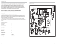
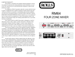
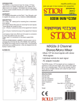
LIMITED WARRANTY
This product is warranted to the original consumer purchaser to be free
from defects in materials and workmanship under normal installation, use and
service for a period of one (1) year from the date of purchase as shown on the
purchaser’s receipt.
The obligation of Rolls Corporation under this warranty shall be limited
to repair or replacement (at our option), during the warranty period of any part
which proves defective in material or workmanship under normal installation,
use and service, provided the product is returned to Rolls Corporation, TRANSPORTATION CHARGES PREPAID. Products returned to us or to an authorized
Service Center must be accompanied by a copy of the purchase receipt. In the
absence of such purchase receipt, the warranty period shall be one (1) year from
the date of manufacture.
This warranty shall be invalid if the product is damaged as a result of
defacement, misuse, abuse, neglect, accident, destruction or alteration of the serial number, improper electrical voltages or currents, repair, alteration or maintenance by any person or party other than our own service facility or an authorized
Service Center, or any use violative of instructions furnished by us.
This one-year warranty is in lieu of all expressed warranties, obligations
or liabilities. ANY IMPLIED WARRANTIES, OBLIGATIONS, OR LIABILITIES, INCLUDING BUT NOT LIMITED TO THE IMPLIED WARRANTIES
OF MERCHANTABILITY AND FITNESS FOR A PARTICULAR PURPOSE,
SHALL BE LIMITED IN DURATION TO THE ONE YEAR DURATION OF
THIS WRITTEN LIMITED WARRANTY. Some states do not allow limitations
on how long an implied warranty lasts, so the above limitation may not apply to
you.
IN NO EVENT SHALL WE BE LIABLE FOR ANY SPECIAL, INCIDENTAL OR CONSEQUENTIAL DAMAGES FOR BREACH OF THIS OR
ANY OTHER WARRANTY, EXPRESSED OR IMPLIED, WHATSOEVER.
Some states do not allow the exclusion or limitation of special, incidental or consequential damages so the above limitation or exclusion may not apply to you.
This warranty gives you specific legal rights, and you may also have other rights
which vary from state to state.
ROLLS CORPORATION
SALT LAKE CITY, UTAH
02/08
MA2152
Mixer / Amplifier
OWNERS MANUAL
2
J2
J3A
RCAX4
RCAX4
J3D
RCAX4
J3C
1
LEFT IN
4
J3B
RCAX4
RIGHT IN
LEFT IN
RIGHT IN
4.99K
XLR F PC
R201
5
R504
10K
5
R206
330
3
2
+12V
5
6
U5B
4560
C502
7
4560
C501
7
27PF
4560
U5A
4
3
2
1
4560
C402
-12V
P4A
P100K X2
U4B
+12V
3
5
6
4
-12V
22K
R207
C401
U4A
P100K X2
P3A
1
P100K X2
P3B
3
8
SW DIP-6
SW 1E
PHAN PWR
R202
4.99K
C202
10U
R205
330
1U C102 R106
330
R102
R107
4.99K
SW 1F
33k
6
7
SW DIP-6
PHAN PWR
P100K X2
P4B
6
R501
10K
R403
10K
6
R401
10K
2
3
C201
10U
3
XLR F PC R101
4.99K
1
2
27PF
27PF
1
1
+12V
U2B
4560
27PF
Q1
2N3904
7
7
R505
47K
R502
47K
R404
47K
R402
47K
+12V
R208
33K
C204
4560
C103
120PF
U1B
.001
C203
27PF
5
6
5
6
+12V
8
8
R7
C5
10U
U1A
4560
1
1
1
C12
503
3
C13
503
R604
10K
6
R601
10K
-12V
-12V
5
6
4560
C601
27PF
1
+12V
C14
503
U9B
4560
R5 & R6 IN 2152 ONLY AND C2 & C3 47UF
-12V
7
J5
JAPDC
C15
503
R606
22K
R603
22K
Text
C602 27PF
P100K X2
P5B
4
3
2
U9A
P100K X2
P5A
1
10
R116
100K
SW DIP-6
SW 1C
DUCK ENABLES
R901 10K
3
DRAW ING FOR REFERENCE ONLY
PRODUCTION UNITS MAY VARY
NOTES
+12V
R607
1K
R10
1K
RCAX4
2
1K
SW 1D
R9
R608
1K
C207
.01 UF
47K
R14
47K
R1
C107
.01 UF
IF YOU ARE COPYING THIS - STOP IT - DO YOUR OW N ENGINEERING
+12V
J4B
LEFT IN
J6
3.5STJK
P100K
P9
C106
.1 UF
4.7K
R111
P100K
P8
.1 UF R211
4.7K
C206
4.7K
R210
R110
4.7K
RIGHT IN
-12V
RCAX4
J4A
4560
U2A
C205
27PF
-12V
Phan Pwr Reg
3
2
P100K
P2
100K
LEVEL
R209
4.7K
LEVEL
3
2
C105
27PF
4
4
LEVEL
P100K
P1
R109
4.7K
C104 120PF
R108
33K
3
2
11
330
R105
2
3
1
3
2
5
6
+12V
1
1
1N400X
-12V
3
P6A
P100K X2
BASS
C805 .047
BASS
C807
.047
MONO
+12V
U11B
4560
R824
1M
R825
22K
R823
33K
SW 1A
SW DIP-6
+12V
-12V
R5
1.1K
C3
1000UF
H1E
HD5
H1D
HD5
7
Q5
H1C
HD5
R822 33K
4
22K
R815
1
47K
R602
7
27PF
H1B
HD5
P7B
P100K X2
5
6
4
4560
U11A
1M
R814
R813
33K
4560
U12B
+12V
-12V
220K
R16
D13
1N4148
C4
7
H1A
HD5
R6
1.1K
33K
R821
6
TREBLE
C808
220PF
R820
22K
P6B
P100K X2
6
47K
R15
10U
R812 -12V
1
3
2
1
5
6
LM358
C904
U3B
33K
P7A
P100K X2 TREBLE
R819
33K
R811
3
C806
220PF
R810
22K
C2
1000UF
1N400X
D1
4560
47K
5
R904 6
47K
7 33K
R809
33K
LM358
R818
U10B
D3
-12V
U10A
47K
4560
-12V
U3A
C902
27PF
+12V
330K
DUCK RECTIFIER
R903
1N4148
D14
DUCK AMP
R808
47K
R605
SW 1B
SW DIP-6
3
C901
.1 UF
2
R902
10K
4
C101
1U
SW DIP-6
SOURCE 3 (1) MONO
1
3
6
9
4
2
5
2
5
2
4
8
4
8
4
5
8
4
1
8
Back Cover
8
Warranty
2
5 and 6
2
Schematics
1
5
8
Specifications
4
4
5
Operation
8
3
2
Connection
3
2
12
Description
4
1
1
1
5
TABLE OF CONTENTS
Introduction
Inspection
Table of Contents
1
INSPECTION
1. Unpack and inspect the MA2152 box and package.
If obvious physical damage is noticed, contact the carrier immediately to make a
damage claim. We suggest saving the shipping carton and packing materials for
safely transporting the unit in the future.
2. Please visit our website at www.rolls.com and click on the Register Your Warranty Here button, or complete the Warranty Registration Card and return it to the
factory.
5
R3 1K
1
R4
1K
Murray, Utah 84107 USA
MIXER BOARD
Document Number:
MA2152_Mixer .SCH
Date: 10-Apr-2007
Rb
MX15
ROLLS CORPORAT ION
R826
22K
5968 S 350 W
C809
503
R213
22K
1N4148
J4C
RCAX4
RECORD OUT
J4D
RCAX4
1N4148 R827
1M
D12
5
R17
1K
1K
R18
-12V
4
C1
27PF
47K
4560
U12A
D11
Size:
Title
J113
Q6
J113
R212
22K
R816
22K
3
2
R2
NOTE: THIS MANUAL ASSUMES THE USER HAS A WORKING KNOWLEDGE OF AUDIO ELECTRONICS, BALANCED AND UNBALANCED CONNECTIONS, AND PROPER SIGNAL LEVEL SETTING.
4
Sheet 1 of 1
Rev:
A
Thank your for your purchase of the Rolls MA2152 Mixer / Amplifier. The MA2152
is a two rack space mixer amplifier designed for restaurants, schools, churches,
clubs etc. The unit provides a compact and efficient way to mix up to three
sources such as AM/FM tuners, CD players, and video players with up to two
microphones. Priority talkover is provided on Microphone Two for paging, and
on Source One for a jukebox, telephone, etc. The power output section may be
connected to 8, or 16 ohm speakers, or a 25V or 70V system.
6
J1
INTRODUCTION
MIXER SECTION
6
SPECIFICATIONS
DESCRIPTION
MIXER
Input Impedance:
Mic:
Max Input Level:
Mic:
Connectors:
Phantom Power:
Max Gain:
Tone Controls:
Noise Floor:
S/N Ratio:
Priority Attenuation:
POWER AMP
Power Output,
Stereo:
600 Ohms XLR balanced
Source: 22K Ohms RCA
Insert:
22K Ohms 1/4” TS unbal.
-14 dBV Mic level Max
Source: 24 dBV
Insert:
24 dBV
2: XLR, 8: Stereo RCA, 3: 1/4” TRS, 1: Stereo 3.5 mm
4: Binding posts
+12 VDC
Mic:
60 dBV
Source: 26 dBV
+/-12 dB 100 Hz Bass
+/-12 dB 11kHz Treble
Speaker out: -67 dBV
Pre Out: -90 dBV
96 dBV
60 dBV
100 Watts RMS/Ch. 4 Ohms (Both channels driven)
70 Watts RMS/Ch. 8 Ohms
Bridged:
200 Watts RMS - 8 Ohms/70V
Output Matching:
4, 8, 16 Ohms, 25V Stereo, 70V Mono
THD:
<.08%, (1 kHz @ 1 Watt)
Outputs:
RCA Record Out, 5-Way binding post Power
Amp Outputs
Power Bandwidth:
60 Hz - 30 kHz, +/- 1 dB
Damping Factor:
> 150
Slew Rate:
100 Volts/microSecond
Phase Shift:
<10 Deg., 20 Hz - 20 kHz
Power:
120 VAC, 60 Hz 2.5A
Size:
19” x 3.5” x 7.5” (48 x 9 x 19 cm)
Weight:
12 lbs (5.5 kg)
FRONT PANEL
Mic 1, 2: Adjust the level of signal from the corresponding Mic Input.
TONE 1, 2: Adjusts the frequency content of the microphone signal in the channel. When the control is turned counter-clockwise, the high frequencies are cut,
when the control is turned clockwise, the low frequencies are cut.
Source 1 - 3: Adjust the volume of input from the RCA Source Inputs.
IN 3: 1/8” (3.5 mm) Input jack - parallels the rear panel Source 3 Input.
Bass: Adjusts the low frequencies of the Source 1 and 2 signals only.
Treble: Adjusts the high frequencies of the Source 1 and 2 signals only.
Left / Right Output: Adjusts that channel’s output level
Right/Left Clip: LEDs indicating clipping in the indicated MA2152 amplifier side.
Protect: Indicates that the amplifier has reached overload, and the MA2152 will
need to be turned off, and restarted.
Power: LED indicating power is applied to the MA2152 and the unit is on.
REAR PANEL
SCHEMATIC
POWER AMP SECTION
IEC Power Input / Fuse Holder: Connects to the enclosed IEC power cable.
Please replace fuse only with recommended rating.
4 - 8 Ohm / 25 Volt Output: The two red banana jacks are used when the
MA2152 is in Bridge/Mono, or 70V mode.
RECORD OUT: Stereo RCA jacks, contains all mixed signals before the Master
Level controls.
SOURCE INPUTS: Stereo RCA jacks, Channels 1 - 3, for connection to stereo
sources such as AM/FM tuners, cassette players, cd players, or video players.
LEFT/RIGHT AMP INSERT: 1/4” Tip-Send, Ring-Return insert jack.
DIP SWITCH: Contains the small switches for engaging Mic 1, 2 phantom power,
Source 3 Stereo or Mono, the priority (Talk Over) functions, and the Mono/Stereo
select.
MICROPHONE ONE and TWO: Balanced XLR inputs to be connected to dynamic or condenser microphones.
BRIDGE SWITCH: This switch selects the output configuration; Bridge Mono, or
Stereo / Dual Mono.
5
2
CONNECTION
Inputs
Connect low impedance microphones to the Mic inputs. If a paging microphone
is being used, connect it to Mic Input 1 so it may be used with the Talk Over
function. Connect source signals such as CD players, cassette players or video
players to the RCA Source Inputs. If a jukebox is being connected, and you want
its signal to mute the other source signals, connect it to Source input 3.
For recording purposes, connect a stereo RCA cable to the Record Out jacks,
and to your recording device.
Amp Inserts
To connect a signal processor to the MA2152 signal(s), use an insert plug, or
cable wired as shown in Fig. 1. This return signal is then sent to the output level
section of the amplifier.
Outputs
In STEREO MODE, the Right speaker is connected to the red and black banana
RIGHT OUTPU connectors. The Left speaker is connected to the red and black
banana LEFT OUTPUT connectors. Impedances should be no less then 4 Ohms.
In BRIDGE MONO MODE, the speakers are connected to the two red BRIDGE
OUTPUT connectors.
Connect the MA2152 to a properly grounded AC outlet. There is a one second
turn-on delay provided to prevent possible speaker damage in case all equipment is on a single power strip.
BRIDGING
To bridge the MA2152 outputs together, first ensure the power is off. Move the
BRIDGE switch to the “Bridge” position, and set the STEREO/MONO DIP Switch
(details on the next page), to MONO. The Channel 1 Volume control will be the
master volume - Channel 2 is inactive. Connect the load (speakers) to the two
positive (red) banana jacks. Make no connections to the black posts. The level
meters will both light, and the output power into 8 Ohms is the sum of the LEDs
that light.
DRIVING 25 OR 70 VOLT LINES
The MA2152 will drive 25 or 70 Volt lines directly with no added transformers
when used the following way:
- Each channel (used individually) will drive 25 Volt lines directly.
- A single 70 Volt line bay be driven when the MA2152 is in Bridged Mode. In
order to drive two 70 Volt lines, two 8 Ohms to 70 Volt conversion transformers
will be needed.
3
OPERATION
DIP SWITCH SETTINGS (From left to right)
• If a microphone requires phantom power, move the Mic channel’s corresponding PHANTOM POWER switch to the on position. This applies 12 volts dc phantom power to the indicated microphone.
• SOURCE 1 MONO; this switch sums the Right and Left inputs of Source 1 to
mixed dual-mono inputs.
• Mic 1 Priority; when in the on position, all program material on Mic 2 and Sources 1 and 2 will be “ducked” or muted when a signal is present at Mic 1. Source 3
is left un-muted.
This function is used for paging.
• Source 3 Priority: when in the on position, Source 1,and 2 will be “ducked” or
muted by the signals at Source 3.
This function is for jukebox priority. With a jukebox connected to Source input 3,
and the Talkover switch 2 on, the other Source input signals such as background
music, will be muted and only the jukebox will be heard.
• MONO / STEREO: When down, the output of the MA2152 is summed to mono.
Either jack can be used as a mono output.
FAULT PROTECTION
The fault protection in the MA2152 limits the current to the output stage. This
mode is entered whenever the output stage is called upon for too much power, it
may also be fooled by impedances lower than four ohms - which may cause the
output stage to overheat and be irreversably damaged.
Since the MA2152 is convection cooled, the unit radiates heat from the front
panel and, depending on the load demand, it may become very hot if drawn upon
heavily.
To Amp Insert
Fig. 1
4