1
Rev.
ORACO
c
SUPERSEDES
8
This manual mniains IMPCIRTYNT
WARNINGS and INSTRUCTIONS
FIEAD AND RETAIN FOR REFERENCE
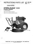
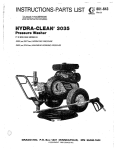
MODEL 800-100 SERIES "A"
2150 psi (150 bad OPERATING PRESSURE
2250 psi 1155 bar1 MAXIMUM WORKING PRESSURE
GRACQ INC. P.Q. Box 1441 MINNEAPOLIS.
@COPYRIGHT 1981 GRACO INC.
MN 55440-1444
-. .
i
Read and Linderstand all
1 Nj E C T 1 3 N {+fi 2A 3 9
ii;sir!.lcticn
rcanui:/s b e f o r e o p e r a t i n g e q u i p m e n t .
~~~~~~~~~~~~~~~~~~~~~~~~~~~~~~~~~~
Fluids underhighpressure
from sprayorleaks
can
penetrate the skin and cause extremely serious injury,
including the need for amputation.
Do not spray flammable liquids. Do not operatethe
engine wherecombustiblefumes
or dustmay
be
present.
NEVER point thespray gun atanyone or any part of the
GAS ENGIME F R E C A U i l O N S S %
body.
NEVER fillfueltankwhile
engineis runningorhot.
Avoidthepossibilityof
spilled fuelcausing
a fire.
Always refuel slowly to avoid spillage.
NEVER put hand or fingers over the spray tip.
NEVER try to stop or deflect leaks with your hand or
NEVER operate engine in a closed building unless the
body.
MEDICAL T R E A T M E N T %-"a *&A&
exhaust is piped outside. The exhaust contains carbon
monoxide, a poisonous, odorless and invisible gas,
which, if breathed, may cause serious illness orpossibly
death.
any
If
NEVER make adjustments on machinery while it is con-
ALWAYS have the tip guard in place when spraying.
fluid appears t o penetrate
your
skin, get
EMERGENCY MEDICAL CARE AT ONCE.
DO NOT TREAT A S A SIMPLE CUT.
Tell thedoctor exactly whatfluid was injected. For
treatment
instructions
have
your
doctor
call the
NATIONAL POISON CENTER NETWORK
(412)681-6669
AVOID COMPONENT RUPTURE
Even after you shutoff thegasoline engine, there is high
pressure in the pump, hose and gun until you release it
by triggering the gun. So before removing the spray tip
or servicing the unit, always shut off the unitand trigger
the gun to release pressure.
nected to the engine: first remove theignition cable
from the spark plug.Turning over themachineryby
hand during adjustingor cleaning mightstart the engine
and machinery, causing serious injury to the operator.
NEVER run the engine with governor disconnected, or
operate at speeds in excess of 3300 RPM load.
Precaution is the bestinsurance against an accident.
When starting.theengine, maintain a safe distance from
moving parts of the equipment.
GENERAL
NEVER run unit with beltguard removed. Keep clear of
system comBe sure that all accessoryitemsand
ponents will withstand the pressure developed. NEVER
exceed the pressure rating of any component in system.
NEVER alter or modifyequipment - yourpersonal
safety, as well as~the function ofthe equipment, is at
stake.
moving parts when unit is running.
Before each use, check hose for weak, worn or damaged conditions caused by traffic, sharp corners, pinching
or kinking. Tighten all fluid connectionssecurely before
each use. Replaceany damaged hose.
Observe detergent manufacturer's safety precautions.
Avoid getting detergent or other liquids in your eyes.
Follow the directionson the container regarding contact
with eyes, nose, and skin, breathing fumes, etc. Always
wear full goggles to protect youreyes from thespray as
well as any debris dislodged by the spray. If necessary,
wear gloves or other protective clothing. If antidotesor
treatment are recommended, be prepared to use them.
Do not use chemicals or agents which are not compatible with Buna-N and PVC orneoprene cover of hose.
DON'T spray toxicchemicals
weed killer.
such as insecticide a r
Do not leave a pressurized unit unattended. Shut off the
unit andrelease pressurebefore leaving. ''
IMPORTANT
United States Government safety standards have been adopted under the Occupational Safety and Health Act. These
standards - particularly the General Standards, Part 1910, and the Construction Standards, Part 1926 - should be consulted in connection with your use of airless spray equipment.
2
801-191
~~
Refer to the engine instruction booklet provided with
the unit.
watersandblaster.
SeeAccessories
andinstruction
manual 801-190 for installation and operation.
Install Wheels and Handle
Slide the axle into the frame. Slide the wheels onto the
axle and secure with the 1/2 inch locknuts provided.
Connect To Water Supply
Attach the handle with the 4 screws, nuts, flat washers
and lockwashers provided.
Install Hose and Spray Gun
Connect the spray hose to the spray gun by inserting
the pin at the end of thehose into the quick disconnect
coupler on the gun. Connect thehose to the fluid outlet
in the same way.
Remove the tape from the cap on top of the pump.
Cleaning Accessories
For spraying detergent or other cleaning solution,
we
recommendusingachemicalinjectorkit.
See Accessories and instruction manual801-192 for installation
and operation.
For removing rust and old paint werecommend using a
CAUTON
Beforeattaching to water supply,check
plumbing
code
regarding
cross-connection
to
water supply.
local
Do not exceed160" F (70" C) watertemperature to
pump in a direct supply system.
Connect a hose with at least a 3/4 in. (19 mm) ID from
your city water supply to the unit's 3/4 in. garden hose
threaded inlet. The supply hose should not be more
than 50 ft. (15 m) long.
NOTE:
For a direct SUDO~V svstem. your water
source at the unct 'must'have a flow rate of
AT LEAST5 GPM (19 LITER/MIN).
If your operating conditions are different from above.
contact
our
Customer
Service.
Department
for
assistance.
801-191
3
Startup
Before startino. be sureto read the safetv warninos and
setup instruct7ons.
I
r
CAUJION
Shut off cleaning unit when notactually spraying,
for longer pump life. The pump will overheat if left
running for over 10 minutes without spraying.
Check the oil and gasoline levels daily
Check the filter screen in the water inlet connection as
often as necessary, at least daily. Do not operate the
unit with the inlet and filter screen removed.
Turn on the water supply.
Trigger the gun to release any back pressure
ltVA 8 I?]IihlG
DO NOT try to adjust the unloader valve or change the
engine speed. Changing these settings may cause excessive
pressure,
intermittent unloader
operation,
wasted fuel and increased wear on parts.
or triaaered oosition.
Set the choke and open the fuel valve.
NOTE:
Foreasier starting, hold the gun trigger open
while pulling the rope.
Put your foot on the frame or wheel to steady the unit
when you'pull thestarter rope. Hold thegun inyour left
hand with the trigger open while starting the engine.
Grasp the starter rope grip and rapidly pull out the cord
(1 m). Repeat if necessary with the
chokeopened slightly. Whenthe engine starts, immediately release theguntrigger.
Open thechoke
gradually.
two or three feet
PUMP MUST NOT BE RUN DRY and must be drained
of water priort o exposure to freezing temperatures.Use
andstorethe
unit where it willnotbesubjected
to
freezing temperatures. If water does freeze in the unit,
thaw before trying to start. A 50% anti-freeze solution
may be pumped prior to cold weather storage.
Use only spraytips that are matched to the unit to avoid
excessive cycling and wear of the unloader valve. See
ACCESSORIES.
CAUTION
pour hot water on a frozenpump.
A sudden
temperature
change
may
crack the ceramic
plungers.
Never run the cleaning unit dry. Costly damage to
the pump willresult. Always be sure water supply
operating.
I is completely
C
A turned
U on before
T
I
O
N
1
Do not pump caustic materials.
Inspect
all
connections
for
.any
necessary.
Avoid dragging hose over an abrasive surface~suchas
cement. This causes excessive wear and shorter hose
life.
leaks. Tighten if
Cleaning
For Hvdra-Clean technique, see the Chemical lnjectnr
)2.
For abrasive
cleaning,
manual. 801-190.
see the
Water
Sandblaster
Follow these precautions when removing and installing nozzles:
Clean the intake line strainer daily.
Lubrication and Care
Change the engine oil after every 100 hours of operation. Drain oilwith enginewarm. Engine requires 1
quart (0.96 liters) 30W oil. Seeseparate instruction
manual for maintenance procedures.
Fill pump crankcase to dot on oil gauge window with
25 oz. (0.75 liters) of crankcase oil (part no.801-1441 or
1.
Shut off the cleaning unit and trigger the gun
to relieve pressure. Engage the trigger safety.
2.
Keep the nozzle andthetubepointedaway
from you and everyone else.
3.
Do not put your hand over the tip to push the
nozzle into place. Grasp it from the side and
keep your fingers away from the tip.
NEVER alter adjustment o
valve.
4.
Do not let anyone else touch the spray valve
while you are cleaning nozzles.
Altering or adjustingunloader
performance of unit.
5.
Be sure the slip ring is pushed forward to lock
the nozzle in place before triggering thespray
gun.
S h u t d o w n a n d Care Of Unit
When unit is not in use, turn off water supply,
When shutting down for the day or weekend, shut off
unit, shut off watersupply valve, andtrigger gun to
release pressure. Wipe off the unit with a damp rag.
4
Before extended storage, flush the pump with light oil.
801.191
~~
equivalent SAE 40 weight hydraulic oil with antiwear
and rust inhibitor additives.
Change initial fill after 50
hour running period. Change oil every 3 months or at
500 hour intervals.
will not increase
Service of the unloader must be performed only
IOUBLESHOOTING
PROBLEM
CAUSE
SOLUTION
Engine Will Not Start
3r Hard To Start.
No gasoline in fuel tank or
carburetor.
Fill the tank with gasoline, open fuel shut-off
valve.
Check fuel line and carburetor.
Water in gasoline or old fuel.
Drain fuel tank and carburetor. Use new fuel
and dry spark plug.
Choked improperly. Flooded
engine.
Open choke and crank engine several times to
clear out the gas.
Dirty carburetor air filter
Remove and clean.
Spark plug dirty or improper
gap.
Clean, adjust the gap or replace.
Spray gun closed.
Trigger spray gun.
Partially plugged air filter.
Remove and clean.
Spark plug dirty, wrong gap,
or wrong type.
Clean, adjust the gap, or replace.
Incorrect ignition timing.
Time engine.
Worn nozzle.
Replace with nozzle of proper size.
Belt slippage.
Tighten or replace; use correct belts and replace
both a t same time.
Air leak in inlet plumbing.
Disassemble, reseal, and reassemble.
ingine Misses Or Lacks
’ower
-ow Pressure
Relief valve stuck, partially plug- Clean, and adjust relief valve: check for worn
and dirty valve seats. Kit available.
ged or improperly adjusted;
valve seat worn.
Inlet suction strainer clogged or
improper size.
Clean. Use adequate size. Check more
frequently.
Worn packing. Abrasives in
pumped fluid or severe cavitation. Inadequate water supply.
Install proper filter. Check flow available to
pump.
Fouled or dirty inlet or discharge
galves.
Clean inlet and discharge valve assemblies.
Worn inlet or discharge valves.
Leaky discharge hose
Replace worn va1ves;valve
discharge hose.
Restricted inlet or air entering
the inlet plumbing.
Proper size inlet plumbing; check for air tight
seal.
Inlet restrictions and/or air
leaks. Stuck inlet or discharge
valve.
Leaking H.P. seals.
Clean out foreign material, replace worn valves.
Replace seals.
Nater leakage from under
he manifold.
Worn packing.
lnsrall new packing.
Nater in pump crankcase.
Change oil at 3 month or 500 Hour intervals usMay be caused by humid air
zondensing into water inside the ing Graco Crankcase Oil (other approved oil
every month or 200 hours) P.N. 801-144.
crankcase.
’ump runs extremely rough,
~ressure low.
seats and/or
801-191
5
PROBLEM
CAUSE
SOLUTION
Frequent or premature failur
of the packing.
Scored plungers.
Replace plungers.
Over pressure to inlet manifold.
Reduce inlet pressure
Damaged or worn plungers.
Replace plungers.
Abrasive material in the fluid be
ing pumped.
Install proper filtration on pump inlet plumbing.
Excessive pressure and/or
temperature of fluid being
pumped.
:heck pressures and fluid inlet temperature; be
jure they are within specified range.
Over pressure of pumps.
3educe pressure.
Running pump dry.
l o not run pump without water.
Foreign particles in the inlet or
discharge valve, or worn inlet
and/or discharge valves.
:heck for smooth lap surfaces on inlet 2nd
h h a r g e valve seats. Discharge valve seats and
nlet valve seats may be lapped on a very fine oil
stone.
Strong surging a t the inlet
and low pressure on the
discharge side.
NOTE:
A M11andM30metricwrenches
are re-
quired for servicing pump.
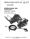
PUMP
Valves
Photo 1 and 2.
1) Remove the hex d u o usino an M30’wrench
2 ) Examine O-ring uide; plug &d replace if evidence of
cuts or distortion.
3) Removevalve assembly including retainer, spring,
valve and valve seat from valve cavity.
NOTE: Valve assembly maycome
apart during
removal.
4) Replacevalveparts
with service kit(80-041) including retainer, spring, valve, valve seat, O-ring and
back-up-ring.
5) Replace valve cover andtorque to75 ft-lb (100 N.m).
Pumping Section
Photo 3.
1) Remove the four (4) hex nuts from the manifold.
2 ) Separate the manifold from the crankcase.
NOTE: It may be necessary to tap manifold lightly
with mallet to loosen.
CAUTION:
plungerswhenremoving
either plungers or seals.
to avoid damage to
3) Carefully examine each plunger for any scoring and
replace if necessary.
Plungers
Photo 4.
1) UsinganM11wrench,remove
the plunger retainer.
2) Slide outthe seal retainer with
oil
wick
and
rubber
barrier
slinger.
31 With aslight twistingmotion,
loosen
the
plunger
fromthe
plunger rod and remove
NOTE: Thestudmayremain
with the retainer when
removed. Disassemble
and
screw
stud
into
plunger
rod
fingertight.
41 Replace O-ring and back up ring
on plunger retainer.
51 Saturatenewoilwick
by soaking in oil.
6) Installnewplunger.
71 Replace plunger
retainer
and
torque to 80 in-lb (9 N.m).
81 Installnewoilwickin
sealretainer.
9) Replace barrier slinger over new
plunger.
101 Lubricate each plunger sleeve
and carefully slide manifold onto
crankcase.
Seals or V-Packings
Photo 5,6,7and 8.
11 RemoveC-ring from sealcase.
2) Thenremovethe
low pressure
seal from the seal case.
8
3) Unscrew the seal case from the
manifold using a special key
wrench (801-044):
0
Removethehigh pressureseal
and examine. Before replacing,
lubricateIDand
OD ofnew
highpressure seal and press into
manifold.
NOTE: A socketandextension may beused
pressure
seal
from
~. manifold.
to
Install new O-ring on sealcase
and lubricate OD-of O-ring.
Screw seal case into manifold.
Lubricate ID and OD oflow
pressure seal and press into seal
case.
Replace
C-ring
holding
low
pressure seal in place.
V
9) Lubricateeachplunger
sleeve
and carefully slide manifoldonto
crankcase.
NOTE: When
replacing
manifold onto plungers, extremecautionshould
beexercised toavoid
damage to the seals.
10)Torque all four (4) boltsto
in-lb (27N.m).
240
NOTE: Carefully
study
the
order
of
respective
parts
and
note positionof seals to
assure proper reassembly
and operation.
65
SERVICE
TOOLS
KEY WRENCH 801-M4
EXTRACTOR TOOL 801-205
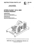
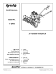
PARTS LIST
R EP
FA R T
NO
1
3
4
5
6
7
8
9
10
11
12
13
14
15
16
17
18
19
20
21
22
DESCRIPTION
QN
NO.
801"x)
801-003
801 -004
801
-005
801.008
801-012
801-013
800-015
801-235
801-128
801-017
801-018
801-019
801-020
801-021
801-022
801-ow
801
-024
801-025
801-026
801-001
33
34
35
36
37
33
39
40
41
42
801-027
801-028
801-267
'801-030
'801-031
'801-032
'801-033
'801-034
'801-035
'801-036
'801-037
'801.038
'801-03s
-801-040
CAP
. O-RING
DISCHARGE MANIFOLD
.WASHER
. SEAL
, RETAINER
.WASHER
.WICK
. RING, retaining
. PLUNGER
. STUD
. RING, backup
. O-RING
. RETAINER,plunger
801-084
UNLOADER ASSY,
Includes items 38-64
801
-045. CAGE,valve
801-046 . O-RING
80N"
SPRING
801"
. BALL
801-049 . SEAT
. O-RING
. UNLOAOER
. TAG
. GASKET
. HOUSING
. CYLINDER
. GASKET
. PLUG
. HOUSING, valve
. SPRING
43
801-050
44
45
52
800-012
801.143
1
55
2
2
1
1
1
2
2
2
5
15
6
11
4
1
1
1
3
3
3
3
3
3
3
3
1
1
1
1
1
2
1
1
1
DESCRIPTION
1
2
1
1
1
3
1
23
24
25
26
27
28
29
30
31
32
REF PART
NO. NO.
53
54
56
61
62
63
64
65
f.
801-060
801-061
801-062
801-063
801-068
801-069
801-070
801-071
800-101
ON
2
1
1
1
1
1
1
2
1
1
VALVF
SEnT-
1
1
*".._
1
1
HOSE AND GUN ASSY. see aun detail
fn. n n n c
E6
67
68
69
70
72
73
74
75
78
79
n
80
81
82
83
e4
85
86
87
ea
a9
90
91
92
93
801.085
COVER, belt guard
801-086 BASE. belt guard
801-081'
SCREW, mach. sloned. 1/4 -20
x 1-3/4"
801-088 SCREW, mach. crossrecessed. 5/16-18x
l-l/7'
'801-090
COGPLER. male quick disconnect
801-105 NIPPLE, straight. brass. 1/2 not x 3-1/2"
801-106 TEE,brass. 172 kpt
801
-236NIPPLE, hex. steel, 1/2 x 3/8 npt
801-108 NIPPLE, hex,brass, 1/4 x 1/2 npt
76
801-1m
PLUG, hex. brass. 3/8 npt
801-110 ADAPTER. 1/2" garden hose
801-111 NUT, brass.gardenhoseadapter
801-112 SCREEN, inlet. 1/2"
801-113 HOSE, cpld 1/2 nptlrnbel. 17.1/T' Ig
801.081
SCREW, mach. hex hd; M80 x 20 mm
801-082
SCREW, mach, hex hd: M6 x 30 mrn
801-129 LABEL, warning
801-130 LABEL.warning
801-131 PLATE, serial
801-132 RIVET
801-135 HUB
801-136 KEY, pulley
801-137 KEY, pulley
801-133 CHASSIS
801-139 LOCKWASHER, 1/4"
801-140 LABEL. identification
801.141
LABEL, warning
1
1
4
1
1
1
1
1
1
1
1
1
1
2
4
1
1
1
2
1
1
1
1
4
1
1
"Recommended"toolbox"
spare parts.Keep on hand to
reduce down time.
'*Included in repair k i t
Order partsby name and number.Alwaysgivethemodel
number and series /ewer of rhe assembly for which you are
ordering.
801-191
9
19
28
f3
14
L 1 9
5
15
A
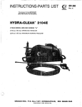
Repair Kit 801-083
Includes items A, 6, C . D, E and F
REF
NO.
PART
NO.
DESCRIPTION
801-007
SPRAY
HOSE,
3/8" ID, 50 ft.
(15 ml lg
2
800-017
SPRAY
GUN,
(replaceable
parts
SERVICE
3-16) items include
3
801-244 . HANDLE, left
1. Remove the 8 screws from the body halves (3) and
801-245 . HANDLE, right
4
(4). See the Parts Drawing.Separate
the body
801-249 . SPRING
5
801-254 . LEVER
6
halves.
801-256 . NEEDLE
7
2. Remove the plug (141. spring (5)and ball (AIfrom
8
801-262 . HEX
PLUG
9
801-261 . DISCHARGE FlTlNG
the valve body IG).
801-247
10
. VALVE
BODY
801-253 12
11
SLEEVE
. GUIDE
3. Remove the snap ring (61. Then
remove
the
valve
801-246 , TUBE
801-26313
FITTING
. INLET
seat IC1 and O-ring (Dl.
801-250
14
. CAP
4. Remove the sleeve nut (11) and O-ring (E) with the
. SCREW
801.264
15
(F).
801-265
16
. SCREW
rod
actuator
32"
801.134
17
TUBE.
5. After installingthe new seat (Cl and ball (A), tap the
18
801-029
GRIP
a proper
seating
19
801-009
COUPLER,
female
quick
disconnect
ball
lightly with a hammer to assure
20
'801-090
COUPLER,
male
quick
disconnect
between the ball and seat.
nozzle
HOUSING,
801-073
21
blasting;
22 TIP,'801-010
0"
6. Reassemble in reverse
order,
using
the
remaining
23
.801.011
TIP, cleaning;
150
new parts from the repair kit.
24
GUARD,
801-074
tip
PLATE, warning
801-07625
801-07726
RIVET
801-103
27 NIPPLE,
hex;
1/4
x 3/8" npt; brass
'801-091
28 COUPLER,
male
quick
disconnect
2
QTY
1
1
.
1
1
1
1
1
1
1
1
1
1
1
1
1
7
1
1
1
31.
2
1
1
2
1
2
1
Order parts by name and series letrer of the. assembly for
which you are ordering.
'Recommended "tool box" spare parts.
10
801-191
CHEMICAL
INJECTOR
KIT
800-102
For injecting harsh cleaning chemicals downstream
CHECK VALVE 801-133
Prevent back up of contaminated water into fresh
supply. Install upstream from pump.
from pump.
WATER SANDBLASTER 8W-103
For abrasive cleaning of stubborn dirt and paint
TECHNICAL DATA
ENGINE: HONDA MODEL G4000B6
4 cycle. single cylinder, air
cooled, 10 hp.
GASOLINE TANK: 1.58 gallon 16 liter1
capacity
WATER PUMP: 2150 PSI'1150bar1 max.
pressure: 4 GPM
115 iiter/minl.
WETTED PARTS: Stainiess Steel, Aluminum,
Phenolic Plastic, Ceramic
Liners. Nitrile Rubber.
WEIGHT:180 Ib 175 kgllnot including gasoline and motor
oill.
OVERALL DIMENSION: Length: 32' 1810 mml
Width: 28" 1710 mml
Height: 25.5' 1650 mml
MAX. WATER TEMPERATURE:
INLET HOSECONNECTION:
1W"170' CI
3/4" garden hose If1
THE GRACO WARRANTY
Graco Inc. warrants all equipment manufactured by it and bearing its name to be free from defects in
material and workmanship under normal use and service. This warranty extends to the original purchaser
for a period of 12 months fromthe date of purchase and applies only when the equipment is installed and
operated in accordance with writtenfactory recommendations. This warranty does not cover damage or
wear which, in the reasonable judgment of Graco. arises from misuse. abrasion.'corrosion. negligence.
accident, substitution of non-Graca parts, faulty installation or tampering.
This warranty is conditioned upon the prepaid return of the equipment claimed to be defective for
examination by Graco to verily the claimed defect. If the claimed defect is verified. Graco will repair or
replace free of charge. any defective parts. The equipment will be returned to the original purchaser
transportation prepaid. If inspection of the equipment does not disclose any defect in workmanship or
material. repairs will be made at a reasonable charge and return transportation will be charged.
THIS LlMiTED WARRANTY IS EXCLUSIVE, AND IS IN LIEU OF ANYOTHER
WARRANTIES
IEXPRESS OR IMPLIED) INCLUDING WARRANTY OF MERCHANTABILITY OR WARRANTY OF
FITNESS FOR A PARTICULAR PURPOSE AND OF ANY NON-CONTRACTUAL LiABlLlTlES
INCLUDING PRODUCT LlABlLlTiES BASED ON NEGLIGENCE OR STRiCT LIABILITY. EVERY FORM
OF LiABiLlTY FORDIRECT,SPECIAL OR CONSEQUENTIAL DAMAGES OR LOSS IS EXPRESSLY
EXCLUDED AND DENIED.
EQUIPMENT NOT COVERED BY GRACO WARRANTY. Accessories or components 01 equipment sold
by Graco that are not manufactured by Graco lsuch as electric motors. switches, hose, etc.1 are subject
to the warranty. if any. of their manufacturer. Graco will provide purchaser with reasonable assistance in
making such claims.
Factocy Branches: Atlanta, Dallas, Detroit. Los Angeles, West Caldweil IN.J.1
Subsidiary and Affiliate Companies: Canada: England: Switzerland: France: Germany: Hong Kong: Japan
GRACO INC.
P.O. BOX 1441
MINNEAPOLIS, MN 55440-1444
PRINTED IN U.S.A. 801-191 481 Revised 2-82
45-1[1305 c