1
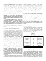
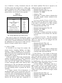
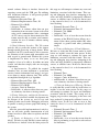
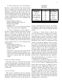
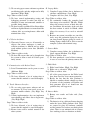
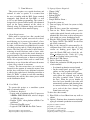
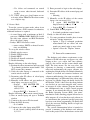
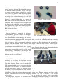
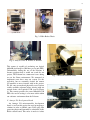
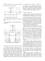
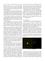
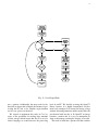
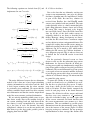
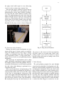
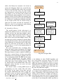
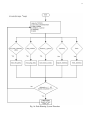
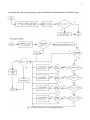
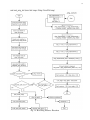
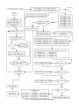
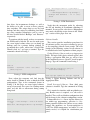
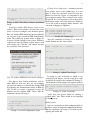
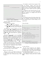
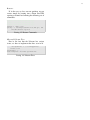
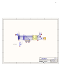
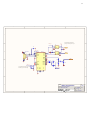
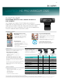
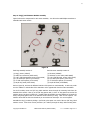
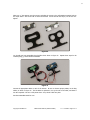
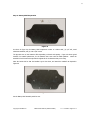
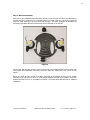
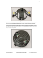
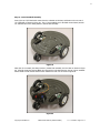
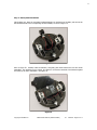
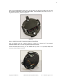
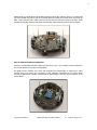
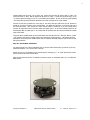
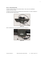
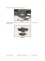
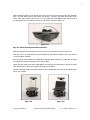
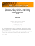
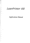
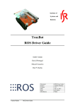
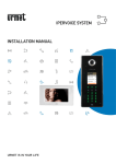
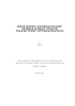
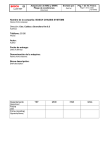
15
describe all of the main hardware components, including interconnection diagrams and a system connection overview depicting the relationship between
our hardware features and ROS. Second, each type
of software program being used will be covered.
This includes an overview of the external programs
interfacing with ROS and associated flowcharts, and
an in-depth look at the relationship of each ROS
node used and the topics associated with each node.
It must be mentioned that there are aspects of
ROS which we do not fully understand due to its
complexity. ROS is an open source program that
has tutorials that enable the user to implement the
code without being bogged down with the program’s
details.Therefore, processes happening internal to
ROS will not be covered.
VII. B REAKDOWN OF H ARDWARE S UBSYSTEMS
Our core hardware is comprised of: A laptop,
a Parallax Eddie robot, an Atmega 328 microcontroller, five ping/IR sensors and a camera. Eddie
is a differential drive robot comprised of a microcontroller containing an integrated PID, two optical
wheel encoders, two PWM driven motors and two
lead acid batteries. Eddie is programmed to directly
interface with the ping/IR sensors however, our
SLAM algorithm could ideally interface with any
robot platform that was differential drive. Keeping
this in mind, we chose to use an Atmega328 microcontroller to control the ping/IR sensors, which
allowed ROS to communicate only encoder data
with Eddie. The assembled Laboratory Prototype
hardware can be seen in Figure 2.
A. Encoders
Initially, Eddie was driven by a GO command
which uses a set velocity for travel but does not
give feedback as to how far the robot has traveled
or in which direction. When we tried to use the GO
SPD command, which uses the wheel encoders for
movement, it did not work. We contacted Parallax
and with some factory support, we managed to get
an alternate set of less accurate 32 tick encoders
to work without learning why our original encoders
failed. Figure 3 shows the replacement encoders and
Figure 4 shows Francisco hard at work debugging
encoder data.
As our project progressed, we needed to use
the original wheel encoders for their accuracy so,
Fig. 3: 32 tick encoders
Fig. 4: Troubleshooting 32 tick encoders
after a second trip to Parallax and some extensive
troubleshooting, we found that one of our original
encoders was bad, which caused the original issue.
Figure 5 shows the new encoders. Thanks to Parallax’s help, we were able to get our project back on
track. Figure 6 shows the team after troubleshooting
the encoder issues with Parallax.
Fig. 5: Motors with 144 tick encoders
B. Camera
In order to process the vision data, we need a
vision sensor. Because webcams are cheap, readily
available, and easy to interface, it was decided
to use one for this project’s vision sensor. After
looking at recommended options, the team decided
on the Microsoft Lifecam Studio as seen in 7.