1
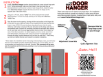
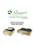
Model 600 Installation Instructions & Owners Manual 1
• Center Hung
• Flush
Automatic Door Operator
$20
Erich Industries, Inc.
Performance Products Division
550 N. Nine Mound Road
Verona, WI 53593
U.S. Patent #4365-442
U.S. Patent #6138-412
Other Patents Pending
Misc. U.S. Trademarks
• Parts
• Technical
• Sales
• Support
SwingDoorOpeners.com
- WARNING As with any mechanized equipment, do not install, operate or service this product unless you have
read and understand the safety section, warnings, installation and operating instructions contained in
this manual. Failure to do so could result in property damage, bodily injury or even death.
CHASE Industries, Inc.
10021 Commerce Park Drive • Cincinnati, Ohio 45246
1-800-882-5839
(513) 860-5565 • (800) 543-4455 • Fax (800)
245-7045
Technical Support (800) 305-6736
2/1/13
P/N 15099.00
Contents
2
Page
Section 1
Product Description
Section 2
Safety - READ BEFORE OPERATING OPENERS!
Section 3
Installation
Section 4
Operation
Section 5
Maintenance
Section 6
Troubleshooting
Section 7
Parts List & Exploded View
Section 8
Electrical Wiring & Circuit Board User's Manual
30 - 38
Section 9
Options
39 - 44
Section 10
Instruction Sheets / Drawings
45 - 62
3-4
5
8 - 24
Cam-Rise Center Hung Doors -New Construction - 8
Door Mount
Header Mount
Cam-Rise Center Hung Doors -Retrofit - 12
Flush Infitting Doors - 20
Door Mount
Header Mount
25
26
27 - 28
29
Doorstop Installation - Head Mounted - Center Hung Doors Only
Floor Mounted - All Doors
Basic Component Orientation & Hole Patterns
Closer Shim Tube Installation - Center Hung Doors
LCN 4011 Closer Component Installation
No-Rise Conversion Kit Installation Instructions
Filler Tube Sizing for Cam-Lift to No-Rise Hinge Conversion
Double Acting (Center Hung) Doors: Jamb & Head Construction
Details 1, 2, 3, & 4
Cam-Lift Double Acting Doors Converted to No-Rise Single
Action with Opener
Section 1 - Model 600 Description
Application
The 600 series door operator is a surface mounted pneumatic door opener. It is used for
swing doors in Industrial, Institutional and Commercial applications. It is compatible with virtually all types
of interior and exterior doors. Door panels from 2’-6” to 5’-0” wide and weighing up to 600 pounds can
be accomodated. One way, two way and two way bi-parting traffic patterns can be used by varying
combinations of activators and orientations of actuators. Simultaneous operation of double
doors is standard.
Description
The 600 series operator applies opening force to the door header by a pneumatic cylinder, actuator arm
and a rubber wheel. There are only three minimally wearing bearing points for long life and there are no
gears, clutches or motors required. The operator is not attached to the door so it can be operated manually
with complete means of egress at any time, without any harm to the opener mechanism. A standard pull
side door closer provides the closing portion of the cycle. Automatic operation is obtained through a wide
number of activation devices. Because of the operator Ultra-Force™ bracket configuration and pneumatic
system there is little risk of damage if the doors are activated and then struck with a load, or activated
while the doors are locked or blocked in the open or closed positions.
Operation
Automatic door operation is accomplished when the open or initiate command is transmitted from the
activation device to the control enclosure. A wide variety of devices can be used to activate the doors
including: wall switches, floor mats, motion or proximity sensors, touchless switches, infrared beams, remote
radio control, or any device that switches using dry contacts. A microprocessor based control board
controls the hold open time and functionality of the doors. Hold open times can be set from 1-99 seconds
by means of the control board, and opening times can be adjusted from 1.5 to 5 seconds by changing air
regulator pressure and air flow controls.
Mounting
The 600 series can be easily mounted to any conventional door frame header and the face of
the door. Reinforcement of hollow metal jams may be required. Special reinforcing plates are available.
Installation and service should be conducted by qualified personnel. Technical support is available
by calling the factory at 1-800-305-6736.
Control Enclosure
The control enclosure is microprocessor based to insure maximun reliability and flexibility for the end user.
The system has been designed to be easy to set up and operate. The control unit is designed to be connected to a constant power source of 110VAC 60HZ or 230VAC 50HZ, which powers the control
enclosure and a wide variety of activation devices with 24VAC power. The control enclosure can be
mounted up to 25 feet away from the operators (consult factory for greater distances). The only connection
between the control enclosure and the operators is two flexible 1/4” diameter air lines. Air supply to the
control enclosure is accomplished through a single 1/4” or 3/8” air line.
Security
Connecting to security devices such as electric strikes, electromagnetic locks, card readers, keyed
switches, time locks and push button key pads is easily accomplished. Consult factory to determine appropriate
control panel configuration.
.
Consistant with our policy of continued product improvement and innovation, we
reserve the right to change product specifications without notice or obligation.
Center Hung Mounting Shown
Section 1 - Product Description
4
5
Section 3 - Installation
Erich Industries
RECOMMENDED
FOR MOST
APPLICATIONS!
Additional bracket
required for this option
Additional bracket
required for this option
6
7
Center Hung, New Construction
8
Section 3A - Center Hung, New Construction
Section 3A - Center Hung, New Construction
9
WARNING - Improper or
inadequate installation could
result in premature product
wear or failure and could then
cause property damage,
bodily injury or even death.
10
Section 3A - Center Hung, New Construction
Wire activating and safety
sensors into control panel
following wiring details in section
8 and following sensor
manufacturers directions.
Section 3A - Center Hung, New Construction
Adjust opening speed with Air Pressure Regulator. Pull knob "out" to adjust, then push knob
"in" to lock in adjustment. Factory setting is 45 PSI. NEVER adjust beyond 85 PSI or any
setting that is safe! Door speed will vary depending on weight of door and any air pressures.
TIP - If you're
opening a
single door use
the supplied
plug to cap one
of the "OPEN"
air ports.
REMINDER - Don't forget to
mount the "CAUTION Automatic
Door" stickers on the door(s)!
11
12
Center Hung, Retrofit
Section 3B - Center Hung, Retrofit
Cam-Rise Center Hung Doors - Retofit
13
Section 3B - Center Hung, Retrofit
14
DDINST13
Cam-Rise Center Hung Doors - Retofit
DDINST14p
15
Section 3B - Center Hung, Retrofit
Section 3B - Center Hung, Retrofit
16
DDINST14p
17
Section 3B - Center Hung, Retrofit
Wire Activating and safety
sensors into control panel
following wiring details in
section 8 and following sensor
manufacturers directions.
Section 3B - Center Hung, Retrofit
18
Section 3B - Center Hung, Retrofit
Adjust opening speed with Air Pressure Regulator. Pull knob "out" to adjust, then push knob "in"
to lock in adjustment. Factory setting is 45 PSI. NEVER adjust beyond 85 PSI or any setting that
is safe! Door speed will vary depending on weight of door and any air pressures.
TIP - If you're
opening a
single door use
the supplied
plug to cap one
of the "OPEN"
air ports.
REMINDER - Don't forget to
mount the "CAUTION Automatic
Door" stickers on the door(s)!
19
20
Flush or Infitting
Section 3C - Flush or Infitting
See drawings DD-9028 and DD9029 in section 10 of this manual
for more jamb mount details.
21
22
Section 3C - Flush or Infitting
WARNING - Improper or
inadequate installation could
result in premature product
wear or failure and could then
cause property damage,
bodily injury or even death.
23
Section 3C - Flush or Infitting
Wire activating and
safety sensors into
control panel following
wiring details in section
8 and following sensor
manufacturers
directions.
Section 3C - Flush or Infitting
Adjust opening speed with Air Pressure Regulator. Pull knob "out" to adjust, then push knob
"in" to lock in adjustment. Factory setting is 45 PSI. NEVER adjust beyond 85 PSI or any
setting that is safe! Door speed will vary depending on weight of door and any air pressures.
TIP - If you're
opening a
single door use
the supplied
plug to cap one
of the "OPEN"
air ports.
REMINDER - Don't forget to
mount the "CAUTION Automatic
Door" stickers on the door(s)!
24
Section 4 - Operation
25
Erich Industries, Inc.
Performance Products Division
Erich
Industries
550
N. Nine
Mound Road
Verona, WI 53593
Performance
Products Division Phone 800/305-6736
550 N. Nine Mound Road
1-800-882-5839
Verona, WI 53593
OPERATING PROCEDURES FOR OPENERS
A)
Start-up (refer to installation instructions for details)
1. Make sure air lines have been purged (blown free of particles in air line) prior to supply line
hook-up to control enclosure. Attach supply line to control enclosure.
2. Plug in cord or hard wire to electric (110 volt) sources in accordance with local codes.
3. Depress ON-OFF switch to turn on.
4. Set activating devices to owner’s requirements.
5. Adjust opening speed with air pressure control knob in control enclosure. Never lower more
than 40 PSI or raise higher than 85 PSI.
6. Door should not slam open or closed. If this occurs, increase the back check on the door
closer to a cushioned stop at the end of the cycle. Adjust the latch check on the closer for a
cushioned close at the end of the closing cycle.
B)
Operation
1. Depress ON-OFF switch to activate door operator and turn on.
2. Release ON-OFF switch to de-activate door operator and turn off.
3. All activating devices must be plugged into control enclosure to function.
4. Operators will not be damaged if held in closed or open position while activated for an extended period of time.
C)
Emergency Operation
1. In case of a power outage or if turned off, the doors will open and close manually. The operator will not be damaged when operated manually.
2. Always turn operators off during a power outage and turn on when power is restored.
D)
Shutdown
1. Use ON-OFF switch on the control enclosure to de-activate the operator. Turn off.
WARNING - Be sure all safety devices and
activators are working properly before putting
openers into service. If you are having any problem
with these devices, turn off the opener and contact
the manufacturer of the sensor or Erich Industries.
Section 5 - Maintenance
Erich Industries, Inc.
Performance Products Division
550 Erich
N. Nine Industries
Mound Road
Verona, WI 53593
Performance
Products Division Phone 800/305-6736
1-800-882-5839
550 N. Nine Mound Road
Verona, WI 53593
MAINTENANCE
PROCEDURES
MAINTENANCE
PROCEDURES
FOR “KWIK-OP”
A)
B)
Maintenance - Air Source (as applicable)
1. Service compressors, filters, etc. as per manufacturer’s instructions.
2. Service should be carried out in 3 month intervals, or as required. Consult this manual for
details.
Maintenance - Operators
1. Manually open doors to check for “free swing”. Adjust and/or lubricate hinges.
2. Check actuator arms for excessive play. If required, loosen set screw or lock nut and tighten
bolt to remove play. Do not over tighten, which will cause binding. After tightening set screw
or lock nut, check again to insure that the unit has free action.
3. Check cylinder jamb nut and tighten (if required) with the cylinder vent on the bottom.
4. Lubricate bearing points with spray lube.
5. Check air filter on supply air line. Clean, drain, or replace as required.
6. Check, air hoses and connections for leaks, kinks, or contact with moving parts. Correct as
required.
7. Check air pressure and opening speed. Adjust per instructions as required.
8. Check closer back check, closing speed, and latch speed. Adjust per instructions as required.
9. Check Time Delay period. Adjust per instructions as required.
10. Service should be carried out in 3 month intervals along with compressor servicing, or as required.
TIP: As you would with all delicate instruments
and tools, preserve your openers finish by
maintaining the protective oil coating on all
metal bracket components.
26
Section 6 - Troubleshooting
27
Erich Industries, Inc.
Performance
Products Division
Erich Industries
550 N. Nine Mound Road
Performance Products Division
Verona, WI 53593
Phone 800/305-6736
1-800-882-5839
550 N. Nine Mound Road
Verona, WI 53593
TROUBLESHOOTING
1. Unit Will Not Actuate
a. Check for physical jamming or binding of door.
(A minimum 1/16” gap must exist between the floor and the bottom seal of the door.)
b. See if door will open using the HOLD OPEN switch on the control enclosure.
If it does work, go to (d) of these instructions.
The problem is with input devices or control circuit board.
c. Door does not open when using the HOLD OPEN switch mounted on the control enclosure:
problem is either with air supply or power supply.
Open control enclosure and read gauge pressure.
If open/close pressure is at least 30/20 PSI
air supply is OK.
If any lights are lit on the control circuit board
the problem may be a faulty soleniod.
If circuit board lights are all off
the problem may be loss of electrical power.
Make sure the electrical outlet feeding the control enclosure is working.
If it is
the problem may be a faulty transformer.
d. Door opens when using HOLD OPEN switch, but does not respond to other open signals.
Remove cover from control enclosure and observe the display on the control circuit board.
It should be lit. If it is not
replace the control unit board.
e. Observe the status lights in the upper left corner of the control circuit board.
The 2nd light from the left should light when any initiate signal is active (such as a sensing motion detector).
If this light does not indicate activity
most likely a faulty sensor device.
2. Door Opens But Will Not Close
a. Check for binding of actuator arm and cylinder.
Check for free movement of the door.
b. Position of Safety Zone Sensor may cause it to “see” the door.
c. Program function may be incorrect.
(Refer to programming instructions in section 8 of this manual.)
Section 6 - Troubleshooting
Continued...
3. Unit Actuates, Opens Door Correctly, Door Closes Slowly But Not Completely
a. Check for free movement of door and action of door closer.
Check sweep and latch adjustment of close.
Increase door closer spring pressure if required (with corresponding adjustment of air pressure and
opening speed as necessary).
b. Check for free movement of actuator arm and cylinder.
c. Check for release of exhaust pressure at solenoid by loosening the hose fitting at the solenoid.
4. Door Action Too Fast, Unable To Control
a. Reduce air pressure to 40 PSI on air regulator and reset LCN hydraulic door closer backcheck
using backcheck adjustment screw (see instructions included with hydraulic door closer). Then
gradually increase air pressure (opening speed) to achieve full opening without “overswing” while
making minor adjustments to the backcheck screw.
Note: The hydraulic door closer is used to cushion the stopping action of the door.
WARNING - Be sure all safety devices and
activators are working properly before putting
openers into service. If you are having any problem
with these devices, turn off the opener and contact
the manufacturer of the sensor or Erich Industries.
28
Erich Industries, Inc.
Performance Products Division
Order Parts online at:
www.ErichIndustries.com
or call (800)882-5839
29
30
TIP: If you need to
replace or upgrade
your door sensor, find
it at DoorSensors.com
E-2005 (MS microStar) Motion Detector
Red
White
Brown
Black
E-2020 (BEA Eagle) Motion Detector
#1 to H
#2 to N
#3 to N
#4 to I
TIP: If you need to
replace or upgrade your
door sensor, find it at
DoorSensors.com
32
Erich Industries, Inc.
Performance Products Division
Automatic Door Opener
Erich Industries, Inc.
33
Erich Industries, Inc.
NOTE: Most functions are pre-programmed at
the factory so no adjustments may be required
here. Utilize this section for future reference.
34
35
Erich Industries, Inc.
36
(F)
38
38
39
Section 9 - Options
Section 9 - Options
WARNING - Improper or inadequate
installation could result in premature
product wear or failure and could
then cause property damage, bodily
injury or even death.
40
39
Section 9 - Options
Wire activating and safety
sensors into control panel
following wiring details in
section 8 and following sensor
manufacturers directions.
REMINDER - Don't forget to
mount the "CAUTION Automatic
Door" stickers on the door(s)!
41
40
41
42
Section 9 - Options
Section 9 - Options
WARNING - Improper or inadequate
installation could result in premature
product wear or failure and could
then cause property damage, bodily
injury or even death.
42
43
Section 9 - Options
Wire activating and safety
sensors into control panel
following wiring details in section
8 and following sensor
manufacturers directions.
REMINDER - Don't forget to
mount the "CAUTION Automatic
Door" stickers on the door(s)!
43
44
45
44
Section 10
Instruction Sheets / Drawings
Section 10 - Instruction Sheets / Drawings
45
46
Section 10 - Instruction Sheets / Drawings
46
47
47
48
Section 10 - Instruction Sheets / Drawings
Double Acting (Center Hung) Doors: Jamb & Head Construction Detail
DD 9018
Section 10 - Instruction Sheets / Drawings
Double Acting (Center Hung) Doors: Jamb & Head Construction Detail
DD 9018
48
49
49
50
Section 10 - Instruction Sheets / Drawings
Double Acting (Center Hung) Doors: Jamb & Head Construction Detail
DD 9019
Section 10 - Instruction Sheets / Drawings
50
51
Double Acting (Center Hung) Doors: Jamb & Head Construction Detail
DD 9019
51
52
52
53
53
54
54
55
55
56
56
57
58
57
Section 10 - Instruction Sheets / Drawings
Section 10 - Instructions Sheets / Drawings
Center Hung or Flush Installation:
59
58
59
60
Section 10 - Instruction Sheets / Drawings
Section 10 - Instruction Sheets / Drawings
60
61
Section 10 - Installation Sheets / Drawings
62
61