1
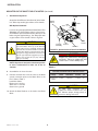
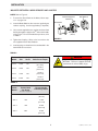
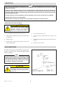
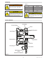
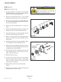
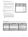
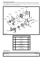
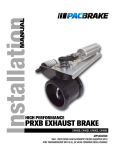
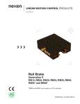
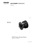
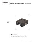
ECLIPSE PRODUCTS
TM
User Manual
Eclipse Servo Motor Brake
Flange Mounted, Pneumatically Engaged, Spring Released
Sizes 2, 3, 4, and 5
1
FORM NO. L-21067-C-0813
In accordance with Nexen’s established policy of constant product improvement, the specifications contained in this
manual are subject to change without notice. Technical data listed in this manual are based on the latest information
available at the time of printing and are also subject to change without notice.
Technical Support: 800-843-7445
(651) 484-5900
www.nexengroup.com
DANGER
Read this manual carefully before installation and operation.
Follow Nexen’s instructions and integrate this unit into your
system with care. This unit should be installed, operated and
maintained by qualified personnel ONLY. Improper installation
can damage your system, cause injury or death. Comply with
all applicable codes.
This document is the original, non-translated, version.
Conformity Declaration: In accordance with Appendix II B of CE Machinery Directive (2006/42/EC):
A Declaration of Incorporation of Partly Completed Machinery evaluation for the applicable EU directives was
carried out for this product in accordance with the Machinery Directive. The declaration of incorporation is set
out in writing in a separate document and can be requested if required.
This machinery is incomplete and must not be put into service until the machinery into which it is to be
incorporated has been declared in conformity with the applicable provisions of the Directive.
Nexen Group, Inc.
560 Oak Grove Parkway
Vadnais Heights, Minnesota 55127
ISO 9001 Certified
Copyright 2013 Nexen Group, Inc.
FORM NO. L-21067-C-0813
2
Table of Contents
General Specifications ---------------------------------------------------------------------------------------------------------------------- 4
General Safety Precautions --------------------------------------------------------------------------------------------------------------- 4
Installation:
Mounted on the Shaft End of a Motor ------------------------------------------------------------------------------- 5
Mounted between a Gear Reducer and a Motor ------------------------------------------------------------------------ 7
Lubrication ---------------------------------------------------------------------------------------------------------------------------------------- 8
Air Connections-----------------------------------------------------------------------------------------------------------------------------------8
Operation ------------------------------------------------------------------------------------------------------------------------------------------ 9
Brake Assembly ----------------------------------------------------------------------------------------------------------------------------------9
Troubleshooting---------------------------------------------------------------------------------------------------------------------------------11
Replacement Parts List-----------------------------------------------------------------------------------------------------------------------12
Accessories---------------------------------------------------------------------------------------------------------------------------------------12
Warranty-------------------------------------------------------------------------------------------------------------------------------------------13
3
FORM NO. L-21067-C-0813
GENERAL SPECIFICATIONS
Min Holding
Torque
Torsional Rigidity
(Estimated)
Inertia
(Calculated)
Weight
Min. Disengagement
Air Pressure
Size 2
1.9 Nm
[17 in-lb]
4431 Nm/RAD
[3267 ft*lb/RAD]
0.00002 kg*m^2
[0.0005 lb*ft^2]
56 watts
[0.075 HPT]
1.1 kg
[2.5 lbs]
Size 3
11.3 Nm
[100 in-lb]
5287 Nm/RAD
[3900 ft*lb/RAD]
0.00007 kg*m^2
[0.0016 lb*ft^2]
104 watts
[0.14 HPT]
2 kg
[4.5 lbs]
Size 4
22.6 Nm
[200 in-lb]
7456 Nm/RAD
[5500 ft*lb/RAD]
0.00024 kg*m^2
[0.0058 lb*ft^2]
135 watts
[0.18 HPT]
4.5 kg
[9.9 lbs]
Size 5
45.2 Nm
[400 in-lb]
23448 Nm/RAD
[17294 ft*lb/RAD]
0.00117 kg*m^2
[0.0276 lb*ft^2]
149 watts
[0.20 HPT]
7.5 kg
[16.6 lbs]
Size
Pneumatic units accept an optional solenoid valve (normally closed) controlled by 24VDC at 104 mA. Solenoid valves are
fitted with 18” flying leads standard. To order the solenoid valve (optional), please refer to Nexen product #964650.
GENERAL SAFETY PRECAUTIONS
CAUTION
WARNING
Watch for sharp features when
interacting with this product. The parts
have complex shapes and machined
edges.
This product is capable of emitting
a spark if misused, therefore it is not
recommended for use in any explosive
environment.
WARNING
The output shaft needs to be enclosed
either by gear reducer or appropriate
guarding. Failure to guard could result
in serious bodily injury.
CAUTION
WARNING
The temperature limits for the product
are 4.5-100 degree Celsius (40-220
degree F).
FORM NO. L-21067-C-0813
The output shaft needs to be enclosed
either by gear reducer or appropriate
guarding. Failure to guard could result
in serious bodily injury.
4
INSTALLATION
INSTALLATION ONTO MOTOR SHAFT
NOTE: Refer to Figures 1, 2 & 3.
Prior to performing any installation steps, Nexen
recommends applying air pressure to the Servo Brake.
When air pressure is applied, the brake will remain
engaged, and the shaft will not rotate. This will aid in the
following installation operations.
Clamping Collar
(Item 7)
1. Place the Clamping Collar (Item 7) on the input
(female) end of the servo brake shaft. Finger tighten
the cap screw until the Collar is nearly snug. Then slide
the Collar down the Shaft until it is firmly against the
shaft step.
FIGURE 1
NOTE: The Clamp Collar for size 4 and 5 requires two cap
screws to provide necessary clamp load.
Access Plug
(Item 14)
2. Remove the Access Plugs (Item 14) from the Input
Flange (Item 10). Rotate the Clamping Collar (Item
7) until the cap screw is lined up with the access
hole. Then insert an Allen driver or a T-handle wrench
through and engage the head of the cap screw. Leave
this driver or wrench in place while you perform the
next two steps.
Input Flange
(Item 10)
CAUTION: Do not lubricate either the Clamping
Collar or the Shaft. Any lubricant on the contact
surfaces could result in torque transfer failure. If
necessary, clean the Shaft with a non-petroleum
based solvent, such as isopropyl alcohol, and wipe
dry before assembly.
FIGURE 2
3. Slide the Motor Shaft into the input (female) end of the
Output Shaft (Item 1) until the Flanges of the Motor
and Brake come together.
Servo Motor
4. Using four customer-supplied Socket Head Cap
Screws (See Table 3), bolt the Flanges together.
Tighten the cap screws evenly to the recommended
torques listed in Table 3 (Page 7).
5. Using the Allen driver or wrench used in Step 2,
tighten the cap screws in the Clamping Collar (Item
7) to the recommended torque listed in Table 2 (Page
7).
Output Shaft
(Item 1)
FIGURE 3
CAUTION: Under-tightening the Collar may cause
slippage between the motor and the Brake. This
can cause damage to the System, Motor and/or
Brake.
DANGER
Support the load before disengaging
the brake. Failure to support the load
could result in serious bodily injury.
6. Reinstall the Access Plugs (Item 14) into the access
holes on the Input Flange (Item 10).
5
FORM NO. L-21067-C-0813
INSTALLATION
MOUNTED ON THE SHAFT END OF A MOTOR (continued)
7. Standard Configuration:
To Brake
Attach the Quick Exhaust Valve (Item 23) to the brake.
Use Teflon tape and/or pipe sealant on the threads.
With Optional Solenoid:
If you are using the optional Solenoid Valve (Nexen Part
#964650), the Quick Exhaust Valve is unnecessary.
Assemble the optional Solenoid Valve directly to the
brake using the supplied fittings. Use Teflon tape and/
or pipe sealant on the threads. Refer to Figure 4.
Exhaust
Silencer
1/8 NPT
CAUTION
Air Supply
Tube Fitting
The Servo Brake will engage if you depress
the domed button at the top of the Solenoid
Valve (if air pressure is supplied). The LED will
illuminate when the Solenoid Valve is actuated
and the Servo Brake is engaged. Unit has been
designed to engage before (at or below) 5.5
bar [80 psi]. Required engagement pressure
higher than 5.5 bar [80 psi] may indicate
improper assembly.
Lead Wires
FIGURE 4 Optional Solenoid Valve Part #964650.
DANGER
Support the load before disengaging
the brake. Failure to support the load
could result in serious bodily injury.
NOTE: Align the air inlet ports in the down position
to allow condensation to drain out of the air
chamber.
TABLE 1
8. Assemble the air line to the valve.
OPTIONAL SOLENOID VALVE SPECIFICATIONS
9. Connect the lead wires from the valve to the brake
control connection points on the Motor Drive or the
PLC. Refer to Table 1.
Lead Wire Cable:
Brown wire = positive
White wire = common
Green wire = ground
Voltage
Power
Resistance
Current
CV
Standard Coil:
24VDC
4 Watts
145 Ohms
.17 Amps
.25
CAUTION
24 VDC valve connector has a
suppression diode installed across the
coil. Observe proper voltage polarity or
connector damage will result.
10.Attach the Gear Reducer or the load to the Brake
Shaft.
FORM NO. L-21067-C-0813
Manual
Override
DIN
Connector
6
INSTALLATION
MOUNTED BETWEEN A GEAR REDUCER AND A MOTOR
NOTE: Refer to Figure 5.
Customer Supplied
Fastener
1. To mount the Servo Brake to the Motor, follow steps
1-11 on pages 5-6.
Gear Reducer
Servo Motor
2. Insert the Brake Shaft into the customer supplied gear
reducer coupling. Use the supplied key (if required).
3. Use customer supplied screws, washers and nuts to bolt
the flanges together. Apply Loctite® 242 to the threads
of the screws. For recommended torque values, refer
to Table 3.
Clamp Collar
(Item 7)
FIGURE 5
4. Tighten the Coupling. Refer to the instructions that
are supplied with the Gear Reducer.
5. Install any plugs or related items that are detailed in the
Gear Reducer instructions.
TABLE 2
Brake
Model
Shaft
Size
Cap
Screw
Recommended
Collar Screw Torque
Size 2
14 mm
M5
9.5 N-m
[84.1 in-lb]
Size 3
16 mm
M6
16.0 N-m
[142.0 in-lb]
Size 4
15 mm
M6
16.0 N-m
[142.0 in-lb]
Size 5
24 mm
M6
16.0 N-m
[142.0 in-lb]
DANGER
Support the load before disengaging
the brake. Failure to support the load
could result in serious bodily injury.
TABLE 3
Socket Head
Cap Screw
Recommended
Fastening Torque
Size 2
M5
7 Nm
[63 in-lb]
Size 3
M6
12 Nm
[107 in-lb]
Size 4
M8
29 Nm
[260 in-lb]
Size 5
M10
58 Nm
[520 in-lb]
Brake
Model
(Customer Supplied)
7
FORM NO. L-21067-C-0813
LUBRICATION
NOTE
Note: Nexen pneumatically actuated devices require clean, pressure regulated air for maximum performance
and life. Nexen pneumatically operated devices pneumatic seals are lubricated life, and do not require
additional lubrication.
However, some customers prefer to use an air line lubricator, which injects oil into the pressurized air,
forcing an oil mist into the air chamber. This is acceptable, but care must be taken to ensure once an air mist
lubrication system is used, it is continually used over the life of the product as the oil mist may wash free the
factory installed lubrication.
Locate the lubricator above and within ten feet of the product, and use low viscosity oil such as SAE-10.
Synthetic lubricants are not recommended.
Nexen product's bearings are shielded and pre-lubricated, and require no further lubrication.
LUBRICATOR DRIP RATE SETTINGS
CAUTION
These settings are for Nexen supplied
lubricators. If you are not using a Nexen
lubricator, calibration must follow the
manufacturer’s suggested procedure.
1. Close and disconnect the air line from the unit.
5. Connect the air line to the unit.
2. Turn the Lubricator Adjustment Knob counterclockwise three
complete turns.
6. Turn the Lubricator Adjustment Knob clockwise until
closed.
3. Open the air line.
7.
4. Close the air line to the unit when a drop of oil forms in the
Lubricator Sight Gage.
8. Open the air line to the unit.
AIR CONNECTIONS
All Nexen pneumatically actuated devices require clean
and dry air, which meet or exceeds ISO 8573.1:2001
Class 4.4.3 quality.
NOTE
For quick response, Nexen recommends a quick
exhaust valve and short air lines between the
Control Valves and the unit. Align the air inlet ports
to a down position to allow condensation to drain
out of the air chambers of the product.
CAUTION
Low air pressure will cause slippage and
overheating. Excessive air pressure will
cause abrupt starts and stops, reducing
product life.
FORM NO. L-21067-C-0813
8
Turn the Lubricator Adjustment Knob counterclockwise onethird turn.
OPERATION
TABLE 4
WARNING
Never exceed maximum operating speeds
listed for your product. (See Table 4).
Sizes
Max RPM
Size 2
9,000
Size 3
8,000
Size 4
5,000
Size 5
4,500
CAUTION
Never exceed life of facing material. Facing
life depends on the volume of material and
the total energy over the life of the unit.
Expected life (in hrs) can be found by:
Time=Volume/(Power*Wear Rate).
CAUTION
The temperature limits for this product
line are 4.5-100 Degree Celsius (40220 Degree F).
BRAKE ASSEMBLY
Friction Facing
Air Chamber
Piston
O-Ring Seals
Input Flange
Clamping Collar
Output Shaft
Bearing
Coil Spring
Air to Brake
Quick Exhaust Valve
and/or
Optional Soleniod Valve
FIGURE 6
9
FORM NO. L-21067-C-0813
BRAKE ASSEMBLY
SIZES 2, 3, 4, 5
CAUTION
Working with spring or tension loaded
fasteners and devices can cause injury.
Wear safety glasses and take the
appropriate safety precautions.
NOTE: Refer to Figures 7 & 8.
1. Alternately and evenly, remove the four Socket Head
Cap Screws (Item 11) and separate the Air Chamber
(Item 6) from the Input Flange (Item 10).
2. Remove the Output Shaft (Item 1) from the Ball
Bearing (Item 2) by pressing in on the output shaft.
Item 20
3. Remove the Piston (Item 5) from the Air Chamber (Item
6). You may need to apply compressed air to the air
inlet to remove the Piston.
Item 4
Item 5
Item 3
4. Remove the old O-ring Seals (Items 3, 4) from the
Piston.
Item 8
Item 6
Item 1
Item 2
5. Remove the Retaining Ring (Item 21) and press the
Bearing (Item 2) out of the Air Chamber (Item 6).
Item 21
6. Clean the bearing bore of the Air Chamber (Item 6)
with fresh solvent, removing old Loctite®.
Item 23
FIGURE 7
7. Apply a continuous bead of Loctite® 680 around
the inner circumference of the Air Chamber (Item 6)
bearing bore.
8. Carefully align the outer race of the new Bearing (Item
2) with the bore of the Air Chamber (Item 6).
Item 14
9. Supporting the Air Chamber (Item 6) and pressing on
the outer race of the new Bearing (Item 2), press the
new Bearing into the Air Chamber.
Fused End
*Size 2 Only
Item 11
10.Visually inspect the inner diameter grooves and the
outer diameter grooves of the Piston (Item 5) for
debris. Clean as necessary.
Item 10
Item 9
11. Reinstall the retaining ring.
Item 7
12. Coat the O-ring contact surfaces of the Air Chamber
(Item 6), the Piston (Item 5), and the O-ring Seals
(Items 3, 4) with a thin film of O-ring lubricant and
install the new O-ring Seals.
FIGURE 8
13. Slide the Piston (Item 5) into the Air Chamber
(Item 6).
14.Clean the friction surface of the Input Flange and
Output Shaft (Item 6) with solvent.
(continued...)
FORM NO. L-21067-C-0813
10
BRAKE ASSEMBLY (continued...)
15. Position the Friction Facing on top of the piston with
the narrow end of the taper pointing up. Use care to
ensure that the Friction Facing is concentric to the
piston, as this will aid in the installation of the output
shaft in step 16.
TABLE 5
16. Support the inner race of the new Ball Bearing (Item
2) and press the Output Shaft (Item 1) into the new
Bearing (Item 2) and Air Chamber (Item 6).
17. Replace the Spring (Item 9) and Input Flange (Item
10).
NOTE: On the Size 2 Spring, one end will be fused. Be
sure that the fused end is down and makes contact with
the facing (Item 8).
Brake
Model
Socket Head
Cap Screw
Recommended
Assembly
Torque
Size 2
M4
4.2-5.4 Nm
[37-48 in-lb]
Size 3
M5
7.0-9.2 Nm
[62-81 in-lb]
Size 4
M6
9.2-11.9 Nm
[81-105 in-lb]
Size 5
M8
26.2-34.0 Nm
[232-301 in-lb]
(Item 11)
18.Apply a drop of Loctite® 242 to the threads of the
Socket Head Cap Screws (Item 11).
19.Reinstall and tighten the four Socket Head Cap
Screws (Item 11), securing the Air Chamber (Item 6)
to the Input Flange (Item 10). Alternate as you tighten
the four Socket Head Cap Screws so that the Input
Flange remains evenly parallel to the Air Chamber.
Refer to Table 5 for the recommended assembly torque
values.
TROUBLESHOOTING
Problem
Probable Cause
Solution
Failure to disengage (brake).
Weak or broken spring.
Replace broken spring.
Failure to engage (1).
Control valve malfunction - air not getting to the
brake.
Check for low air pressure or replace
the control valve.
NOTE: Pressure needed to engage
should NOT exceed 80 psi.
Failure to engage (2).
Air is leaking around the O-ring seals.
Replace the O-rings.
Loss of torque.
Friction Facing is worn or dirty.
Replace the Friction Facing.
11
FORM NO. L-21067-C-0813
REPLACEMENT PARTS LIST
To order replacement parts, indicate servo brake model size, item number, item description, and quantity. Replacement
parts are available through your local Nexen Distributor.
Item 8
Item 4
Item 5
Item 3
Item 6
Item 2
Item 14
Item 21
Item 11
Fused End
*Size 2 Only
Item 23
Item 10
Item 9
Item 7
Item 20
Item 1
FIGURE 9
ITEM
DESCRIPTION
QTY
1
2
3
4
5
6
7
8
9
10
11
12
14
20
21
23
Output Shaft
Ball Bearing
O-ring Seal
O-ring Seal
Piston
Air Chamber
Clamping Collar
Friction Facing
Spring
Input Flange
Socket Head Cap Screw
Solenoid Valve (Optional)
Access Plug
Key
Retaining Ring
Quick Exhaust Valve, Eclipse
1
1
1
1
1
1
1
1
1
1
4
1
1
1
1
1
ACCESSORIES
DESCRIPTION
PROD. NO.
Optional Solenoid Valve........................................................................................................................................................................................................964650
FORM NO. L-21067-C-0813
12
WARRANTY
Warranties
Nexen warrants that the Products will (a) be free from any defects in material or workmanship for a period of 12 months
from the date of shipment, and (b) will meet and perform in accordance with the specifications in any engineering drawing
specifically for the Product that is in Nexen’s current product catalogue, or that is accessible at the Nexen website, or that is
attached to this Quotation and that specifically refers to this Quotation by its number, subject in all cases to any limitations
and exclusions set out in the drawing. NEXEN MAKES NO OTHER WARRANTY, EXPRESS OR IMPLIED, AND ALL
IMPLIED WARRANTIES, INCLUDING WITHOUT LIMITATION, IMPLIED WARRANTIES OF MERCHANTABILITY AND
FITNESS FOR A PARTICULAR PURPOSE ARE HEREBY DISCLAIMED. This warranty applies only if: (a) the Product
has been installed, used and maintained in accordance with any applicable Nexen installation or maintenance manual
for the Product; (b) the alleged defect is not attributable to normal wear and tear; (c) the Product has not been altered,
misused or used for purposes other than those for which it was intended; and (d) Buyer has given written notice of the
alleged defect to Nexen, and delivered the allegedly defective Product to Nexen, within one year of the date of shipment.
Exclusive Remedy
The exclusive remedy for the Buyer for any breach of any warranties provided in connection with this agreement will be,
at the election of Nexen: (a) repair or replacement with new, serviceably used, or reconditioned parts or products; or (b)
issuance of credit in the amount of the purchase price paid to Nexen by the Buyer for the Products.
Agent's Authority
Buyer agrees that no agent, employee or representative of Nexen has authority to bind Nexen to any affirmation,
representation, or warranty concerning the Products other than those warranties expressly set forth herein.
Limitation on Nexen’s Liability
TO THE EXTENT PERMITTED BY LAW NEXEN SHALL HAVE NO LIABILITY TO BUYER OR ANY OTHER PERSON
FOR INCIDENTAL DAMAGES, SPECIAL DAMAGES, CONSEQUENTIAL DAMAGES OR OTHER DAMAGES OF
ANY KIND OR NATURE WHATSOEVER, WHETHER ARISING OUT OF BREACH OF WARRANTY OR OTHER
BREACH OF CONTRACT, NEGLIGENCE OR OTHER TORT, OR OTHERWISE, EVEN IF NEXEN SHALL HAVE
BEEN ADVISED OF THE POSSIBILITY OR LIKELIHOOD OF SUCH POTENTIAL LOSS OR DAMAGE. For all of
the purposes hereof, the term "consequential damages" shall include lost profits, penalties, delay damages, liquidated
damages or other damages and liabilities which Buyer shall be obligated to pay or which Buyer may incur based upon,
related to or arising out of its contracts with its customers or other third parties. In no event shall Nexen be liable for any
amount of damages in excess of amounts paid by Buyer for Products or services as to which a breach of contract has
been determined to exist. The parties expressly agree that the price for the Products and the services was determined
in consideration of the limitation on damages set forth herein and such limitation has been specifically bargained for and
constitutes an agreed allocation of risk which shall survive the determination of any court of competent jurisdiction that
any remedy herein fails of its essential purpose.
Inspection
Buyer shall inspect all shipments of Products upon arrival and shall notify Nexen in writing, of any shortages or other failures
to conform to these terms and conditions which are reasonably discoverable upon arrival without opening any carton
or box in which the Products are contained. Such notice shall be sent within 14 days following arrival. All notifications
shall be accompanied by packing slips, inspection reports and other documents necessary to support Buyer's claims. In
addition to the foregoing obligations, in the event that Buyer receives Products that Buyer did not order, Buyer shall return
the erroneously shipped Products to Nexen within thirty (30) days of the date of the invoice for such Products; Nexen
will pay reasonable freight charges for the timely return of the erroneously shipped Products, and issue a credit to Buyer
for the returned Products at the price Buyer paid for them, including any shipping expenses that Nexen charged Buyer.
All shortages, overages and nonconformities not reported to Nexen as required by this section will be deemed waived.
Limitation on Actions
No action, regardless of form, arising out of any transaction to which these terms and conditions are applicable may be
brought by the Buyer more than one year after the cause of action has accrued.
Nexen Group, Inc.
560 Oak Grove Parkway
Vadnais Heights, MN 55127
800.843.7445
Fax: 651.286.1099
www.nexengroup.com
ISO 9001 Certified