1
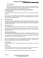
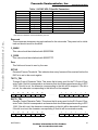
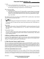
Freescale Semiconductor, Inc.
MOTOROLA
SEMICONDUCTOR
Freescale Semiconductor, Inc...
TECHNICAL INFORMATION
Asynchronous HDLC
MC68360 ASYNC HDLC Protocol Microcode
User’s Manual
Rev 1.1
January 24, 1996
For More Information On This Product,
Go to: www.freescale.com
Freescale Semiconductor, Inc.
Asynchronous HDLC
Asynchronous HDLC
Freescale Semiconductor, Inc...
1
ASYNC HDLC Controller Overview
4
2
ASYNC HDLC Controller Key Features
2.1
ASYNC HDLC Channel Frame Transmission Processing
2.2
ASYNC HDLC Channel Frame Reception Processing
2.3
Transmitter Transparency Encoding
2.4
Receiver Transparency Decoding
2.4.1
Receive Flowchart
2.4.2
Cases not covered by RFC 1549
2.5
Implementation Specifics related to Asynchronous HDLC
2.5.1
FLAG sequence
2.5.2
Address Field
2.5.3
Control Field
2.5.4
Frame Check Sequence
2.5.5
Encoding
2.5.6
Time-Fill
4
4
5
5
6
7
7
8
8
8
8
8
8
8
3
Microcode Use
3.1
Initialization Procedure
3.2
Performance
9
9
9
4
ASYNC HDLC Memory Map
4.1
ASYNC HDLC-Specific Parameters
4.2
Configuring the General SCC Parameters
4.2.1
GSMR Register
4.2.2
DSR Register
9
9
11
11
11
5
ASYNC HDLC Programming Model
5.1
ASYNC HDLC Command Set
5.1.1
Transmit Commands
5.1.2
Receive Commands
5.2
ASYNC HDLC Error Handling Procedure
5.2.1
Transmission Errors
5.2.2
Reception Errors
11
12
12
13
13
13
13
6
Registers
6.1
ASYNC HDLC Event Register
6.2
ASYNC HDLC Mode Register (PSMR)
14
14
15
7
ASYNC-HDLC Rx Buffer Descriptor
16
8
ASYNC-HDLC Tx Buffer Descriptor
18
For More Information On This Product,
Go to: www.freescale.com
2
Freescale Semiconductor, Inc...
Freescale Semiconductor, Inc.
Asynchronous HDLC
9
Differences Between HDLC and ASYNC-HDLC
9.1
Max Received Frame Length Counter
9.2
Frame termination due to error
9.3
Commands
9.4
Automatic Error Counters
9.5
Noisy Characters
19
19
19
20
20
20
Appendix A - Microcode Initialization Procedure
A.1
Initialization Procedure for QUICC Version $0001
A.2
Initialization Procedure for QUICC Revision $0002
A.3
Initialization Procedure for QUICC Version $0003
21
21
21
22
Appendix B - Programming Example
23
Appendix C - References
24
For More Information On This Product,
Go to: www.freescale.com
3
Freescale Semiconductor, Inc.
Asynchronous HDLC
1 ASYNC HDLC Controller Overview
Asynchronous HDLC is a frame-based protocol which uses HDLC framing techniques in
conjunction with UART-type characters. This protocol is typically used as the physical layer
for the Point-to-Point (PPP) protocol. While this protocol can be implemented by the UART
controller on the QUICC in conjunction with the CPU32+, it is more efficient and less compute-intensive for the CPU to allow the Communications Processor Module (CPM) of the
QUICC to perform the framing and transparency functions of the protocol.
2 ASYNC HDLC Controller Key Features
• Flexible data buffer structure which allows an entire frame or a section of a frame to be
transmitted and received.
Freescale Semiconductor, Inc...
• Separate interrupts for received frames and transmitted buffers
• Automatic CRC generation and checking (CRC-CCITT)
• Support for NMSI control signals (Carrier Detect, Clear to Send, Ready to Send)
• Automatic generation of opening and closing flags
• Reception of frames with only one “shared” flag
• Automatic generation and stripping of transparency characters according to RFC 1549
utilizing transmit and receive control character maps.
• Automatic transmission of the ABORT sequence (0x7D,0x7E) after the STOP TRANSMIT command is issued.
• Automatic transmission of IDLE characters between frames and characters.
• “Small” RAM Microcode (consumes 768 bytes of Dual-Port RAM)
2.1 ASYNC HDLC Channel Frame Transmission Processing
The ASYNC HDLC Controller is designed to work with a minimum amount of intervention
from the CPU32+ core. It operates in a similar fashion to the HDLC controller on the QUICC.
When the core enables one of the transmitters and sets the ready (R) bit in the first Buffer
Descriptor, the ASYNC HDLC Controller fetches the data from memory and start transmitting the frame (after transmitting the opening flag). When the controller reaches the end of
the current BD, the CRC and the closing flag are appended if the last (L) bit in the Tx BD is
set. If the continuous mode (CM) bit is clear, the ASYNC HDLC transmitter writes the frame
status bits into the BD and clears the ready bit. If the interrupt (I) bit is set, the controller sets
the TXB event bit in the event register. Thus, the I bit may be used to generate an interrupt
after each buffer, after a group of buffers, or after each complete frame has been transmitted.
If the CM bit in the Tx BD is set, the ASYNC HDLC controller will write the signal unit status
bits into the BD after transmission but it will not clear the ready bit.
The ASYNC HDLC controller will then proceed to the next Tx BD in the table. If it is not
ready, the ASYNC HDLC controller will wait until the Tx BD is ready.
MOTOROLA
For More Information On This Product,
Go to: www.freescale.com
4
Freescale Semiconductor, Inc.
Asynchronous HDLC
While the ASYNC HDLC controller is transmitting data from the buffers, it automatically performs the transparency encoding specified by the protocol. This encoding is described in detail in section 2.3 on page 5.
If the user wishes to re-arrange the transmit queue before the Communications Processor
(CP) has completed transmission of all buffers, the user should issue the STOP TRANSMIT
command. This can be useful for transmitting expidited data prior to previously linked buffers
or for error situations. The ASYNC HDLC controller, when receiving the STOP TRANSMIT
command, will stop transmitting and will send the ASYNC HDLC ABORT sequence (0x7d,
0x7e). It will then transmit IDLE characters until the RESTART TRANSMIT command is given, at which point it will resume transmission with the next Tx BD.
Freescale Semiconductor, Inc...
2.2 ASYNC HDLC Channel Frame Reception Processing
The ASYNC HDLC receiver is also designed to work with a minimum amount of intervention
from the CPU32+ core. The ASYNC HDLC receiver can perform the decoding of the transparency characters, check the CRC of the frame, and detect errors on the line and in the
controller.
When the core enables one of the receivers, the receiver waits for data to be present on the
line. When the receiver detects a data byte of the incoming frame, the ASYNC HDLC controller fetches the next buffer descriptor (BD) and, if the empty (E) bit is set, starts transferring the incoming frame into the BD's associated data buffer. When the data buffer is full,
the ASYNC HDLC controller clears the empty bit in the BD. If the incoming frame exceeds
the length of the data buffer (as defined in the MRBLR parameter), the ASYNC HDLC controller fetches the next BD in the table and, if empty, continues to transfer the rest of the
frame into this BD's associated data buffer.
During this process, the receiver will automatically perform the transparency character decoding required of the ASYNC HDLC protocol. This procedure is described in detail in section section 2.4 on page 6.
When the frame ends, the controller checks the incoming CRC field and writes it to the data
buffer. It then writes the length of the entire frame to the data length field of the last BD. The
ASYNC HDLC controller sets the last (L) bit, writes the frame status bits into the BD, and
clears the empty bit if the continuous mode (CM) bit is clear. It then sets the RXF bit in the
event register indicating that a frame has been received and is in memory. The ASYNC
HDLC controller then waits for the start of the next frame which may, or may not, have an
opening FLAG.
2.3 Transmitter Transparency Encoding
The ASYNC-HDLC Controller mapps characters according to RFC 1549. It will examine the
outgoing data bytes and perform the transparency algorithm on a given byte if it matches
one of the following criteria:
• The byte is a FLAG (0x7E)
• The byte is a Control-Escape Character (0x7D)
MOTOROLA
For More Information On This Product,
Go to: www.freescale.com
5
Freescale Semiconductor, Inc.
Asynchronous HDLC
• The byte has a value between 0x00 and 0x1F and the corresponding bit in the TX Control Character Table is set.
If the outgoing byte matches one of these three criteria, a two-byte sequence is transmitted
in place of the byte. This sequence consists of the Control-Escape Character (0x7D) followed by the original byte exclusive-or’ed with 0x20.
For more information on the transparency algorithm, please see the references in Appendix
C - References.
2.4 Receiver Transparency Decoding
Freescale Semiconductor, Inc...
The ASYNC-HDLC Controller maps characters according to RFC 1549. It will examine the
incoming data bytes and perform the transparency algorithm to recover the original data.
The algorithm does the following:
• Discards any character that has its corresponding bit set in the RX Control Character
Map. This character is assumed to have been inserted in the character stream by an
intermediate device and thus not be part of the originally transmitted frame.
• Reverses the transmission transparency sequence by discarding a received ControlEscape Character (0x7D) and exclusive-or’ing the following byte with 0x20 before performing the CRC calculation and writing the byte into memory.
For more information on the transparency algorithm, please see the references in Appendix
C - References.
The receive Flow-chart is shown below to detail the algorithm because there are some cases which are not addressed in the RFC.
MOTOROLA
For More Information On This Product,
Go to: www.freescale.com
6
Freescale Semiconductor, Inc.
Asynchronous HDLC
2.4.1 Receive Flowchart
begin
char<$20
F
Freescale Semiconductor, Inc...
Check Rx ACCM
xornext?
T
mapped?
T
discard
char
F
char=$7D
xornext:=1
F
discard
char
char=$7e?
T
F
char=$7e?
Closing
Flag
char:=char xor $20
xornext:=0
Abort
frame
F
perform crc
receive
char
2.4.2 Cases not covered by RFC 1549
The following cases are not covered by RFC 1549.
• If an 0x7D is followed by a control character, and the control character is NOT mapped,
the control character itself will be “modified” by the xor process. It is assumed that this
will be caught by the CRC check.
• In addition to the Abort sequence, frames will be terminated by following errors:
—Noisy Character received
MOTOROLA
For More Information On This Product,
Go to: www.freescale.com
7
Freescale Semiconductor, Inc.
Asynchronous HDLC
—Carrier Detect Lost
—Receiver Overrun
• If the invalid sequence (0x7D, 0x7D) is received, the first control escape character will
be discarded and the second will be unconditionally exclusive-or’ed with 0x20. This sequence will thus be stored in the buffer descriptor as (0x5D).
2.5 Implementation Specifics related to Asynchronous HDLC
Freescale Semiconductor, Inc...
2.5.1 FLAG sequence
When transmitting, the controller automatically generates the opening and closing flag for
the frame.
When receiving, the controller strips off the opening and closing FLAG before writing the
frame to memory. It will receive frames with only one “shared” flag between them. It will also
ignore multiple flags between frames.
2.5.2 Address Field
The address field is neither generated nor examined by the microcode while transmitting or
receiving. The address field of the frame must be included in the data buffer pointed to by
the transmit buffer descriptor. Any address field compression, expansion, or checking must
be performed by the core.
2.5.3 Control Field
The control field is neither generated nor examined by the microcode while transmitting or
receiving. The control field of the frame must be included in the data buffer pointed to by the
transmit buffer descriptor. Any control field compression, expansion, or checking must be
performed by the core.
2.5.4 Frame Check Sequence
When transmitting, the frame check sequence (CRC) is automatically appended to the end
of the frame prior to transmission of closing flag. The frame check sequence is generated
on the original frame before addition of transparency characters, start/stop bits, or flags. The
controller will only use a 16-bit CRC-CCITT polynomial.
When receiving, the frame check sequence is automatically checked. The frame check sequence is calculated after removal of any transparency chaaracters, start/stop bits, and
flags. The controller will only use a 16-bit CRC-CCITT polynomial.
2.5.5 Encoding
The Asynchronous-HDLC controller only supports 8 data bits, one start bit, one stop bit, and
no parity.
2.5.6 Time-Fill
When transmitting, the Asynchronous HDLC controller will transmit IDLE characters (characters consisting of only “1”s) when no data is available for transmission.
When receiving, the Asynchronous HDLC controller will ignore any IDLE characters.
MOTOROLA
For More Information On This Product,
Go to: www.freescale.com
8
Freescale Semiconductor, Inc.
Asynchronous HDLC
3 Microcode Use
The Asynchronous HDLC microcode must be loaded into QUICC DPRAM at initialization
time. It is a ‘small’ (512 byte) microcode and thus will consume the memory area from DPRBASE + $000 to DPRBASE + $1FF. In addition, the “Microcode Scratch” area of the memory
map from DPRBASE + $600 to DPRBASE + $6FF will be inaccessible to the user. (See Section 3.1 of the MC68360 User’s Manual for more information.)
The memory areas listed above are physically locked once the ERAM bit is set in the RCCR
register. Thus, any reads or writes to that area by the CPU32+ will have no effect on memory
or the microcode.
Freescale Semiconductor, Inc...
3.1 Initialization Procedure
See Appendix A - Microcode Initialization Procedure, for instructions on how to load and initialize the microcode.
3.2 Performance
At 25Mhz, an aggregate Asynchronous HDLC data rate of 3 Mbps divided among the 4
SCCs consumes 100% of the processing power of the RISC communications engine. If only
a percentage of the total available Asynchronous HDLC data rate is used, the remaining
RISC processing power can be used to run other protocols on other channels.The following
table illustrates some example configurations of the QUICC using the ASYNC-HDLC microcode. This table can be used in conjunction with the table in Appendix A of the MC68360
User’s Manual to determine if your desired configuration can be handled by the QUICC.
AHDLC Channels
1 x 115 Kbit/s
2 x 230 Kbit/s
3 x 230 Kbit/s
Risc Bandwidth
Consumed (est)
4%
15%
24%
Possible Configuration of Other Channels
1 x 10Mbit Ethernet, 2 x 1.5 Mbit HDLC, 9.6 Kbit SMC UART
1 x 10Mbit Ethernet, 1 x 1.5 Mbit HDLC, 9.6 Kbit SMC UART
1 x 5Mbit HDLC, 2 x 9.6 Kbit SMC UART
The “Risc Bandwidth Consumed” column indicates the amount of RISC bandwidth
being consumed by the ASYNC HDLC controller only.
4 ASYNC HDLC Memory Map
4.1 ASYNC HDLC-Specific Parameters
When configured to operate in ASYNC HDLC mode, the QUICC overlays the structure illustrated listed in Table 7-5 with the ASYNC HDLC-specific parameters described in Table 1.
Table 1. ASYNC HDLC-Specific Parameters
Address
SCC Base+34
SCC Base+38
SCC Base+3C
SCC Base+3E
SCC Base+40
SCC Base+42
SCC Base+44
MOTOROLA
Name
C_MASK
C_PRES
Reserved
Reserved
Width
Long
Long
Word
Word
Word
Word
Word
Description
CRC Constant
CRC Preset
For More Information On This Product,
Go to: www.freescale.com
9
Freescale Semiconductor, Inc.
Asynchronous HDLC
Table 1. ASYNC HDLC-Specific Parameters
Address
SCC Base+46
SCC Base+48
SCC Base+4A
SCC Base+4C
SCC Base+4E
SCC Base+50
SCC Base+54
SCC Base+58
SCC Base+5A
Name
Zero
Reserved
RFTHR
Reserved
Reserved
TXCTL_TBL
RXCTL_TBL
Width
Word
Word
Word
Word
Word
Long
Long
Word
Word
Description
Must be initialized to zero by user
Received Frames Threshold
TX Control Character Mapping Table
RX Control Character Mapping Table
Freescale Semiconductor, Inc...
Note: Entries in boldface must be initialized by the user.
Reserved
These areas are temporary storage locations for the microcode. They need not be initialized and should never be modified.
C_MASK
This value should be initialized with $0000F0B8.
C_PRES
This value should be initialized with $0000FFFF.
Zero
This field must be set to zero by the user.
RFTHR
Received Frames Threshold. This indicates how many frames will be received before the
RXF bit is set in the event register.
TXCTL_TBL
Transmit Control Character Table. This stores the bit array used for the TX Control Character Table. Each bit corresponds to a character that should be mapped according to RFC
1549. If the bit is set, the character corresponding to that bit will be mapped. If the bit is
not set, the character corresponding to that bit will not be mapped.
31
0x1F
30
0x1E
29
0x1D
28
0x1C
27
0x1B
26
0x1A
25
0x19
................
5
0x05
4
0x04
3
0x03
2
0x02
1
0x01
0
0x00
RXCTL_TBL
Receive Control Character Table. This stores the bit array used for the RX Control Character Table. Each bit corresponds to a character that should be mapped according to RFC
1549. If the bit is set, the character corresponding to that bit will be discarded if received.
If the bit is not set, the character corresponding to that bit will be received normally.
31
0x1F
30
0x1E
MOTOROLA
29
0x1D
28
0x1C
27
0x1B
26
0x1A
25
0x19
................
5
0x05
4
0x04
For More Information On This Product,
Go to: www.freescale.com
3
0x03
2
0x02
1
0x01
0
0x00
10
Freescale Semiconductor, Inc.
Asynchronous HDLC
4.2 Configuring the General SCC Parameters
The general SCC parameters can be configured as described on pages 7-112 through 7131 of the QUICC User’s Manual except for the following changes:
Freescale Semiconductor, Inc...
4.2.1 GSMR Register
The General SCC Mode Register bits are the same except for:
RFW—Rx FIFO Width
0— Should not be used
1— Low-latency operation. The Rx FIFO is 8-bits wide, and the receive FIFO is one
fourth its normal size (8 bytes for SCC1 and 4 bytes for the other SCCs). This allows data to be writeen to the data buffer each time a character is received, without
waiting for 32 bits to be received. This configuration must be chosen for characteroriented protocols such as UART, BISYNC, and ASYNC-HDLC.
TDCR—Transmit Divide Clock Rate
The TDCR bits determine the divider rate of the transmitter. If the DPLL is not used, the
1x value should be chosen, except in asynchronous UART mode or Asynchronous-HDLC
mode where 8x, 16x, or 32x must be chosen. The user should program TDCR to equal
RDCR in most applications.
00— do not use
01— 8x clock mode
10— 16x clock mode
11— 32x clock mode
RDCR—Receive DPLL Clock Rate
The RDCR bits determine the divider rate of the receive DPLL. If the DPLL is not used,
the 1x value should be chosen, except in asynchronous UART mode or AsynchronousHDLC mode where 8x, 16x, or 32x must be chosen. The user should program RDCR to
equal TDCR in most applications.
00— do not use
01— 8x clock mode
10— 16x clock mode
11— 32x clock mode
4.2.2 DSR Register
The SCC Data Synchronization Register is reserved in Asynchronous-HDLC mode. It
should be set to zero.
5 ASYNC HDLC Programming Model
The core configures each SCC to operate in one of the protocols by setting the MODE bits
in the GSMR. The ASYNC HDLC controller uses the same data structure as in the other protocols. This data structure supports multi-buffer operation.
The receive errors are reported through the Rx BD. The transmit errors are reported through
the Tx BD. An indication about the status lines (CD and CTS) is reported through the port C
MOTOROLA
For More Information On This Product,
Go to: www.freescale.com
11
Freescale Semiconductor, Inc.
Asynchronous HDLC
pins. A maskable interrupt may be generated upon a status change in either one of those
lines.
5.1 ASYNC HDLC Command Set
The following commands are issued to the Command Register (CR) documented in Section
7.1 of the MC68360 User’s Manual.
Freescale Semiconductor, Inc...
5.1.1 Transmit Commands
After a hardware or software reset and the enabling of the channel in the SCC mode register, the channel is in the transmit enable mode and starts polling the first BD in the table every 8 transmit bit-times, or immediately if the TOD bit in the TODR is set.
STOP TRANSMIT Command
The STOP TRANSMIT command transmits the Asynchronous HDLC ABORT sequence
($7d, $7e) and then disables the transmission of data. If this command is received by the
ASYNC HDLC controller during frame transmission, the ABORT sequence will be placed
into the FIFO and the transmitter will not attempt to send any more data from the current Tx
BD. The controller does not advance to the next Tx BD. You can determine which BD was
terminated by examining the TBPTR entry in the SCC parameter RAM table. No new BD will
be accessed for this channel.
Note
Unlike the other QUICC protocols, the Asynchronous HDLC
controller does not flush the FIFO due to the STOP TRANSMIT
command. Thus, up to 16 characters (32 on SCC1) may be
transmitted before the ABORT sequence is transmitted. This
can be avoided by programming TFL to 1 in the GSMR register.
GRACEFUL STOP TRANSMIT Command
This command is not supported by the Asynchronous HDLC controller.
RESTART TRANSMIT Command
The RESTART TRANSMIT command re-enables the transmission of characters on the
transmit channel. This command is expected by the ASYNC HDLC controller after a STOP
TRANSMIT command or after a transmitter error. The ASYNC HDLC controller will resume
transmission from the first character in the current transmitter BD (TBPTR) in the channel’s
transmit BD table.
INIT TX PARAMETERS Command
Initializes all the transmit parameters in this serial channel’s parameter RAM to their reset
state. This command must be issued before the transmitter is enabled for the first time. This
command should only be issued when the transmitter is disabled. Note that the INIT TX
AND RX PARAMETERS command may also be used to reset both transmit and receive parameters.
MOTOROLA
For More Information On This Product,
Go to: www.freescale.com
12
Freescale Semiconductor, Inc.
Asynchronous HDLC
5.1.2 Receive Commands
After a hardware or software reset and the enabling of the channel by its SCC mode register,
the channel is in the receive enable mode and will use the first BD in the table.
ENTER HUNT MODE Command
This command is not supported by the ASYNC HDLC controller.
Freescale Semiconductor, Inc...
CLOSE RX BD Command
This command is not supported by the ASYNC HDLC controller.
INIT RX PARAMETERS Command
This command initializes all the receive parameters in this serial channel’s parameter RAM
to their reset state. This command should only be issued when the receiver is disabled. Note
that the INIT TX AND RX PARAMETERS command may also be used to reset both receive
and transmit parameters.
5.2 ASYNC HDLC Error Handling Procedure
The ASYNC HDLC controller reports frame reception and transmission error conditions using the channel BDs and the ASYNC HDLC event register.
5.2.1 Transmission Errors
CTS Lost During Frame Transmission
When this error occurs, the channel terminates buffer transmission, closes the buffer, sets
the Clear to Send lost (CT) bit in the Tx BD, and sets the TXE bit in the SCC Event Register.
The channel will resume transmission from the next Tx BD after the RESTART TRANSMIT
command is given.
5.2.2 Reception Errors
Overrun Error
The ASYNC HDLC controller maintains an internal 32 byte FIFO in SCC1 and 16 byte FIFO
in the other SCCs for receiving data. A receive overrun occurs when the Communications
Processor (CP) was unable to keep up with the data rate or the SDMA channel was unable
to write the received data to memory. The previous data byte and the frame status are lost.
The the controller closes the buffer with the overrun (OV) bit in the BD set and sets the RXF
bit in the SCC Event Register. The receiver then searches for the next frame.
Note
Unlike the HDLC Controller, the ASYNC HDLC controller will not
search for an opening flag after this error occurs. It will start receiving again as soon as possible. Thus, the next frame received
will probably not be a complete frame.
CD Lost During Frame Reception
When this error occurs, the channel terminates frame reception, closes the buffer, sets the
Carrier Detect lost (CD) bit in the BD, and sets the RXF bit in the event register. This error
MOTOROLA
For More Information On This Product,
Go to: www.freescale.com
13
Freescale Semiconductor, Inc.
Asynchronous HDLC
has the highest priority. The rest of the frame is lost and other errors are not checked in that
frame. The receiver then searches for the next frame once CD is reasserted.
Freescale Semiconductor, Inc...
Abort Sequence
An abort sequence is detected by the ASYNC HDLC controller when the ABORT sequence
is received (0x7d followed by 0x7e). When this error occurs, the channel closes the buffer
(if it was already open) by setting the Rx Abort Sequence (AB) bit in the BD and sets the
RXF bit in the SCC Event Register. The CRC error status condition is not checked on aborted frames. If the ABORT sequence was received and no frame was currently being received, the next BD will be opened and then closed with the AB bit set.
CRC Error
When this error occurs, the channel writes the received CRC (Cyclic Redundancy Check)
to the data buffer, closes the buffer, sets the CR bit in the BD, and sets the RXF bit in the
SCC Event Register. After receiving a signal unit with a CRC error, the receiver prepares to
receive the next frame.
Break Sequence Received
This occurs when the UART receiver detects the first character of a break sequence (one or
more all-zero characters). When this error occurs, the channel closes the buffer (if it was already open) by setting the Rx Break Sequence (BRK) bit in the BD, and sets the RXF bit in
the SCC Event Register. The CRC error status condition is not checked. If the Break sequence was received and no frame was currently being received, the next BD will be opened
and then closed with the BRK bit set.
6 Registers
6.1 ASYNC HDLC Event Register
The SCCE register for an SCC is called the ASYNC HDLC Event Register when the SCC is
operating in Asynchronous HDLC mode. The ASYNC HDLC Event Register is a 16-bit register which is used to report events recognized by the ASYNC HDLC channel and generate
interrupts. Upon recognition of an event, the ASYNC HDLC controller will set the corresponding bit in the ASYNC HDLC event register. Interrupts generated by this register may
be masked by the ASYNC HDLC mask register.
The ASYNC HDLC event register is a memory-mapped register that may be read at any
time. A bit is cleared by writing a one (writing a zero does not affect a bit’s value). More than
one bit may be cleared at a time. All unmasked bits must be cleared before the CP will clear
the internal interrupt request. This register is cleared at reset.
15
14
-
MOTOROLA
13
12
GLr
11
GLt
10
9
-
8
IDL
7
6
-
5
4
TXE
For More Information On This Product,
Go to: www.freescale.com
3
RXF
2
BSY
1
TXB
0
RXB
14
Freescale Semiconductor, Inc.
Asynchronous HDLC
bits 15-13, 10-9, 7-5—Reserved, should be written with zeros.
GLr—Glitch on Rx
A clock glitch was detected by this SCC on the receive clock
GLt—Glitch on Tx
A clock glitch was detected by this SCC on the transmit clock
Freescale Semiconductor, Inc...
IDL—Idle Sequence Status Changed
A change in the status of the serial line was detected. The real-time status of the line may
be read in SCCS.
TXE—Tx Error
An error (CTS lost) occurred on the transmitter channel.
RXF—Rx Frame
A complete frame has been received on the ASYNC HDLC channel. This bit is set no
sooner than two bit times after the receipt of the last bit of the closing flag.
BSY—Busy Condition
A frame was received and discarded due to lack of buffers.
TXB—Transmit Buffer
A buffer that had its I bit set has been transmitted on the ASYNC-HDLC channel. This bit
is set no sooner than when the last bit of the closing flag begins its transmission if the buffer is the last one in the frame. Otherwise, this bit is set after that last byte of the buffer has
been written to the transmit FIFO.
RXB—Rx Buffer
A Buffer has been received over the ASYNC-HDLC channel that had its I bit set but not
the L bit.
6.2 ASYNC HDLC Mode Register (PSMR)
Each ASYNC HDLC mode register is a 16-bit, memory-mapped, read-write register that
controls SCC operation. The term ASYNC HDLC mode register refers to the PSMR of the
SCC when that SCC is configured in ASYNC HDLC mode.
15
FLC
14
0
13
1
12
1
11
0
10
0
9
0
8
0
7
0
6
0
5
0
4
0
3
0
2
0
1
0
0
0
Bits 14,11-0—Reserved, must be set to zero.
Bits 13,12—Reserved, must be set to one.
FLC—Flow Control
0— Normal Operation.
1— Asynchronous flow control. When the CTS pin is negated, the transmitter will stop
transmitting at the end of the current character. (If CTS is negated past the middle
MOTOROLA
For More Information On This Product,
Go to: www.freescale.com
15
Freescale Semiconductor, Inc.
Asynchronous HDLC
of the current character, the next full character may be sent, and then transmission
will be stopped.) When CTS is asserted once more, transmission will continue
where it left off. No CTS lost error will be reported. No characters except idles will
be transmitted while CTS is negated.
7 ASYNC-HDLC Rx Buffer Descriptor
Freescale Semiconductor, Inc...
The ASYNC-HDLC controller uses the Rx BD to report information about the received data
for each buffer. An example of the Rx BD process is shown in Figure 7-52 of the User’s Manual.
The first word of the Rx BD contains control and status bits. Bits 12 to 15 and bit 9 are written
by the user; bits 0-7 and 10-11 are set by the CP following frame reception. Bit 15 is set by
the core when the buffer is available to the ASYNC HDLC controller, and it is cleared by the
ASYNC HDLC controller when the buffer is full. The format of the control and status word is
detailed below.
OFFSET + 0
OFFSET + 2
OFFSET + 4
OFFSET + 6
15
E
14
-
13
W
12
I
11
L
10
F
9
CM
8
7
BRK
DATA LENGTH
6
-
5
-
4
I
3
AB
2
CR
1
OV
0
CD
RX DATA BUFFER POINTER
Note: Entries in boldface must be initialized by the user.
E—Empty
0— The data buffer associated with this BD has been filled with received data, or data
reception has been aborted due to an error condition. The CPU32+ core is free to
examine or write to any fields of this Rx BD. The CP will not use this BD again while
the E-bit remains zero.
1— The data buffer associated with this BD is empty, or reception is currently in
progress. This Rx BD and its associated receive buffer are owned by the CP. Once
the E-bit is set, the CPU32+ core should not write any fields of this Rx BD.
Bits 14, 8, 6-4—Reserved, should be set to zero
W—Wrap (Final BD in Table)
0— This is not the last buffer descriptor in the Rx BD table.
1— This is the last buffer descriptor in the Rx BD table. After this buffer has been used,
the CP will receive incoming data into the first BD in the table (the BD pointed to
by RBASE). The number of Rx BDs in this table is programmable, and is determined only by the W-bit and the overall space constraints of the dual-port RAM.
I—Interrupt
0— The RXB bit in the ASYNC HDLC Event Register will not be set after this buffer has
been used, but RXF operation remains unaffected.
1— The RXB or RXF bit in the ASYNC HDLC Event Register will be set when this buffer has been used by the ASYNC HDLC controller.
MOTOROLA
For More Information On This Product,
Go to: www.freescale.com
16
Freescale Semiconductor, Inc.
Asynchronous HDLC
L—Last in frame
This bit is set by the ASYNC HDLC controller when this buffer is the last in a frame. This
implies the reception of a closing flag or reception of an error, in which case one or more
of the BRK, CD, OV, and AB bits are set. The ASYNC HDLC controller will write the number of frame octets to the data length field.
0— This buffer is not the last in a frame.
1— This buffer is the last in a frame.
Freescale Semiconductor, Inc...
F—First in frame
This bit is set by the ASYNC-HDLC controller when this buffer is the first in a frame.
0— The buffer is not the first in a frame.
1— The buffer is the first in a frame.
CM—Continuous Mode
0— Normal operation.
1— The E-bit is not cleared by the CP after this BD is closed, allowing the associated
data buffer to be overwritten automatically when the CP next accesses this BD.
However, the E-bit will be cleared if an error (other than CRC error) occurs during
reception, regardless of the CM bit.
BRK—Break Character Received
The current frame was closed because a Break Character was received.
AB—Rx Abort Sequence
The ASYNC HDLC Abort Sequence or a framing error was received to terminate this
frame.
CR—Rx CRC Error
This frame contains a CRC error. The received CRC bytes are always written to the receive buffer.
OV—Overrun
A receiver overrun occurred during frame reception.
CD—Carrier Detect Lost
The carrier detect signal was negated during frame reception.
Data Length
Data length is the number of octets written by the CP into this BD’s data buffer. It is written
by the CP once as the BD is closed.
When this BD is the last BD in a frame (L=1), the data length contains the total number of
frame octets (including the 2 bytes for CRC).
Note
If the received frame has a length (plus CRC) which is an exact
multiple of MRBLR, the BD with the “L” bit set will not actually
MOTOROLA
For More Information On This Product,
Go to: www.freescale.com
17
Freescale Semiconductor, Inc.
Asynchronous HDLC
have any characters in it and the “Data Length” field will contain
a value equal to the sum of the “Data Length” fields of the other
buffer descriptors in the frame.
The actual amount of memory allocated for this buffer should be greater than or equal to
the contents of the MRBLR.
Rx Data Buffer Pointer
The receive buffer pointer, which always points to the first location of the associated data
buffer, may reside in either internal or external memory.
Freescale Semiconductor, Inc...
8 ASYNC-HDLC Tx Buffer Descriptor
Data is presented to the ASYNC-HDLC controller for transmission on an SCC channel by
arranging it in buffers referenced by the channel’s TX BD table. The HDLC controller confirms transmission (or indicates error conditions) using the BDs to inform the CPU32+ core
that the buffers have been serviced.
OFFSET + 0
OFFSET + 2
OFFSET + 4
OFFSET + 6
15
R
14
-
13
W
12
I
11
L
10
-
9
CM
8
7
DATA LENGTH
6
-
5
-
4
-
3
-
2
-
1
-
0
CT
TX DATA BUFFER POINTER
Note: Entries in boldface must be initialized by the user
R—Ready
0— The data buffer associated with this BD is not ready for transmission. The user is
free to manipulate this BD or its associated data buffer. The CP clears this bit after
the buffer has been transmitted or after an error condition is encountered.
1— The data buffer, which has been prepared for transmission by the user, has not
been transmitted or is currently being transmitted. No fields of this BD may be written once this bit is set.
Bits 14, 10, 8-1—Reserved, should be set to zero
W—Wrap (Final BD in Table)
0— This is not the last buffer descriptor in the Tx BD table.
1— This is the last buffer descriptor in the Tx BD table. After this buffer has been used,
the CP will transmit from the first BD in the table (the BD pointed to by TBASE).
The number of Tx BDs in this table is programmable, and is determined only by the
W-bit and the overall space constraints of the dual-port RAM.
I—Interrupt
0— The TXB bit in the ASYNC HDLC Event Register will not be set after this buffer has
been used.
1— The TXB bit in the ASYNC HDLC Event Register will be set when this buffer has
been transmitted by the ASYNC HDLC controller.
MOTOROLA
For More Information On This Product,
Go to: www.freescale.com
18
Freescale Semiconductor, Inc.
Asynchronous HDLC
L—Last
0— This is not the last buffer in the current frame.
1— This is the last buffer in the current frame. The proper CRC and closing FLAG will
be transmitted following the transmission of the last data byte.
Freescale Semiconductor, Inc...
CM—Continuous Mode
0— Normal operation.
1— The R-bit is not cleared by the CP after this BD is closed, allowing the associated
data buffer to be retransmitted automatically when the CP next accesses this BD.
However, the R-bit will be cleared if an error occurs during transmission, regardless of the CM bit.
The following status bits are written by the ASYNC HDLC controller after it has finished
transmitting the associated data buffer.
CTS—CTS Lost
CTS in NMSI mode was lost during frame transmission. If data from more than one buffer
is currently in the FIFO when this error occurs, this bit will be set in the TX BD that is currently open.
Data Length
Data length is the number of bytes the ASYNC-HDLC controller should transmit from this
BD’s data buffer. It is never modified by the CP. The value of this field must be greater
than zero.
Tx Data Buffer Pointer
The transmit buffer pointer, which contains the address of the associated data buffer, may
be even or odd. The buffer may reside in either internal or external memory. This value is
never modified by the CP.
9 Differences Between HDLC and ASYNC-HDLC
In order to fit this controller into the “small” microcode area, various compromises had to be
made. Thus, the ASYNC HDLC controller does not work exactly like the standard HDLC
controller. This section details some of the differences.
9.1 Max Received Frame Length Counter
There is no maximum received frame length counter in the ASYNC-HDLC controller. Therefore, the controller will receive ALL characters between opening and closing flags. There is
no way to have the controller stop writing to memory. This in no way affects the number of
bytes received into a specific buffer descriptor. This just means that a frame that is over the
maximum length will be received into memory in its entirety.
9.2 Frame termination due to error
If frame reception terminates due to an error condition (CD lost, Overrun, break character
received), the character being received at the time that the error occurred will not be written
into memory. For example, if a CD lost error occurred, the frame will be closed and the par-
MOTOROLA
For More Information On This Product,
Go to: www.freescale.com
19
Freescale Semiconductor, Inc.
Asynchronous HDLC
tial character will NOT be written to memory, (and thus the octet count will only reflect the
number of bytes written to memory).
9.3 Commands
The following commands are not supported:
• GRACEFUL STOP TRANSMIT
• ENTER HUNT MODE
9.4 Automatic Error Counters
Freescale Semiconductor, Inc...
The Automatic Error Counters in HDLC mode (CRCEC, ABTEC, etc..) have not been implemented in ASYNC-HDLC.
9.5 Noisy Characters
Noisy characters (those whose three samples are not the same) are not accounted for in
this controller. It is assumed that the CRC will catch any data integrity problems.
MOTOROLA
For More Information On This Product,
Go to: www.freescale.com
20
Freescale Semiconductor, Inc.
Asynchronous HDLC
Appendix A - Microcode Initialization Procedure
The initialization procedure and S-Record will vary depending upon the QUICC ROM revision that the microcode was written for. Be sure to check the Rev_Num register in the
Misc_Base area to determine which S-Record to load.
A.1 Initialization Procedure for QUICC Version $0001
Freescale Semiconductor, Inc...
Revision $0001 silicon can be identified by a value of $0001 in the Rev_Num register.
1. Download the supplied S-Record for version $001 onto the QUICC that is going to be
running the ASYNC-HDLC microcode package. The S-Record was created assuming
that the base of Dual-Port RAM on the selected QUICC starts at $20000. If this is not
the case, you will have to either modify the S-Record or extract the data from the SRecord and load it using some other method.
2. Write $806C to REGB + $5CC (CPCR1)
3. Write $804C to REGB + $5CE (CPCR2)
4. Write $0000 to REGB + $5D0 (CPCR3)
5. Write $0000 to REGB + $5D2 (CPCR4)
6. Write $0001 to the RCCR register
7. Write $8000 to the CR register
Note
If the QUICC is ever reset (by RESETS or RESETH), the microcode must be reloaded and reinitialized.
A.2 Initialization Procedure for QUICC Revision $0002
Revision $0002 silicon can be identified by a value of $0002 in the Rev_Num register.
1. Download the supplied S-Record for version $0002 onto the QUICC that is going to be
running the ASYNC-HDLC microcode package. The S-Record was created assuming
that the base of Dual-Port RAM on the selected QUICC starts at $20000. If this is not
the case, you will have to either modify the S-Record or extract the data from the SRecord and load it using some other method.
2. Write $806C to REGB + $5CC (CPCR1)
3. Write $804C to REGB + $5CE (CPCR2)
4. Write $0000 to REGB + $5D0 (CPCR3)
5. Write $0000 to REGB + $5D2 (CPCR4)
6. Write $0001 to the RCCR register
7. Write $8000 to the CR register
Note
If the QUICC is ever reset (by RESETS or RESETH), the microcode must be reloaded and reinitialized.
MOTOROLA
For More Information On This Product,
Go to: www.freescale.com
21
Freescale Semiconductor, Inc.
Asynchronous HDLC
A.3 Initialization Procedure for QUICC Version $0003
Revision $0003 silicon can be identified by a value of $0003 in the Rev_Num register.
1. Download the supplied S-Record for Rev $0003 onto the QUICC that is going to be
running the ASYNC-HDLC microcode package. The S-Record was created assuming
that the base of Dual-Port RAM on the selected QUICC starts at $20000. If this is not
the case, you will have to either modify the S-Record or extract the data from the SRecord and load it using some other method.
2. Write $806C to REGB + $5CC (CPCR1)
3. Write $804C to REGB + $5CE (CPCR2)
Freescale Semiconductor, Inc...
4. Write $0000 to REGB + $5D0 (CPCR3)
5. Write $0000 to REGB + $5D2 (CPCR4)
6. Write $0001 to the RCCR register
7. Write $8000 to the CR register
Note
If the QUICC is ever reset (by RESETS or RESETH), the microcode must be reloaded and reinitialized.
MOTOROLA
For More Information On This Product,
Go to: www.freescale.com
22
Freescale Semiconductor, Inc.
Asynchronous HDLC
Appendix B - Programming Example
The following list is a suggested initialization sequence when using ASYNC-HDLC. This assumes that you have already followed the initialization procedure in Section 3.1.
1. Initialize the SDCR register.
2. Configure Port A and Port C pints to enable RXD, TXD, CTS, CD, and CTS. (This assumes you are using NMSI mode. If not, appropriately configure the time slot assigner
and TSA pins)
3. Configure a BRG to generate appropriate channel clocking frequency.
Freescale Semiconductor, Inc...
4. Program the SICR to route the BRG clocking to the SCC running ASYNC-HDLC.
5. Select whether the channel is using the Time Slot Assigner or the NMSI pins in the
SICR.
6. Write RBASE and TBASE in the SCC’s parameter RAM to point to the first RxBD and
the first TxBD. (note that they cannot reside in the locked areas described in Section 3)
7. Issue the INIT RX & TX PARAMETERS command for that SCC.
8. Program RFCR and TFCR.
9. Write MRBLR with the maximum receive buffer size.
10. Write C_MASK and C_PRES with the standard values.
11. Write the “zero” register to 0x0000.
12. Program the RFTHR register to the number of frames that should be received before
an interrupt is generated.
13. Program the TX and RX Control Character Tables.
14. Initialize all RxBDs.
15. Initialize all TxBDs.
16. Clear the SCCE register by writing $FFFF to it.
17. Program the SCCM register with the proper mask to allow all desired interrupts.
18. Program the GSMR_H. (see Section 4.2.1)
19. Program the GSMR_L register to ASYNC HDLC mode, but do not turn on the transmitter or receiver.
20. Set the PSMR register appropriately. (see Section 6.2)
21. Turn on the transmitter and receiver in the GSMR_L register.
MOTOROLA
For More Information On This Product,
Go to: www.freescale.com
23
Freescale Semiconductor, Inc.
Asynchronous HDLC
Appendix C - References
[1] “RFC 1549 - PPP in HDLC Framing”, W. Simpson, December 1993.
[2] “RFC 1548 - The Point-to-Point Protocol (PPP)”, W. Simpson, December 1993.
Freescale Semiconductor, Inc...
These two documents can be obtained via anonymous FTP from nic.ddn.mil in the /rfc directory.
MOTOROLA
For More Information On This Product,
Go to: www.freescale.com
24