1
Circuit
c432
c499
c880
c1355
c1908
c2670
c3540
c5315
c6288
c7552
Range coverage %'s for trapped charge, with Vsurf between VDD and GND
Capacitance variation (SA tests only)
Capacitance variation (SA and IDDQ)
+/-30%
+/-15%
+/-30%
+/-15%
s-F W l-F W
s-F W l-F W
s-F W l-F W
s-F W
l-F W
67.21
66.42
66.67
64.84
67.84
64.21
67.06
67.08
64.02
66.97
20.30
20.34
23.62
23.54
19.57
17.74
19.47
18.99
22.24
17.35
71.32
71.02
71.08
69.29
72.31
68.57
71.10
71.37
68.47
71.44
27.23
27.62
32.11
31.50
27.50
25.59
27.66
27.58
30.49
25.51
100.00
99.56
100.00
100.00
99.95
99.63
99.63
99.97
99.62
99.99
80.76
75.88
81.66
78.55
72.85
66.28
70.48
64.89
75.85
61.57
100.00
99.81
100.00
100.00
99.98
99.65
99.67
99.97
99.62
100.00
91.44
87.30
90.85
90.06
85.98
79.64
84.12
78.20
87.31
76.43
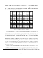
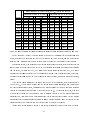
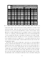
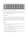
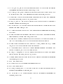
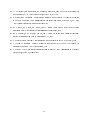
Table 3: Range coverages for trapped charge with surface voltage varying betweenVDD and GND
Table 4 shows that the eect of the die surface voltage is pretty signicant on the coverage numbers.
Again, we would like to emphasize that ISCAS85 layouts have only 2 metal layers, and this is an expected
result for them. Designs with more metal layers will not be as sensitive to die surface voltage variation.
As described earlier, if the magnitude of the trapped charge range gets larger, then the coverage of this
range by stuck-at vectors is expected to get better. We ran our simulator using the parameters for column 6
and 7 in Table 3, but using the [-1.0V, 1.0V] range for the trapped charge instead of the [-0.5V, 0.5V] range.
The range coverage numbers for the l-FW opens increased between 4 and 9 percentage points, as expected.
The range coverage numbers for the s-FW opens stayed almost the same, which were almost full coverage,
anyway.
If the trapped charge bounds stay the same while the VDD voltage decreases, then the net eect will
be as if the VDD voltage stayed the same and the trapped charge bounds increased, which actually helps
the trapped charge range coverage, as discussed above. Here we assume that the logic and IDDQ threshold
voltages of the standard cells scale down at the same rate as the VDD voltage does. However, if the ratio
of the distance between the logic-0 and logic-1 IDDQ threshold voltages to the VDD value decreases with
decreasing VDD , then this will have a diminishing eect on the range coverage of IDDQ vectors. Further
experiments can be performed using our simulator using a process technology and a cell library that are
designed for lower VDD to nd out how the coverage of IDDQ vectors will be aected.
In case IDDQ vectors cannot be applied at high speed, the number of IDDQ vectors might be limited.
21