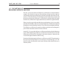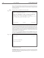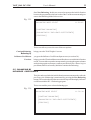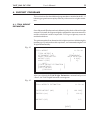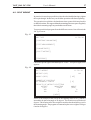
1
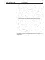
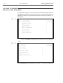
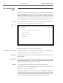
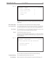
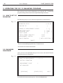
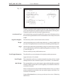
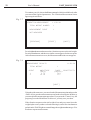
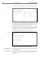
BALANCING SOFTWARE FOR THE DC-12M VIBRATION ANALYZER Ver. 3.79 USER'S MANUAL Copyright © 2000, 2004 Inteltech Enterprises, Inc. Copyright © 2000, 2004 VAST, Inc. VAST_BAL DC-12M User's Manual CONTENTS 1. BALANCING BASICS .................................................................................. 2 1.1. INTRODUCTION ................................................................................. 2 1.2. WHAT IS A MACHINE UNBALANCE? .................................................. 3 1.3. BALANCING ....................................................................................... 3 1.4. SINGLE PLANE AND MULTIPLANE UNBALANCE .................................. 4 1.5. THE METHOD OF BALANCING WEIGHTS ANALYSIS ............................ 5 2. DC-12 BALANCING PECULIARITIES ............................................................ 6 2.1. BALANCING STEPS OVERVIEW ........................................................... 6 2.2. HOW TO PREPARE THE DC-12 FOR BALANCING ................................ 8 2.3. SAVING YOUR DATA ......................................................................... 10 2.4. BALANCING SETUP OVERVIEW ......................................................... 12 2.5. VIBRATION MEASUREMENTS ........................................................... 15 2.6. ATTACHMENT OF THE TRIAL AND CORRECTION WEIGHTS............... 16 3. OPERATING THE DC-12 BALANCING PROGRAM ...................................... 18 3.1. HOW TO SET UP BALANCING ........................................................... 18 3.2. BALANCING PROCEDURE ................................................................ 18 3.3. TRIM BALANCING ............................................................................ 28 3.4. FINISH BALANCING .......................................................................... 29 3.5. BALANCING BY INFLUENCE COEFFICIENTS ..................................... 33 4. SUPPORT PROGRAMS ............................................................................. 35 4.1. TRIAL WEIGHT ESTIMATION ............................................................. 35 4.2. SPLIT WEIGHT .................................................................................. 37 4.3. SUM WEIGHTS ................................................................................. 38 APPENDIX 1................................................................................................. 39 HOW TO USE THE VAST PT-1 PHOTOPROBE FOR BALANCING MEASUREMENTS ................................................... 39 APPENDIX 2................................................................................................. 40 APPLICATION SOFTWARE TO LOAD THE BALANCING PROGRAM TO THE DATA COLLECTOR ................................................................. 40 APPENDIX 3................................................................................................. 41 APPLICATION SOFTWARE TO LOAD AND STORE BALANCING REPORTS.. 41 1 2 User's Manual VAST_BAL DC-12M 1. BALANCING BASICS 1.1. INTRODUCTION This manual describes the balancing procedure using the DC-12 data collector . This instrument's inner balancing program can be very useful for balancing rotors with up to 3 balancing planes (or weight attachment planes) and up to 8 measurement points. Aside from computation of balancing parameters (weight and angle magnitudes) the software provides the following automatic monitoring of measurement parameters and measurement accuracy; continuous automatic monitoring of the tacho signal along with initerrupting measurement process if the signal gets unstable. estimation of vibration response to the trial weights at each measurement point; automatic test for balancing planes which are equal by vibration response and exluding one of them from calculation. Balancing by three non-equal planes; balancing using only necessary balancing planes but not maximum number of them; computation of the expected viration response to the calculated corrective weights; balancing is possible even though a harmonic noise is present at frequency resolution of 0.01 per cent. balancing by the known influence coefficients (trim balancing with no trial runs). balancing both by the known influence coefficients and trial weights at once. balancing with trial weights either removed or left in place. You may select one of the above after measurement data on the trial weight is available. preliminary estimation of trial weights by the parameters of the machine under balancing; optional keyboard input for measurement data; splitting the correction weights if impossible to place the calculated weight at the determined mounting angle; adding the weights mounted at the same plane; balancing reporting. VAST_BAL DC-12M User's Manual 3 1.2. WHAT IS A MACHINE UNBALANCE? Unbalance of a rotating part of the machine is uneven mass distribution, the offset between the shaft center of mass and center of rotation. While rotating, any masses are influenced by inertial forces, but without unbalance those forces are compensated. When unbalance occurs, these forces are not fully compensated and the rotor is influenced by the forces at operating speed of the machine. Unbalance is the nature of any rotating object and is present always. Therefore, in engineering there is a distinction between acceptable unbalance when a machine can be operated and the excessive one that leads to defects and the defect development and may cause a machine failure. Balancing is the procedure for correction of the latter. Worth to mention that as well as you reduce vabration by balancing you increase rotor loading that may cause its failure. The rotor unbalance can be detected by the presence of a great component of machine vibration at its operating speed. Acceptable unbalance in different machine types is considerably depending on their dimensions and type, support and bearing stiffness, and the machine operation modes. The operation modes may differ by rotating speeds, loads and temperature conditions. One of the common causes for the excessive vibration at the rotation frequency is bend shaft line, shaft misalignment and some other defects. Hence before balancing it is recommended to check couplings, shaft line, and fix the problems since their presence makes balancing impossible. 1.3. BALANCING Whenever possible, a machine ought to be balanced at its operation speed. If not, choose the closest to that. You must avoid balancing at critical shaft speeds because the measurements of magnitude and phase taken under these conditions are inaccurate and cannot provide effective balancing. When balancing fans, pumps and turbines, it is strongly recommended to clean them up before you start balancing procedure. After that you may sometimes find that unbalance disappeared. 4 User's Manual VAST_BAL DC-12M 1.4. SINGLE PLANE AND MULTIPLANE UNBALANCE The single plane unbalance is usually called the static unbalance. This type of unbalance can be illustrated by an unbalanced disk placed on the balanced shaft in two bearing supports as shown in the next figure. Fig. 1.1 Single-plane unbalance Multiplane unbalance can be referred to as the dynamic one because it occurs only during rotation. It occurs, for example, when two disks at two different planes create a couple of forces that generate vibration. The figure below shows an example of the dual plane unbalance. Fig. 1.2 Dual plane unbalance VAST_BAL DC-12M User's Manual 5 1.5. THE METHOD OF BALANCING WEIGHTS ANALYSIS The DC-12 uses the method of influence coefficients to calculate balance weights. The vibration response of the machine to the given trial weight are calculated for all measurement points, first at the first plane, then at the second, and so on. Thus the influence of each balance plane is taken into account in all the measurement points. Influence coefficients are calculated after the initial machine run (without trial weights) and trial runs (with trial weights attached). If there is no big repair of the machine between balancing cycles, it is possible to balance the machine with one run using the influence coefficients computed during the previous balancing. It may be a very efficient for multiplane balancing. The influence coefficients are complex numbers and both real and imaginary parts of them should be stored for each coefficient. On the DC-12's screen the influence coefficients are displayed in the balancing report. While balancing by influence coefficients, the operator has to enter the balancing coefficients for each plane in the same sequence, otherwise the correction weight calculation will be wrong. Note that while balancing by influence coefficients you MUST attach tacho in the same location and position as it was in the previous balancing cycle. The mark for tacho also should be in the same location of the shaft (better use a stationary mark). 6 User's Manual VAST_BAL DC-12M 2. DC-12 BALANCING PECULIARITIES This chapter covers main steps of the field balancing using the DC-12's balancing software including computation of balancing weights. 2.1. BALANCING STEPS OVERVIEW Balancing a machine with the DC-12 inner software involves the following essential operations: 1. Prepare the places in all measurement points to mount the accelerometer. Place the phase reference mark on the rotating part of the machine and attach the phase reference tacho probe. 2. Check the tacho signal with the command Tacho Test from Applications menu. This allows you to view the tacho signal in the oscilloscope mode. The pulses must be evently spaced. If the signal is not stable, it is recommended to change the tacho mounting (shift it relative to the shaft or horizon). 3. Set up vibration measurements (amplitude and phase of vibration at the rotation frequency, rotational speed). 4. Take measurement data of initial vibration in all measurement points (prior to trial weight mounting). 5. Place the first trial weight. 6. Measure the vibration parameters at all the selected control points with the trial weight attached. 7. Proceed with calculations of the corrective weight. 8. By the calculated value of efficiency (in this program, the estimated vibration level is the maximum vibration value in all measurement points) make a decision on whether terminating trial runs and going to the correction weight mounting, or mount the next trial weight if the estimation is more than needed. 9. If you make decision to continue the trial runs, place the next trial weight and repeat the previous steps. 10.After you are satisfied with the estimated balancing efficiency or you have done all trial runs (placed all trial weights in all possible planes - at most 3), attach the determined corrective weights. VAST_BAL DC-12M User's Manual 7 11.Measure vibration parameters in all points. By the measurement data the program computes the additional correction weights and vibration response to them. Make decision on the basis of the computation whether to finish at all, or start the new balancing cycle, or continue to measure after mounting the calculated weights. If expectancy is great enough (vibration would be reduced 1.5-2 times), you may mount calculated weights and take mesurement data once again as well as calculation of correction weights and balancing efficiency. If the expectancy is small, you may z terminate the balancing cycle with the current machine (while the number of measurement points is greater than the number of balancing planes, the balancing efficiency is limited even theoretically), z continue mounting trial weights if there balance planes yet unused. z make one more full balancing cycle including trial runs with new trial weights. The reason for the later case may be the measurement errors or the dependance of the machine mechanical parameters on vibration magnitude. The DC-12 balancing program features include balancing by known influence coefficients. If influence coefficients of the machine under balancing are known, for example, recorded during previous balancing cycle and the machine was not repaired considerably, it can be balanced without trial runs. Note also that the tacho mark should be on the same place. To do this, select the Balancing by Known Influence Coefficients after the initial vibration measurements made. Enter the influence coefficients for each plane and corrective weights will be calculated. The detailed description of the balancing procedure with the DC-12 is presented below. 8 User's Manual VAST_BAL DC-12M 2.2. HOW TO PREPARE THE DC-12 FOR BALANCING An unpleasant surprise is if your instrument would automatically switch off during balancing. The data obtained would be lost, and the balancing cycle should be re-started. So you need make some precautions. Get to the DC-12 Main Menu. Fig. 2.1 DC-12 MAIN MENU 11:50:34 [CHOOSE ROUTE ] [OFF ROUTE ] [DATA TRANSFER ] [UTILITIES ] [APPLICATIONS ] Choose theUtilities command by the up/down arrow keys and press <Enter>. Fig. 2.2 UTILITIES 11:50:34 [SETTINGS ] [DELETE ROUTE ] [CALIBRATION ] [ABOUT THE DC-12 ] Select Settingson the screen and press <Enter>. The next screen appears. VAST_BAL DC-12M User's Manual 9 Fig. 2.3 SETTINGS 11:50:34 [TIME/DATE ] [RS-232 SETUP ] [POWER SUPPLY ] [DISPLAY AND KEYBOARD ] [MEASUREMENT MODES ] [TRANSDUCER ] Choose Power Management and press <Enter> to display the Power Management screen. Fig. 2.4 POWER MANAGEMENT 11:50:34 AUTO SHUT DOWN, min [20] AMPLIFIERS SWITCH OFF [ON] BATTERY CAPACITY 5 h 56 min CHARGED BATTERY CAPACITY 8 h 0 min OPERATING TIME 17 h 36 min [CHANGE ACCESS RIGHTS] Set Auto Shut Down to No by the right-left arrow buttons. In this mode, the instrument should be switch off only manually. To do so, use the <Power> key. It displays the menu for saving your data as it is described in the next section. 10 User's Manual VAST_BAL DC-12M 2.3. SAVING YOUR DATA From above it is apparent that it is important to save your data in the nonvolatile memory during balancing with DC-12. The software provides you with choices after pressing either the <Power> or <Cancel> keys. These keys are used to power down or go to the Main Menu but preliminarily you may save your data. Pressing the <Power> key during balancing displays the Shut Down screen. Note If you hold down the <Power> key more longer you cause the device to switch off and any balancing information will be lost. Fig. 2.5 SHUT DOWN 11:50:34 [SAVE STATUS & SWITCH OFF ] [SWITCH OFF ] [SAVE STATUS ] [CANCEL ] Using the up/down arrow keys, choose an options: Save Status & Switch off Use this command to save all data and switch off the DC-12. Next time when you switch it on, the screen is displayed you exit from. Switch off Use this command in case you want to switch off the DC-12 but not to save your balancing data. Save Status Use this command to save all data to nonvolatile memory of the instrument without switching off the DC-12 itself. You may use this command to backup your data at times to be sure they cannot be lost. Cancel You escape to the screen where you try to switch off the device. If you have interrupt the balancing application by the <Cancel> key, the Balancing--Cancel screen displayed. Typically, by using the <Cancel> on the DC-12, you exit the current program, i.e. balancing. In order not to loose essential data, you will be prompted first to save the measured and entered data. These data can be used later if you are not finished balancing a machine and may wish to continue balancing. VAST_BAL DC-12M User's Manual 11 Fig. 2.6 BALANCING -- CANCEL 11:50:34 [EXIT TO MAIN MENU ] [SAVE STATUS & EXIT ] [SAVE STATUS ] [CANCEL ] Using the up/down arrow keys, select the command of interest and press the <Enter> key. Exit to Main Menu The command to exit to the Applications menu without saving data. Save Status & Exit It saves balancing data and exit to the main menu of the DC-12. In balancing, you will be back to the screen where you have pressed theCancel button. Save Status The command allows you to save balancing data and go back to your previous screen. You may use the command to back up your data. Cancel You will be back to the previous screen. After you saves the balancing data using the <Power> or <Cancel> key and run the balancing program (Application Menu/Balancing) once again, the screen is displayed as follows: Fig. 2.7 BALANCING - STARTUP MODE 11:50:34 PREVIOUS BALANCING CYCLE WAS INTERRUPTED [CONTINUE BALANCING ] [NEW BALANCING ] The screen allows you to make your choice between the following Continue balancing New balancing The command to go back to the previous screen. By the command you will be prompted to set up the new balancing cycle. 12 User's Manual VAST_BAL DC-12M 2.4. BALANCING SETUP OVERVIEW To set up the DC-12 for balancing, select the Application command from the main menu of DC-12. To do it, usethe up/down arrow keys and press <Enter>. Then selectBalancingfrom the Application menu. Fig. 2.9 APPLICATIONS MENU 11:50:34 [MESSAGES ] [TACHO MONITOR ] [BALANCING ] [BALANCING LOGS ] [VECTOR CALCULATOR ] [REMOTE CONTROL ] Since you pressed <Enter >, the Balancing Setup screen appears. Fig. 2.10 BALANCING SETUP 11:50:34 MACHINE ID [ ] NUMBER OF MEASUREMENT POINTS AMPLITUDE UNITS DETECTOR ROTATION SPEED [ 1] m/s2 PEAK Hz ] ] ] [ WITH ROTATION ] [ [ [ TACHO SIGNAL ANALYSIS MEASUREMENT CONTROL ANGLE READING DIR. AUTO AUTO [NEXT] This dialog is used to setup a new balancing operation. Here you can enter the name of the machine to be balanced as well as parameters of measurement and balancing weight attachment. During balancing measurements the DC-12 uses automatic analysis of the tacho and vibration signals. As soon as the desired measurement accuracy will be achieved, the measurements will be stopped or warning messages will be issued. Here you can set the following parameters: VAST_BAL DC-12M Machine ID User's Manual 13 A machine name may contain up to characters. Use the alphanumeric keys to enter the machine name. Each of the keys has 4 characters that scroll while pressed. For example, to enter "1", press the 1 key once, to enter "A", press 1 key twice, etc. Use the left arrow for backspace and the right arrow to move to the next character. Number of Measurement Points This is the number of points at which you will measure the vibration amplitude. The number can be entered from the keypad or changed by using left/right keys. Amplitude Units Using the left/right arrows, choose the units you prefer for amplitude representation. Choices are: G, m/s2 , mm/s,υm, in/s, mils. Detector With the left/right arrows choose the detector to be used for graph representation, either RMS (Root Mean Square), Peak, or Peak-to-Peak. Rotation Speed Using the left/right arrow keys, select the units for rotation speed: Hz, RPM (revolution per minute), RPS (revolution per second - equals to Hz). Tacho Signal Analysis is set only to Auto during balancing measurements. You can read more about this setting in the DC-12 manual, phase measurements section. This mode provides that the quality of tacho signal will be analyzed. In the case of poore signal one of the following messages may be displayed at the bottom of the Vibration Measurement screen. RPM is out of range it means that the current machine rotation speed is not within the range of 60 through 100000 RPM No synchronization there is no signal from the tacho probe. The reason for it may be bad tacho probe placing or bad mark attached to the shaft or tacho is not connected to the DC-12. Recommendation is to change the tacho position or direction. Unstable synchronization there is a random signal or signals per shat revolution. Measurement Control MANUAL. The mode allows to produce up to 2000 averages of the measured parameters. The measurement process is interrupted manually with the <Enter> key. AUTO. The measurement quality and possible errors are analyzed automatically during measurements. Then the following messages are displayed depending on the results of the analysis. Required accuracy was obtained When the intended measurement accuracy is achieved, the measurement process will be automatically stopped. 14 User's Manual VAST_BAL DC-12M If the intended measurement accuracy is not achieved, the measurement process will be stopped automatically after 30 averages. After that, the DC-12 suggests a possible cause of measurement inaccuracy such as: Random noise detected Harmonics noise detected If measurement process is interrupted by the operator, the following message is displayed. Measurement is stopped If less than 3 readings have been taken, they whould be skipped. Angle Reading Dir. Using the left/right arrow keys, you can select an angle reading direction, with or against rotation. The angle readings are used for trial and balancing weight attachment. After you set up the measurements, selectNext and press <Enter> to accept your settings and continue the balancing procedure. The Point-Channel screen will be displayed. Fig. 2.10 POINT 1 2 3 4 5 6 7 8 CHANNEL [ 1] [ 1] [ 1] [ 1] [PREVIOUS] 11:50:34 [NEXT] The screen is used for a multi-channel adapter to set one-to-one correspondence between measurement points and channels. Since there is no indication at Vibration Measurement screen for any channel number, it is recommended to use the same channel numbers as for measurement points. Note that one channel may be also used to access several points. Attention! This software version assumes that sensor sensitivities are the same and equal to the one chosen in the Transducer sectionof the Settings menu (Main menu>Utilities->Settings). If one-channel adapter is used those settings are scipped. VAST_BAL DC-12M User's Manual 15 2.5. VIBRATION MEASUREMENTS This is one of the general balancing screen. It is used to measure amplitude and phase parameters at machine operating speed as well as the current rotation speed. This is one of the general balancing screen. It is used to display the vibration measurement status. During measurement, the mean amplitude and phase values are displayed together with the current rotation speed and the number of averages done. Displayed are the balancing step (for examle, Initial Vibration) and the number of a measurement point. Fig. 2.11 VIBRATION MEASUREMENT 11:50:34 INITIAL VIBRATION MEASUREMENT POINT 1 NOT MEASURED [PREVIOUS] [START] NEXT The current balancing stage is shown by indications Initial Vibration or Trial Weight N (where N is the number of a balance plane) or Test Measurement N (where N is the number of a test measurement) as well as the measurement poit number. The measurement parameters are represented by magnitude and phase and running speed values. The number of averages obtained is also shown. The automatic analysis of the input signal parameters is performed during the measurement. In the case of deviation from the required quality of the signal from the tachometer or the vibration transducer, the message appears. By default, the measurement is stopped automatically as soon as the required accuracy of the readings is achieved. In this case, the following message appears - “Required accuracy was obtained”. To check signal quality after a manual break, the signal variance is shown in per cent. The commands at the screen bottom can be selected by the left/right, up/down arrow keys and provide the following operations: 16 User's Manual Start/Stop Previous Next VAST_BAL DC-12M The command to start/interrupt measurement process. Use this button to go to the previous screen. Brings you to the next measurement screen or a screen to select a job. The screen allows you to enter data with the keyboard. To do so, press the up arrow. To navigate between fields, use the up/down arrows. Then press <Enter> to set focus on theNext command. 2.6. ATTACHMENT OF THE TRIAL AND CORRECTION WEIGHTS This section covers the common balancing problems that occurs during weight attachment. There is a large range of weight attachment types and they are not considered here. The DC-12 balancing program provides two kind of placing trial weights - with or without removing the previous one. That is any trial weight can be removed or left in place. Important! It is recommended to remove all trial weights before placing correction weights because the program computes them just for that case. If the trial weights cannot be removed due to some inconveniences, the value and mounting angle of a correction weight must be calculated with regard to the trial weight remained in the given plane. To do this, use theSum Weightssubprogram (see section 4.3). You go to this subprogram from the Job Type screen which is displayed after correction weight calculation. Fig. 2.12 JOB TYPE [CONTINUE BALANCING] [TEST MEASUREMENT] [SUM WEIGHTS] [SPLIT WEIGHT] [PREVIOUS] 11:50:34 VAST_BAL DC-12M User's Manual 17 The utility allows you to calculate parameters of the required correction weight. To do so, - select the calculated correction weight as the first part of the summed. - select the trial weight left in place as the second part of the summed. Note that to put a minus sign before it, you need to press the dot key <џџџ•>. The computed weight should be attached as the correction one. 18 User's Manual VAST_BAL DC-12M 3. OPERATING THE DC-12 BALANCING PROGRAM This section covers an entire balancing cycle using the DC-12 balancing program starting from measurement setup to balancing conclusion. 3.1. HOW TO SET UP BALANCING The Balancing Setup screen with selected parameters is shown below. Fig. 3.1 BALANCING SETUP 11:50:34 MACHINE ID [ ] NUMBER OF MEASUREMENT POINTS [ 1] AMPLITUDE UNITS DETECTOR TYPE SHAFT SPEED [ [ [ TACHO SIGNAL ANALYSIS MEASUREMENT CONTROL m/s2 PEAK Hz ] ] ] AUTO AUTO ANGLE READING [ WITH ROTATION ] [NEXT] The next command displays the Point - Channel screen. See Section 2.4 for more information. 3.2. BALANCING PROCEDURE After you have selected Next in the previous screen, the initial Vibration Measurement screen is displayed Fig. 3.2 VIBRATION MEASUREMENTS 11:50:34 INITIAL VIBRATION MEASUREMENT POINT 1 NOT MEASURED [PREVIOUS] [START/STOP] To initialize the measurement process, choose theStartbutton. NEXT VAST_BAL DC-12M User's Manual 19 The same screen after the measurement made: Fig. 3.3 VIBRATION MEASUREMENT 11:50:34 INITIAL VIBRATION MEASUREMENT POINT: AMPLITUDE ( PHASE (˜ SPEED ( m/s2 DEG Hz 1 ) ) ) 1.029 1 49.09 MESSAGES [PREVIOUS] [START] [NEXT] The screen shows the numerical value of the vibration vector at the current measurement point. If needed, you may interrupt the measurement process with the Start/Stop command. To proceed with an iterrupted measurement use the same command. To check signal quality after a manual break, the signal variance is shown in per cent. The screen allows you also to enter data with the keyboard. To set focus on an input field, use the up/down arrows, then enter you data. On conclusion, press the <Enter> key to select the Next command. After the measurement is automatically finished - if no messages were on either measurement errors or inaccuracy - you must press theNextbutton. The similar screen will be displayed for the next point now. If you need to view the previous measurements, press the Previous button. After the initial vibration data are taken, the Vibration Measurement Results screen will be displayed to show all the data. Fig. 3.4 VIBRATION MEASUREMENT RESULTS 11:50:34 INITIAL VIBRATION POINT # [1] AMPLITUDE ( m/s2 ) 1.029 PHASE (DEG) 1 [NEXT] SPEED ( Hz ) 49.09 20 User's Manual VAST_BAL DC-12M This dialog displays the vibration parameters in all measurement points. You can repeat vibration measurements at any point. To do this, use the arrow up/down keys to select the measurement point and press the <Enter> key to go to the measurement screen for the selected measurement point. The <Cancel> key brings you to the main menu and allows you to save data prior to it. The Nextcommand displays the Balancing Mode Select screen. Fig. 3.5 BALANCING MODE SELECT 11:50:34 [CONTINUE BALANCING] [BALANCING BY INFLUENCE COEFFICIENTS] [PREVIOUS] This screen is for choosing a job to proceed. Now, you can decide whether to proceed through the full balancing cycle with trial runs or, if you know the influence coefficients, for this specific machine, you can proceed balancing by using influence coefficients without trial runs. In the latter case, you have to place the phase reference tacho and mark for it at the same place of the shaft as they were when you recorded the influence coefficients. Continue Balancing Balancing by Influence Coefficients Previous Use this command to proceed with balancing - enter the parameters of trial weights and start trial runs. Use this command to enter the influence coefficients for this machine and calculate correction weights without trial runs. (See section 3.4). This command is used to revert to the previous window - Initial vibration measurement results. If you selected theContinue Balancingcommand, the Trial Weight screen is displayed. VAST_BAL DC-12M User's Manual 21 Fig. 3.6 TRIAL WEIGHT TRIAL WEIGHT # ATTACHMENT TYPE ANGLE READING DIR. WEIGHT (GR) ANGLE (DEG) 11:50:34 1 [TEMPORARY] WITH ROTATION [ 0.000] [ 0] NEXT [TRIAL WEIGHT ESTIMATION ] [SUM WEIGHTS ] [SPLIT WEIGHT ] [PREVIOUS ] You have to stop the machine and place the trial weight. This dialog box allows you to enter the parameters of trial weights to be mounted in the selected plane. Using the keypad, enter the following weight parameters Attachment Type Angle Reading Dir. select whether the current trial weight will be removed or left in place prior to the next trial weight attachment. It is recommended to remove the previous trial weight. The direction you have selected is shown for reference. Weight can be measured in grams, as well as in any other unit, e.g. volume, length (if you use rods). The important factor is to use the same units during a balancing cycle. Angle enter the angle of the trial weight mounting (in degrees) relative to the zero mark. It is recommended to use the trial weight mounting point as a reference. To do so, enter the angle = 0. There are utilities you may call from this screen: Trial Weight Estimation The utility allows you to estimate a trial weight by machine parameters. Apply toSection 4.1 for details. Sum Weights The command to replace two weights mounted at one plane with one weight which produce the same vibration response. See section 4.3 for comments. Split Weight The command allows you to split a single weight (which should be mounted at a hardly available location) into several weights by two available locations. See section 4.4 for details. This is a common case for fans and other bladed machines where you can not mount a weight between blades, but can attach weights to the blades. See section 4.2 for comments. Using the Previous button, you may go to the previous screen - Balancing Mode Select. 22 User's Manual VAST_BAL DC-12M To continue your job, choose theNextcommand, which is available only after you entered the required parameters. The Vibration Measurement screen appears again as follows. Fig. 3.7 VIBRATION MEASUREMENT 11:50:34 TRIAL WEIGHT NUMBER 1 MEASUREMENT POINT 1 NOT MEASURED [PREVIOUS] [START] [NEXT] Press theStartbutton and measure the vibration response to the trial weight. Press theNextbutton, and the next similar screen appears for the next point. After all measurements are over, the Measurement Results screen appears. Fig. 3.8 MEASUREMENT RESULTS TRIAL WEIGHT POINT 1 2 AMPLITUDE (mm/s) 5.75 13.16 11:50:34 1 PHASE SENSITIVITY (degree) 215 127 [NEXT] Using the up/down arrows, you can select the Measurement point and press the <Enter> key to go to the measurement screen for the selected point. In this way you can repeat the measurement procedure. If you press the <Cancel> key, the program goes to the Main Menu. In this case, you may save your data. If the vibration response to the trial weight is low and you want to leave the weight in place once you have selected removing it, use the Previous button to get back to the Trial Weight screen and change the weight attachment type. You need not to repeat measurements. VAST_BAL DC-12M User's Manual 23 The sensitivity column shows whether or not vibration response to the trial weight occurs at all measurement points. If not, the Low Sensitivity screen appears after you pressed the Next button. Fig. 3.9 11:50:34 LOW TRIAL WEIGHT SENSITIVITY, POSSIBLE MISALIGNMENT OR SHAFT BEND. CAN NOT CALCULATE CORRECTION WEIGHTS TRY TO INCREASE TRIAL WEIGHT AND REPEAT TRIAL RUN, OR CORRECT THE SHAFT DEFECT [REPEAT] TheRepeatbutton brings you the screen to enter trial weight parameters, the <Cancel> key allows you to go to the Main Menu. After the trial weights are mouted at the second and third planes, the check is done on balancing planes equal by vibration response. If such planes are detected, the Equal Balancing Planes screen is displayed. Fig. 3.10a EQUAL BALANCING PLANES SELECT PLANE TO COMPUTE: 11:50:34 [1ST PLANE] [2ND PLANE] [BOTH PLANES] Make your choice. Note that using both equal planes can reduce calculation accuracy and balancing efficiency. Also it can lead to mounting too big balancing weights. If you have selected one of the planes, skip the measurement data at the last plane. It allows you to work with three non-equal planes. To do so, select Both Planes and press <Enter>. Use the Previous button till you get to the Trial Weight screen. Mount the trial weight at the next plane and continue to balance. 24 User's Manual VAST_BAL DC-12M If the measurement is sufficient, the Correction Weights screen is appears. Fig. 3.10b CORRECTION WEIGHTS 11:50:34 (m/s2): ESTIMATED VIBRATION ANGLE READING DIR. 0.052 WITH ROTATION PLANE # WEIGHT (GR) 1 1.075 ANGLE (DEG) 182 [NEXT] This dialog presents the results of balancing weights calculations. Using this data, you must make a decision on whether you have to continue balancing or that the estimated result are sufficient for your machinery. Here, you see the estimated maximum vibration level at all points if you mount the weights listed below in the specified planes. Also displayed is the Angle reading direction you have selected in the Balancing Setup dialog. Press the Next button and the Job Type screen will be present. Fig. 3.11 JOB TYPE [ CONTINUE BALANCING] [ TEST MEASUREMENT] [ SUM WEIGHTS] [ SPLIT WEIGHTS] 11:50:34 [PREVIOUS] This screen enables you to select one of the following jobs: Continue Balancing You get to the Trial Weight screen to enter the next trial weight parameters and proceed with balancing. Test Measurement You get to the Weights Are Placed screen to take test measurement. In this case you must place the corrective weights which value must be more close to the calculated ones. VAST_BAL DC-12M User's Manual 25 Sum Weights A support program enables you to sum several weights placed at the same plane. See Section 4.3. Split Weights A support program enables you to distribute the calculated mass among the candidate places at the given plane. See Section 4.2. Selecting the Previous button, you go to the previous screen - Correction Weights (Fig. 3.10). If you have chosenTest Measurement, the Actual Weights Attached screen appears. Fig. 3.12 ACTUAL WEIGHTS ATTACHED PLANE # 1 11:50:34 WEIGHT (GR) [ ANGLE (˜DEG) 0.000] [ [PREVIOUS] 0] [NEXT] In this screen you have to enter with keyboard the actual parameters of the trial weights placed - Weight and Angle which can differ from the calculated. Using thePreviousbutton, you may go to the previous screen - Job Type (Fig. 3.11). Press theNextbutton, and the Vibration Measurement screen appears and the measurement process starts. Fig. 3.13 VIBRATION MEASUREMENT 11:50:34 TEST MEASUREMENT MEASUREMENT POINT: 1 NOT MEASURED [PREVIOUS] [START] [NEXT] 26 User's Manual VAST_BAL DC-12M Below you can see the same screen after the measurement made. Fig. 3.14 VIBRATION MEASUREMENT 11:50:34 TEST MEASUREMENT MEASUREMENT POINT: 1 AVERAGE NUMBER: 4 AMPLITUDE PHASE SPEED ( (˜ ( m/s2 ): DEG ) Hz ): MESSAGES [PREVIOUS] [START] [NEXT] Displayed are the results of vibration measurement after the corrective weights have been placed. After the measurement made, the Measurement Results screen appears. Fig. 3.15 MEASUREMENT RESULTS 11:50:34 TEST MEASUREMENTS SPEED POINT 1 2 (RPM) 3000 AMPLITUDE (m/s2) 5.75 13.16 PHASE (DEG) 215 127 [NEXT] Using the up/down arrows, you can select the Measurement point and press the <Enter> key to go to the measurement screen for the selected point. So you can repeat the measurement procedure. If you press the <Cancel> key, the program goes to the Main Menu. In this case, you may save your data. After you pressed theNext button, the program goes to the Job Type screen. VAST_BAL DC-12M User's Manual 27 Fig. 3.16 JOB TYPE 11:50:34 [TRIM-BALANCING] [FINISH ] [PREVIOUS] This screen provides you to select from the following options: Trim-balancing If the intended balancing efficiency have not be achieved, you can increase it by this command. The command calls the Correction Weights screen, which displays the weights to be placed to increase efficiency. There may be several steps of Trim-balancing. See Section 3.3. Finish terminates balancing and process its results. The program goes to the Balancing Report (see Section 3.4), which contains several screens. By theNextbutton you can view over each screenful. Using the Previous button you can go back to the Measurement Results screen. 28 User's Manual VAST_BAL DC-12M 3.3. TRIM BALANCING Trim balancing is a correction of the balancing weights value. It is performed after the balancing made and balancing weights attached. It is not required to place the trial weights as well as the trial runs at all. This job can be chosen from the Balancing Mode Select screen after the test measurement is taken. Fig. 3.17 BALANCING MODE SELECT 11:50:34 [TRIM-BALANCING] [FINISH] If you have selected this mode, the Correction Weights screen would appear. Fig. 3.18 CORRECTION WEIGHTS 11:50:34 ESTIMATED VIBRATION (m/s2): ANGLE READING DIR. 0.052 WITH ROTATION PLANE # WEIGHT (GR) 1 1.075 ANGLE (DEG) 182 [NEXT] This screen displays the correction weights calculated by the program. To proceed with balancing, place the weights which actual value must be much more close to the calculated. Pressing theNextbutton displays the Balancing Mode Select screen appears. VAST_BAL DC-12M User's Manual 29 Fig. 3.19 BALANCING MODE SELECT 11:50:34 CONTINUE BALANCING [TEST MEASUREMENT] [SUM WEIGHT] [SPLIT WEIGHT] Continue Balancingis not available. The DC-12 program made balancing by cycle. Each cycle begin either with balancing or with balancing by influence coefficients and continue through trim-balancing. To begin new balancing, you need to finish your job by theTest Measurementcommand. After the test measurement made and Report presentation the Job Type screen appears (see Fig. 3.28) through which you can start new balancing cycle. In this case the test measurement results will be considered as the initial vibration one. By using the Test Measurement command you may repeat trim-balancing (up to 5 times) or go to the new balancing. 3.4. FINISH BALANCING To end up the balancing cycle, chooseFinishfrom the Job Type screen (Fig. 3.16). You will be enabled to view over a Balancing Report,which contains several screens. By theNext button you can view over each screenful. All the data entered or obtained during this balancing cycle will be present in the report. An example of this is shown in the next figures. Fig. 3.20 BALANCING REPORT 11:50:34 DATE: 05-02-98 MACHINE ID: NUMBER OF MEAS. POINTS NUMBER OF PLANES AMPLITUDE UNITS DETECTOR ROTATION SPEED ANGLE UNITS ANGLE READING DIR. ROTATION SPEED [PREVIOUS] 444 1 1 um RMS RPM DEG WITH ROTATION 9520.97 (RPM) [NEXT] 30 User's Manual VAST_BAL DC-12M Fig. 3.21 INITIAL VIBRATION POINT # 1 18:27:53 AMPLITUDE (um) 29.264 PHASE (DEG) 2 [PREVIOUS] [NEXT] Fig. 3.22 TRIAL WEIGHT NUMBER 1 WEIGHT 300.000; POINT # 1 18:30:30 ANGLE AMPLITUDE (um) 7.101 [PREVIOUS] 5; TEMPORARY PHASE (DEG) 356 [NEXT] Fig. 3.23 CORRECTION WEIGHTS 18:33:38 PLANE No 1 ANGLE 2 [PREVIOUS] WEIGHT 359.131 [NEXT] VAST_BAL DC-12M User's Manual 31 Fig. 3.24 ACTUAL WEIGHTS ATTACHED 18:34:52 PLANE No 1 ANGLE 0 WEIGHT 2.000 [PREVIOUS] [NEXT] Fig. 3.25 TEST MEASUREMENT 1 POINT # 1 [PREVIOUS] 18:36:52 AMPLITUDE 7.138 PHASE 6 [NEXT] Fig. 3.26 INFLUENCE COEFFICIENTS 18:37:54 PLANE No. 1 1 [PREVIOUS] -1.041e-01 -7.332e-05 [NEXT] This screen shows the influence coefficients which have been calculated during the balancing for each weight attached. 32 User's Manual VAST_BAL DC-12M These coefficient should be saved to balance the given machine by the known influence coefficients (without trial runs). It can be made by writing down them or printing the report. Note Keep the order of coefficients to be successful. Fig. 3.27 END OF BALANCING REPORT 18:37:58 YOU JUST REACHED THE END OF BALANCING REPORT. NOW YOU CAN CHOOSE "SAVE" OPTION TO SAVE THE REPORT FOR FUTURE USE UNDER THE NAME "bal002.log". YOU CAN PRINT IT OR VIEW AT HOST PC USING DEDICATED SOFTWARE TOOLS. [PREVIOUS] [SAVE] [DISCARD] Once you pressed theSavebutton, the report will be saved as File “bal001.log”. The data collector can store a number of reports which is differed by an order number. For example, you can save reports of sequential balancing cycles for the given machine. See Section 1.2 of Appendix 1 for information on the storing and printing the reports using the PC. After you view over the Balancing Report, and select theSave button to save the report or theDiscardbutton to don't save it, the Job Type screen appears. Fig. 3.28 JOB TYPE 11:50:34 [FINISH BALANCING] [NEW BALANCING] Using this screen, you may: Finish Balancing- the balancing for the given machine is terminated, and the current data are deleted excluding the balancing report. The program goes to the Balancing Setup screen. VAST_BAL DC-12M User's Manual 33 Start New Balancing. In this case, no need to measure the initial vibration because the program takes the last results of the Test Measurement and go at once to the Balancing Mode Select screen: Fig. 3.29 BALANCING MODE SELECT 11:50:45 [CONTINUE BALANCING] [BALANCING BY INFLUENCE COEFFICIENTS] [PREVIOUS] This screen allows you to select one of the next options: Continue Balancing Balancing by Influence Coefficients Previous brings you to the Trial Weight # 1 screen. you get to the Influence Coefficients Input screen (see section 3.4). brings you to the Vibration Measurement Results screen with initial vibration results. You can either repeat the measurement by pressing the up arrow button and selecting a point to measure (confirm your choice by the <Enter> key) or pressNext, which is selected by default to continue the balancing. 3.5. BALANCING BY INFLUENCE COEFFICIENTS This job can be used after the initial vibration measurement made or after the previous cycle of balancing is terminated (by pressing theNew Balancing button). This section describes the succession of steps of balancing by influence coefficients with the DC-12 balancing program. This screen enables you to select a balancing type: Fig. 3.30 BALANCING MODE SELECT 11:50:34 [CONTINUE BALANCING] [BALANCING BY INFLUENCE COEFFICIENTS] [PREVIOUS] 34 User's Manual VAST_BAL DC-12M SelectBalancing by Influence Coefficientsand press <Enter>. The Influence Coefficients Input screen appears. Fig. 3.31 INFLUENCE COEFFICIENTS INPUT 11:50:34 PLANE NUMBER 1 1 [ 0.000e+00] [ 0.000e+00] [PREVIOUS] [NEXT ] [CALCULATE] In this screen, you can enter the influences coefficients that have been saved for this machine. The order of coefficients must be the same as it was in the Influence Coefficients screen of the Report (Fig. 3.26). To go to the next plane, press theNextbutton. You can return to the previous screen by thePreviousbutton. To confirm your input, press theCalculatebutton. The Correction Weights screen appears. Fig. 3.32 CORRECTION WEIGHTS 11:50:34 ESTIMATED VIBRATION ( m/s2 ) ANGLE READING DIR. PLANE # WITH ROTATION WEIGHT (GR) ANGLE (DEG) 1 [NEXT] The next steps have been described in Section 3.3. VAST_BAL DC-12M User's Manual 35 4. SUPPORT PROGRAMS This section describes the additional programs that are included in the DC-12 balancing program but not employed directly with corrective weights calculation. 4.1. TRIAL WEIGHT ESTIMATION One of the most difficult operations in balancing is the choice of the trial weight amount. If it is small, the response might be comparable to a measurement error and the calculation would be impossible. Too big a weight may cause the machine breakdown. The optimum method is to determine trial weights experience in balancing this machine type. If you do not have this experience, we recommend using the Trial Weight Estimation utility. Fig. 4.1 TRIAL WEIGHT 11:50:34 TRIAL WEIGHT # ATTACHMENT TYPE ANGLE READING DIR. WEIGHT (GR) ANGLE (DEG) 1 [TEMPORARY] WITH ROTATION [ 0.000] [ 0] NEXT [TRIAL WEIGHT ESTIMATION ] [SUM WEIGHTS ] [SPLIT WEIGHT ] [PREVIOUS ] After you selected the Trial Weight Estimation command and pressed <Enter>, the Trial Weight Estimation screen appears. Fig. 4.2 TRIAL WEIGHTS ESTIMATION 11:50:34 ROTOR WEIGHT (KG) [ 100.000] RADIUS (mm) [ 100.0] WEIGHT (GR) 0.5 [NEXT] 36 User's Manual VAST_BAL DC-12M For calculation you need to enter two parameters with the keypad: Rotor Weight Radius enter the rough estimate of the rotor weight in kg. enter the radius of the trial weight attachment points in mm, i.e. the distance between rotor axis and weight mounting place. Put in these data and press <Enter>. In the Weight line, the calculated value appears of trial weight in g. After that you can change your inputted data and repeat calculation. Press the Next button and you will be back in the Trial Weight screen to proceed with balancing. Note that to do the more precise calculation of the trial weight you must follow the rules below: - If the machine foundation is rigid (for example by the anchor bolts), then the calculated mass need to be magnified twice. - If the machine is mounted on the damping support, then the calculated mass is close to the optimum. - If you balance the rotor without the stator (on the balancing machine), then the calculated mass need to be divided by two. VAST_BAL DC-12M User's Manual 37 4.2. SPLIT WEIGHT In practice it is not always possible to place the calculated balancing weight at the required angle. In this case you need the operation called mass splitting. The operation is to split the calculated mass in two parts which are placed in available locations. It is supposed that the mounting places are spaced regularly that is their mounting angle step and radius are the same. You can go to this subprogram from the different screens. One of them is the Job Type screen. Fig. 4.3 JOB TYPE 11:50:34 [CONTINUE BALANCING] [TEST MEASUREMENT] [SUM WEIGHTS] [SPLIT WEIGHT] [PREVIOUS] Choose the Split Weight command and press <Enter>. The Split Weight screen appears. Fig. 4.4 SPLIT WEIGHT 11:50:34 WEIGHT (GR) 141 ANGLE (DEG) [ 45] NUMBER OF POSSIBLE ATTACHMENT PLACES [ 3] RESULTS OF WEIGHT SPLITTING WEIGHT MOUNTING (GR) PLACE 100 1 100 2 ANGLE (DEG) 0 90 [NEXT] Above is an example of the screen on the splitting mass of 141 g which is intended to be placed at angle of 45 degrees. The locations are spaced at 90 degrees. The location of the first weight is considered as the arbitrary zero for the mounting angle. The program recommend to place two weights of 100 g at 0 and at 90 degrees. 38 User's Manual VAST_BAL DC-12M 4.3. SUM WEIGHTS In practice, there are often cases when several corrective weights are mounted at one plane. That is for example when one machine has been balanced several times. To sum all such weights into one, the Sum Weights subprogram is used. In the DC-12 balancing program the weights are added by two. To add more than two weights, the action must be repeated. You go to this subprogram from the Job Type screen. Fig. 4.5 JOB TYPE 11:50:34 [CONTINUE BALANCING] [TEST MEASUREMENT] [SUM WEIGHTS] [SPLIT WEIGHT] [PREVIOUS] Choose the Sum Weights command from this screen and press <Enter>. The Sum Weights screen appears. Fig. 4.6 SUM WEIGHTS 11:50:34 WEIGHT (GR) ANGLE (DEG) WEIGHT 1 [ WEIGHT 2 [ 100] 100] SUM 141 [ [ 0] 90] 45 [NEXT] You can see above an example of addition with one weight of 100 g, 90 degrees and another weight of 100 g, 0 degrees. The program recommends to mount the summary weight of 141 g at 45 degrees. VAST_BAL DC-12M User's Manual 39 APPENDIX 1 HOW TO USE THE VAST PT-1 PHOTOPROBE FOR BALANCING MEASUREMENTS To measure vibration parameters with the DC-12, the VAST PT-1 photoprobe is available for use as an auxiliary equipment. It is shown in Fig. below. Fig. A1. Cabling this probe to the DC-12, use the Tacho input on the input panel of the device. This input is also used to power the photoprobe, thus it is not required additional power supply. On the rear panel of the photoprobe, there is a status led. While the probe transfers a signal, the led is lighting that indicates the proper state and mounting of the probe. 40 User's Manual VAST_BAL DC-12M APPENDIX 2 APPLICATION SOFTWARE TO LOAD THE BALANCING PROGRAM TO THE DATA COLLECTOR The application software is installed onto the PC and provide loading the balancing program onto the DC-12. It consist of ProgramDC__sfx.exe which unpacks the file while you start setup and creates program files dcle.exe, dclr.exe, dclwe.exeand dclwr.exein the program folder. The letter meaning is dcl data collector w the program works under Windows-95 r russian version e english version. Warning To provide security, the balancing software would be work only with the DC-12 of the given serial number. Using the program with another DC12 would be a frustrated experience. To load the software after you addressed VAST, Inc and received it, just follow the instructions on the screen. VAST_BAL DC-12M User's Manual 41 APPENDIX 3 APPLICATION SOFTWARE TO LOAD AND STORE BALANCING REPORTS To provide unloading the reports from the DC-12 to the host computer, their printing and storage, you need the Rus.110 Application software. The software works under Windows-95. To install it, just follow the instruction appeared on the screen.