1
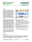
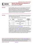
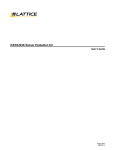
Broaddown2 User Manual
Issue – 1.02
© Enterpoint Ltd. - Broaddown2 M anual – Issue 1.02 06/08/2005
Kit Contents
You should receive the following items with you Broaddown2 development kit:
1 - Broaddown2 Board
Figure 1 - Broaddown2 Board
© Enterpoint Ltd. - Broaddown2 M anual – Issue 1.02 06/08/2005
Foreword
PLEASE READ ALL OF THIS MANUAL BEFORE PLUGGING IN
OR POWERING UP YOUR BROADDOWN2. PLEASE TAKE
SPECIAL NOTE OF THE WARNINGS WITHIN THE MANUAL.
Trademarks
Coolrunner-II, Spartan-3, ISE, EDK, Webpack, Xilinx are the registered trademarks of Xilinx Inc,
San Jose, California, U S.
M oel-Bryn, Broaddown2 are trademarks of Enterpoint Ltd.
© Enterpoint Ltd. - Broaddown2 M anual – Issue 1.02 06/08/2005
Introduction
Welcome to your Broaddown2 the “Ultimate Spartan-3 Development Board”.
Broaddown2 is a member of Enterpoint’s Moel-Bryn product range and offers a
highly flexible approach to prototyping FPGA and System designs.
The aim of this manual is assist in using the main features of Broaddown2. There are
features such as regulator shutdown control and advanced programming features that
are beyond the scope of this edition of the manual. Should you have a need to use
these features then please contact the support email [email protected] for
detailed instructions to use these advanced features.
Broaddown2 comes in 3 principal variants based on the size of FPGA fitted. The
Spartan-3 fitted can either be XC3S400-4FG456C, XC3S1000-4FG456C, or
XC3S1500-4FG456C. Should you need the faster -5, industrial or automotive grade
FPGA’s fitted to a board please contact Enterpoint sales for a quote.
In addition to these principal variants Broaddown-2 has build options for LVDS
termination resistors and YFS connectors. Please contact sales for a quote if you
require these options.
Broaddown2 modules that are now available to purchase:
A/D Converter (DIL Header Module)
Low Cost Programming Cable (Standalone)
SODIMM I/O Expansion Module
PCI I/O Expansion Module
RS232 Module
RS485 Module
USB2 Module
LED 4 Segment Display Module
PS2 Module
Ethernet Phy Module
AD7202 Module
We can also offer custom DIL Header modules should you require a function not
covered by our current range of modules. Typical turn around for this service is 2-4
weeks if parts can be obtained in time.
© Enterpoint Ltd. - Broaddown2 M anual – Issue 1.02 06/08/2005
Finding Your Way Around
Figure 2 - Front Side of Broaddown2
Figure 3 - Back Side of Broaddown2
© Enterpoint Ltd. - Broaddown2 M anual – Issue 1.02 06/08/2005
Getting Started
Your Broaddown2 will be supplied pre-programmed with a test design. A default setting of jumpers
will also be fitted. The test design will allow the user to determine that most of the major elements
of the Broaddown2 are working. To use this test you must do the following:
(1) Ensure that the LHS DIL Power Selector is set at the 3.3V position (factory default).
(3) Connect the Broaddown2 to your power source (un-powered) by the disk drive power connector
or by plugging into a PCI slot within a Personal Computer (un-powered). Please note that plugging
into a Personal Computer should only be done by an experienced system administrator. As with the
addition of any new element to a computer there is a possibility that plugging your Broaddown2
into a computer PCI slot may cause data corruption or loss. You should ensure that adequate
backups of data or systems are made before attempting this step. If you do not have a valid PCI
supporting design loaded in the FPGA on the board it is likely to freeze the supporting computer.
(4) Switch on your power source.
Figure 4 - Broaddown2 with LED/USB Module and DIP Switch fitted.
The flash memory/s can be re-programmed at any time using the appropriate JTAG interface. You
will need a JTAG programming cable PROG1/2, or Xilinx Parallel IV, or Xilinx USB programming
cables (flying leads needed) together with Xilinx ISE tools to re-program the Platform Flash
devices.
© Enterpoint Ltd. - Broaddown2 M anual – Issue 1.02 06/08/2005
Broaddown2 Features
Power Inputs
Broaddown2 can take current from either the PCI edge connector or the Disk Drive Connector at
the top left of the card. The power supplies on the PCI edge connector can be isolated by jumpers
J24 and J30 should a power supply contention issue arise. It is recommended that for currents
greater than 2 amps on the 5V input and 0.5 amp on the 12V rail then the disk drive connector
should be used.
The principal input to Broaddown2 is the 5V input. The 12V input is only used to feed the Negative
Voltage Rail circuits and for the M oel-Bryn expansion position.
Reset-able poly-fuses are fitted to both the 5V and 12V inputs. Respective notional ratings of 7
amps and 3 amps are the limits of power input. The actual trip currents of these devices will vary
with cooling and ambient temperature and hence the operational cut-offs may be much lower that
these figures.
WARNING – THE POLY-FUSES CAN GET VERY HOT IN
NORMAL OPERATION. PLEASE DO NOT TOUCH OR PLACE
HIGHLY FLAMABLE MATERIALS NEAR THESE DEVICES
WHILST THE BROADDOWN2 IS IN OPERATION.
© Enterpoint Ltd. - Broaddown2 M anual – Issue 1.02 06/08/2005
Power Pickups
Figure 5 - Broaddown2 Power Pickup Points
WARNING – DO NOT CONNECT ANY VOLTAGE HIGHER
THAT 3.3V TO THE SPARTAN-3 I/O PINS. TAKE GREAT CARE
THAN CIRCUITS POWERED FROM VOLTAGES HIGHER THAN
3.3V DO NOT DRIVE SIGNALS CONNECTED TO SPARTAN-3 TO
A SIGNALLING VOLTAGE GREATER THAN 3.3V.
Broaddown2 has power pickup points. Each pickup normally consists of a 3 pin 2mm header
although some other types of pick-up are available on Broaddown2. The pinout of the 3 pin pickup
points is usually defined as:
Pin1
Pin2
Pin3
- Voltage O/P
- Isolated
- Gnd (0V)
In addition to these pickup points power can be picked up from LHS DIL Header, RHS DIL
Header, Bank Voltage Selector J26 and Vref Voltage Selector J15. Please see the relevant sections
for more details on these features.
© Enterpoint Ltd. - Broaddown2 M anual – Issue 1.02 06/08/2005
The voltages that are available on 3 pin pickup points are as in the following table.
Voltage
12V
5V
4.1V
3.3V
2.5V
1.8V
1.5V
1.2V
User1 Rail
Header
J34
J33
J39
J38
J37
J36
J10
J9
J7
User2 Rail
J6
© Enterpoint Ltd. - Broaddown2 M anual – Issue 1.02 06/08/2005
Note
Potentiometer socket, Pin2
not isolated
Potentiometer socket, Pin2
not isolated. Rail may need
to be turned on by CPLD
output.
Selecting FPGA Bank (Vcciox) + Main SODIMM Voltages
Broaddown2 divides the I/O pins of the fitted Spartan-3 into 7 banks. The FPGA does natively
support 8 banks however on Broaddown2 banks 6+7 share their Vccio. The key to voltage selection
and hence support I/O standards is header J26. From this header the 7 bank voltages and SODIMM
main voltages can individually be selected from 3V, 2.5V and 1.8V. Additionally 1 extra selection
is available to each output power rail. By soldering appropriate solder bridges SB170-185 1.2V or
1.5V can be made available as levels. It is also possible to set a custom level using a flying lead to
the header but the voltage supplied should be the range +1.2V to +3.45V. Please note that the
header is not pinned out the same way for each output power rail. The pinout chosen makes it
unlikely that input power rails can be shorted together using a single jumper. The header layout and
the nearby RHS DIL Power Selector are shown below.
1.8V
U SER
U SER
1.8 V
SOD
3.0V
3.0V
2.5V
2.5 V
2.5V
2.5 V
BK0
3.0V
3.0V
1.8V
U SER
BK5
U SER
U SER
1.8 V
1.8V
U SER
BK6
1.8 V
BK1
3.0V
3.0V
BK4
2.5V
2.5 V
2.5V
2.5 V
BK2
3.0V
3.0V
BK3
U SER
U SER
1.8 V
1.8V
1. 8V
3.0V
R HS
2. 5V
© Enterpoint Ltd. - Broaddown2 M anual – Issue 1.02 06/08/2005
Selecting FPGA Vref Voltages
Broaddown2 primarily supports Vref voltages for banks 2,3 and 4. It is these banks that connect to
the DDR2 SODIMM module. It may be possible to apply Vref for other banks using flying wires
but please check with support before attempting this.
The selection of Vref is carried out on header J15. Each of banks 2,3,4 can be connected by jumper
to the reference voltage supplied by the push/pull (LP2996) regulator. This regulator generates a
reference voltage half that of its input reference voltage which is the SODIMM main supply rail.
Please note that jumper setting of J8 will affect the range with which the LP2996 will regulate. For
details of this please refer to the LP2996 datasheet.
As an alternative the USER1 power rail can be used as a reference but this will not track the
SODIMM main voltage rail. V_U SER1 can be set within the range of 1.22V to 3.3V approximately
by fitting a potentiometer or resistor in socket position J7 between pins 2 and 3.
A spare selector is included on J15 should you need to pickup the LP2996 reference voltage. J15
also allows the grounding of Vref inputs to the FPGA should you need to do this. The pinout of J15
is shown below.
J8 should also normally be set to the 2V5 setting for DDR2 operation. This will allow generation of
a reference voltage of 0.9V when the main SODIMM power rail is set to 1.8V.
© Enterpoint Ltd. - Broaddown2 M anual – Issue 1.02 06/08/2005
Programming Broaddown2
JTAG
POWER CONTROL PLATFOR M
CONNECTOR
FLASH
+ PR OGRAMMING
FPGA
COOLRUNN ER -II
(FPGA
PROGRAMMIN G)
CPLDS
JTAG
CONNECTOR
CPLD
SPARTAN-3
FPGA
Figure 6 - JTAG Connector Positions
The programming of the FPGA, CPLDs and Platform Flash parts on Broaddown2 is achieved using
JTAG chains. Principally it is anticipated that a JTAG cable will be used in conjunction Xilinx ISE
software although other alternatives do exist including self re-programming.
There are 2 JTAG chains on Broaddown2. The first chain allows the programming of the three
Coolrunner-II CPLDs. Normally users will not need to reprogram these devices. However to use
special power sequencing and/or advanced programming features reprogramming of these devices
may be needed. If you are considering using these features you should study the Broaddown2
circuits and understand the full functionality before modifying the CPLD programming.
The second JTAG chain allows the programming of the Spartan-3 and Platform Flash devices as
well as the a M oel-Bryn expansion card if fitted.
Each JTAG connector has a layout is as follows:
© Enterpoint Ltd. - Broaddown2 M anual – Issue 1.02 06/08/2005
The CPLD chain looks like this:
Figure 7 - CPLD JTAG Chain
The FPGA chain looks like this:
Figure 8 - FPGA JTAG Chain
If a M oel-Bryn module supporting a JTAG programmable device is fitted then jumper J14 should
be removed.
Programming of the Spartan-3 FPGA can be achieved by direct JTAG programming or from the
Platform Flash memory/s. By default the Spartan-3 devices is programmed from the Platform Flash
memories at power up. However the default configuration mode can be altered by reprogramming
the Coolrunner-II CPLDs on Broaddown2. Direct JTAG programming is volatile and the FPGA
will lose its configuration every time the board power is cycled. From sustained use of FPGA
design programming the design into the Platform Flash memory is recommended. Generation of
suitable Platform Flash content files and control of the JTAG chain can be achieved using the
XILINX ISE tool IMPACT.
© Enterpoint Ltd. - Broaddown2 M anual – Issue 1.02 06/08/2005
Primary Voltage Regulators
Figure 9 - Primary Power Regulator Features
Broaddown2 has a power backbone based on four TPS75901 linear regulators. These regulators are
capable of delivering 7.5 amps. The structure of these four regulators is a semi-chain so that
effectively all the current taken out of the chain passes through the top regulator (4.1V) and any
intermediate chain regulators. Therefore the absolute maximum current that can be delivered into
Broaddown2 is limited to 7.5 amps.
The output voltages of this chain are 4.1V, 3.3V, 2.5V and 1.8V. Practically the current delivered
by the regulator chain will be limited by the RGE500 reset-able fuse that is fitted on 5V input to the
regulator chain. From practical experience and testing the following total current can be delivered in
the primary regulators under the following cooling conditions.
Cooling
No Forced Cooling
Simple Fan Fitted To M ounts
Special Cooling
Approximate Board Input Current Limit
3 Amps
5 Amps
7.5 Amps
With the exception of the 4.1V regulator each Primary Regulator has a zero ohm resistors on input
supply and on regulator output. It is possible using these resistors to break the chain to allow
measurement of individual currents. These features can also be used where more complex power
sequencing needs to be modelled or if a switching regulator input needs to be substituted.
© Enterpoint Ltd. - Broaddown2 M anual – Issue 1.02 06/08/2005
Secondary Power Regulators
Figure 10 - Secondary Power Regulators
Broaddown2 has a number of secondary regulators. These regulators are derived from twin
regulator devices TPS70402. These regulators will deliver 1 or 2 amps depending on which section
of the TPS70402 is being used. The following voltage rails are derived using these regulators.
DEVICE CURRENT RATING O/P SERIES RESISTOR
Vccaux (SPARTAN-3)
U2
1 AM P
NO
Vccint (SPARTAN-3)
U2
2 AM P
YES
Vccaux2 (NOT USED)
U3
1 AM P
NO
1.5V
U3
2 AM P
YES
USER1
U4
1 AM P
YES
USER2
U4
2 AM P
YES
VOLTAGE
Current measurement can be achieved by replacing a zero resistor with a low ohm sense resistor
where the above table indicates a suitable resistor position.
A separate TPS70402 (U14) is also fitted to Broaddown2 for the supply of the Coolrunner-II
CPLDs. This device operates independently of the main and secondary regulator chains.
As these regulators are variable regulators rail voltages can be modified to suit particular voltage
applications if necessary. The minimum that the TPS70402 will regulate to is 1.22V.
© Enterpoint Ltd. - Broaddown2 M anual – Issue 1.02 06/08/2005
Negative Rail Generation + Selection
Broaddown2 has 2 inverting LT1054 charge pump regulators fitted. Each regulator will deliver
about 100 mA and the two outputs can be connected together to give a single 200 mA supply. The
regulators are operated in simple inverting mode and do not offer much in regulation in this mode.
If you need tight regulation, or low noise, you should fit a post regulator to improve these
parameters.
The LT1054 regulators will deliver the approximate inverse of their input voltages. Selection
headers J31 and J32 allow the selection of 12V, 5V and 3V as input voltages by jumper.
Alternatively different voltages can be feed into the LT1054 by flying wire to J31/ J32 to give other
voltages. The LT1054 fitted has a maximum input of 15V and a technical minimum of 3.5V.
Enterpoint has found that input voltages lower than 3.5V do work in practise but operation of the
LT1054 is not guaranteed at these levels. The pinout of J31 and J32 is as follows.
Figure 11 - Negative Voltage Regulators Input Selection (J31 / J32)
J28 header allows the selection of voltages that are to be feed to the M oel-Bryn expansion module.
This header also acts as a pickup point for these supplies and users can connect their flying lead
connections to this header.
© Enterpoint Ltd. - Broaddown2 M anual – Issue 1.02 06/08/2005
SODIMM Socket
Figure 12 - SODIMM Features
WARNING – DO NOT INSERT A DDR1 SODIMM INTO THE
DDR2 SODIMM SOCKET. IT WILL SHORT OUT THE POWER
SUPPLIES.
CURRENTLY WE ARE NOT SUPPORTING MEMORY BASED
SODIMMS IN THIS SOCKET. THE DETAILS IN THIS SECTION
ARE FOR YOUR INFORMATION ONLY.
Broaddown2 has a DDR2 SODIMM socket allowing the fitting of a I/O expansion module
Figure 13 - SODIMM I/O Module
The SODIMM I/O M odule can also be used to support loopback testing of the SODIMM Socket
when used in conjunction with a suitable test build loaded into the Spartan-3 FPGA.
The SODIMM Socket is keyed and will only support DDR2 style SODIMM modules. DDR2
SODIMM module pinout is incompatible with DDR1 SODIMM pinout. Do not remove the
© Enterpoint Ltd. - Broaddown2 M anual – Issue 1.02 06/08/2005
mechanical key to allow DDR1 modules to fit. If non-memory modules are fitted then the Socket
can supply alternative voltages of 3.3V, 2.5V or 1.8V by jumper selection. Other voltages available
by flying wire. Please note that the relevant Spartan-3 Bank voltages should be set appropriately for
whichever voltage is used. In addition do exceed the Spartan-3 maximum I/O voltages. A 0 to 3.3V
signalling (4.05V absolute max) is the maximum normal range of signalling that Spartan-3 can
tolerate.
When used for a DDR2 (currently not supported) memory function the following signal features are
available:
(1) 32 bit data (upper 32 bit not available)
(2) A0 TO A13 address
(3) BA0 to BA2 bank address
(4) DM 0 to DM 3
(5) CK0, CK1
(6) CKE0, CKE1
(7) RAS
(8) CAS
(9) CS0, CS1
Because the data bus has been narrowed from 64 bit to 32 bit any standard DDR2 SODIMM fitted
with effectively only have half its stated capacity. Peak data rate of 200 MHz (100 MHz clock) are
to be expected.
The signals of the SODIMM Socket have been connected to banks 2, 3, 4 of the Spartan-3 FPGA.
To use a DDR2 module you will need to set the relevant Vcciox (bank) and Vref (reference)
voltages to 1.8V and SODIMM reference voltage respectively. Track lengths between the
SODIMM Socket and the Spartan-3 have been matched as closely as is practical to minimise signal
skew.
SODIMM configuration prom reading is supported indirectly. It is directly wired to a Coolrunner-II
CPLD U11 and can be accessed by the Spartan-3 FPGA via the CPLD Expansion Bus. This feature
is not automatically enabled when you Broaddown2 is delivered and you should contact support
[email protected] if this feature is needed.
The LP2996 regulator will provide a +/- 1.5 amp termination voltage at half the SODIMM main
voltage input. J8 allows the power input voltage of the LP2996 to be set to either 2.5V or 3.3V. For
DDR2 voltage levels operation the jumper should be fitted between pins 1 and 2 to select 2.5V
input supply.
To select the main SODIMM voltage rail please refer to the section on Bank Voltage Selection.
© Enterpoint Ltd. - Broaddown2 M anual – Issue 1.02 06/08/2005
PCI Edge Connector
Figure 14 - Broaddown2 PCI Interface Features
WARNING – BROADDOWN2 HAS BEEN DOUBLE KEYED TO
ALLOW USE IN BOTH 3.3V AND 5V PCI SOCKETS. IT IS
POSSIBLE TO PLUG BROADDOWN2 INTO THE PCI SOCKET
BACKWARDS OR DISPLACED. IF A BROADDOWN2 IS
INSERTED INCORRECTLY AND POWERED THE
BROADDOWN2, AND HOST SYSTEM, WILL BE DAMAGED.
PC POWER SUPPLIES OFFER VERY LITTLE PROTECTION
AND WE HAVE SEEN POWER SUPPLY LEADS MELT AND
CATCH FIRE UNDER SHORT CIRCUIT CIRCUMSTANCES.
TAKE EXTRA CARE TO ENSURE BROADDOWN2 IS INSERTED
CORRECTLY.
Broaddown2 has been design to work in both 3.3V and 5V PCI systems. For this interface to work
as a PCI interface you will need to buy, or design, a suitable FPGA PCI logic circuit or IP core.
Broaddown2 will be supplied with test builds containing a PCI IP core and other cores for your
evaluation and use. We are hoping to release our own low cost Target Only PCI Core shortly.
Broaddown2 supports a 32 bit, 33 MHz, implementation of PCI.
The pinout of the Spartan-3 FPGA has been chosen such that the PCI interface follows the Xilinx
PCI IP core (XC3S400-4FG456C pinout). FPGA pin numbers are available on the customer
schematics. Our current test builds use the Xilinx PCI core.
© Enterpoint Ltd. - Broaddown2 M anual – Issue 1.02 06/08/2005
The Spartan-3 FPGA has an absolute input voltage maximum of 4.05V (3.3V signalling). To allow
use in 5V PCI systems we have added Bus Switch parts IDTQS32X681 between the PCI Edge
Connector and the Spartan-3 FPGA. These parts limit the voltage seen by the Spartan-3 FPGA.
Technically addition of these parts make the interface non-compliant with the PCI specification.
However in practise this implementation of the interface has no operation issues.
If you don’t want to use the PCI Edge Connector for PCI and run Broaddown2 standalone you can
use the Disk Drive Power Connector to power the board. Using the optional PCI I/O Expansion
M odule you can use PCI interface as general I/O.
Figure 15 - PCI I/O Expansion Module
If you need 5V input tolerant I/O and don’t need PCI then, then using this module is an easy way of
achieving this. The Bus Switches on Broaddown2, fitted for 5V PCI tolerance, work as well for
general 5V input signals. The timing penalty, i.e. through propagation, of the Bus Switches is
approximately 250 pico-seconds.
© Enterpoint Ltd. - Broaddown2 M anual – Issue 1.02 06/08/2005
Right Hand Side DIL Header
The RHS DIL Header provides a simple mechanical and electrical interface for add-on modules.
The connectors on this header are on a 0.1 inch, 2.54 mm, pitch and allow either custom modules,
stripboard or even dil style components (3.3V/2.5V only) to be fitted. The RHS DIL Header
supports modules and components with horizontal lead pitches of 0.3, 0.4, and 0.6 inch pitches.
The header has a permanent positive power pin at the top position of the right column. It also has
Gnd (0V) at the bottom of left column of the header. It is also possible to connect any right column
to the RHS DIL Power Rail by means of solder bridges on the back of the Broaddown2. Similarly
the any position on the left column can be connected to Gnd. If any of the solder bridges are made
then the user should ensure that the Spartan-2 FPGA does not attempt to drive the relevant pin.
Failure to do so may damage the Broaddown2.
The RHS DIL Power Rail can be selected by jumper to 3.3V, 2.5V or 1.8V. Alternatively other
supplies can be connected to the selector by flying wire. It is advised that voltages outside 0 to 3.3V
are not used unless special precautions are taken to protect Spartan-3 I/Os. The Spartan-3 has an
absolute input voltage rating of 4.05V. The pinout of the selection header is as follows:
© Enterpoint Ltd. - Broaddown2 M anual – Issue 1.02 06/08/2005
In the current version of Broaddown2 only the 31 pins of this header are available as active signals
connected to the Spartan-3. These active signals are located on left column positions 2 to 16
counting from bottom and on the right column positions 1 to 16 counting from bottom. The Spartan
-3 pinout connections are shown in the following table as is LVDS pair support.
LEFT COLUMN
LEFT
COLUMN
POSITION
1
2
3
4
5
6
7
8
9
10
11
12
13
14
15
16
17
18
19
20
21
22
23
24
25
26
27
28
29
30
31
32
33
34
SPARTAN3 PIN
NOT USED
NOT USED
NOT USED
NOT USED
NOT USED
NOT USED
NOT USED
NOT USED
NOT USED
NOT USED
NOT USED
NOT USED
NOT USED
NOT USED
SB
SB
SB
SB
GENERAL
GENERAL
LVDS_P
LVDS_N
LVDS_P
LVDS_N
LVDS_P
LVDS_N
LVDS_P
LVDS_N
LVDS_P
LVDS_N
LVDS_P
LVDS_N
GENERAL
GND
VCC
SB
GENERAL
LVDS_P
LVDS_P
GND
RIGHT COLUMN
SPARTAN3 PIN
VCC
U11
U10
V11
W11
W10
Y10
V9
W9
V8
W8
V6
W6
W5
Y5
V10
GND
AB11
V7
AA10
AB10
AA9
AB9
AA8
AB8
Y6
AA6
AA4
AB4
AA3
Y4
U7
U6
RHS DIL
VCC
NOT USED
NOT USED
NOT USED
NOT USED
NOT USED
NOT USED
NOT USED
NOT USED
NOT USED
NOT USED
NOT USED
NOT USED
NOT USED
SB
SB
SB
SB
GENERAL
GENERAL
LVDS_P
LVDS_N
LVDS_P
LVDS_N
LVDS_P
LVDS_N
LVDS_P
LVDS_N
LVDS_P
LVDS_N
LVDS_P
LVDS_N
GENERAL
GENERAL
- Power
- Special Function
- General Spartan-3 I/O
- LVDS Pair With Termniator Resistor Site
- LVDS Pair Without Termniator Resistor Site
- Gnd (0V)
© Enterpoint Ltd. - Broaddown2 M anual – Issue 1.02 06/08/2005
RIGHT
COLUMN
POSITION
1
2
3
4
5
6
7
8
9
10
11
12
13
14
15
16
17
18
19
20
21
22
23
24
25
26
27
28
29
30
31
32
33
34
The signals marker as LVDS_P and LVD S_N are routed such that the trace lengths approximately
match and skew is minimised within pair. Adjacent LVDS_P and LVDS_N form the matched pair
at the RHS DIL Header and the Spartan-3 FPGA. For example V11 and W11 form one pair.
LVDS pairs marked as with terminating resistor site can be used as LVD S inputs to the Spartan-3
when the resistor is fitted. All LVDS pairs can be used as outputs from Spartan-3. The resistors are
0201 size and are located on the back of Broaddown2 underneath the Spartan-3 FPGA.
When not used as LVDS signals can be used as general I/O subject to Bank Voltage Vccio5’s
setting and standards mixture. All I/O in positions19 to 34, left and right columns, connect to Bank5
of the FPGA.
Special Function pins are for advanced JTAG and M oel-Bryn programming support and their use is
currently beyond the scope of this manual.
© Enterpoint Ltd. - Broaddown2 M anual – Issue 1.02 06/08/2005
LHS DIL Header + Card Edge Connector
The LHS DIL Header provides a simple mechanical and electrical interface for add-on modules.
The connectors on this header are on a 0.1 inch, 2.54 mm, pitch and allow either custom modules,
stripboard or even dil style components (3.3V/2.5V only) to be fitted. The LHS DIL Header
supports modules and components with horizontal lead pitches of 0.3, 0.4, and 0.6 and 1.6 inch
pitches.
The header has a permanent positive power pin at the top position of the right column. It also has
Gnd (0V) at the bottom, and top, of left column of the header. It is also possible to connect any right
column to the RHS DIL Power Rail by means of solder bridges on the back of the Broaddown2.
Similarly the any position on the left column can be connected to Gnd. If any of the solder bridges
are made then the user should ensure that the Spartan-2 FPGA does not attempt to drive the relevant
pin. Failure to do so may damage the Broaddown2.
The LHS DIL Power Rail can be selected by jumper to 3.3V, 2.5V or 1.8V. Alternatively other
supplies can be connected to the selector by flying wire. It is advised that voltages outside 0 to 3.3V
are not used unless special precautions are taken to protect Spartan-3 I/Os. The Spartan-3 has an
absolute input voltage rating of 4.05V. The pinout of the selection header is as follows:
© Enterpoint Ltd. - Broaddown2 M anual – Issue 1.02 06/08/2005
The LHS DIL Header Spartan-3 pinout connections are shown in the following table as is LVDS
pair support.
LEFT COLUMN
LEFT
COLUMN
POSITION
1
2
3
4
5
6
7
8
9
10
11
12
13
14
15
16
17
18
19
20
21
22
23
24
25
26
27
28
29
30
31
32
33
34
RIGHT COLUMN
GND
SPARTAN3 PIN
GND
SPARTAN3 PIN
VCC
GENERAL
GENERAL
GENERAL
LVDS_P
LVDS_N
LVDS_P
LVDS_N
LVDS_P
LVDS_N
LVDS_P
LVDS_N
LVDS_P
LVDS_N
LVDS_P
LVDS_N
LVDS_P
LVDS_N
LVDS_P
LVDS_N
LVDS_P
LVDS_N
LVDS_P
LVDS_N
LVDS_P
LVDS_N
LVDS_P
LVDS_N
LVDS_P
LVDS_N
GENERAL
GENERAL
GENERAL
GND
A12
A10
D10
B19
A19
B18
A18
C17
B17
A15
B15
B14
A14
B13
A13
C12
B12
C11
D11
B10
C10
A9
B9
A8
B8
B6
C6
A5
B5
D9
C7
A3
GND
F14
F17
F16
E16
E13
D18
C18
E17
D17
E15
D15
E14
D14
D13
C13
E12
D12
E11
F11
E10
F10
E9
F9
D7
E7
D6
E6
C5
D5
F13
F12
F7
F6
LHS DIL VCC
XC3S1000/1500
ONLY
GENERAL
GENERAL
GENERAL
GENERAL
LVDS_P
LVDS_N
LVDS_P
LVDS_N
LVDS_P
LVDS_N
LVDS_P
LVDS_N
LVDS_P
LVDS_N
LVDS_P
LVDS_N
LVDS_P
LVDS_N
LVDS_P
LVDS_N
LVDS_P
LVDS_N
LVDS_P
LVDS_N
LVDS_P
LVDS_N
LVDS_P
LVDS_N
GENERAL
GENERAL
GENERAL
GENERAL
VCC
SB
- Power
- Special Function
- General Spartan-3
GENERAL I/O
LVDS_P
- LVDS Pair With Termniator Resistor Site
LVDS_P
- LVDS Pair Without Termniator Resistor Site
GND
- Gnd (0V)
M ost of these signals continue on to the Card Edge Connector for use there.
© Enterpoint Ltd. - Broaddown2 M anual – Issue 1.02 06/08/2005
RIGHT
COLUMN
POSITION
1
2
3
4
5
6
7
8
9
10
11
12
13
14
15
16
17
18
19
20
21
22
23
24
25
26
27
28
29
30
31
32
33
34
The Edge Connector shares the LHS DIL signal connections to the Spartan-3 and the same
signalling levels apply at this connector. Signalling outside the 0V to 3.3V should not be used on
this connector as it could damage the Spartan-3 which is also connected to these signals. The pinout
of the Card Edge Connector follows and is a sub-set of signals on LHS DIL Header and the signals
on the "A" row of the Card Edge Connector connect symmetrically to the left column of the LHS
DIL Header. Similarly the "B" row connects to the right column of the LHS DIL Header.
EDGE
CONNECTOR
ROW A
1
2
3
4
5
6
7
8
9
10
11
12
13
14
15
16
17
18
19
20
21
22
23
24
25
26
27
28
29
30
GENERAL
GENERAL
LVDS_P
LVDS_N
LVDS_P
LVDS_N
LVDS_P
LVDS_N
LVDS_P
LVDS_N
LVDS_P
LVDS_N
LVDS_P
LVDS_N
LVDS_P
LVDS_N
LVDS_P
LVDS_N
LVDS_P
LVDS_N
LVDS_P
LVDS_N
LVDS_P
LVDS_N
LVDS_P
LVDS_N
LVDS_P
LVDS_N
GENERAL
GENERAL
SPARTAN-3
PIN
A10
D10
B19
A19
B18
A18
C17
B17
A15
B15
B14
A14
B13
A13
C12
B12
C11
D11
B10
C10
A9
B9
A8
B8
B6
C6
A5
B5
D9
C7
SPARTAN-3
PIN
F17
F16
E16
E13
D18
C18
E17
D17
E15
D15
E14
D14
D13
C13
E12
D12
E11
F11
E10
F10
E9
F9
D7
E7
D6
E6
C5
D5
F13
F12
GENERAL
LVDS_P
LVDS_P
- General Spartan-3 I/O
- LVDS Pair With Termniator Resistor Site
- LVDS Pair Without Termniator Resistor Site
GENERAL
GENERAL
GENERAL
GENERAL
LVDS_P
LVDS_N
LVDS_P
LVDS_N
LVDS_P
LVDS_N
LVDS_P
LVDS_N
LVDS_P
LVDS_N
LVDS_P
LVDS_N
LVDS_P
LVDS_N
LVDS_P
LVDS_N
LVDS_P
LVDS_N
LVDS_P
LVDS_N
LVDS_P
LVDS_N
LVDS_P
LVDS_N
GENERAL
GENERAL
EDGE
CONNECTOR
ROW B
1
2
3
4
5
6
7
8
9
10
11
12
13
14
15
16
17
18
19
20
21
22
23
24
25
26
27
28
29
30
If you wish to have power and Gnd on this connector then you will need to use the solder bridges of
the LHS DIL Header to make the necessary connections. Spartan-3 voltage limits apply.
© Enterpoint Ltd. - Broaddown2 M anual – Issue 1.02 06/08/2005
The signals marker as LVDS_P and LVD S_N are routed such that the trace lengths approximately
match and skew is minimised within pair. Adjacent LVDS_P and LVDS_N form the matched pair
at the LHS DIL Header and the Spartan-3 FPGA. For example B19 and A19 form one pair.
LVDS pairs marked as with terminating resistor site can be used as LVD S inputs to the Spartan-3
when the resistor is fitted. All LVDS pairs can be used as outputs from Spartan-3. The resistors are
0201 size and are located on the back of Broaddown2 underneath the Spartan-3 FPGA.
When not used as LVDS signals can be used as general I/O. The I/O on this header connects to
Banks 0 and 1 of the Spartan-3 FPGA. Supported I/O standards will be determined by Vccio0 or
Vccio1 Bank Voltages and the Spartan-3 banking rules. Please note that the PCI clock input from
the PCI Edge Connector is connected to pin B11 which is in Bank0. If this input is to operate
correctly then this may limit the Bank0 Vccio0 to being 3.3V and hence may limit the standards that
can be supported by Bank0 and thence on part of the Card Edge Connector and LH S DIL Header.
© Enterpoint Ltd. - Broaddown2 M anual – Issue 1.02 06/08/2005
FPGA
Figure 16 - Broaddown2 FPGA
Broaddown2 supports Spartan-3 devices in the FG456 package. Broaddown2 is normally available
with commercial grade and -4 speed devices fitted in three sizes XC3S400, XC3S1000, and
XC3S1500. Should you have an application that needs industrial or faster speed grades please
contact sales for a quote at [email protected] Broaddown2 has two Platform Flash sites
supporting XCF02 and XCF04 devices in a daisy chain configuration. These sites allow a
programming capacity of between 2 and 8 M bits. The size and number of devices fitted will depend
which variant of Broaddown2 is ordered.
Simple switch "S1" is fitted as a reset. This is connected to one of the TPS70402 regulators (U14)
where a de-bounced and lengthened output pulse on signal "RESET_N" is generated. "RESET_N"
is connected to one of the Coolrunner-II CPLDs U9. If this switch is needed to control a function or
reset in the Spartan-3 FPGA then please use the Expansion Bus to relay the switch status to the
FPGA.
Otherwise the PCI reset signal is connected to the Spartan-3 FPGA and can be used for reset
purposes.
The two oscillator sockets on Broaddown2 support 5V, 8-pin DIL outline, oscillator modules. The
clock signals are routed through the Bus Switches and then connected to the CPLDs. "CLOCK1" is
generated by an oscillator in socket J29 the right most socket and connects to all three CPLDs U6,
U9 and U11. This clock can be used in the control of advanced programming and power control
functions. Within U11 it can also be routed to either signal "CLOCK3_P" or "CLOCK3_N" which
are connected to the Spartan-3 FPGA as clock signals. Default factory CPLD programming
connects "CLOCK1" to drive "CLOCK3_N" of the Spartan-3 FPGA (pin AA11).
© Enterpoint Ltd. - Broaddown2 M anual – Issue 1.02 06/08/2005
"CLOCK2" is generated by the left most Oscillator Socket. It only connects to CPLD U11. From
U11 it can be routed to either signal "CLOCK3_P" or "CLOCK3_N" which are connected to the
Spartan-3 FPGA. Default factory CPLD programming connects "CLOCK2" to drive "CLOCK3_P"
of the Spartan-3 FPGA (pin Y11).
If clock with a mark/space ratio of 50:50 is desirable then implementing a divide by 2 in U11 can
give an output/s on "CLOCK3_X" approximately of the desired ration. Otherwise U11 can be used
to divide down a clock or produce phased clocks if that is desirable. The Spartan-3 itself has DCM s
to produce multiples, divisions and phases of clock signals. Please consult the Spartan-3 datasheet
available from the Xilinx website at http://www.xilinx.com.
Figure 17 - DCI Solder Bridges and LVDS Termination Resistors
Broaddown2 supports the DCI feature of Spartan-3. DCI can be used to match signal impedances to
improve signal integrity. Broaddown2 supports independent DCI functions for each bank of the
Spartan-3. By default a 100 ohm resistor is connected between VRN, VRP FPGA terminals and the
appropriate power rails. It also possible to connect parallel 100 ohm resistors by solder bridge
independently on each VRN or VRP branch. The effect of connecting parallel resistors is to change
the effective resistance from 100 ohm to 50 ohm. Please refer to customer schematics for details of
solder bridge connections.
Broaddown2 supports 17 input LVDS pairs when termination resistors are fitted. A further 20 pairs
of LVDS are supported for output only on LHS and RHS DIL Headers. Other LVD S output pairs
are possible via PCI Edge Connector or the SODIMM Socket if these are not being used for their
primary functions.
Vref voltages are supported in Banks 2, 3 and 4. Please see the section on the Vref Header for
voltage selection.
© Enterpoint Ltd. - Broaddown2 M anual – Issue 1.02 06/08/2005
Moel-Bryn Expansion Position
Figure 18 - Moel Bryn Expansion
M oel-Bryn expansion uses solder-less connectors to connect modules to the Broaddown2.
Enterpoint will be releasing a series of modules shortly for this advanced expansion capability.
The details of this interface will only be released under license and may be subject to license or
royalty fee.
The associate YFS connectors allow I/O expansion over the normal Broaddown2 capabilities when
a M oel-Bryn Expansion M odule is fitted.
© Enterpoint Ltd. - Broaddown2 M anual – Issue 1.02 06/08/2005
CPLDS
POWER CONTROL
+ PROGR AMMING
C OOLR UNN ER-II
C PLDS
SPARTAN-3
FPGA
C PLD JTAG
CON NECTOR
CPLD POWER
R EGUL ATORS
OSCILL ATOR
SOCKETS
Figure 19 - Broaddown2 CPLDs
There are three Coolrunner-II XC2C32-6CP56C CPLDs fitted to Broaddown2. These CPLDs
support indirect access for the Spartan-3 FPGA to the SODIMM serial prom. These devices also
support advance programming features such driving the FPGA JTAG chain for reprogramming
purposes. The CPLDs also support control of most of the linear regulators. Using these features
either groups or individual regulators can be turned off or on. There is also support for
programming and control of the M oel-Bryn Expansion Position.
To access these features the 9 bit Expansion Bus connects the Spartan-3 FPGA to each of the
CPLDs. This bus may be used as a user wishes. However Enterpoint is developing a standard
approach to the bus use and this will be implemented in upgrades of Broaddown2. It will also be
used in future products such as Broaddown3 and Broaddown4. A future release of this manual will
provide more detail of this implementation.
The CPLDs have their own power supply in the shape of a TPD70402 twin regulator package. By
having regulators independent of the M ain and Secondary Regulators modelling of wake-up power
systems is possible. For wake up it is possible to use one of the clock inputs to the CPLDs, derived
from the oscillator sockets on Broaddown2, to switch on the regulators for Spartan-3 FPGA.
© Enterpoint Ltd. - Broaddown2 M anual – Issue 1.02 06/08/2005
Medical and Safety Critical Use
Broaddown2 is not authorised for the use in, or use in the design of, medical or other safety critical
systems without the express written person of the Board of Enterpoint. If such use is allowed the
said use will be entirely the responsibility of the user. Enterpoint Ltd will accepts no liability for
any failure or defect of the Broaddown2, or its design, when it is used in any medical or safety
critical application.
© Enterpoint Ltd. - Broaddown2 M anual – Issue 1.02 06/08/2005
Warranty
Broaddown2 comes with a 90 return to base warranty. There are a number of places that
Broaddown2 can be soldered by a user. We have sited these on the back of the board to avoid
damage to other components when solder bridges are made. However do not attempt to solder
connections if you are not competent to do so. Enterpoint reserves the right not honour a warranty if
the failure is due to poor soldering technique or other maltreatment of the Broaddown2.
Outside warranty Enterpoint offers a fixed price repair or replacement service. We reserve the right
not to offer this service where a Broaddown2 has been maltreated or otherwise deliberately
damaged. Please contact support if need to use this service.
Other specialised warranty programs can be offered to users of multiple Enterpoint products. Please
contact sales on [email protected] if you are interested in these types of warranty,
© Enterpoint Ltd. - Broaddown2 M anual – Issue 1.02 06/08/2005
Support
Enterpoint offers support during normal United Kingdom working hours 9.00am to 5.00pm. Please
examine our Broaddown2 FAQ web page and the contents of this manual before raising a support
query. We can be contacted as follows:
Telephone
Email
- +44 (0) 1684 585262
- [email protected]
© Enterpoint Ltd. - Broaddown2 M anual – Issue 1.02 06/08/2005