1
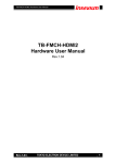
Broaddown4 User Manual
Issue – 2.00 draft
© Enterpoint Ltd. - Broaddown4 Manual – Issue 2.00 11/04/2007
Kit Contents
You should receive the following items with you Broaddown4 development kit:
1 - Broaddown4 Board
2 - Programming Cable Prog2
Figure 1 - Broaddown4 Board
Figure 2 - Prog2 Programming Cable
© Enterpoint Ltd. - Broaddown4 Manual – Issue 2.00 11/04/2007
Foreword
PLEASE READ ALL OF THIS MANUAL BEFORE PLUGGING IN
OR POWERING UP YOUR BROADDOWN4. PLEASE TAKE
SPECIAL NOTE OF THE WARNINGS WITHIN THE MANUAL.
Trademarks
Virtex-4, Spartan-3, ISE, EDK, Xilinx are the registered trademarks of Xilinx Inc, San Jose,
California, US.
Moel-Bryn, Broaddown4 are trademarks of Enterpoint Ltd.
© Enterpoint Ltd. - Broaddown4 Manual – Issue 2.00 11/04/2007
Introduction
Welcome to your Broaddown4 the “Ultimate Virtex-4 Development Board”.
Broaddown4 is a member of Enterpoint’s Moel-Bryn product range and offers a
highly flexible approach to prototyping FPGA and System designs.
The aim of this manual is to assist in using the main features of Broaddown4. There
are features such as regulator shutdown control and advanced programming features
that are beyond the scope of this edition of the manual. Should you have a need to use
these features then please contact the support email [email protected] for
detailed instructions to use these advanced features.
Broaddown4 has 2 positions for Virtex-4 devices and the capability to take 2 more
FPGAs with Swinyard1, Swinyard2 or future modules fitted to the Moel-Bryn
expansion sockets. Each Virtex-4 position can support a choice of 6 device sizes, in 3
speed grades, and in industrial and commercial temperature speed grades giving a
massive range of device combinations.
An on-board Spartan-3 FPGA is also available to handle programming structures,
power management functions, and CFCARD/SDCARD access.
A wide range of modules are available for Broaddown4 including:
Swinyard1 - Single Virtex-4 LX40-160 or SX55 with DDR2 DRAM,
Swinyard2 - Single Virtex-5 LX55-110 (coming soon),
Ethernet 10/100 Module,
Ethernet 10/100/1000 Module (coming soon),
A/D Converter Module,
Dot Matrix LED Display,
RS232 Module,
RS485 Module,
PS2 Module,
USB I/F Module,
SODIMM Expansion Header - SODIMM used as I/O
We can also offer custom variants of Broaddown4 or modules should you require a
function not covered by our current product range. Contact board sales on
[email protected] for your exact requirements.
© Enterpoint Ltd. - Broaddown4 Manual – Issue 2.00 11/04/2007
Block Diagram
The following block diagram shows the main interconnects available on
Broaddown4. Individual interfaces are described in more detail elsewhere in this
manual.
Figure 1 - Simplified Broaddown4 Block Diagram
© Enterpoint Ltd. - Broaddown4 Manual – Issue 2.00 11/04/2007
Feature Finder - Finding Your Way Around
Figure 2 - Front Side of Broaddown4
Figure 3 - Back Side of Broaddown4
Features
(1)
(2)
(3)
(4)
(5)
(6)
XC9572XL CPLD
OSCILLATOR
JTAG HEADER
LHS DIL HEADER
PLATFORM FLASH (SPARTAN-3)
JTAG HEADER
© Enterpoint Ltd. - Broaddown4 Manual – Issue 2.00 11/04/2007
(7)
(8)
(9)
(10)
(11)
(12)
(13)
(14)
(15)
(16)
(17)
(18)
(19)
(20)
(21)
(22)
(23)
(24)
(25)
(26)
(27)
(28)
(29)
(30)
(31)
(32)
(33)
(34)
(35)
(36)
(37)
(38)
(39)
(40)
(41)
(42)
(43)
(44)
(45)
(46)
VIRTEX-4 FPGA (DEVICE1)
TPS70402 REGULATOR (CPLD + SPARTAN-3)
PLATFORM FLASH (VIRTEX-4 – DEVICE1)
JTAG HEADER
CFCARD SOCKET
SPARTAN-3 FPGA (SERVICES FPGA)
OSCILLATOR
PLATFORM FLASH (DEVICE2)
JTAG HEADER
LT4600 10A REGULATOR (1.2V)
POWER MONITORING
LT4600 10A REGULATOR (1.8V)
POWER INPUT SOCKET1 (5V, 12V)
LT4600 10A REGULATOR (2.5V)
LT4600 10A REGULATOR (3.3V)
POWER INPUT SOCKET2 (5V, 12V)
RHS DIL HEADER
OSCILLATOR
VIRTEX-4 FPGA (DEVICE2)
DDR2 SDRAM BANKx DEVICE2
DDR2 SDRAM BANKx DEVICE2
ICS8442 100-700MHZ CLOCK GENERATOR
CLOCK BUFFER
DEVICE2 I/O BANK VOLTAGE SELECTOR
DEVICE1 I/O BANK VOLTAGE SELECTOR
CLOCK BUFFER
LM86 THERMAL DIODE MEASUREMENT I.C.
DDR2 SDRAM BANKx DEVICE1
NXP PA1101A PCI-E PHY
X1 PCI-E CONNECTOR
LM4600 10A REGULATOR (1.2V or 1.0V to MOEL-BRYN)
EDGE CONNECTOR
MOEL-BRYN SOCKET2
DDR2 SODIMM SOCKET DEVICE2
MOEL-BRYN SOCKET USER REGULATOR1
SDCARD/MMC CARD SOCKET
MOEL-BRYN SOCKET USER REGULATOR2
DDR2 SODIMM SOCKET DEVICE1
MOEL-BRYN SOCKET1
ENCRYPTION KEY BATTERY HOLDER
© Enterpoint Ltd. - Broaddown4 Manual – Issue 2.00 11/04/2007
Getting Started
(1) Please read the whole of this manual before starting with your board.
(2) Connect the Broaddown4 to a computer power supply (un-powered) using the disk drive type
power cables that are in most personal computers. The Broaddown4 can be operated either in X1
PCI-E slot, or stand alone on the bench, but does need both a 5V and 12V to be connected for full
operation. The PCI-E connector will not supply sufficient power for Broaddown4 to operate and the
disk drive power input must always be used even when fitted with a PC.
(3) Switch on your power source.
© Enterpoint Ltd. - Broaddown4 Manual – Issue 2.00 11/04/2007
Device1 Virtex-4 FPGA
Device1 has the following clock connections,
CLOCK CONNECTION
Cypress CLKA
Cypress CLKB
Cypress CLKC
Cypress CLKX
Cypress PECAL
PLL
PLL feedback in
PLL feedback out
DEVICE1 PIN (p)
AG17
AH17
AH18
AG18
AF16
E16
F18
K19
DEVICE1 PIN (n)
~
~
~
~
AG16
F16
G18
J19
FPGA Device1 (7) is one of Xilinx Virtex-4 FPGAs LX40, LX60, LX80, LX100, LX160 or SX55.
These devices are available in speed grades -10, -11, -12 and in both commercial and industrial
temperature grades. Enterpoint's flexible manufacturing system allows a build to order options such
that you can specify size, speed grade and temperatures options of the device that we fit in this
socket.
FPGA Device1 has interfaces to PCI-E (35/36), SODIMM1 (44), LHS DIL Header (4), EDGE
Connector (38), Moel-Bryn Socket1 (45), Device2 (25), Device3 (12) and DDR2 Bank1 (34). It is
supported by clock circuits (28/32) capable of being programmed to deliver clocks up to 700 MHz .
I/O banks 8, 9, 10, 11, 12 and 14 of Device1 can individually be jumper selected to voltages of
1.2V, 1.8V, 2.5V or 3.3V using the bank voltage selector (31).
DCI impedance matching features are available on Banks 1, 2, 5, 6, 7, 8, 9, 10, 11, 12, 13 and 14 of
Device1. Each VRN and VRP signal of these banks has 100R resistors wired appropriately.
The PCI-E interface is based on a NXP(Philips) Semiconductors PXA1101A Phy (35) and delivers
a X1 PCI-E interface. At the normal clocking rate of 2.5GHz this interface can transfer at up to 2
GBits/s of data which is a significant increase over conventional PCI interfaces. The PCI-E
interface, unlike conventional PCI, does not share the bus to/from the PCI-E slot and the loss of
bandwidth typically seen in conventional PCI is less prevalent. Structures of the PCI-E
implemented in the host personnel computer may restrict the bandwidth of the PCI-E. Discussion of
these restrictions is beyond the topic of this manual. The PCI-E logic IP is not included with
Broaddown4. A number of providers exist for this IP.
SODIMM1 (44) supports a DDR2 module of up to 2 Gbyte’s in a X64 data configuration. This
memory socket is capable of running up to TBA MHz and can deliver a memory bandwidth up to
TBA GByte/s. If not used for a memory function our optional SODIMM I/O Expansion Module
allows the use of the Device1 connections to this socket as general I/O. Enterpoint can also provide
custom modules including microprocessors or other functions in the SODIMM format.
The LHS DIL Header (4) provides a simplistic expansion capability. Enterpoint provides a range of
modules for this socket including RS232, RS485, ADV7202, IDE, ADC, CODEC, and Displays.
Up to 102 I/O are available on this header for use with modules. The header also provides power at
3.3V, 2.5V and optionally 1.8V or 1.2V.
© Enterpoint Ltd. - Broaddown4 Manual – Issue 2.00 11/04/2007
The EDGE Connector (38) provides 48 3V3 capable IO’s there is also GND, 3V3 and 2V5 power
pick up points with the POWER at the top pin1 and GND spread throughout the connector.
When Device2 (25) is fitted 76 connections to/from Device1 can support up to 38 GBit/s of data
transfer between the 2 FPGAs. The interface supports source synchronous interfaces including
compensative clock looping on the interface to correct for board level delays. The clocking
structure of Broaddown4 also support matched clocking structures to both Device1 and Device2
allowing a simpler hook up between the devices albeit at lower data rates.
CAUTION PLEASE MAKE SURE THE BANK VCCIO’s
ARE MATCHED BEFORE POWERING UP BROADDOWN4
Device3 (12) interface offers access to CFCARD, SDCARD facilities. It also can support the
programming of Device 2, The Platform Flash, and both Moel-Bryn sockets. To support these
facilities suitable designs must be implemented within Device1 and Device3 to support these
advanced features. Access to voltage and current monitoring capabilities is also possible through
this interface.
DDR2 Bank1 (34) – A single X16 DDR2 device is supported on this interface. This interface is
capable of running at TBA MHz offering up to TBA GByte/s data transfer.
Programming of Device1 can be from Platform Flash devices U12 and U13 or by JTAG cable
socket J13. The JTAG socket takes a Xilinx standard 14 pin, 2mm, ribbon cable connection.
Alternatively programming can be handled by Device3 which can be loaded with designs to support
programming data routed through Device1 – either from PCI-E interface, a source on Moel-Bryn
Socket1, a source on the LHS DIL Headers or from some algorithmic function contained in
Device1. Device3 can also support programming of data from either CFCARD or SDCARD
sockets either from memory cards inserted or via Ethernet, serial or other special network
connections host via these sockets.
Please note that reprogramming Device1 may disrupt the function of the PCI-E interface unless
special measures are taken to either store the PCI-E configuration data and to restore after reconfiguration or to cause a host system reboot.
Enterpoint does not supply IP for the enhanced Device3 programming features with the
Broaddown4 but suitable designs can be supplied to your specification at a charge. Contact board
sales [email protected] for a quote and timescale for your specific needs.
© Enterpoint Ltd. - Broaddown4 Manual – Issue 2.00 11/04/2007
Device2
Device2 has the following clock connections,
CLOCK CONNECTION
Cypress CLKA
Cypress CLKB
Cypress CLKC
Cypress CLKX
Cypress PECAL
PLL
PLL feedback in
PLL feedback out
DEVICE2 PIN (p)
AJ17
AH17
AF18
AG18
AK18
E18
G17
F18
DEVICE2 PIN (n)
~
~
~
~
AK17
E17
G16
G18
The Device2 position of Broaddown4 supports one of Xilinx Virtex-4 FPGAs LX40, LX60, LX80,
LX100, LX160 or SX55. These devices are available in speed grades -10, -11, -12 and in both
commercial and industrial temperature grades. Enterpoint's flexible manufacturing system allows a
build to order options such that you can specify size, speed grade and temperatures options of the
device that we fit in this socket.
Device2 has interfaces to SODIMM2, RHS DIL Header, Moel-Bryn Socket2, Device1, Device3,
DDR2 Bank2, and DDR2 Bank3. It is supported by clock circuits capable of being programmed to
deliver clocks up to 700 MHz .
I/O banks 8, 9, 10, 11, 12 and 14 of Device1 can individually be jumper selected to voltages of
1.2V, 1.8V, 2.5V or 3.3V.
DCI impedance matching features are available on Banks 1, 2, 5, 6, 7, 8, 9, 10, 11, 12, 13 and 14 of
Device1. Each VRN and VRP signal, of these banks, has 100R resistors wired appropriately.
SODIMM2 supports a DDR2 module of up to 2 GByte in a X64 data configuration. This memory
socket is capable of running up to TBA MHz and can deliver a memory bandwidth up to TBA
GByte/s. If not used for a memory function our optional SODIMM I/O Expansion Module allows
the use of the Device1 connections to this socket as general I/O. Enterpoint can also provide custom
modules including microprocessors or other functions in the SODIMM format.
The RHS DIL Header provides a simplistic expansion capability. Enterpoint provides a range of
modules for this socket including RS232, RS485, ADV7202, IDE, ADC, CODEC, and Displays.
Up to 68 I/O are available on this header for use with modules. The header also provides power at
3.3V. Extra I/Os are available in this header when larger devices are fitted in the Device2 position.
The PIN Grid array allows a greater expansion of the RHS DIL header providing an extra 78 IO’s
but also extra power support by providing extra GND pins but also 2V5, 1V8 and 1V2, it is
Enterpoint’s intention that this slot can support another FPGA or microprocessor module for more
dedicated purposes.
76 connections to/from Device1 can support up to 38 GBit/s of data transfer between the 2 FPGAs.
The interface supports source synchronous interfaces including compensative clock looping on the
interface to correct for board level delays. The clocking structure of Broaddown4 also support
© Enterpoint Ltd. - Broaddown4 Manual – Issue 2.00 11/04/2007
matched clocking structures to both Device1 and Device2 allowing a simpler hook up between the
devices albeit at lower data rates.
The Device3 interface offers access to CFCARD, SDCARD facilities. It also can support the
programming of Device 1, The Platform Flash, and both Moel-Bryn sockets. To support these
facilities suitable designs must be implemented within Device2 and Device3 to support these
advanced features. Access to voltage and current monitoring capabilities is also possible through
this interface.
DDR2 Bank2 – A single X16 DDR2 device is supported on this interface. This interface is capable
of running at TBA MHz offering up to TBA GByte/s data transfer.
DDR2 Bank3 – A single X16 DDR2 device is supported on this interface. This interface is capable
of running at TBA MHz offering up to TBA GByte/s data transfer.
Programming of Device2 can be from Platform Flash devices U23 and U24 or by JTAG cable
socket J20. The JTAG socket takes a Xilinx standard 14 pin, 2mm, ribbon cable connection.
Alternatively programming can be handled by Device3 which can be loaded with designs to support
programming data routed through Device1 – either from PCI-E interface, a source on Moel-Bryn
Socket1, a source on the LHS DIL Headers or from some algorithmic function contained in
Device1. Device3 can also support programming of data from either CFCARD or SDCARD
sockets either from memory cards inserted or via Ethernet, serial or other special network
connections host via these sockets.
Enterpoint does not supply IP for the enhanced Device3 programming features with the
Broaddown4 but suitable designs can be supplied to your specification at a charge. Contact board
sales [email protected] for a quote and timescale for your specific needs.
© Enterpoint Ltd. - Broaddown4 Manual – Issue 2.00 11/04/2007
Device3
Device3 has a dedicated clock which is routed to the device this is notionally 50MHz.
CLOCK SOURCE
S3_CLOCK
SPARTAN PIN
AB12
Device3 (12) is a Xilinx Spartan-3 XC3S1000/1500 FPGA. This device provides a wide range of
services to Device1 and Device2. Including CFCARD and SDCARD access, current and voltage
measurement of main power rails, and programming of Device1, Device2, Moel-Bryn Socket1 and
Moel-Bryn Socket2. To use these services a suitable design for Device3 must be loaded into the
Platform Flash (5) supporting these features.
SPARTAN JTAG SIGNALS
TCK
TMS
TDI
TDO
TDO CONNECTOR
TDO PROM 2
INT_B
PROG_B
BUSY
DONE
CCLK
HSWAP_ENABLE
READ_WRITE
CS_B
ENEXTSEL
REV_SEL0
REV_SEL1
M0
M1
M2
D0
D1
D2
D3
D4
D5
D6
D7
TCK
TMS
TDI
TDO
INT_B
DEVICE 1
E2
D1
G2
G6
P1
D2
C1
D3
F4
E1
F3
L5
L6
K2
G1
H5
F5
K3
K4
K1
F2
E3
G5
D4
C4
C3
C2
E4
MOEL BRYN SIGNALS
M3
M1
M2
N4
V2
© Enterpoint Ltd. - Broaddown4 Manual – Issue 2.00 11/04/2007
DEVICE 2
E21
D22
G21
G22
J22
E20
C21
E19
K21
G19
C22
L22
L20
L21
F21
F19
F20
L18
L17
L19
K22
E22
D21
D20
F18
D19
C20
E18
Y22
Y20
Y21
W22
N19
PROG_B
BUSY
DONE
CCLK
RESET_N
READ_WRITE
CS_B
SP1
SP2
DOUT
M0
M1
M2
M3
DIN
D1
D2
D3
D4
D5
D6
D7
CARD ID1
CARD ID2
CARD ID3
CARD ID4
CARD ID5
CARD ID6
CARD ID7
CARD ID8
W3
M5
M6
V1
M4
W2
Y3
N3
N2
N1
U5
W1
T4
Y1
T6
T5
U4
T1
U3
U2
T2
V3
L4
L1
V5
W4
Y2
V4
L2
L3
M21
W19
Y19
M22
V19
M20
M17
W21
V22
W20
U20
M19
U21
M18
V21
V20
T22
N21
T21
N22
U19
N20
K20
K19
G17
G18
R18
T18
U18
T17
CFCARD and SDCARD sockets can be used to host memory cards or other interfaces such as
Ethernet, USB, RS232, RS485 to name a few possibilities. The data delivered can be used for
programming of any of Device1, Device2, Moel-Bryn socket1 and Moel-Bryn Socket2 or can be
used as general data to support embedded microprocessors or other functions needing substantial
data.
The Device3 pins supporting the CFCARD are as follows:
FLASH MEMORY PIN
A0
A1
A2
A3
A4
A5
A6
A7
A8
SPARTAN PIN
AA8
W9
AA10
Y10
U7
V8
V10
U13
V13
© Enterpoint Ltd. - Broaddown4 Manual – Issue 2.00 11/04/2007
A9
A10
D0
D1
D2
D3
D4
D5
D6
D7
D8
D9
D10
D11
D12
D13
D14
D15
CD1
CD2
WP
WE
OE
CE1
CE2
BVD1
BVD2
REG
INPACT
RESET
WAIT
VS1
VS2
CSEL
REDY
IORD
IOWR
AB13
V14
U6
W6
AA6
W18
Y17
V16
Y16
U16
Y6
W5
AA5
Y18
AA17
W16
U17
AA15
V18
AA4
Y5
U14
Y13
W17
V17
V6
V7
V9
AA9
AA11
AB10
W14
W8
U10
U12
AA13
W13
The Device3 pins supporting the MMC/SDCARD are as follows:
MULTI-MEDIA CARD PIN
PIN1
PIN2
PIN3
PIN4
PIN5
PIN6
PIN7
SPARTAN PIN
AB18
AB15
AB14
AB11
AB9
AB8
AB5
© Enterpoint Ltd. - Broaddown4 Manual – Issue 2.00 11/04/2007
PIN8
PIN9
WRITE PROTECT1
WRITE PROTECT2
CARD DETECT1
CARD DETECT2
AB4
AA18
Y4
AA3
AB20
AA20
Device3 also hosts the serial SPI interface controlling the ADC AD7927 which measures voltage
drops over a 5mΩ on the main 3.3V, 2,5V, 1.8V and 1.2V power rails of the board. It is possible to
build a current profile for operation of the board and store the data on a memory card or using the
sockets as a network connection remotely on a hard drive etc.
ADC CHIP
CS
SCLK
DOUT
DIN
SPARTAN PIN
A5
A9
A11
A8
Device3 hosts the serial interface to control the 3 clock generators on board, the two dedicated
cypress CY22394 parts that provide 4 clocks to each individual Virtex4. The third clock generator
ICS8442 is capable of delivering 2x700MHz LVDS clock signals, these signals are fed into two
ICS8745 PLL’s, which are controlled by Device3, and should allow synchronisation of both
Virtex4 devices up to TBA MHz.
ICS8442 PIN
N0
N1
M0
M1
M2
M3
M4
M5
M6
M7
M8
PLOAD
SDATA
SLOAD
TCLK
XSEL
MR
VCOSEL
SCLOCK
ICS8745 PIN
PLL_SEL
SEL0
SPARTAN PIN
F9
E9
C11
D11
D10
E11
F11
D9
C10
F10
E10
F12
F13
E13
E15
D14
D12
E12
C12
S3 PIN FOR DEVICE1
B12
C13
© Enterpoint Ltd. - Broaddown4 Manual – Issue 2.00 11/04/2007
S3 PIN FOR DEVICE2
E16
E17
SEL1
SEL2
SEL3
MR
D13
D5
F6
B13
F17
A14
E14
F16
CY22394 PIN
SHUTDOWN
SUSPEND
SCLK
SDAT
S3 PIN FOR DEVICE1
E7
D7
E6
D6
S3 PIN FOR DEVICE2
C18
D17
D18
C19
Device3 also has control of the temperature diode sensor IC, monitoring each Virtex4’s temperature
diode embedded in each device with the alert signals routed to Device3 and the Alarm signal routed
to the CPLD.
LM86 PIN
CLK
DATA
ALERT
ALARM
S3 PIN FOR DEVICE1
C5
F7
B8
CPLD 87
S3 PIN FOR DEVICE2
B17
C17
D15
CPLD 89
Device3 also has support busses that can be programmed to do any function the user wishes, there is
a 20bit bus between the CPLD and Device3 the intention is that this bus would be used to route
regulator control and PCIE jtag pins through to Device3, a 10bit bus between Device1 and Device2
has also been routed the intention of this bus is as a way for Device1 to control the clock generation
and higher functions supported by Device3.
SPARTAN VIRTEX BUS
SB5
SB6
SB7
SB8
SB9
SB10
SB25
SB26
SB27
SB28
SPARTAN TO CPLD BUS
1
2
3
4
5
6
7
SPARTAN PIN
G3
G4
J4
H4
N6
N5
R5
P6
H1
H2
SPARTAN PIN
A4
B6
B18
A15
C6
B5
B14
© Enterpoint Ltd. - Broaddown4 Manual – Issue 2.00 11/04/2007
VITREX PIN
V27
W27
U31
U30
U27
U26
U23
T23
V32
W32
CPLD PIN
16
13
18
20
14
15
25
8
9
10
11
12
13
14
15
16
17
18
19
20
B4
A12
B15
B20
A19
A13
B11
B19
A10
A18
B9
B10
C7
17
28
23
33
36
27
29
39
30
40
3
99
4
Other functions that are supported by Device3 include regulator control for the TPS70402
regulator’s onboard the enable and reset function of these devices are routed to Device3.
TPS70402 USER RAIL
REG1 EN1
REG1 EN2
REG2 EN1
REG2 EN2
SPARTAN PIN
V12
Y12
W10
W11
© Enterpoint Ltd. - Broaddown4 Manual – Issue 2.00 11/04/2007
Broaddown4 Features
Picture - power structure.
Power Inputs
Broaddown4 takes current from the Disk Drive Connectors (19/22) at the top right of the card.
Depending on your card configuration and designs loaded into Devices1/2/3 you may need either a
single feed in or a dual feed in. Each connector is each capable of carrying 5 amps of 5V input. The
power supplies on the PCI-E edge connector are not used as they are inadequate to operate
Broaddown4.
The principal input to Broaddown4 is the 5V input. The 12V input is only used to provide a voltage
for N-Channel MOSFET gate enhancement that are used in the power protection and monitoring
circuits and the Moel-bryn connectors 12v rail.
Main Power Regulators
Broaddown4 uses 4 Linear Technology LTM4600 switching regulators to deliver current to the
main 3.3V, 2.5V, 1.8V and 1.2V rails. Each of these rails is capable of supporting 10 amps in the
basic configuration of Broaddown4. Further current capability may be possible by special build of
Broaddown4. A further LTM4600 supports the core voltages used on the Moel-Bryn sockets and
can support Swinyard1 (Virtex-4) and Swinyard2 (Virtex-5) core voltages of 1.2V and 1V
respectively to a further 10 amps capability by a resistor fit change.
Secondary Voltage Regulators
Two TPS70402 regulators U8 and U19 provide power for the Spartan-3 FPGA, XC9572XL, power
management and programming circuits.
User Voltage Regulators
TPS70402 regulators U46 and U47 provide 4 user settable rails that are available to use on the
Moel-Bryn expansion modules. Two of these rails have 1 amp capability. The remaining two rails
can support 2 amps each.
Negative Voltage Regulators
Regulators U26 and U39 provide -5V and -12V supplies of 100mA capability to the Moel-Bryn
sockets. These supplies are not highly regulated and a linear regulator should post-regulate if high
accuracy is required when these rails are used.
PUSH-PULL Voltage Regulators
Regulators U3 and U5 provide 1.25V and 0.9V supplies to the Moel-Bryn sockets, Sodimm
sockets, Virtex4 devices as bank references and PX1101A PCIe Phillips phy. These supplies are
essential in the operation of the DDR memory and Phillips phy interfaces and as such should not be
tampered with to change voltage output levels.
© Enterpoint Ltd. - Broaddown4 Manual – Issue 2.00 11/04/2007
Power Pickups
Broaddown4 has power pickup points that can be picked up from the LHS DIL Header, RHS DIL
Header, Bank Voltage Selector J17 and Bank Voltage Selector J18. Please see the relevant sections
for more details on these features.
Also available on Broaddown4 is two 4 pin headers that provide complete core voltage power rails
enabling the possibility of Virtex5 modules to be fitted to the LHS DIL headers also available is the
encryption key battery voltage please see figure 5.
The voltages that are available on power pickup points on broaddown4 are as in the following table.
Voltage
12V
5V
3.3V
2.5V
1.8V
1.2V
CORE
User1 Rail
User2 Rail
User3 Rail
User4 Rail
Header
Moel-bryn
Moel-bryn
Moel-bryn, PIN grid array,
LHS DIL header by
selection and VCCIO
headers J17/J18.
Moel-bryn, PIN grid array,
LHS DIL header by
selection and VCCIO
headers J17/J18.
Moel-bryn, PIN grid array,
LHS DIL header by
selection and VCCIO
headers J17/J18.
Moel-bryn, PIN grid array,
LHS DIL header by
selection and VCCIO
headers J17/J18.
Moel-bryn and 4 pin
headers.
Moel-bryn.
Moel-bryn.
Moel-bryn.
Moel-bryn.
Note
On board Virtex4 IO
voltage’s 10A max
On board Virtex4 IO and
VCCAUX voltage’s 10A
max
On board Virtex4 IO and
DDR voltage’s 10A max
On board Virtex4 core
voltage’s 10A max
10A max for Virtex4/5
support in the Moel-bryn
expansion slots.
1A max
2A max
1A max
2Amax
Please note secondary voltage rails on Device3’s power circuit are not available at any power pick
up points.
© Enterpoint Ltd. - Broaddown4 Manual – Issue 2.00 11/04/2007
Selecting FPGA Bank (Vcciox)
Broaddown4 divides the variable voltage I/O pins of the fitted Virtex4’s into 6 banks for Device1
and 5 banks for Device2. The FPGA does natively support 14 banks however on Broaddown4
banks 1+5+6 on both Devices share their Vccio’s set to 1.8V for Sodimm operation. Bank 7 on
Device1 and Banks 7+8 also share there Vccio’s set to 1.8V for dedicated DDR2 IC operation.
Bank 13 on Device1 and Bank 14 on Device2 share there Vccio’s set to 2.5V for LVDS
communication between each device. Also the Two clock banks per device are fixed to 3.3V and
2.5V. The key to voltage selection and hence supported I/O standards is headers J17 and J18. From
these headers the variable IO bank voltages can individually be selected from 3.3V, 2.5V, 1.8V and
1.2V. Please note that the headers are pinned out the same way for each output power rail. The
pin-out chosen makes it unlikely that input power rails can be shorted together using a single
jumper. The header layouts are shown bellow.
DEVICE 1 VCCIO SELECTION
VD1V2
VD1V2
VD1V2
VD1V8
BANK11
VD2V5
VD2V5
BANK10
VD1V8
VD1V8
BANK14
VD2V5
VD3V3
VD3V3
VD3V3
VD3V3
VD3V3
VD3V3
VD1V8
BANK12
VD2V5
VD2V5
BANK9
VD1V8
VD1V8
BANK8
VD2V5
VD1V2
VD1V2
VD1V2
DEVICE 2 VCCIO SELECTION
VD1V2
VD1V2
VD1V2
VD1V8
n.c.
VD2V5
VD2V5
BANK10
VD1V8
VD1V8
BANK11
VD2V5
VD3V3
VD3V3
VD3V3
VD3V3
VD3V3
VD3V3
VD1V8
BANK12
VD2V5
VD2V5
BANK9
VD1V8
VD1V8
BANK13
VD2V5
VD1V2
VD1V2
VD1V2
CAUTION: BANKS 11, 9 of Device1 and BANKS 12, 10 of Device2
are connected together and need to be set to the same voltage.
Also Note that BANK13 of Device1 and BANK14 of Device2 are connected to 2.5volts and
connect to each other for devices other than LX40, LX60 and SX55 devices.
© Enterpoint Ltd. - Broaddown4 Manual – Issue 2.00 11/04/2007
Programming Broaddown4
Figure 4 - JTAG Connector Positions
The programming of the FPGA, CPLD and Platform Flash parts on Broaddown4 is achieved using
JTAG chains. Principally it is anticipated that a JTAG cable will be used in conjunction with Xilinx
ISE software although other alternatives do exist including self re-programming.
There are 4 JTAG chains on Broaddown4. The first chain allows the programming of the CPLD.
Normally users will not need to reprogram this device. However to use special power sequencing
and/or advanced programming features reprogramming of these devices may be needed. If you are
considering using these features you should study the Broaddown4 circuits and understand the full
functionality before modifying the CPLD programming.
The second JTAG chain allows the programming of the Spartan-3 and Platform Flash devices for
the Spartan device.
The Third and Forth JTAG chain allows programming of the Virtex4, Platform Flash and Moelbryn connectors also controllability can be taken over by the Spartan3 fitted onboard. However to
use the advanced programming features reprogramming of the Spartan3 may be needed. If you are
considering using these features you should study the Broaddown4 circuits and understand the full
functionality before modifying the Spartan3 programming.
Each JTAG connector has a layout is as follows:
3.3V
GND
TMS
GND
TCK
GND
TDO
GND
TDI
GND
The CPLD chain looks like this:
Figure 5 - CPLD JTAG Chain
© Enterpoint Ltd. - Broaddown4 Manual – Issue 2.00 09/04/2007
n.c.
GND
n.c.
GND
The Spartan3 FPGA JTAG chain looks like this:
Figure 6 - SPARTAN FPGA JTAG Chain
The Virtex4 FPGA JTAG chain looks like this in its simplest form:
Figure 9 – VIRTEX FPGA JTAG Chain
If a Moel-Bryn module supporting a JTAG programmable device is fitted then the jumpers J16 and
J22 can be removed.
Programming of the Spartan3 FPGA and Virtex4 FPGA can be achieved by direct JTAG
programming or from the Platform Flash memory/s. By default the Virtex4 devices are programmed
© Enterpoint Ltd. - Broaddown4 Manual – Issue 2.00 09/04/2007
from the Platform Flash memories at power up. However the default configuration mode can be
altered by reprogramming the Spartan3 on Broaddown4. Direct JTAG programming is volatile and
the FPGA will lose its configuration every time the board power is cycled. From sustained use of
FPGA design programming the design into the Platform Flash memory is recommended.
Generation of suitable Platform Flash content files and control of the JTAG chain can be achieved
using the XILINX ISE tool IMPACT.
© Enterpoint Ltd. - Broaddown4 Manual – Issue 2.00 09/04/2007
Primary Voltage Regulators
Figure10 - Primary Power Regulator Features
Broaddown4 has a power backbone based on four LM4600 integrated switching regulators. These
regulators are capable of delivering 10 amps. The structure of these four regulators is a non-chain so
that effectively all the current taken out of the system passes through the 5.0V rail and. Therefore
the absolute maximum current that can be delivered into Broaddown4 is limited by the amount
supplied to the board.
The output voltages of the regulators are 3.3V, 2.5V, 1.8V and 1.2V. Practically the current
delivered by the board is unlimited with the only limitation being that a max of 10 amps per rail can
be delivered.
On each rail a 5mΩ power resistor is in line with the supply to the board with an Op-amp circuit
over it this allows measurement of individual currents on each rail including the input 5 volts via an
ADC controlled by the Spartan3. This features primary objective is to act as a fault condition and
power monitoring circuit enabling controlled and emergency shutdown features, by the CPLD on
board each rails over and under voltage condition are monitored to allow decision making on short
circuit or over current sourcing is occurring.
The secondary use of this feature is as current and power profiling of designs this information can
be directly passed through the PCI_E interface or stored through to the CF or SD card for reading
later on in a PC.
© Enterpoint Ltd. - Broaddown4 Manual – Issue 2.00 09/04/2007
Secondary Power Regulators
Figure 11 - Secondary Power Regulators
Broaddown4 has four secondary regulators. These regulators are derived from twin regulator
devices TPS70402. These regulators will deliver 1 or 2 amps depending on which section of the
TPS70402 is being used. The following voltage rails are derived using these regulators.
DEVICE CURRENT RATING O/P SERIES RESISTOR
Vccaux (SPARTAN3)
U19
2 AMP
YES
Vccint (SPARTAN3)
U8
1 AMP
YES
3.3V (SPARTAN3 IO)
U19
2 AMP
YES
1.8V (NOT USED)
U8
1 AMP
YES
VOLTAGE
Current measurement can be achieved by replacing a zero resistor with a low ohm sense resistor
where the above table indicates a suitable resistor position.
As these regulators are variable regulators rail voltages can be modified to suit particular voltage
applications if necessary. The minimum that the TPS70402 will regulate to is 1.22V.
© Enterpoint Ltd. - Broaddown4 Manual – Issue 2.00 09/04/2007
Negative Rail Generation
Broaddown4 has 2 inverting LT1054 charge pump regulators fitted. Each regulator will deliver
about 100 mA. The regulators are operated in simple inverting mode and do not offer much in
regulation in this mode. If you need tight regulation, or low noise, you should fit a post regulator to
improve these parameters.
The LT1054 regulators will deliver the approximate inverse of their input voltages. The inputs to
these regulators are the 5.0V and 12.0V supplied from the disk drive connector and are fed directly
to the Moel-Bryn connectors.
Figure 12 - Negative Voltage Regulators Input Selection (J31 / J32)
© Enterpoint Ltd. - Broaddown4 Manual – Issue 2.00 09/04/2007
SODIMM Socket
Figure 73 - SODIMM Features
WARNING – DO NOT INSERT A DDR1 SODIMM INTO THE
DDR2 SODIMM SOCKET. IT WILL SHORT OUT THE POWER
SUPPLIES.
THE SODIMM SOCKETS ON BROADDOWN4 ARE PINNED OUT
TO XILINX MIG1.5 SPECIFICATION. THE DETAILS IN THIS
SECTION ARE FOR YOUR INFORMATION ONLY.
Broaddown4 has two DDR2 SODIMM socket allowing the fitting of I/O expansion modules to
utilise the IO if memory is not inserted.
Figure 84 - SODIMM I/O Module
The SODIMM I/O Module can also be used to support loopback testing of the SODIMM Socket
when used in conjunction with a suitable test build loaded into the Virtex4 FPGA.
The pin-out of the sodimm sockets are as follows,
SODIMM1/2
DQ0
DQ1
DQ2
DQ3
DQ4
DQ5
DQ6
DQ7
DQ8
DQ9
DQ10
DQ11
DQ12
DQ13
DQ14
DQ15
DQ16
DQ17
DQ18
FPGA DEVICE 1 PIN
B23
A23
A26
B26
A24
A25
G25
C23
F25
F26
D24
D25
D26
E2
F24
E24
G23
H24
A28
© Enterpoint Ltd. - Broaddown4 Manual – Issue 2.00 09/04/2007
FPGA DEVICE 2 PIN
B23
A23
A26
B26
A24
A25
G25
C23
F25
F26
D24
D25
D26
E2
F24
E24
G23
H24
A28
DQ19
DQ20
DQ21
DQ22
DQ23
DQ24
DQ25
DQ26
DQ27
DQ28
DQ29
DQ30
DQ31
DQ32
DQ33
DQ34
DQ35
DQ36
DQ37
DQ38
DQ39
DQ40
DQ41
DQ42
DQ43
DQ44
DQ45
DQ46
DQ47
DQ48
DQ49
DQ50
DQ51
DQ52
DQ53
DQ54
DQ55
DQ56
DQ57
DQ58
DQ59
DQ60
DQ61
DQ62
DQ63
DQS0
DQS_N0
DQS1
A29
B25
C25
J25
K26
B22
A30
B30
K24
J24
C29
B21
A21
J20
L19
H15
G21
H20
G15
F14
F21
A15
B15
N19
N18
L15
L14
E21
D21
D12
C12
B10
C10
A11
B11
C9
G12
F10
G10
D11
D10
A8
B8
E11
F11
B27
C27
F23
© Enterpoint Ltd. - Broaddown4 Manual – Issue 2.00 09/04/2007
A29
B25
C25
J25
K26
B22
A30
B30
K24
J24
C29
B21
A21
J20
L19
H15
G21
H20
G15
F14
F21
A15
B15
N19
N18
L15
L14
E21
D21
D12
C12
B10
C10
A11
B11
C9
G12
F10
G10
D11
D10
A8
B8
E11
F11
B27
C27
F23
DQS_N1
DQS2
DQS_N2
DQS3
DQS_N3
DQS4
DQS_N4
DQS5
DQS_N5
DQS6
DQS_N6
DQS7
DQS_N7
DM0
DM1
DM2
DM3
DM4
DM5
DM6
DM7
CKE0
CKE1
CK0
CK_N0
CK1
CK_N1
A0
A1
A2
A3
A4
A5
A6
A7
A8
A9
A10
A11
A12
A13
A14
A15
BA0
BA1
BA2
RAS_N
CAS_N
E23
A31
B31
B28
C28
B20
A20
F13
G13
H10
H9
B13
B12
C24
D27
C22
E28
F20
J14
G11
A6
A14
A13
D30
D31
G27
G28
H22
H13
H14
M20
N20
F31
E31
B33
B32
L26
L25
F29
F28
E12
C18
C19
H12
J21
B5
J11
B7
© Enterpoint Ltd. - Broaddown4 Manual – Issue 2.00 09/04/2007
E23
A31
B31
B28
C28
B20
A20
F13
G13
H10
H9
B13
B12
C24
D27
C22
E28
F20
J14
G11
A6
A14
A13
D30
D31
G27
G28
H22
H13
H14
M20
N20
F31
E31
B33
B32
L26
L25
F29
F28
E12
C18
C19
H12
J21
B5
J11
B7
WE_N
ODT0
ODT1
CS0_N
CS1_N
SDA
SCL
SA0
SA1
C7
F8
G8
A10
A9
SPARTAN B7
SPARTAN A7
SPARTAN E8
SPARTAN D8
C7
F8
G8
A10
A9
SPARTAN C16
SPARTAN D16
SPARTAN A16
SPARTAN B16
The SODIMM Socket is keyed and will only support DDR2 style SODIMM modules. DDR2
SODIMM module pin-out is incompatible with DDR1 SODIMM pin-out. Do not remove the
mechanical key to allow DDR1 modules to fit. Notionally these connectors only support 1.8V and
as such all-relevant bank Vccio’s are wired to 1.8V.
Additionally when not used as a memory interface do not exceed the Virtex4 maximum I/O voltage
for 1.8V IO signalling i.e. 2.5V as this violates the catching diode specification and damage to the
FPGA will ensue.
When used for a DDR2 memory function the following signal features are available:
(1) 64 bit data
(2) A0 TO A13 address
(3) BA0 to BA2 bank address
(4) DM0 to DM3
(5) CK0, CK1
(6) CKE0, CKE1
(7) RAS
(8) CAS
(9) CS0, CS1
Peak data rates of 200 MHz (100 MHz clock) are to be expected.
SODIMM configuration prom reading is supported indirectly via the Spartan3 and can be accessed
by the virtex4 FPGA via the Spartan3 Expansion Bus. This feature is not automatically enabled
when Broaddown4 is delivered and you should contact support [email protected] if this
feature is needed or relevant programming is required.
The LP2996 regulator will provide a +/- 1.5 amp termination voltage at half the 1.8V main voltage
input, this is used by the Virtex4 for termination.
© Enterpoint Ltd. - Broaddown4 Manual – Issue 2.00 09/04/2007
PCI-E Interface
Figure 9 - Broaddown4 PCI Interface Features
An LED Just above the PCI-E interface has been added to show indication when plugged into a
PCI-E slot correctly.
For this interface to work as a PCI-E interface you will need to buy, or design, a suitable FPGA
PCI-E logic circuit or IP core. Broaddown4 will not be supplied with any PCI-E IP core to use.
A 30 day trial version of Xilinx PIPEX core can be downloaded for the Xilinx Internet website.
PCI EXPRESS SIGNAL
TX DATA K
TX DATA 0
TX DATA 1
TX DATA 2
TX DATA 3
TX DATA 4
TX DATA 5
TX DATA 6
TX DATA 7
RX DATA K
RX DATA 0
RX DATA 1
RX DATA 2
RX DATA 3
RX DATA 4
RX DATA 5
RX DATA 6
RX DATA 7
TX CLK
RX CLK
RX STATUS 0
RX STATUS 1
RX STATUS 2
RX IDLE
RX VALID
RX DET LOOPB
RX POL
PHY STATUS
POWER DOWN 0
POWER DOWN 1
RESET_N
TX COMP
TX IDLE
© Enterpoint Ltd. - Broaddown4 Manual – Issue 2.00 09/04/2007
DEVICE1 PIN
AL18
AM20
AL20
AD21
AB16
AJ21
AB17
AG20
AH20
AK16
AM17
AM16
AL16
AM15
AF15
AG15
AL14
AL15
AL19
AP20
AG22
AH22
AJ22
AH14
AN20
AB15
AD16
AJ20
AC15
AM18
AB18
AD17
AJ15
Broaddown4 supports a X1 implementation of PCI-E.
If you don’t want to use the PCI-E Edge Connector for PCI-E and run Broaddown4 standalone you
can, as the Disk Drive Power Connector is the main power supply to the board.
All the other Signals such as the JTAG, and SMB bus are routed to the CPLD and can be pushed
onto the Spartan3 with an appropriate build programmed into the CPLD.
PCI EXPRESS SIGNAL
SMCLK
SMDATA
WAKE
POWERGOOD
TRST#
TCK
TDO
TDI
TMS
© Enterpoint Ltd. - Broaddown4 Manual – Issue 2.00 09/04/2007
CPLD PIN
94
95
97
6
8
9
11
10
12
Right Hand Side DIL Header
The RHS DIL Header provides a simple mechanical and electrical interface for add-on modules.
The connectors on this header are on a 0.1 inch, 2.54 mm, pitch and allow either custom modules,
stripboard or even dil style components (3.3V only) to be fitted. The RHS DIL Header supports
modules and components with horizontal lead pitches of 1.6 inch pitches.
The header has a permanent positive power row on the left of the right column. It also has a Gnd
(0V) row to the right of left column of the header.
The RHS DIL Power Rail is fixed to 3.3V, 2.5V,1.2V or 1.8V can be picked up from the pin grid
array. It is advised that voltages outside 0 to 3.3V are not used unless special precautions are taken
to protect Virtex4 I/Os. The Virtex4 has an absolute input voltage rating of 4.05V. The pin-out of
the selection header is as follows:
The Virtex4 pin-out connections are shown in the following table as is LVDS pair support.
D2 PIN
VOLTAGE
VOLTAGE
D2 PIN
C34
C33
E34
D34
G33
G32
H30
H29
J30
J29
K33
K32
L31
L30
M33
M32
N30
N29
N12
AD30
AE34
AE33
AF34
AF33
AH33
AH32
AH30
AJ30
AK32
AK31
AL34
GND
GND
GND
GND
GND
GND
GND
GND
GND
GND
GND
GND
GND
GND
GND
GND
GND
GND
GND
GND
GND
GND
GND
GND
GND
GND
GND
GND
GND
GND
GND
VD3V3
VD3V3
VD3V3
VD3V3
VD3V3
VD3V3
VD3V3
VD3V3
VD3V3
VD3V3
VD3V3
VD3V3
VD3V3
VD3V3
VD3V3
VD3V3
VD3V3
VD3V3
VD3V3
VD3V3
VD3V3
VD3V3
VD3V3
VD3V3
VD3V3
VD3V3
VD3V3
VD3V3
VD3V3
VD3V3
VD3V3
D32
C32
E33
E32
G31
G30
F34
F33
H34
H33
J32
H32
K34
J34
K29
K28
AC27
AD27
AD32
AE32
AE31
AF31
AF30
AF29
AG31
AG30
AH34
AJ34
AJ32
AJ31
AK34
© Enterpoint Ltd. - Broaddown4 Manual – Issue 2.00 09/04/2007
PIN #
1
2
3
4
5
6
7
8
9
10
11
12
13
14
15
16
17
18
19
20
21
22
23
24
25
26
27
28
29
30
31
AL33
AM33
AM32
GND
GND
GND
VD3V3
VD3V3
VD3V3
AK33
AL31
AM31
32
33
34
The signals marked as LVDS_P and LVDS_N are routed such that the trace lengths approximately
match and skew is minimised within pair. Adjacent LVDS_P and LVDS_N form the matched pair
at the RHS DIL Header and the Virtex4 FPGA. For example V11 and W11 form one pair.
LVDS pairs have no termination onboard and termination should be designed into any module
plugged into the RHS DIL header for correct LVDS communication.
When not used as LVDS signals can be used as general I/O subject to Bank Voltage Vccio’s setting
and standards mixture.
© Enterpoint Ltd. - Broaddown4 Manual – Issue 2.00 09/04/2007
LHS DIL Header + EDGE Connector
The LHS DIL Header provides a simple mechanical and electrical interface for add-on modules.
The connectors on this header are on a 0.1 inch, 2.54 mm, pitch and allow either custom modules,
stripboard or even dil style components (3.3V only) to be fitted. The LHS DIL Header supports
modules and components with horizontal lead pitches of 0.6 and 1.6 inch pitches.
The header has a permanent positive 3.3V power row to the left of the right column followed by a
permanent 2.5V and resistor selectable 1.8v or 1.2V. It also has Gnd (0V) to the right of left column
of the header. It is also possible to connect any other from pin 4 down ion the 0.6 column to the
Gnd (0V) Rail by means of solder bridges on the back of the Broaddown4. If any of the solder
bridges are made then the user should ensure that the Virtex4 FPGA does not attempt to drive the
relevant pin. Failure to do so may damage the Broaddown4.
The forth Power Rail (row just bellow J10 silk screen indicator) can be selected by resistor to 1.8V
or 1.2V. Alternatively other supplies can be connected to the selector by flying wire. It is advised
that the native resistor R21 connecting the 1.2V is removed before attempting anything, as a short
will be made.
The LHS DIL Header Virtex4 pin-out connections are shown in the following table, as is LVDS
pair support.
D1 PIN VOLTAGE
C3
C4
E2
E3
E1
D1
G5
F5
L6
K6
M1
L1
N12
N13
L3
K3
AD5
AD6
AE1
AF1
AE8
AF8
AG1
AG2
AE6
AF6
GND
GND
GND
GND
GND
GND
GND
GND
GND
GND
GND
GND
GND
GND
GND
GND
GND
GND
GND
GND
GND
GND
GND
GND
GND
GND
D1 PIN
VOLTAGE
D2
C2
F3
F4
J5
J6
H4
H5
L4
L5
K1
K2
M8
L8
P5
N5
M2
M3
AC2
AC3
AB8
AC7
AD1
AD2
AD7
AE7
VD1V2/VD1V8
VD1V2/VD1V8
VD1V2/VD1V8
VD1V2/VD1V8
VD1V2/VD1V8
VD1V2/VD1V8
VD1V2/VD1V8
VD1V2/VD1V8
VD1V2/VD1V8
VD1V2/VD1V8
VD1V2/VD1V8
VD1V2/VD1V8
VD1V2/VD1V8
VD1V2/VD1V8
VD1V2/VD1V8
VD1V2/VD1V8
VD1V2/VD1V8
VD1V2/VD1V8
VD1V2/VD1V8
VD1V2/VD1V8
VD1V2/VD1V8
VD1V2/VD1V8
VD1V2/VD1V8
VD1V2/VD1V8
VD1V2/VD1V8
VD1V2/VD1V8
VOLTAGE VOLTAGE D1 PIN
VD2V5
VD2V5
VD2V5
VD2V5
VD2V5
VD2V5
VD2V5
VD2V5
VD2V5
VD2V5
VD2V5
VD2V5
VD2V5
VD2V5
VD2V5
VD2V5
VD2V5
VD2V5
VD2V5
VD2V5
VD2V5
VD2V5
VD2V5
VD2V5
VD2V5
VD2V5
© Enterpoint Ltd. - Broaddown4 Manual – Issue 2.00 09/04/2007
VD3V3
VD3V3
VD3V3
VD3V3
VD3V3
VD3V3
VD3V3
VD3V3
VD3V3
VD3V3
VD3V3
VD3V3
VD3V3
VD3V3
VD3V3
VD3V3
VD3V3
VD3V3
VD3V3
VD3V3
VD3V3
VD3V3
VD3V3
VD3V3
VD3V3
VD3V3
E4
D4
G2
G3
H2
H3
K4
J4
N7
M7
G1
F1
L9
M10
P9
P10
M5
M6
AB12
AB13
AA11
Y11
AC4
AC5
AC8
AC9
PIN #
1
2
3
4
5
6
7
8
9
10
11
12
13
14
15
16
17
18
19
20
21
22
23
24
25
26
AK1
AL1
AD4
AE4
AJ1
AJ2
AK2
AK3
GND
GND
GND
GND
GND
GND
GND
GND
AG7
AG8
AE2
AE3
AH4
AH5
AM1
AM2
VD1V2/VD1V8
VD1V2/VD1V8
VD1V2/VD1V8
VD1V2/VD1V8
VD1V2/VD1V8
VD1V2/VD1V8
VD1V2/VD1V8
VD1V2/VD1V8
VD2V5
VD2V5
VD2V5
VD2V5
VD2V5
VD2V5
VD2V5
VD2V5
VD3V3
VD3V3
VD3V3
VD3V3
VD3V3
VD3V3
VD3V3
VD3V3
AF4
AF5
AF3
AG3
AH2
AH3
AL3
AM3
27
28
29
30
31
32
33
34
The Edge Connector has dedicated signal connections to Virtex4 and the signalling levels applyed
at this connector are selectable. Signalling outside the 0V to 3.3V should not be used on this
connector as it could damage the Virtex4, which is connected to these signals. The pinout of the
Card Edge Connector is as follows.
EDGE PIN
1
2
3
4
5
6
7
8
9
10
11
12
13
14
15
16
17
18
19
20
21
22
23
24
25
26
27
28
29
30
DEVICE1 PIN
DEVICE1 PIN
VD3V3
VD2V5
GND
AP6
AH7
AN9
AP10
AP12
AN13
GND
AN4
AJ5
AJ7
AK8
AJ9
AL13
GND
AL4
AM5
AM7
AK9
AL10
AM11
GND
AN8
AJ4
AN5
AK6
AM8
AM10
VD3V3
VD2V5
GND
AP7
AH8
AP9
AP11
AN12
AM13
GND
AP4
AJ6
AK7
AL8
AJ10
AK13
GND
AL5
AM6
AN7
AL9
AL11
AM12
GND
AN3
AK4
AP5
AL6
AN8
AN10
© Enterpoint Ltd. - Broaddown4 Manual – Issue 2.00 09/04/2007
EDGE PIN
60
59
58
57
56
55
54
53
52
51
50
49
48
47
46
45
44
43
42
41
40
39
38
37
36
35
34
33
32
31
FPGAs
Figure 10 - Broaddown4 FPGA
Broaddown4 supports a Spartan-3 device in the FG456 package and Virtex4 devices in the 1148
package. Broaddown4 is normally available with both industrial and commercial grade silicon and
all speed grades fitted in two sizes for the Spartan3 device XC3S1000, and XC3S1500 and six
devices for the Virtex4 LX40, LX60, LX80, LX100, LX160 and SX55.
Broaddown4 has two Platform Flash sites supporting XCF02, XCF04 and XCF08 devices in a
daisy chain configuration for the Spartan3 device. These sites allow a programming capacity of
between 2 and 16 Mbits. The size and number of devices fitted will depend which variant of
Broaddown4 is ordered. Broaddown4 also has two Platform Flash sites supporting XCF08,
XCF16 and XCF32 devices in a daisy chain configuration for the Virtex4 devices allowing serial or
parallel programming of the FPAG. These sites allow a programming capacity of between 8 and 64
Mbits. The size and number of devices fitted will depend which variant of Broaddown4 is ordered.
Broaddown4 supports the DCI feature of Virtex4 devices. DCI can be used to match signal
impedances to improve signal integrity. Broaddown4 supports independent DCI functions for each
bank of the Virtex4. By default a 100 ohm resistor is connected between VRN, VRP FPGA
terminals and the appropriate power rails on the reverse of Broaddown4.
© Enterpoint Ltd. - Broaddown4 Manual – Issue 2.00 09/04/2007
Moel-Bryn Expansion Position
Figure 11 - Moel Bryn Expansion
Moel-Bryn expansion uses solder-less connector’s to connect modules to the Broaddown4.
Enterpoint will be releasing a series of modules shortly for this advanced expansion capability.
The details of this interface will only be released under license and may be subject to license or
royalty fee.
The associate YFS connectors allow I/O expansion over the normal Broaddown4 capabilities when
a Moel-Bryn Expansion Module is fitted.
© Enterpoint Ltd. - Broaddown4 Manual – Issue 2.00 09/04/2007
CPLDS
Figure 12 - Broaddown4 CPLDs
The CPLD has its notional own 50Mhz dedicated clock source,
CLOCK SOURCE
CPLD_CLOCK_SOURCE
CPLD PIN
22
There is a single 9572Xl CPLD in the TQ100 package fitted to Broaddown4. This CPLD supports
indirect access for the Spartan-3 FPGA PCI-E SMB bus and JTAG. This device controls the
switching regulators. Using these features either groups or individual regulators can be turned off or
on enabling sections of Broaddown4 please see the customer schematics for more detail.
VOLTAGE CONTROL
5V0
3V3
2V5
1V8
1V2
CORE VOLTAGE
1V25 PUSH PULL
0V9 PUSH PULL
CPLD PIN
32
56
55
54
53
92
91
93
PCI EXPRESS SIGNAL
SMCLK
SMDATA
WAKE
POWERGOOD
TRST#
TCK
TDO
TDI
TMS
CPLD PIN
94
95
97
6
8
9
11
10
12
To access these features the Spartan3 FPGA is connected to the CPLD by a 20 way bus. This bus
may be used as the user wishes. However Enterpoint has developed a build that enables all power
and voltage monitoring signals and sequencing to start Broaddown4 correctly.
SPARTAN TO CPLD BUS
1
2
3
4
5
6
7
SPARTAN PIN
A4
B6
B18
A15
C6
B5
B14
© Enterpoint Ltd. - Broaddown4 Manual – Issue 2.00 09/04/2007
CPLD PIN
16
13
18
20
14
15
25
8
9
10
11
12
13
14
15
16
17
18
19
20
B4
A12
B15
B20
A19
A13
B11
B19
A10
A18
B9
B10
C7
17
28
23
33
36
27
29
39
30
40
3
99
4
Routed from the CPLD are 4 LED’s that can be used to indicate the status of the board or higher
level functions the user can program into the CPLD.
LED’S
1
2
3
4
CPLD PIN
42
41
37
35
As an extra feature onboard there is voltage monitoring that indicates when the voltage supplies go
outside 2% of the notional 3.3v, 2.5v, 1.8v and 1.2v range, the indications of over and under voltage
conditions are logic based and are routed to the CPLD.
VOLTAGE SENSOR PIN
OVER 3V3
UNDER 3V3
OVER 2V5
UNDER 2V5
OVER 1V8
UNDER 1V8
OVER 1V2
UNDER 1V2
CPLD PIN
85
86
81
82
78
79
76
77
The CPLD power supply is in the shape of the 3.3V from a TPS70402 twin regulator package
shared with the Spartan3 device. By having regulators independent of the Main Regulators
modelling of wake-up power systems is possible.
© Enterpoint Ltd. - Broaddown4 Manual – Issue 2.00 09/04/2007
Medical and Safety Critical Use
Broaddown4 is not authorised for the use in, or use in the design of, medical or other safety critical
systems without the express written person of the Board of Enterpoint. If such use is allowed the
said use will be entirely the responsibility of the user. Enterpoint Ltd will accept no liability for any
failure or defect of the Broaddown4, or its design, when it is used in any medical or safety critical
application.
© Enterpoint Ltd. - Broaddown4 Manual – Issue 2.00 09/04/2007
Warranty
Broaddown4 comes with a 90 return to base warranty. There are a number of places that
Broaddown4 can be soldered by a user. We have sited these on the back of the board to avoid
damage to other components when solder bridges are made. However do not attempt to solder
connections if you are not competent to do so. Enterpoint reserves the right to not honour a
warranty if the failure is due to poor soldering technique or other maltreatment of the Broaddown4.
Outside warranty Enterpoint offers a fixed price repair or replacement service. We reserve the right
not to offer this service where a Broaddown4 has been maltreated or otherwise deliberately
damaged. Please contact support if need to use this service.
Other specialised warranty programs can be offered to users of multiple Enterpoint products. Please
contact sales on [email protected] if you are interested in these types of warranty,
© Enterpoint Ltd. - Broaddown4 Manual – Issue 2.00 09/04/2007
Support
Enterpoint offers support during normal United Kingdom working hours 9.00am to 5.00pm. Please
examine our Broaddown4 FAQ web page and the contents of this manual before raising a support
query. We can be contacted as follows:
Telephone
Email
- +44 (0) 1684 585262
- [email protected]
© Enterpoint Ltd. - Broaddown4 Manual – Issue 2.00 09/04/2007