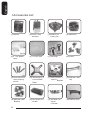
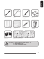
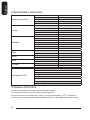
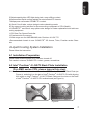
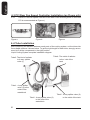
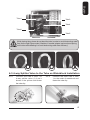
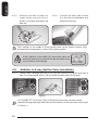
1
3D Galaxy II
GH-WIU02
English
User’s Manual
English
3D Galaxy II
Liquid Cooling System
Caution
1. Before pouring liquid coolant into the tank to test the liquid cooling system, please
reconfirm all the tubes have been fastened and the tube clips are in the right position.
2. While the water in the tank is lower than the low water-level, the red light on the bottom
of PCB will blink. (Please purchase GIGABYTE™ liquid coolant to fill it.)
3. When the liquid is lower than the low water-level, the system will turn off automatically
within four seconds after detection of water inadequacy.
4. While removing the tubes for disassembly, please make sure to keep all the devices
away from any electronic part. (Please refer to disassembly process instruction)
The following are not covered by the warranty
1.
2.
3.
4.
5.
6.
7.
8.
Use the product incorrectly or in a manner other than the designed purpose.
Nonobservance of the proper operation provided. (e.g. over-clocking)
Malfunction due to interference from other devices.
Unauthorized modification of the product.
Consequential damage to other objects due to the product’s fault.
Malfunction arising from casualties (earthquake, thunder, fire, and flood).
The product’s warranty label has been removed or damaged.
The devices inside, including power supply, hard disk, CD-ROM drive, motherboard,
ventilator, etc, are not detached from the casing prior to the transportation of the computer product, resulting in damage to the casing or computer-related devices.
9. Any loss caused by failure to follow the installation process contained in the user
manual.
10. Any damage to the system arising from coolant leakage due to improper installation.
11. Use only GIGABYTE™ Liquid Coolant. Any damage arising from the use of liquids
other than GIGABYTE™ Liquid Coolant is not covered by the warranty.
2
English
Table content
1 Accessories List
4
2 Specification Instruction
6
3 Feature Instruction
6
4 Liquid Cooling System Installation
7
4-1
Installation Preparation
®
®
7
4-2
Intel Pentium 4 LAG775 Back Plate Installation
7
4-3
PCI Rear Fan Speed Controller Installation
8
4-4
Tube Installation
8
4-5
4-way Splitter Valve to the Tube on Waterblock Installation
9
4-6
Radiator to 4-way Splitter Valve Installation
10
4-7
Radiator to the Inlet of Water Tank
11
4-8
4-way Splitter Valve to the Outlet of Water Pump
11
4-9
Waterblock Installation
12
4-10
Intel Pentium 4 LGA775 Bracket Installation
12
4-11
AMD K8 Clip Installation
13
4-12
AMD AM2 Clip Installation
13
4-13
Fasten 4-way Splitter Valve
14
4-14
MOSFET Air Cooling Fan Installation
14
4-15
Pump Power Cord Installation
15
4-16
Fan Speed Control Box and Power Cord Instruction
16
4-17
Fan Speed Control Box Installation
16
4-18
Heat Sink Installation
17
®
®
5 Liquid Cooling System Installation and Test
18
5-1
Liquid Cooling System Installation and Test
18
5-2
Radiator Installation
19
6 Liquid Cooling System Disassembly
20
7 4-way Splitter Valve Instruction and User Manual
22
3
English
1.Accessories List
(1) Radiator
(2) Pump + Tank
Assembly
(3) MOSFET Air
Cooling Fan
X2 pcs
(5) 4 - way Splitter
Valve
(4) Waterblock
X8 pcs
(6) 1 / 2 inch Tube
(7) Tube Clips
(8) Screws
X4
®
®
®
®
®
®
(9) Intel Pentium 4
LGA775 Spring
Screws
(10) Intel Pentium 4
LGA775 Back
(11) Intel Pentium 4
LGA775 Bracket
(12) AMD K8 / AM2
Clip
(13) AMD K8 / AM2
(14) Fan Speed Control Box
(15) PCI Rear Fan
Speed
Controller
(16) Radiator Rack
Bracket
4
Plate
English
X8 pcs
(17)Pump Power Cord
X2 pcs
(21)Bend Proof Spring
(18)Fan 1 to 2 Power
Cord
(19)Fan Speed
Control Power
Cord
(20)Heat Sink for
Memory
(23)Grease
(24)Gigabyte Liquid
Coolant
X4 pcs
(22)Nylon Tie
X2
(25)Velcro
(26)Quick Installtion Guide
No.8 Screw: a – Secure PCI Rear Fan Speed Controller ( 1pc )
b – Secure Radiator ( 3pcs )
c – Pump + Tank Assembly ( 2pcs )
5
English
2.Specification Instruction
Fan size
Fan speed
Fan Connector
Bearing
Noise
Dimensions
Maximum Capacity
Noise
Bearing
Life time
Dimensions
Material
Fan size
Fan speed
Fan Connector
Bearing
Noise
Dimensions
Capacity
Dimensions
Materia
Dimension
Material
Capacity
Color
Mosfet cooling fan
Pump
Radiator
Tank
Valve
Tube
Coolant
Compatible CPU
80 x 80 x 25 mm
2000 RPM
3 pin
EBR
19 dBA
61 x 60 x 46 mm
400 L/hr
20 dBA
Ceramic Bearing
70000 hr (MTBF)
125 x 197 x 64 mm
Aluminum
120 x 120 x 25 mm
1200 ~ 2600RPM
3 pin
2 Ball
19~39 dBA
100 x 53 x 172 mm
220cc.
inlet:1/2”; outlet:1/4”*2,1/2”*1
POM
1/2 inch
PVC, UV sensitive
600cc.
Lite Blue
Intel® Pentium® Extreme Edition Series
Intel® Pentium® D Processor Series
Intel® Pentium® 4 Processor Series (LGA775)
Intel® Core™ 2 Duo Processor Series
AMD AM2™ Series
AMD Athlon™ FX Series
AMD Athlon™ 64x2 Series
AMD Athlon™ 64 Series
3.Feature Instruction
1.Super huge copper base and unique water path design.
2.Long-lived, quiet and powerful ceramic bearing pump.
3.Auto-induction of low water-level ( LWP ) and over temperature ( OTP ) Protection.
4.Aluminum 4-way water path design radiator with 12 cm adjustable fan for lower noise.
6
English
5.Delicate sparkly blue LED light design tank; easy refilling coolant.
6.Well-executed liquid cooling radiator fits most existed PC chassis.
7.Multipurpose nanometer GIGABYTE™ coolant.
8.1/2inch UV soft tube; unique design to reduce bending needs.
9.Fully support cooling solution for the surrounding component of CPU (Mosfet).
10.GIGABYTE™ excusive 4-way splitter valve design for faster replacement and add new
cooling equipment.
11.PCI Rear Fan Speed Controller
12.Free heat sink for memory
13.Wide range use for AMD K8/AM2;Intel® Pentium® 4 LGA 775.
<Recommended chassis to use: GIGABYTE™ 3D Aurora, Triton, Poseidon series Chassis>
4.Liquid Cooling System Installation
Please follow the instruction.
4-1 Installation Preparation
Please make sure the power of PC has been turned off.
Tool needed: scissors, GIGABYTE™ coolant, grease, screwdriver.
®
®
4-2 Intel Pentium 4 LGA775 Back Plate Installation
(For AMD series CPU, please ignore this step)
4-2-1
®
®
Take off the double-side sticker on the Intel Pentium 4 LGA775 Back Plate (as
®
®
Figure a), and stick it on the back of Intel Pentium 4 LGA775 CPU with aligning
®
®
four holes on Intel Pentium 4 LGA775 Back Plate and four holes on the back
®
®
of Intel Pentium 4 LAG775 CPU motherboard (as Figure b).
Figure a
Figure b
7
English
4-3 PCI Rear Fan Speed Controller Installation (as Figure a/b)
4-3-1
Place PCI rear fan speed controller to the back of the chassis (place on the lower
PCI is recommended as Figure c.)
Figure a
Figure b
Figure c
4-4 Tube Installation
After measuring the distance between each parts of the cooling system, cut the tubes into
five suitable sizes as it shows below. To get the right length for each tube, strongly recommend to fit all the components in the right position.
Liquid Cooling System complete installation diagram.
Tube4: The outlet of radiator
to the inlet of the
tank
Tube3: The inlet of radiator
to 4-way splitter
valve (1)
B
A
Tube1: 4-way splitter
valve (1) to the
outlet of the
waterblock
B
A
Tube2 : 4-way splitter valve (2)
to the inlet of the
waterblock
8
Tube5 : 4-way splitter valve (2)
to the outlet of the tank
English
Tube1
Tube3
Tube4
Tube2
Tube5
While placing tube, please do not bend the tube in order to avoid obstructing water
flow (as the right Figure under). Besides, if needed, please use bend proof spring
on the tube while bending it to avoid obstructing water flow efficiency.
O
O
X
4-5 4-way Splitter Valve to the Tube on Waterblock Installation
4-5-1
Connect one side of tube 1 to
4-way splitter valve (1) A as it
shows in the picture and fasten
the tube clip.
4-5-2
Connect the other side of tube
1 to the outlet of waterblock and
fasten the tube clip.
9
English
4-5-3
Connect one side of tube 2 to
4-way splitter valve (2) B as it
shows in the figure and fasten the
tube clip.
4-5-4
Connect the other side of tube
2 to the inlet of waterblock and
fasten the tube clip.
The 2 splitters in the middle of 4-way splitter valve can be used to support VGA,
chipset liquid cooling system or other liquid cooling system.
If the 2 splitters in the middle of 4-way splitter valve are
available, please do not take off the cap and switch them
to horizontal to avoid leakage.
4-6
Radiator to 4-way Splitter Valve Installation
4-6-1
Thread Tube 3 through the hole on PCI slot (as Figure a) to connect one side of
tube 3 to 4-way splitter valve (1) B and fasten the tube clips (as Figure b).
Figure a
Figure b
Figure c
For GIGABYTE™ 3D Aurora, Triton or Poseidon series user, the tube can be
threaded through drainage inlet/outlet on the chassis.( as the two holes on the right
in Figure c )
10
English
4-6-2
Connect the other
side of tube 3 to the
inlet of radiator and
fasten the tube clips.
4-7 Radiator to the Inlet of Water Tank
4-7-1
Thread Tube 4
through the hole on
PCI slot to connect
one side of tube 4 to
the outlet of radiator
and fasten the tube
clips.
4-7-2
Connect the other side
of tube 4 to the inlet
of the tank and fasten
the tube clips.
4-8 4-way Splitter Valve to the Outlet of Water Pump
4-8-1
Connect one side of tube5 (as
Figure shown) to 4-way splitter
valve(2) and fasten the tube clips.
4-8-2
Connect the other side of tube5 to
the outlet of the pump and fasten
the tube clips.
11
English
4-9 Waterblock Installation
Please make sure to take off the“CAUTION”sticker and apply the grease on
the CPU surface evenly.
Note: AMD K8 Bracket can be removed from waterblock (as Figure a) to adjust
the appropriate installation direction. (as Figure b/c)
Figure a
Figure b
Figure c
4-10 Intel® Pentium® 4 LGA775 Bracket Installation
4-10-1
Figure a
12
®
®
Replace AMD K8 Bracket with Intel Pentium 4 LGA775 Bracket (accessory No.
®
®
11) ( Figure a ). Place the waterblock on the top of Intel Pentium 4 LGA775 CPU(
Figure b ) and adjust the appropriate installation direction ( Figure c ).
Figure b
Figure c
English
4-10-2
®
®
Secure Intel Pentium 4
LGA775 motherboard with
attached spring screws.
4-11 AMD K8 Clip Installation
4-11-1
Align the AMD K8 Clip to three
raised points on the CPU.
4-11-2
Push down the bar to surely
secure.
4-12-2
Push down the bar to surely
secure.
4-12 AMD AM2 Clip Installation
4-12-1
Align the AMD K8 clip to the
raised point on the CPU .
13
English
4-13 Fasten 4-way Splitter
Valve
4 -14 MOSFET Air Cooling
Fan Installation
4-13-1
Using the nylon tie to fasten
4-way splitter valve on trestle of
the chassis. If there is no trestle
available, try to find an applicable
place to fasten it.
4-14-1
Place MOSFET air cooling fan on
the top of waterblock and make
sure that four feet of the air cooling
fan are secured on waterblock.
4-14-2
Plug the power cord of MOSFET
air cooling fan to the socket on
motherboard CPU fan.
4-14-3
Plug the power cord of MOSFET
air cooling fan into fan 1 to 2
power cord.
a :3-pin CPU fan socket
b: 4-pin CPU fan socket (Intel® Pentium®
4 LGA775)
14
English
4-15 Pump Power Cord Installation
4-15-1
Prepare Pump Power Cord
a : 6-pin connector
b : female 2-pin connector
c : male 2-pin connector
d : 4-pin connector
A
C
D
4-15-2
Connect the Power SW (female
2- pin c onnec tor) f rom the
chassis’s panel with the pump
power cord male 2-pin connector.
a : Power SW (female 2- pin
connector) from the chassis’s
panel
b : Pump power cord male 2-pin
connector
4-15-3
Connect the pump power SW
cord female 2-pin connector
with “+ PW-“ jumper on the
motherboard.
4-15-4
Connect the pump
power cord 6-pin
connector with the back
of the tank, (as Figure a
/b)
Figure a
4-15-5
B
Figure b
Connect 4 -pin power supply
connector with the 4-pin pump
cord connector.
15
English
4-16 Fan Speed Control Box and Power Cord Instruction
PCI Rear Fan Speed
Control Box Connector
Power Cord
Fan Speed Control Box
Socket
Fan Speed Control Box
Radiator Fan Speed
Control Box Connector
Socket
Connect the other side
of power cord with fan 1
to 2 power cord
4-17 Fan Speed Control Box Installation
Tool needed: Fan Speed Control Box , Fan Speed Control Box Connect Line.
4-17-1
16
Thread the radiator fan connector
through the hole of PCI rear fan
speed controller.
4-17-2
Plug the connector from the PCI
rear fan speed controller into the
fan speed control box.
Plug the radiator fan power cord
into the fan speed control box.
4-17-4
To accomplish installation, plug the
power cord of fan speed control box
into the connector on the fan speed
control box (as Figure a) and plug the
other side of the power cord into the
available 1 to 2 socket (as Figure b).
Figure a
Figure b
4-18 Heat Sink Installation
4-18-1
Heat sink( 8 pcs) can be pasted on the small chips on the motherboard or VGA
card to lower the temperature.
17
English
4-17-3
English
5.Liquid Cooling System Installation and Test
Before pouring liquid coolant into the tank to test the liquid cooling system, please remove
the tank from the chassis to avoid damaging other components.
Before turning on the power, please confirm that all the tube clips are fastened; leakage of
liquid coolant due to improper installation may damage the system that is not covered by
warranty. (as figure showen)
Use only GIGABYTE™ liquid coolant; any damage arising from using
other liquid product is not covered by warranty.
5-1 Liquid Cooling System Installation and Test
Tool needed: Coolant
5-1-1
18
Open the lid of the tank to
pour in liquid coolant and
close the lid.
Turn on the power until all liquid coolant
drains into the tubes; the red light on the
bottom of the PCB will blink and bleep; the
system will turn off automatically within 4
seconds. (This is normal or initial refilling of
liquid coolant since the tube and radiator are
not full of liquid.)
5-1-3
Open the lid of the tank again to refill the tank
with liquid coolant and than close the lid. Turn
on the power one more time and repeat this
step until the water is no longer lower than
the low water-level.
English
5-1-2
Note: For the first time of pouring liquid coolant into the tank; the radiator should be
lay down flat to facilitate exhaust air to ensure the liquid cooling system to function
silently. Installing the radiator in accordance with the following step 5-2 ; make
sure all the air bubble in the tube has been removed to ensure the performance of
cooling.
Be aware of abnormal leakage. If the installation was correct and the tube
clips are fastened, and the liquid cooling system leaks, please turn off the
power immediately and drain out all coolant. Contact GIGABYTE™ dealers
or GIGABYTE™ service center.
5-2
Radiator Installation
5-2-1
Lock the radiator rack to the
radiator with screws.
5-2-2
Remove the 2 screws on the
p owe r s u p p l y at t h e r e a r of
chassis as shown.
19
English
5-2-3
To accomplish liquid cooling
system, align the 2 screw holes
on the radiator rack to the 2 screw
holes on the power supply and
fasten them up.
With GIGABYTE™ 3D Aurora,
Triton, Poseidon series, water tank
can be placed inside of the chassis.
[use 2 screws (b), please refer to
accessories list]
Velcro could be used to place the
tank while using the chassis other
than 3D Aurora, Triton and Poseidon
series.
6. Liquid Cooling System Disassembly
Tool needed: Pail, screwdriver
Preparation: Please place the chassis on a table and a pail on the floor.
While removing the tubes for disassembly, please make sure to keep all
the devices away from any electronic part.
6-1-1
20
Remove radiator from the rear
of the chassis and lay it on the
table.
(Caution: Do not remove the tube
at this point)
6-1-2
Remove MOSFET air cooling fan
from the waterblock.
English
6-1-3
Release the clip of waterblock
from CPU.
(Caution: Do not remove the tube
at this point)
6-1-4
Cut and remove the nylon tie
which is used to fasten 4-way
splitter valve.
6-1-5
Remove pump + tank and 4-way
splitter valve from the chassis;
and set a pail on a lower position
to fill the coming out coolant.
6-1-6
Release the tube clip on the inlet
of the waterblock; and place the
waterblock on the top of the pail.
6-1-7
Remove the tube; let the water
from waterblock and the tube drift
into the pail.
6-1-8
Release the tube clip on the inlet
of the tank and make sure if all the
coolant drifts out from the tube.
Remove the tube, tube clip and
spring.
21
English
6-1-9
Remove tube from PCI slot and
be careful to avoid the leakage.
Let the coolant drift into the pail.
For the tube on the other side of
radiator, please repeat this step
until all the coolant drifts out.
7. 4-way Splitter Valve Instruction and User Manual (Adding
VGA waterblock and chipset waterblock without disassembly)
Ex. GIGABYTE™ blue eye and chipset waterblock
7-1
Remove the caps and tube clips from
4-way splitter valve.
Do not switch on at this point.
7-2
Cut a tube into suitable size;
connect one side of the tube
with the first splitter on 4-way
splitter valve(1) and connect
the other side with the inlet of
VGA Blue Eye and fasten the
tube clips.
7-3
Cut a tube into suitable size;
connect one side of the tube
with the second splitter on
4-way splitter valve(2) and
connect the other side with the
outlet of VGA Blue Eye and
fasten the tube clips.
22
Please make sure to
turn off PC power
before installation.
Cut a tube into suitable
size; connect one side of
the tube with the second
splitter on 4-way splitter
valve(1) and connect the
other side with the outlet
of chipset waterblock and
fasten the tube clips.
7-5
Cut a tube into suitable
size; connect one side
of the tube with the first
splitter on 4-way splitter
valve(2) and connect the
other side with the inlet of
chipset waterblock and
fasten the tube clips.
7-6
Before turning on the
power, please make sure
all tube clips are fastened
(as shown on Figure a,
Figure b and Figure c)
and switch on the 4-way
splitter valve.
English
7-4
Figure a
Figure b
Figure c
Figure d
7-7 To accomplish liquid cooling system, after turning on the power, appropriately pour
coolant into the tank.
While removing the tubes for disassembly, please make sure to switch off
4-way splitter valve, turn off the power and keep all the devices away from
any electronic part.
23
24
English