1
No. CP-SP-1027E
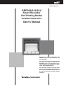
SRF206/212/224
Smart Recorder
Dot Printing Model
"Installation/Operation"
User's Manual
Thank you for purchasing the
SRF206/212/224 Smart Recorder Dot
Printing Model.
This manual contains information for
ensuring the correct use of the
SRF206/212/224. It also provides necessary information for installation, maintenance, and troubleshooting.
This manual should be read by those
who design and maintain equipment
that uses the SRF206/212/224. Be sure
to keep this manual nearby for handy
reference.
RESTRICTIONS ON USE
This product has been designed, developed and manufactured for general-purpose
application in machinery and equipment.
Accordingly, when used in applications outlined below, special care should be taken to
implement a fail-safe and/or redundant design concept as well as a periodic
maintenance program.
• Safety devices for plant worker protection
• Start/stop control devices for transportation and material handling machines
• Aeronautical/aerospace machines
• Control devices for nuclear reactors
Never use this product in applications where human safety may be put at risk.
NOTICE
Be sure that the user receives this manual before the product is used.
Copying or duplicating this user’s manual in part or in whole is forbidden. The information and specifications in this manual are subject to
change without notice.
Considerable effort has been made to ensure that this manual is free
from inaccuracies and omissions. If you should find an error or omission, please contact Yamatake Corporation.
In no event is Yamatake Corporation liable to anyone for any indirect,
special or consequential damages as a result of using this product.
©1998 Yamatake Corporation ALL RIGHTS RESERVED
TM
The SRF is a trademark of Yamatake Corporation in Japan.
SAFETY REQUIREMENT
To reduce risk of electrical shock which could cause personal injury,
follow all safety notices in this documentation.
This symbol warns the user of a potential shock hazard where
hazardous live voltages may be accessible.
• If the equipment is used in a manner not specified by the manufacturer, the protection provided by the
equipment must be impaired.
• Do not replace any component (or part) not explicitly specified as replaceable by your supplier.
• All wiring must be in accordance with local norms and carried out by authorized experienced personnel.
• The protective terminal earth must be connected before any other wiring (and disconnected last).
(Class I:IEC536)
EQUIPMENT RATINGS
Supply voltages:
Frequency:
Power or current ratings:
Fuse:
Sound pressure level:
100 to 240Vac (allowable voltage: 90 to 250Vac)
50/60Hz
100VA maximum
3A 250V, Time-lag (IEC127)
80dB(A) maximum (at a position of 1 meter from the equipment)
EQUIPMENT CONDITIONS
Do not operate the instrument in the presence of flammable liquids or vapors. Operation of any electrical
instrument in such an environment constitutes a safety hazard.
Temperature:
0 to 50°C
Humidity:
30 to 90%RH
Vibration:
Frequency 0 to 100Hz
Acceleration 0.98m/s2 maximum
Over-voltage category:
CategoryII (IEC60364-4-443, IEC60664-1)
Pollution degree:
Pollution degree 2
Environmental condition:
Permanently connected equipment, Indoor use, Panel mounted equipment
EQUIPMENT INSTALLATION
The recorder must be mounted into a panel to limit operator access to the rear terminals.
Specification of common mode voltage: The common mode voltages of all I/O except for main supply and relay
outputs are less than 33Vrms, 46.7V peak and 70Vdc.
APPLICABLE STANDARDS
EN61010-1, EN61326
Handling Precautions
When the carring handle kit is installed, the recorder does not conform to the standard
EN61010-1.
CAUTION
Danger of explosion if battery is incorrectly replaced.
Replace only with the same or equivalent type recommended by the manufacturer.
Dispose of used batterries according to the manufacturer’s instructions.
i
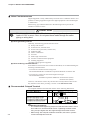
SAFETY PRECAUTIONS
■ About Icons
The safety precautions described in this manual are indicated by various icons.
Please be sure you read and understand the icons and their meanings described
below before reading the rest of the manual.
Safety precautions are intended to ensure the safe and correct use of this product, to prevent injury to the operator and others, and to prevent damage to property. Be sure to observe these safety precautions.
WARNING
Warnings are indicated when mishandling this
product might result in death or serious injury.
CAUTION
Cautions are indicated when mishandling this
product might result in minor injury to the user, or
only physical damage to the product.
■ Examples
Use caution when handling the product.
The indicated action is prohibited.
Be sure to follow the indicated instructions.
ii
WARNING
Before removing/mounting or wiring the SRF206/212/224, be sure to
turn the power OFF.
Touching electrically charged parts on the SRF206/212/224 such as
terminals by mistake might cause electric shock.
Before connecting the SRF206/212/224 to the measurement target or
external control circuits, make sure that a protective ground terminal is
connected to the SRF206/212/224.
Failure to do so might cause electric shock or fire.
The black-headed screw on the right of the main unit is for ground
protection. Never remove this screw.
Doing so might cause electric shock.
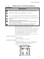
To prevent danger before you replace the clock backup battery, turn the
power OFF, and disconnect the SRF206/212/224 from its power supply.
CAUTION
Wire the SRF206/212/224 according to established standards. Also wire
the SRF206/212/224 using designated power leads according to
recognized installation methods.
Failure to do might cause electric shock, fire or faulty operation.
Use the SRF206/212/224 within the operating ranges recommended in
the specifications (temperature, humidity, voltage, vibration, shock,
atmosphere, etc.). Failure to do so might cause faulty operation.
Do not block ventilation holes.
Doing so might cause faulty operation.
Do not disassemble the SRF206/212/224, nor touch components inside
the SRF206/212/224.
Doing so might cause electric shock or faulty operation.
Load the chart and ink ribbon cassette either with the power OFF or
with the recorder stopped (the RCD LED should be OFF). Do not push
the cassette with excessive force. Doing so might force a movement of
the ink ribbon cassette holder (see page 4-4), damaging the gear and
causing faulty operation.
Do not touch internal components during use or immediately after
turning the power OFF.
Doing so might cause burns.
Do not touch moving parts during operation.
Doing so might cause injury.
Do not operate the keys with a mechanical pencil or other sharp-tipped
object.
Doing so might cause faulty operation.
iii
Unpacking
■ Check the model No.
Check the model No. to make sure that you have received the product that you
ordered. The model No. for this product is listed at two places: on the side of the
case and on the inner left side of the chassis.
See ■ Overall Schematic and Names of Parts (page2-1).
For details on whether this product supports optional functions and optional
specifications, see 1-2 Model Selection Guide (page 1-3).
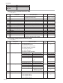
■ Check the package for the following items
Name
Model No.
Recorder
Q’ty
1
Folding chart 100-sections
81407861-001
1
Ink ribbon cassette
81407408-001
1
Fuse
81446289-002
1
Mounting bracket
81446291-002
1
Installation/operation
CP-SP-1027E
1
SRF206/212/224
CPL communications
CP-SP-1028E
1
User's manual
Remarks
See 1-2 Model Selection Guide,
page 1-3.
This manual
■ A note about shipping
Transportation fastening screws are not used as the structure of this product is such
that the chassis (inner part of the recorder) is fastened to the case by screws.
■ Do not remove the black-headed screw on the recorder
WARNING
The black-headed screw on the right of the main unit is for ground protection.
Never remove this screw.
Doing so might cause electric shock.
iv
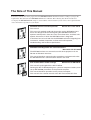
The Role of This Manual
In all, three manuals have been prepared for the SRF206/212/224. Read the manual according to your specific
requirements. This manual is the SRF206/212/224 User’s Manual. The following lists all the manuals that
accompany the SRF206/212/224 and gives a brief outline of the manual. If you do not have the required manual,
contact Yamatake Corporation or your dealer.
SRF206/212/224 Installation/Operation
Manual No. CP-SP-1027E
This manual.
This manual is required reading for those who use the SRF206/212/224,
those who design hardware for integrating the SRF206/212/224 into
operator control panels, those who carry out maintenance, and those who
operate instruments in which the SRF206/212/224 is integrated.
It describes how to install and wire the SRF206/212/224 for integrating into
instruments, method of operation, maintenance and inspection,
troubleshooting, and hardware specifications.
SRF206/212/224 DigitroniK CPL Communications
Manual No. CP-SP-1028E
The SRF206/212/224 can communicate with other equipment via the
RS-485 or RS-232C interfaces.
This manual describes communications procedures and commands when
the SRF206/212/224’s communications features are used.
SLP-F10/F20 Smart Loader Package
Manual No. CP-UM-5067E
This manual is packaged with the SLP-F10/F20.
Running the SLP-F10/F20 package on a personal computer enables you to
set up SRF100/200 parameters on the personal computer.
This manual describes operations on the personal computer.
This manual is the common manual of the SLP-F10 and the SLP-F20.
v
Organization of This User’s Manual
This manual is organized as follows:
Chapter 1. INTRODUCTION
This chapter describes SRF206/212/224 applications and features, and gives a
list of catalog numbers.
Chapter 2. NAMES AND FUNCTIONS OF PARTS
This chapter describes the names and functions of parts of the SRF206/212/224.
Chapter 3. INSTALLATION AND WIRING
This chapter describes precautions, siting conditions and installation method when
installing the SRF206/212/224 into devices, and how to connect to peripheral
equipment.
Chapter 4. PREPARATION AND OPERATION
This chapter describes checks to carry out before operating the SRF206/212/224
and daily operation procedure.
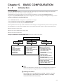
Chapter 5. BASIC CONFIGURATION
This chapter describes the basic setup details of the SRF206/212/224.
Chapter 6. DETAILED CONFIGURATION
This chapter describes all items that can be set using the operation keys.
Chapter 7. MAINTENANCE
This chapter describes inspection items and how to replace maintenance parts to
ensure prolonged use of the SRF206/212/224.
Chapter 8. TROUBLESHOOTING
This chapter describes points to check when the SRF206/212/224 is not working
properly and how to remedy trouble that might occur.
Chapter 9. SPECIFICATIONS
This chapter describes the general specifications, performance specifications and
external dimensions of the SRF206/212/224.
APPENDICES
vi
Contents
SAFETY REQUIREMENT
SAFETY PRECAUTIONS
Unpacking
The Role of This Manual
Organization of This User’s Manual
Conventions Used in This Manual
Chapter 1.
INTRODUCTION
1-1 Applications and Features ................................................................................1-1
■ Features........................................................................................................1-1
■ Optional Functions ......................................................................................1-2
1-2 Model Selection Guide ......................................................................................1-3
■ Model Listing................................................................................................1-3
■ Related Parts Model Listing........................................................................1-3
Chapter 2.
NAMES AND FUNCTIONS OF PARTS
2-1 Main Unit.............................................................................................................2-1
■ Overall Schematic and Names of Parts .....................................................2-1
■ Terminals on Rear Side...............................................................................2-2
2-2 Display Setup Unit .............................................................................................2-3
■ Operation Display and Operation Keys .....................................................2-3
■ Configuration Unit and Operation Keys ....................................................2-4
Chapter 3.
INSTALLATION AND WIRING
3-1 Installation Site ..................................................................................................3-1
■ Siting Conditions .........................................................................................3-1
3-2 Installation ..........................................................................................................3-2
■ Installation Dimensions ..............................................................................3-2
■ Installation Procedure .................................................................................3-2
3-3 Wiring Precautions ............................................................................................3-3
■ Description of Symbols on Terminal Layout Label ..................................3-3
■ Noise Countermeasures .............................................................................3-4
■ Recommended Crimped Terminal .............................................................3-4
3-4 Connecting the Power Supply and Ground.....................................................3-5
3-5 I/O Signal Leads .................................................................................................3-6
■ Wiring Analog Inputs...................................................................................3-7
■ Wiring Relay Outputs (optional function)..................................................3-8
■ Wiring Open Collector Outputs (optional function) .................................3-9
■ Wiring External Switch Inputs (optional function) .................................3-11
■ Connecting the RS-485 Interface (optional function).............................3-12
■ Connecting the RS-232C Interface (optional function) ..........................3-13
vii
Chapter 4.
PREPARATION AND OPERATION
4-1 Preparation (loading the chart and ink ribbon cassette) ...............................4-1
■ Loading the Chart ........................................................................................4-1
■ Loading the Ink Ribbon Cassette...............................................................4-4
4-2 Operation ............................................................................................................4-6
■ Turning the Power ON.................................................................................4-6
■ Starting/stopping Recording ......................................................................4-6
■ Feeding the Chart ........................................................................................4-7
■ Selecting the Display Mode ........................................................................4-7
■ Recording a Specific Table.........................................................................4-8
■ Other Displays and Operations ..................................................................4-9
■ Printout Details ............................................................................................4-9
■ Replacing the Chart...................................................................................4-12
■ Replacing the Ink Ribbon Cassette..........................................................4-13
Chapter 5.
BASIC CONFIGURATION
5-1 Introduction ........................................................................................................5-1
5-2 Basic Key Operations at Setup, Configuration Lock and Menu Levels........5-2
■ Basic Key Operations at Setup ..................................................................5-2
■ Canceling Configuration Lock....................................................................5-4
■ Changing the Menu Level ...........................................................................5-5
5-3 Changing Event Setting Values........................................................................5-6
■ Starting Setup ..............................................................................................5-6
■ Selecting the Target Channel No. ..............................................................5-6
■ Selecting the Target Event No....................................................................5-7
■ Enabling Changing of Event Setting Values .............................................5-7
■ Entering Event Setting Values....................................................................5-7
5-4 Changing the Date/Time....................................................................................5-8
■ Starting Setup ..............................................................................................5-8
■ Changing the Date .......................................................................................5-8
■ Changing the Time ......................................................................................5-8
5-5 Printing Lists ......................................................................................................5-9
■ Stopping Recording ....................................................................................5-9
■ Starting Setup ..............................................................................................5-9
■ Selecting the List to be Printed ................................................................5-10
■ Stopping List Printing Midway .................................................................5-10
■ Print Communications List .......................................................................5-10
■ Print Specified Lists ..................................................................................5-11
■ Print All Lists..............................................................................................5-13
viii
Chapter 6.
DETAILED CONFIGURATION
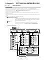
6-1 Introduction ........................................................................................................6-1
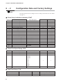
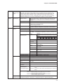
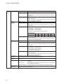
6-2 Configuration Data and Factory Settings ........................................................6-2
■ Event Setup (individual channels): EVNT .................................................6-2
■ Chart Feed Speed Setup: SPD....................................................................6-2
■ Date/Time Setup: CLK .................................................................................6-2
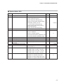
■ System Setup: SYS......................................................................................6-3
■ Range Setup (individual channels): RNG..................................................6-4
■ Calculation Setup (individual channels): RNG .........................................6-4
■ Scale Setup (individual channels): SCL ....................................................6-5
■ Copy Function: COPY .................................................................................6-5
■ Schedule Demand: SYS + S d. ..................................................................6-5
■ Message Setup: SYS + n.S. .......................................................................6-6
■ User Function Key Setup: SYS + U 1./ U 2. ...............................................6-7
■ Extended Setup: SYS + E T. ......................................................................6-8
■ External Switch Input Setup: ST + E S./
Internal Contact Input Setup: ST + I S. ....................................................6-9
■ Relay Output Setup: SYS + R O./
Open Collector Output Setup: SYS + D O. ...............................................6-9
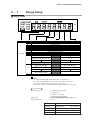
■ Segment Table 1 Setup: SYS + T A., T B. ................................................6-10
■ Segment Table 2 Setup: SYS + T C., T D. ................................................6-10
■ Segment Table 3 Setup: SYS + T E., T F. ................................................6-10
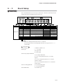
6-3 Event Setup ......................................................................................................6-11
■ Event Setup ................................................................................................6-11
■ Description of Event Setup Items ............................................................6-12
6-4 Chart Feed Speed Setup .................................................................................6-13
■ Chart Feed Speed Setup ...........................................................................6-13
■ Description of Chart Feed Speed Setup Items........................................6-14
6-5 Date/Time Setup...............................................................................................6-15
■ Date/Time Setup.........................................................................................6-15
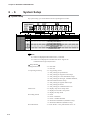
6-6 System Setup ...................................................................................................6-16
■ System Setup .............................................................................................6-16
■ Description of System Setup Items .........................................................6-18
6-7 Range Setup .....................................................................................................6-19
■ Range Setup...............................................................................................6-19
■ How to Set the Engineering Unit ..............................................................6-20
■ Description of Range Setup Items ...........................................................6-20
6-8 Calculation Setup.............................................................................................6-23
■ Calculation Setup ......................................................................................6-23
■ Description of Calculation Setups ...........................................................6-24
6-9 Scale Setup ......................................................................................................6-26
■ Scale Setup ................................................................................................6-26
■ Description of Scale Setup Items.............................................................6-27
6-10 Copy Function..................................................................................................6-29
■ Copy Function............................................................................................6-29
6-11 Schedule Demand Setup.................................................................................6-30
■ Schedule Demand Setup...........................................................................6-30
■ Description of Schedule Demand Setup .................................................6-31
ix
6-12 Message Setup.................................................................................................6-32
■ Message Setup...........................................................................................6-32
6-13 User Function Key Setup ................................................................................6-33
■ Setting Configuration Lock.......................................................................6-33
■ Description of User Function Key Setup.................................................6-34
6-14 Extended Setup................................................................................................6-35
■ Extended Setup..........................................................................................6-35
■ Description of Extended Setup ................................................................6-35
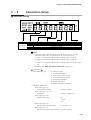
6-15 External Switch Input/Internal Contact Input Setup .....................................6-37
■ External Switch Input Setup .....................................................................6-37
■ Internal Contact Input Setup.....................................................................6-37
■ Description of External Switch Input/Internal Contact Input Setup......6-39
6-16 Relay Output Setup..........................................................................................6-40
■ Relay Output Setup ...................................................................................6-40
■ Description of Relay Output Setup ..........................................................6-41
6-17 Open Collector Output Setup .........................................................................6-43
■ Open Collector Output Setup ...................................................................6-43
6-18 Segment Table Setup ......................................................................................6-44
■ Segment Table Setup ................................................................................6-44
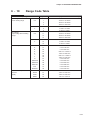
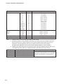
6-19 Range Code Table............................................................................................6-47
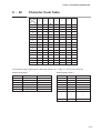
6-20 Character Code Table......................................................................................6-49
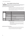
6-21 About Digital Printing Priority ........................................................................6-50
■ Printing Control During a Print Conflict ..................................................6-50
■ Simultaneous Printing Control.................................................................6-50
6-22 Calculation Functions .....................................................................................6-51
■ Broken-line approximation .......................................................................6-52
■ Input Calculation........................................................................................6-53
6-23 Operation of External Switch Input/Internal Contact Input Functions........6-56
Chapter 7.
MAINTENANCE
7-1
7-2
7-3
7-4
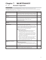
Periodic Inspection............................................................................................7-1
Replacing the Clock Backup Battery ...............................................................7-3
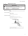
Replacing the Fuse ............................................................................................7-5
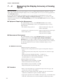
Measuring the Display Accuracy of Analog Inputs ........................................7-6
■ Equipment Required for Measurement......................................................7-6
■ Measurement Environment.........................................................................7-6
■ Procedure .....................................................................................................7-6
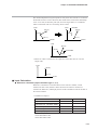
7-5 Adjusting the Dot Position................................................................................7-8
■ About Recording Accuracy ........................................................................7-8
■ About Standard Conditions ........................................................................7-8
■ Procedure .....................................................................................................7-9
Chapter 8.
TROUBLESHOOTING
8-1 Alarm Display and Descriptions.......................................................................8-1
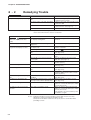
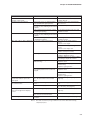
8-2 Remedying Trouble ...........................................................................................8-4
Chapter 9.
SPECIFICATIONS
x
Chapter 9.
SPECIFICATIONS
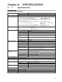
9-1 Specifications ....................................................................................................9-1
■ General Specifications ................................................................................9-1
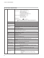
■ Performance Specifications .......................................................................9-2
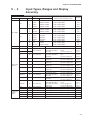
9-2 Input Types, Ranges and Display Accuracy ...................................................9-7
9-3 External Dimensions .........................................................................................9-9
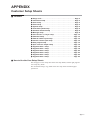
APPENDICES
Customer Setup Sheets
■ Contents .................................................................................................App.-1
■ How to Use the User Setup Sheets ......................................................App.-1
Conventions Used in This Manual
The following conventions are used in this manual:
Handling Precautions
: Handling Precautions indicate items that the user should pay attention
to when handling the SRF206/212/224.
Note
AL03
DMD
ENT
key
key
(1)(2)(3)
: Notes indicate useful information that the user might benefit by
knowing.
: These indicate 7-segment indications on the data display.
: These icons represent keys on the SRF206/212/224.
: The numbers with the parenthesis indicate steps in a sequence or
indicate corresponding parts in an explanation.
xi
Chapter 1.
1 - 1
INTRODUCTION
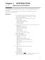
Applications and Features
This multi-input, 6/12/24 dot printing, high-function recorder accommodates a 180mm wide chart. This recorder
offers the dual features of advanced functions and operating ease as a recorder for various equipment and
instrumentation.
It also supports relay output, open collector output, external switch inputs, chart illumination lamp and
communications, as optional functions.
■ Features
●
Any combination of inputs and recording scales can be freely set.
DC voltage, thermocouple, resistance temperature detector (RTD),
communications, ON/OFF input
●
Five recording formats are provided and can be freely selected:
• Trend recording
• Trend + tabulation recording
• Trend + schedule demand recording
• Fixed interval tabulation
• Fixed time tabulation
●
Six measurement and calculation methods are provided and can be selected to
each channel:
• Measurement value (PV value)
• Deviation value between channels
• Deviation value from fixed value
• Total calculation
• F value calculation
• Temperature/humidity calculation
●
Universed power supply allows use anywhere:
100 to 240Vdc, 50/60Hz
●
Wide range of printing functions:
• Measurement value (PV value)
• Channel No.
• Tag (12 characters per channel)
• Engineering unit (6 characters per channel)
• Recording scale (2 types, upper/lower limit values)
• Chart feed speed
• Event status (details, time of occurrence/restoration)
• Time marker
• Date
• Time (h:min)
●
Printing at the following start conditions is possible:
• Date
• Time (h:min)
• Recording format
• Chart feed speed
• Recorder ID No.
●
Demand printing also is possible.
DMD
Printing is started by the
key or external switch input (option), and time
(h:min) and measurement values (PV value) are printed.
1-1
Chapter 1. INTRODUCTION
●
When trend + schedule demand recording is selected as the recording format,
the measurement value (PV value) of up to eight preset times can automatically
be printed.
●
Up to 24 digital inputs are supported: 12 external switch inputs coupled to
remote switches, and 12 internal contact inputs that are connected to internal
signals.
Output signals for up to 96 events (4 types x 24 channels) can be connected to
any 12 internal contact inputs.
●
Parameter setups can be assigned to user function keys, (up to eight types for
each of the two switches).
●
Printing of “Date/Time (h:min)”, “Scale” and “event” can be disabled.
●
Seven list printing modes are available for printing setup data: print specified
list, print function lists (four modes), print all lists and print user lists.
●
Upscale, downscale or OFF can be set as the thermocouple burnout setting for
each input channel.
●
Setup data is protected in EEPROM when the power is OFF.
●
Copy setting
Various setup data can be copied between channels.
●
Segment table setup
Output values (Y-axis) for input values (X-axis) can be offset by setting up
segment tables.
●
Print user setup lists
Any list (85 characters x 3 lines) can be printed from a loader or by CPL
communications.
■ Optional Functions
The following optional functions are available:
1-2
●
Relay outputs
(6/12 outputs; SPDT relay output)
●
External switch inputs
●
Open collector outputs
(4/8/12; Recording ON/OFF, Demand printing,
Chart feed, Print messages No.1 to No.8, Chart
feed speed/Scale selection, etc.)
(12 outputs)
●
Chart illumination lamp
(cold cathode fluorescent light)
●
Communications
(RS-485, RS-232C)
Chapter 1. INTRODUCTION
1 - 2
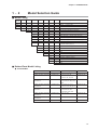
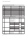
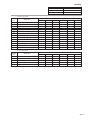
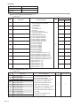
Model Selection Guide
■ Model Listing
Basic
model No.
Power
Input
Option 1
Option 2
Option 3 Addition 1 Addition 2
Specifications
SRF206
180mm
6-dot recorder
SRF212
180mm
12-dot recorder
SRF224
180mm
24-dot recorder
A
100 to 240Vac, 50/60Hz
S
Full multi-input (standard specification)
0
None
1
Relay outputs (6)
2
Relay outputs (6) + external switch inputs (4)
4
Relay outputs (12)
5
Relay outputs (12) + external switch inputs (8)
7
Relay outputs (12) + open collector outputs (12)
8
Relay outputs (12) + open collector outputs (12)
+ external switch inputs (12)
0
Communications not supported
1
RS-485
2
RS-232C
0
None
1
Chart illumination lamp provided
0
None
D
Inspection certificate provided
T
Tropical treatment
B
Tropical treatment + Inspection certificate provided
0
None
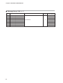
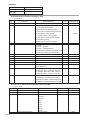
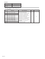
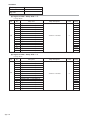
■ Related Parts Model Listing
● Consumables
Name
Model No.
Application Range (example)
Remarks
Folding chart 100-sections
Folding chart (Recycled paper)
100-sections
81407861-001
81409978-001
0, 20, 40, 60, 80, 100
0, 10, 20, 30, 40, 50
0, 20, 40, 60, 80, 100
0, 40, 80, 120, 160, 200
10 packets, 20m
10 packets, 20m
Folding chart (Recycled paper)
120-sections
81409978-002
0, 10, 20, 30, 40, 50, 60
0, 200, 400, 600, 800, 1000,
1200
10 packets, 20m
Folding chart (Recycled paper)
140-sections
81409978-003
0, 2, 4, 6, 8, 10, 12, 14
0, 10, 20, 30, 40, 50, 60, 70
10 packets, 20m
Folding chart (Recycled paper)
80-sections
81409978-004
0, 20, 40, 60, 80
0, 100, 200, 300, 400
0, 400, 800, 1200, 1600
10 packets, 20m
Folding chart (Recycled paper)
150-sections
81409978-005
0, 50, 100, 150
10 packets, 20m
Clean paper chart
100-sections
81407937-001
0, 20, 40, 60, 80, 100
10 packets, 16m
Ink ribbon cassette
81407408-001
—
1 cassette
1-3
Chapter 1. INTRODUCTION
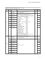
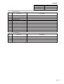
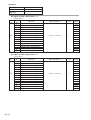
● Optional parts
Name
Model No.
Remarks
250Ω resistor (accuracy ±0.02%)
81401325
1 p’ce
250Ω resistor (accuracy ±0.05%)
81446642-001
2 p’ces
Cross cable for RS-232C interface
Carrying handle kit
CBL232FNZ02
81446643-001
1 p’ce , 2m
With power cable supplied
Add-on optional unit
81446645-001
6 relays
Add-on optional unit
81446645-002
6 relays + RSW (4)
Add-on optional unit
81446645-003
6 relays + RSW (4) + RS-232C
Add-on optional unit
81446645-004
6 relays + RSW (4) + RS-485
Add-on optional unit
81446645-007
RS-232C
Add-on optional unit
81446645-011
12 open collectors + RSW (4)
RSW: External switch input
● Maintenance parts
Name
Model No.
Remarks
Standard tag plate
81446612-001
Fuse
81446289-002
10 p’ces
Mounting bracket
81446291-002
1 set (2 brackets)
Replacement door
81446608-001
With pin and spring
Chart cassette
81446609-001
Unit ass’y component
Chart holder
81446610-001
Plastic formed component
Chart guide
81446611-001
Plastic formed component
(transparent)
Chart holding sheet
81446613-001
5 p’ces
Option terminal cover
81446427-002
Analog input terminal cover
81446428-002
Power terminal cover
81446429-001
M3.5 free terminal screw
81446441-002
Power cable
81446475-001
10 p’ces
10 p’ces
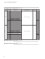
● Smart Loader Package SLP
Name
Smart Loader Package
1-4
Model No.
SLP-F20
Remarks
Chapter 2.
2 - 1
NAMES AND FUNCTIONS OF PARTS
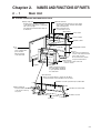
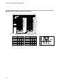
Main Unit
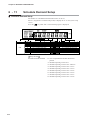
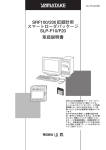
■ Overall Schematic and Names of Parts
Optional terminals:
Contains optional terminals for relay output,
open collector output, external switch input
and communications.
Display setup unit:
Comprises the operation controller
on the bottom right and the configuration
unit on the top right.
The optional chart illumination lamp can
be fixed here.
Loader connection jack:
Located under console
Wiring labels
Power switch
Case
Power terminal
Model No. labels
Analog input terminal
Door:
This left-hinged door
forms a simple dustproof structure
with the packing
on the main unit.
Chassis:
This chassis is fixed by four
screws on the innermost side
of the chart cassette.
Do not remove the chassis
except for maintenance.
Chart cassette:
This cassette can be removed
from the chassis.
Tag plate
Chart guide:
Made of transparent plastic,
the chart guide is designed
to open upwards and holds
the chart down.
Wire dot head:
Wires are magnet-driven to punch the ink ribbon
to transfer the ink on the ink ribbon onto the chart.
Ink ribbon cassette replacement procedure label
Ribbon feed knob:
Turn this knob in the direction
of the arrow to take up
any slack.
Ink ribbon cassette holder
Ink ribbon cassette
Ink ribbon
2-1
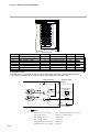
Chapter 2. NAMES AND FUNCTIONS OF PARTS
■ Terminals on Rear Side
Power terminals
Option terminals
Analog input terminals
For details on signals connected to terminals, see Chapter 3. INSTALLATION
& WIRING.
2-2
Chapter 2. NAMES AND FUNCTIONS OF PARTS
2 - 2
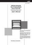
Display Setup Unit
■ Operation Display and Operation Keys
The following describes the operation panel on the display setup unit:
● Operation keys
LOCK
EVNT
CLK
RNG
CH
COPY
SPD
SYS
SCL
UF1
EVNT
SET
DATA
C
UF2
ACK
ENT
AUTO MAN
FEED
DMD
RCD
CLK
DISP
Display key:
Return from setup/display select
Record key: Starts/stops recording.
Demand key: Starts demand printing.
Feed key: Feeds chart for the duration that this key is
held down.
● Operation display
Lights when channel-related data is displayed.
Lights when an event occurs.
LOCK
EVNT
CLK
RNG
CH
COPY
SPD
SYS
SCL
UF1
EVNT
Temperature unit
SET
DATA
˚C
UF2
ACK
ENT
AUTO MAN
FEED
DMD
RCD
Fixed channel display
(Select channel by and
CLK
keys.)
DISP
Date/time display
Automatic channel selection
(4 secs/channel)
Lights during recording
Data display
(Eight 7-segment LEDs are used.
The 3rd LED from left facing the front
is red. Others are green.)
Lights during demand printing
Red LED
Display examples
AUTO or MAN indicates PV input value.
The example on the left shows a value of 18.0 for channel 1.
CLK indicates the date.
The example on the left shows the date June (06) 24th (24) 1997 (97) .
CLK indicates the time.
The example on the left shows the time 13:28 .
2-3
Chapter 2. NAMES AND FUNCTIONS OF PARTS
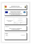
■ Configuration Unit and Operation Keys
The following describes the configuration unit on the display setup unit:
● Setup keys
Up/down keys: Changes (increments/decrements)
numerical values, and
shifts the menu number.
LOCK
EVNT
CLK
RNG
CH
COPY
SPD
SYS
SCL
UF1
EVNT
SET
DATA
C
AUTO MAN
ACK
UF2
ENT
FEED
DMD
RCD
CLK
Set key: Enters the setup mode,
and selects setup items.
Enter key: Shifts the menu number,
and fixes numerical values.
DISP
Shift key: Shifts the digit (cursor)
to the left and right.
● Setup display
LOCK
EVNT
CLK
RNG
CH
COPY
SPD
SYS
SCL
SET
DATA
C
UF2
UF1
EVNT
ACK
ENT
AUTO MAN
FEED
DMD
RCD
CLK
DISP
LOCK : The configuration is locked. (When lit, setups can be confirmed but not changed. Setups can be
changed by the user configuration keys.)
EVNT : Event setting is being set up. (Event type and differentials can also be set according to the
system setup level.)
SPD
: Chart feed speed is being set up. (Sets the chart feed speed.)
CLK
: Date and time (h:min) are being set up.
SYS
: The system is being set up. (Menu levels for locking configuration, printing lists and entering
more detailed menus can be set.)
RNG : The input range is being set up. (The recording mode, input type, measurement range and PV
bias can be set according to the menu level.)
SCL
: Scale is being set up. (The recording scale can be set according to the menu level.)
COPY : Copy is being set up. (Setups can be copied to other channels.)
Display examples
SYS
Checking or setting events:
In the example on the left,
the setting of event setup 1 on channel 1 is 50.0.
EVNT
SPD
2-4
Checking or setting configuration lock:
In the example on the left,
the configuration lock setting is 1.
Checking or setting the chart feed speed:
In the example on the left,
the chart feed speed 1 setting is 40mm/h.
Chapter 2. NAMES AND FUNCTIONS OF PARTS
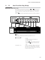
● Operation keys
LOCK
EVNT
CLK
RNG
CH
COPY
SPD
SYS
SCL
UF1
EVNT
SET
DATA
C
UF2
ACK
ENT
AUTO MAN
FEED
DMD
RCD
CLK
DISP
Hold output cancel key:
Cancels enabling of relay output and open collector output hold.
User function keys:
Calls up preset setup items.
Can also be used for internal contact inputs.
2-5
Chapter 3.
3 - 1
INSTALLATION AND WIRING
Installation Site
■ Siting Conditions
The SRF206/212/224 is for indoor installation only. Install the
SRF206/212/224 at a location that satisfies the following conditions:
(1) Close to room temperature, not subject to large changes in temperature
(2) Not exposed to corrosive gas
(3) Humidity is neither excessively low or high
(4) Not subject to excessive mechanical vibration
(5) Not subject to excessive dust or oil smoke
(6) Not subject to excessive electrical noise
(7) Not subject to magnetic fields
Handling Precautions
• Keep the mounting angle to within 0 to 30° from the bottom rear (bottom
rear angle) or to within 0 to 3° from the top rear (top rear angle).
• Use a panel of at least 2mm in thickness for mounting the
SRF206/212/224.
● Mounting with back angled down
Panel thickness 2 to 25mm
Panel
Door
。
Max. 30 downward angle
from horizontal position
● Mounting with back angled up
Panel thickness 2 to 25mm
Panel
。
Max. 3 upward angle
from horizontal position
Door
3-1
Chapter 3. INSTALLATION AND WIRING
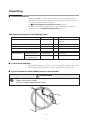
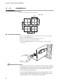
3 - 2
Installation
■ Installation Dimensions
The panel cutout dimensions are as follows:
(Unit: mm)
340 min.
281
+2
0
+2
281 0
340 min.
■ Installation Procedure
Use one of the mounting holes at the top, bottom, left or right of the case when
mounting the SRF206/212/224.
(1) Remove the seal covering the mounting hole to be used.
(2) Insert the main unit case from the panel front.
(3) Install the SRF206/212/224 onto the panel using the mounting brackets
(provided).
Handling Precautions
• Remove the seal from only the mounting hole to be used when installing
the SRF206/212/224. Do not remove the seals from the other mounting
holes where the mounting bracket is not to be installed. These seals
prevent dust from entering the case.
• The recommended tightening torque for the mounting bracket is 1.0 to
1.5N•m. Tightening the mounting bracket with a torque higher than this
might deform the case or damage the mounting bracket.
3-2
Chapter 3. INSTALLATION AND WIRING
3 - 3
Wiring Precautions
WARNING
Before wiring the SRF206/212/224, be sure to turn the power OFF.
Failure to do so might cause electric shock depending on the power voltage.
Before connecting the SRF206/212/224 to the measurement target or external control
circuits, make sure that a protective ground terminal is connected to the
SRF206/212/224.
Failure to do so might cause electric shock or fire.
Before wiring the SRF206/212/224, also turn the power supply for the event leads OFF.
Power is sometimes supplied to the event leads even if the SRF206/212/224 power is
OFF, which might cause electric shock depending on the power voltage.
After wiring the leads to terminals, do not allow lead clippings to fall into mounting
bracket holes or ventilation holes. Failure to do so might cause internal circuits to shortcircuit or cause a fire.
Before wiring the SRF206/212/224, check the model numbers of instruments (including
options) and terminal numbers on the affixed labels. When you have finished wiring,
check the numbers again. Wiring the wrong lead to the wrong terminal might damage
the main unit or cause a fire.
Be sure to attach the terminal cover after wiring the SRF206/212/224.
Failure to do so might cause electrical shock.
If you lose the terminal cover, attach an equivalent countermeasure or obtain a
maintenance part.
CAUTION
Do not connect loads that exceed the maximum load current.
Doing so might damage the recorder.
Do not short-circuit loads.
Doing so might damage the recorder.
Do not use unused terminals on the SRF206/212/224 as relay terminals.
Use crimped solderless terminals that fit on M3.5 or M4 screws.
Adopt sufficient noise countermeasures to prevent malfunction caused by electrical
noise.
Maintain a distance of at least 50cm between input signal leads and power leads of
100V or more. Also, do not pass these leads through the same piping or wiring duct.
Devices and systems to be connected to this unit must have the basic insulation
sufficient to withstand the maximum operating voltage levels of the power supply and
input/output parts.
■ Description of Symbols on Terminal Layout Label
The following table describes the meaning of symbols indicated on the terminal
layout label on the SRF206/212/224:
Symbol
Meaning
Alternating current (AC)
Protective ground
Danger of electric shock
Caution
3-3
Chapter 3. INSTALLATION AND WIRING
■ Noise Countermeasures
Digital equipment is easily influenced by electrical noise. Conditions that are not a
problem on analog equipment might cause digital equipment to become damaged
or malfunction.
When wiring, pay sufficient attention to the following items to prevent the
influence of electrical noise:
CAUTION
Maintain a distance of at least 50cm between input signal leads and power
leads of 100V or more. Also, do not pass these leads through the same
piping or wiring duct.
● Noise generating sources
Generally, the following generate electrical noise:
(1) Relays and contacts
(2) Solenoid coils, solenoid valves
(3) Power lines (in particular, 100Vac min.)
(4) Induction loads
(5) Motor commutators
(6) Inverters
(7) Phase angle control SCR
(8) Wireless communications equipment
(9) Welding equipment
(10) High-voltage ignition equipment
● Noise reducing countermeasures
If the influence of electrical noise cannot be eliminated, we recommend taking the
following countermeasures:
• Provision of a CR filter for fast-rising noise
Recommended CR filter: Yamatake Corporation Model No. 81446365-001
• Provision of a varister for noise with a high wave height
Recommended varister:
Yamatake Corporation Model No. 81446366-001 (100V)
81446367-001 (200V)
However, note that the varister may become short-circuited when trouble occurs.
Pay attention to this when providing a varister on the SRF206/212/224.
■ Recommended Crimped Terminal
3-4
3.8 min.
M3.5
Applicable Crimped Terminal (unit: mm)
4.3 dia. min.
3.8 dia. min.
8 max.
Input terminal
Relay output terminals (optional function)
External switch input terminals (optional function)
Communications terminal (optional function)
Screw Dia.
M4
8 max.
Terminal Name
Power terminals ¥ Ground terminal
8.5 max.
Use crimped solderless terminals that conform to the following dimensions:
Handling Precautions
• The recommended tightening torque for used terminal screws is 1N•m
and 0.4N•m for unused terminal screws. Tightening terminal screws
using a torque higher than this might damage the terminal screws.
• When wiring with crimped solderless terminals, take care to prevent
contact with adjacent terminals.
Chapter 3. INSTALLATION AND WIRING
3 - 4
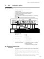
Connecting the Power Supply and Ground
• Use 600V vinyl-insulated power lead (JIS C 3307) as the power supply lead.
• Obtain the SRF206/212/224 power supply from a single-phase instrumentation
power supply not subject to excess noise.
• If the power supply generates excessive noise, add an insulating transformer,
and use a line filter.
Recommended line filter: Yamatake Corporation 81446364-001.
• Keep the wiring from the line filter as short as possible. Bundling this wiring
together is effective against electrical noise.
• After providing anti-noise countermeasures, do not bundle primary and
secondary power leads together, or pass them through the same piping or wiring
duct.
Connect the SRF206/212/224 by one-point grounding to the protective ground
terminal. Do not perform any jump wiring. When it is difficult to ground shielded
cables, prepare a separate ground terminal (earth bar).
• Grounding type:
Lower than 100Ω
• Grounding conductor:
Annealed copper wire more than 2mm2
(AWG14) or equivalent or thicker wire
• Grounding conductor length:
Max. 20m
Instrument
power supply
200/200V
100/100V
Insulation
transformer
Recommended product
line filter
81446364-001
1
100 to 240Vac
50/60Hz
SRF206/212/224
3
1
2
E
2
Other circuits
Ground
4
3
Ground
Handling Precautions
Take rush current into consideration when installing a power switch or
use outside the SRF206/212/224.
3-5
Chapter 3. INSTALLATION AND WIRING
3 - 5
I/O Signal Leads
(1) Thermocouple input signal lead
In the case of thermocouple input, connect the bare thermocouple lead to the
terminal. If the thermocouple is located a long way from the
SRF206/212/224, or the thermocouple is connected to a terminal, extend the
connection using a compensating lead and then connect to the terminal. Use
shielded compensating leads only.
(2) Resistance temperature detector (RTD)
• Use the three conductors.
• For the conductor, use JKEV-SB (JCS4364) shielded instrument cable or
equivalent product. (This is commonly called as “twisted shielded cable for
instruments.”)
• The wiring resistance is 10Ω or less per conductor.
• Balance the resistances of the three conductors so that they are the same
values.
(3) Analog inputs other than thermocouple and resistance temperature detector
(RTD) and digital I/O leads
• Use twisted shielded cable for instruments.
• Shielded, multi-core microphone cord (MVVS) can be used if there is little
electromagnetic induction.
Note
• Use no-voltage contact inputs, and assign these contacts for minute currents.
(input no-load voltage: approx. 5V, input short-circuit current: approx.
6mA)
• Hold contact signals for 0.5s or more.
Handling Precautions
Be careful not to short-circuit across communications terminals SDA
and SDB, or across RDA and RDB. Otherwise, this might damage the
communications path.
3-6
Chapter 3. INSTALLATION AND WIRING
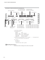
■ Wiring Analog Inputs
Channels
1 to 6
Channels
7 to 12
Channels
13 to 18
Channels
19 to 24
1
7
13
1
7
13
1
7
13
1
7
13
2
8
14
2
8
14
2
8
14
2
8
14
3
9
15
3
9
15
3
9
15
3
9
15
4
10
16
4
10
16
4
10
16
4
10
16
11
17
5
11
17
5
11
17
12
18
6
12
18
6
12
18
5
11
17
5
6
12
18
6
Channel No.
Channel 1
Channel 2
Channel 3
Channel 4
Channel 5
Channel 6
Channel No.
Channel 7
Channel 8
Channel 9
Channel 10
Channel 11
Channel 12
DC voltage
Connection
+
Thermocouple
+
Channel No.
Channel 13
Channel 14
Channel 15
Channel 16
Channel 17
Channel 18
Channel No.
Channel 19
Channel 20
Channel 21
Channel 22
Channel 23
Channel 24
Resistance temperature detector
A
B
C
DC current input
A
✽
B
C
✽ Attach a current-voltage converting fixed resistor to the
terminal plate.
* A 250Ω precision resistor is available as an option.
(model No.: 81401325 or 81446642-001)
For details, see “Optional parts” on page 1-4.)
Note
Each of the channels are mutually isolated. (excluding terminal C for the
resistance temperature detector)
3-7
Chapter 3. INSTALLATION AND WIRING
N
11
21
2
12
22
3
13
23
4
14
24
5
15
25
6
16
26
7
17
27
8
18
28
9
19
10
20
11
2
12
22
3
13
23
21
4
14
24
5
15
25
6
16
26
7
17
27
8
18
28
29
9
19
29
30
10
20
30
3
Option unit 1
Option unit 2
Option unit 1
Option unit 2
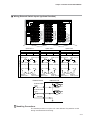
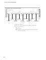
Relay No. Terminal No.
Relay No. Terminal No.
NO COM NC
1 11 21
2 12 22
3 13 23
4 14 24
5 15 25
6 16 26
NO COM NC
1 11 21
2 12 22
3 13 23
4 14 24
5 15 25
6 16 26
1
2
3
4
5
6
3-8
1
7
8
9
10
11
12
NO
Connection
2
1
Relay output terminals
1
Relay output terminals
■ Wiring Relay Outputs (optional function)
NC
COM
Internal
circuit
To external equipment
Chapter 3. INSTALLATION AND WIRING
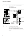
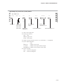
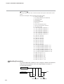
■ Wiring Open Collector Outputs (optional function)
WARNING
Before wiring the SRF206/212/224, check the model numbers of instruments
(including options) and terminal numbers on the affixed labels. When you
have finished wiring, check the numbers again. Wiring the wrong lead to the
wrong terminal might damage the main unit or cause a fire.
CAUTION
Do not connect the power supply with its polarities reversed.
Doing so might damage the recorder.
Do not connect loads that exceed the maximum load current.
Doing so might damage the recorder.
Do not short-circuit loads.
Doing so might damage the recorder.
If necessary, attach a fuse or other overcurrent protection element on the
external load.
Handling Precautions
Use an external power supply of the same voltage as the load.
Otherwise, the clamp diode will not function.
3-9
1
11
2
12
22
3
13
23
21
4
14
24
5
15
25
6
16
26
7
17
27
8
18
28
9
19
29
10
20
30
Open collector output terminals
Chapter 3. INSTALLATION AND WIRING
Option unit 3
Terminal No.
1
2
3
4
5
6
7
8
Signal
Terminal No.
Open collector output 1
11
Open collector output 3
12
Open collector output 5
13
14
Open collector output 7
15
Open collector output 9
16
Open collector output 11
17
Closed at recorder ON
18
Closed at self diagnostics error
Signal
Terminal No.
+Power
Open collector output 2
21
GND
Open collector output 4
22
*2
GND
Open collector output 6
23
+Power
24
Open collector output 8
25
Open collector output 10
GND
*2
26
Open collector output 12
GND
+Power
27
Closed at power ON
28
GND *2
GND *2
*1: Mutually isolated
*2: Terminal Nos. 18 and 28, 22 and 23, and 25 and 26 are internally connected at the terminal.
*3: If even one of alarms AL01 to AL15 occurs, a self-diagnostics error will occur.
Internal circuit
External load
+Power
Open collector
output
Load
Open collector
output
Load
GND
+
10 to 29Vdc
Note
Load drive power voltage
Max. load current
OFF leakage current
ON residual voltage
Clamp diode forward current
Clamp diode reverse voltage
3-10
10 to 29Vdc (including power ripple)
70mA (per single output)
0.1mA max.
1.6V max.
70mA max.
40V max.
*1
*1
*1
Chapter 3. INSTALLATION AND WIRING
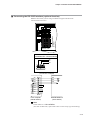
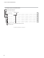
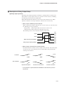
■ Wiring External Switch Inputs (optional function)
1
2
N
1
11
21
1
11
21
1
11
2
12
22
2
12
22
2
12
22
3
13
23
3
13
23
3
13
23
21
4
14
24
4
14
24
4
14
24
5
15
25
5
15
25
5
15
25
6
16
26
6
16
26
6
16
26
7
17
27
7
17
27
7
17
27
8
18
28
8
18
28
8
18
28
9
19
29
9
19
29
9
19
29
10
20
30
10
20
30
10
20
30
Option unit 2
Option unit 1
Terminal No.
7
8
17
18
Connection
External
switch input 1
7
17
No.1 Common
Option unit 2
Terminal No.
7
8
27
28
External
switch input 2
External
switch input 3
17
18
External
switch input 5
7
17
No.5 Common
27
No.2
(internally connected at terminal)
No.3 Common
8
18
Option unit 3
No.4
28
External
switch input 4
Option unit 3
Terminal No.
27
28
External
switch input 6
27
No.6
(internally connected at terminal)
No.7 Common
8
18
External
switch input 7
External switch
External switch
input terminals
Option unit 1
External switch
input terminals
External switch
input terminals
3
No.8
28
External
switch input 8
9
10
29
30
19
20
External
switch input 9
External
switch input 10
9
19
No.9 Common
29
No.10
(internally connected at terminal)
No.11 Common
10
20
External
switch input 11
No.12
30
External
switch input 12
Internal circuit
Vcc
External switch
input
External switch
input
Common
Handling Precautions
The terminal positions on option unit 3 are different. Pay attention to this
during instrumentation and wiring.
3-11
Chapter 3. INSTALLATION AND WIRING
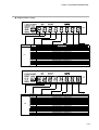
■ Connecting the RS-485 Interface (optional function)
Read this item when you are using a model that supports the RS-485
communications function.
The following shows an example with the RS-485 interface connected. In this
example, the recorder is the slave station:
(connection example)
DIGITRONIK unit (slave station)
1
1
2
N
11
21
2
12
22
3
13
23
4
14
24
5
15
25
6
16
26
7
17
27
8
18
28
9
19
10
20
SDA
SDB
RDA
RDB
SG
Terminator resistor
Terminator resistor
29
30
Option unit 1
Communications
terminals
3
FG
Shielded cable
Master station
RDA
RDB
SDA
SDB
SG
FG
DIGITRONIK unit (slave station)
RS-485
(Yamatake CPL communications)
SDA
SDB
RDA
RDB
SG
SDA
SDB
SG
9
19
29
10
20
30
(internally
connected at
terminal)
RDB
RDA
Shielded cable
FG
Shielded cable
Terminator resistor
Terminator resistor
DIGITRONIK unit (slave station)
SDA
SDB
RDA
RDB
SG
FG
Handling Precautions
Be sure to connect SG terminals each other.
Failure to do so might cause unstable communications.
Provide terminators of resistance 150Ω±5%, 1/2W min. at both ends of the
communications path.
Grounding of the shielded FG terminal should be carried out at only one end and
not both ends.
3-12
Chapter 3. INSTALLATION AND WIRING
■ Connecting the RS-232C Interface (optional function)
Read this item when you are using a model that supports the RS-232C
communications function.
1
2
N
1
11
2
12
22
3
13
23
4
14
24
5
15
25
6
16
26
7
17
27
8
18
28
9
19
29
10
20
30
21
Communications
terminal
3
Option unit 1
RS-232C
(Yamatake CPL communications)
SD
RD
SG
9
19
29
10
20
30
(connection example)
SD
RD
SG
3
2
5
SG
RS
7
CS
8
DR
CD
ER
RD
SD
6
1
4
Host computer
(master station)
DIGITRONIK unit
(slave station)
Note
Cable model No.: CBL232FNZ02
(2m cable for RS-232C, 9pin D-Sub socket contact-crimp-type terminal lug)
3-13
Chapter 4.
4 - 1
PREPARATION AND OPERATION
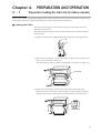
Preparation (loading the chart and ink ribbon cassette)
When a new recorder is shipped, the folding chart (hereafter referred to as the chart) and ink ribbon cassette are not
loaded. When using this recorder for the first time, load the chart and ink ribbon cassette.
■ Loading the Chart
The chart can be loaded by removing chart cassette from the body even if it is
attached to the main unit.
The following describes how to load the chart with the chart cassette attached to
the main unit:
(1) Before you load the chart, lightly fan the chart as shown in the figure below:
(2) Open the door, pull down on both sides of the top edge of the chart guide, and
draw out the chart guide towards you.
The chart guide can also be opened out downwards. (For details, see page 4-4.)
Chart guide
(3) Press down on the PULL marks on the chart cassette, and pull the chart
cassette towards you. The chart cassette breaks as you pull it down. However,
slightly lift the entire cassette and lower it down until it becomes horizontal.
PULL
Enlarged view
4-1
Chapter 4. PREPARATION AND OPERATION
(4) Hold the handle on the chart holder on the rear of the chart cassette and lift up
the handle to open the chart holder.
The chart holder comes to a stop at the fully open (innermost) position.
Chart holder
Chart holder sheet
Handling Precautions
Prevent the chart holder sheet on the edge of the chart holder from
becoming deformed.
(5) Insert the fanned chart into the chart holder making sure that it is facing the
right way, and bring out the leading edge of the chart towards the chart guide.
Load the chart so that the side of the chart with the printed scale is facing up
and the end (red) mark is innermost.
Chart holder
End mark
side
Chart
Round holes
Oblong holes
Handling Precautions
A chart feed error will occur if the chart is not loaded correctly.
Make sure that the oblong holes of the chart are located on the right
side.
(6) Hang three or five folds from the leading edge of the chart on the chart guide
side, and correctly align them on the sprockets.
Sprockets
Sprockets
Round holes Oblong holes
Left side
4-2
Right side
Chapter 4. PREPARATION AND OPERATION
(7) Push the chart holder in so that it goes into the left and right latches.
Chart holder
Detailed view
of latch
(8) Push in the chart holder so that it is firmly hooked onto the left and right
latches of the chart guide.
Detailed view of latch
Handling Precautions
Make sure that the time line on the chart is parallel with the top edge of
the chart guide when viewed from the front.
(9) Correctly return the chart cassette to its original position, and push in the PULL
marks on the left and right until you hear the chart cassette click into place.
(10)To remove the chart cassette from the main unit to load the chart, lift up the
chart cassette in the state in step (3) and draw out.
Handling Precautions
Before you start recording after you have removed and re-attached the
FEED
chart cassette, press the
key to feed the chart about one fold to
make sure that the chart is being fed correctly.
4-3
Chapter 4. PREPARATION AND OPERATION
Note
The chart guide can also be drawn out downwards. Press the hooks on both
sides at the bottom of the chart guide and draw out the chart guide towards
you.
Chart guide
Press inwards and
draw out towards you.
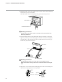
■ Loading the Ink Ribbon Cassette
(1) Open the door and open the display setup unit towards you by pulling on the
protrusion at the bottom left of the unit.
(2) To replace the ink ribbon cassette, remove the old ink ribbon cassette.
Push the release knob at the bottom left of the ink ribbon cassette up and swing
the ink ribbon cassette out from the right side.
Gear
Do not push with
excessive force. Doing
so might cause faulty
operation.
4-4
Chapter 4. PREPARATION AND OPERATION
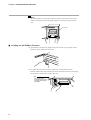
(3) Insert the protrusion on the right of the new ink ribbon cassette into the hole on
the ink ribbon cassette holder, and push in the release knob until you hear it
click into place. The release knob enters the holder more easily if you push it in
while rotating the ribbon feed knob.
Hole
Ribbon feed
knob
Protrusion
(4) Make sure that the ink ribbon is inserted correctly between the wire dot head
and the chart.
Wire dot head
Ink ribbon
Chart
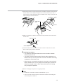
(5) Turn the ribbon feed knob on the ink ribbon cassette in the direction of the
arrow to take up any slack in the ribbon.
Handling Precautions
• You cannot turn the ribbon feed knob on the ink ribbon cassette
when the power is ON.
• The ribbon will not be fed smoothly if the ink ribbon cassette is not
loaded correctly. This may result in color drift or the ribbon becoming
entangled in the wire dot head.
• When you are not using the recorder for a long time, remove the ink
ribbon cassette, put it in a vinyl bag and seal the bag to prevent the
ribbon from drying. If the ink dries, prints will be faint or recording
may no longer be possible.
(6) Return the display setup unit to its original position.
Note
• Model No. of ink ribbon cassette: 81407408-001 (1 p’ce)
• The service life of the ink ribbon is about three months when feeding at a
chart feed speed of 20mm/h.
4-5
Chapter 4. PREPARATION AND OPERATION
4 - 2
Operation
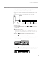
■ Turning the Power ON
The recorder’s power switch is located at the top right on the front when you open
the door.
Pressing the power switch turns the power ON, and pressing it again turns the
power OFF.
The internal check is automatically carried
out within 30s of turning the power ON, and
the recorder then enters the normal operating
mode.
During the internal check, the model No. is
displayed followed by the version number and
then the date.
Handling Precautions
During the internal check, the external switch inputs, relay outputs and
open collector functions do not work.
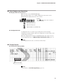
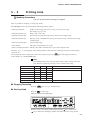
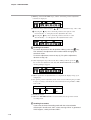
■ Starting/stopping Recording
RCD
To start/stop recording, press the
key.
RCD
If you press the
key, the LED on the key lights and recording starts.
If you press this key again, the LED goes out, and recording stops.
When recording starts, the following items are printed out:
This is called “initial printing.”
• Year/Month/Date
• Time (h/min)
• Recording format
• Chart feed speed
• Recorder ID No. (The ID No. is not printed when “00” is set as the ID No.)
Handling Precautions
• Initial printing is not carried out when the power is turned OFF and
then ON again in a recording start state.
At this time, the chart is automatically fed about 1mm, and then
recording is resumed. The same operation is carried out in the event
of an instantaneous power interruption.
• The recording stop/start state is held in memory even if the power is
OFF. The same status is returned to when power is next turned ON.
LOCK
EVNT
CLK
RNG
UF1
(example of starting recording)
4-6
CH
COPY
SPD
SYS
SCL
EVNT
SET
DATA
C
UF2
ACK
ENT
AUTO MAN
FEED
DMD
RCD
DISP
CLK
Chapter 4. PREPARATION AND OPERATION
■ Advancing the Chart
To advance the paper position when recording is stopped, hold down the
key.
LOCK
EVNT
CLK
RNG
CH
COPY
SPD
SYS
SCL
UF1
EVNT
SET
DATA
C
UF2
ENT
AUTO MAN
ACK
FEED
FEED
DMD
RCD
CLK
DISP
To stop chart feed, release your finger from the key.
Handling Precautions
FEED
• You cannot operate the
key during recording.
FEED
• You cannot move the chart backwards using the
key. To move
the chart backwards, remove the chart cassette, manually fold back
the chart to its original position, and load the chart cassette into the
main unit again.
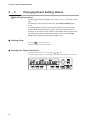
■ Selecting the Display Mode
LOCK
EVNT
CLK
RNG
CH
COPY
SPD
SYS
SCL
UF1
EVNT
SET
DATA
C
UF2
ACK
ENT
AUTO MAN
FEED
DMD
RCD
CLK
DISP
DISP
You can select four display modes by pressing the
key.
AUTO indicator
This mode successively displays the PV value of each channel at 4s intervals.
MAN indicator
This mode displays the PV value of specific channels. To move to the next
channel, press the
or
key.
CLK indicator (year/month/date)
This mode displays the date.
CLK indicator (time)
This mode displays the time.
4-7
Chapter 4. PREPARATION AND OPERATION
■ Recording a Specific Table
You can record a table (tabulation) of current PV values by pressing the
key.
LOCK
EVNT
CLK
RNG
CH
COPY
SPD
SYS
SCL
UF1
EVNT
SET
DATA
C
UF2
During recording
ENT
AUTO MAN
ACK
FEED
DMD
DMD
RCD
CLK
DISP
: A table of PV values is recorded overlaying trend data.
The tabulation time varies according to the chart feed
speed.
During recording stop : Tabulation starts immediately, and ends in about 3min on
24-dot model recorders.
DMD
To cancel tabulation midway, press the
key again.
Pressing this key immediately stops tabulation. If you press this key during a
RCD
recording stop, tabulation starts. If you press the
key during tabulation,
recording starts after tabulation ends.
Tabulation is sometimes not performed at fixed times while tables are being
recorded. For details of required recording times, see page 6-31.
Required Table Recording Times at a Chart Feed Speed of 20mm/h
(recording example when the
(recording example when the
during tabulation)
4-8
Model
Required Time
6-dot printing
22min
12-dot printing
33min
24-dot printing
54min
DMD
DMD
key is pressed during recording)
key is pressed during a recording stop and the
RCD
key is pressed
Chapter 4. PREPARATION AND OPERATION
■ Other Displays and Operations
● Display when an event occurs
When an event occurs, the EVNT LED lights.
When the display mode is set to AUTO or MAN, the status of the event is
displayed for the channel where the event occurred.
(Example)
CH EVNT
The
(HIGH) event occurs on channel 1
(PV value: 520.4)
:
HIGH (upper limit) event
:
LOW (lower limit) event
:
HIGH and LOW occur simultaneously
● Configuration lock
“Configuration lock” is a feature for preventing the user from changing
configuration setups by mistake. When the configuration is locked, setups can be
confirmed but not changed.
When the configuration is locked, the LOCK LED lights. For details on how to
cancel configuration lock, see ■ Canceling Configuration Lock (page 5-4).
Note
Configuration lock can be set on the user function keys.
■ Printout Details
● Printout messages (purple)
Printout messages
Note
For details, see 6-12 Message Setup (page 6-32).
4-9
Chapter 4. PREPARATION AND OPERATION
● Example of trend + tabulation recording
● Example of trend + schedule demand
Same as trend + tabulation recording
● Example of trend recording
4-10
Chapter 4. PREPARATION AND OPERATION
● Example of fixed interval tabulation
● Example of fixed time tabulation
Same as fixed interval tabulation recording
4-11
Chapter 4. PREPARATION AND OPERATION
■ Replacing the Chart
CAUTION
Load the chart and ink ribbon cassette either with the power OFF or with the
recorder stopped (the RCD LED should be OFF). Do not push the cassette
with excessive force. Doing so might force a movement of the ink ribbon
cassette holder (see page 4-4), damaging the gear and causing faulty
operation.
First, turn the power OFF, or press the
LED should be OFF).
LOCK
EVNT
CLK
RNG
CH
COPY
SPD
SYS
SCL
UF1
EVNT
RCD
SET
DATA
C
UF2
ACK
ENT
AUTO MAN
FEED
For the procedure to follow, refer to:
■ Loading the Ink Chart (page 4-1).
4-12
key to stop recording (the RCD
DMD
RCD
DISP
CLK
Chapter 4. PREPARATION AND OPERATION
■ Replacing the Ink Ribbon Cassette
CAUTION
Load the chart and ink ribbon cassette either with the power OFF or with the
recorder stopped (the RCD LED should be OFF). Do not push the cassette
with excessive force. Doing so might force a movement of the ink ribbon
cassette holder (see page 4-4), damaging the gear and causing faulty
operation.
First, turn the power OFF, or press the
LED should be OFF).
LOCK
EVNT
CLK
RNG
CH
COPY
SPD
SYS
SCL
UF1
EVNT
RCD
key to stop recording (the RCD
SET
DATA
C
UF2
ACK
ENT
AUTO MAN
FEED
DMD
RCD
CLK
DISP
For the procedure to follow, refer to:
■ Loading the Ink Ribbon Cassette (page 4-4).
4-13
Chapter 5.
5 - 1
BASIC CONFIGURATION
Introduction
To use the SRF206/212/224, you must first select the input range type, and set the recording scale, chart feed
speed and other items. This setup is called “configuration.”
Configuration is sometimes already set up by the device manufacturer in which the SRF206/212/224 is
integrated. If the SRF206/212/224 has not been configured or you want to change the configuration setups, refer to
Chapter 6. DETAILED CONFIGURATION.
On the SRF206/212/224, configuration is divided into two stages:
• For personnel who normally operate the SRF206/212/224
• For personnel who initially set up the SRF206/212/224.
This chapter describes the setup items listed below whose settings are changed relatively often in normal operation.
The configuration is set up in the extended menu. This menu has three menu levels as shown in the figure below.
Menu level 0 has six setup items.
Menu level 1 has an additional five setup items.
Menu level 2 has all setup items.
Chapter 6, DETAILED CONFIGURATION describes all of these setup items.
Configuration Lock Canceled
Menu level 0
Event setup/operation
setup
Chart feed speed
Date/time setup
Configuration lock
List printing
Menu level
Menu level 1
The following items are
added to menu level 0:
Event setup
Chart feed speed setup
System setup
Range setup
Scale setup
Menu level 2
The following items are
added to menu level 1:
Extended menu entry
Calculation setup entry
Calculation setup
Copy setup
Schedule demand setup
Message setup
User function key setup
Extended setup
External switch input setup
Internal contact input setup
Relay output setup
Open collector output setup
Segment table setup
Note
When the configuration is locked, setups can be displayed for confirmation
but not changed. (The configuration lock can be canceled at any time.)
Handling Precautions
Data setups can be changed during recording. However, note that
once range type or other items are changed, display or recording
sometimes malfunctions temporarily.
5-1
Chapter 5. BASIC CONFIGURATION
5 - 2
Basic Key Operations at Setup,
Configuration Lock and Menu Levels
■ Basic Key Operations at Setup
This section describes common operations at setup.
The figure below shows the display setup unit.
● To start configuration setup
Press the
LOCK
EVNT
CLK
RNG
SET
key.
CH
COPY
SPD
SYS
SCL
UF1
EVNT
SET
DATA
C
UF2
ACK
ENT
AUTO MAN
FEED
DMD
RCD
● To change configuration items
Press the SET key to advance to the next display number.
● To quit configuration
Pressing the
5-2
DISP
key in any situation quits configuration.
DISP
CLK
Chapter 5. BASIC CONFIGURATION
● To advance to the next display number
Press the
key. The cursor shifts to the display number digit (red LED). Press
the
/
keys to shift the display number.
Note
If you have not changed the numerical values of a setup item, pressing the
ENT
key shifts the display number without changing the setup.
● To change data
Shift the cursor (blinking digit) using the
Press the
/
/
keys to DATA.
keys to determine the data, and set the data with the
ENT
key.
Pressing the
/
keys increments/decrements numerical values to increase or
decrease digits.
When the valid maximum or minimum value of the data is reached, pressing the
/
keys does not change the numerical value. To set the numerical value,
press the
ENT
key.
Note
To cancel changing of data midway, press either of the following keys without
ENT
pressing the
key. Any changes made to the currently displayed data at
this time are implemented.
DISP
key: Quits configuration
ENT
key:
Advances to the next setup.
You can advance the display number without changing the data by pressing
the
/
keys after shifting the cursor to the display number digit (red
LED).
Handling Precautions
If a setting value is in error, all data will blink when you press the
ENT
key. If this happens, press any key to return to the entry display.
Check the setting values, and reset them if necessary.
5-3
Chapter 5. BASIC CONFIGURATION
■ Canceling Configuration Lock
When the configuration is locked, the LOCK LED lights and the configuration
setup cannot be changed.
LOCK
EVNT
CLK
RNG
CH
COPY
SPD
SYS
SCL
UF1
EVNT
SET
DATA
C
UF2
ACK
ENT
AUTO MAN
FEED
DMD
RCD
CLK
DISP
To cancel configuration lock, follow the procedure below:
(1) Press the
SET
key to select SYS.
(2) Change the configuration lock setting from “1” to “0” in display number 1.
(3) Press the
ENT
key.
The LOCK LED goes out to indicate that the configuration lock is canceled.
5-4
Chapter 5. BASIC CONFIGURATION
■ Changing the Menu Level
You can change the menu level so that you can initially set the range type,
recording scale and other setup items.
(1) Press the
keys.
SET
key to select SYS. Select display number 3 using the
/
(2) Change the menu level.
(3) Press the
ENT
key.
5-5
Chapter 5. BASIC CONFIGURATION
5 - 3
Changing Event Setting Values
Handling Precautions
Event setting values are displayed only when “H” or “L” is set as the event
type.
For details on how to set up event types, see 6-3 Event Setup (page
6-11).
The decimal point position of event setting values is the decimal point
position determined by the range code in the case of range codes 10
onwards. In the case of range code 00 to 06 voltage inputs, this becomes
the engineering range decimal point position that is set in 6-7 Range
Setup, range setup procedure step (8) (page 6-19).
■ Starting Setup
SET
Press the
key to select EVNT.
Make sure that the EVNT LED lights.
■ Selecting the Target Channel No.
Select the channel No. to be set using the
/
keys.
The following example shows the display setup unit when channel 2 is selected:
LOCK
EVNT
CLK
RNG
UF1
5-6
CH
COPY
SPD
SYS
SCL
EVNT
SET
DATA
C
UF2
ACK
ENT
AUTO MAN
FEED
DMD
RCD
DISP
CLK
Chapter 5. BASIC CONFIGURATION
■ Selecting the Target Event No.
Up to four events can be set to a single channel. Select which event No. is to be
set. Event No.1 will be displayed with the target channel selected.
Shift the cursor to the display number digit, and select the digit using the
/
keys.
The following example shows the display setup unit when event setting value is
selected:
LOCK
EVNT
CLK
RNG
CH
COPY
SPD
SYS
SCL
UF1
EVNT
SET
DATA
C
UF2
ACK
ENT
AUTO MAN
FEED
DMD
RCD
CLK
DISP
■ Enabling Changing of Event Setting Values
• When you can select the target event No. of the target channel, you can change
that event setting value.
• Pressing the
/
keys shifts the cursor from the channel to the lowermost
digit of the setup item at DATA, and DATA is no longer zero-suppressed.
■ Entering Event Setting Values
Enter event setting values using the
/
or
/
keys.
ENT
When you have set the numerical values, press the
key. This registers the
setting value to memory, and automatically advances the display to the next
display number.
5-7
Chapter 5. BASIC CONFIGURATION
5 - 4
Changing the Date/Time
Handling Precautions
If both the date and time are in error, all data will blink when you press the
ENT
key to notify that entry is no longer possible. If this happens, press
any key to return to the entry display.
The number of seconds in the time setting are reset (so that counting starts
ENT
from “00”) when you press the
key, only when the numerical values
ENT
for the time setting are changed. If you press the
key without making
any changes to the numerical values for the time setting, the date setting
display will be redisplayed, and the number of seconds will not be reset.
■ Starting Setup
Press the SET key to select CLK.
Make sure that the CLK LED lights.
LOCK
EVNT
CLK
RNG
CH
COPY
SPD
SYS
SCL
UF1
EVNT
SET
DATA
C
UF2
ENT
AUTO MAN
ACK
FEED
DMD
RCD
CLK
DISP
■ Changing the Date
The date is arranged in order year (lower two digits of Western calendar), month
then day. Shift the cursor to the part of this item that you want to change using the
/
keys, and change the numerical value using the
/ keys. Leap years
in dates are automatically adjusted. To set the year “2000”, enter “00” as the year.
ENT
When you press the
key, the time setting screen is redisplayed.
■ Changing the Time
The time is arranged in order hours (24h clock) then minutes. Shift the cursor to
the part of this item that you want to change using the
/
keys, and change
the numerical value using the
setup display is redisplayed.
LOCK
EVNT
CLK
RNG
UF1
5-8
CH
COPY
SPD
SYS
SCL
EVNT
/
keys. When you press the
ACK
ENT
AUTO MAN
FEED
key, the data
SET
DATA
C
UF2
ENT
DMD
RCD
DISP
CLK
Chapter 5. BASIC CONFIGURATION
5 - 5
Printing Lists
Handling Precautions
Lists can be printed when printing has stopped.
Lists are printed for checking or saving setup details.
The SRF206/212/224 is provided with the following printing options:
• Print specified lists:
Outline of main setup items such as range, scale and event setup
For details, see page 5-10.
• Print function lists (A):
Range setup, scale setup
• Print function lists (B):
Event setup, external switch input setup, internal contact input setup
• Print function lists (C):
Message setup, schedule demand setup, user function setup, communications setup,
extended setup
• Print function lists (D):
Segment table setup
• Print all lists:
All setups of function lists (A) to (D)
• Print communications lists: Details set by CPL communications or personal computer loader
Selecting “1” to “7” starts printing of lists. When printing of lists ends, the printing list selection is automatically
cleared to “0”.
RCD
To automatically start recording after a list has been printed, press the
key after printing of lists has
started. In this case, the RCD LED lights.
Note
The following table shows the approximate times it takes to print each of the
lists. The time required to print a list varies according to the setup.
6-dot
5min
7min
6min
4min
7min
22min
Specified list
Function lists (A)
Function lists (B)
Function lists (C)
Function lists (D)
All list
Communications list
■ Stopping Recording
RCD
Press the
■ Starting Setup
12-dot
8min
13min
10min
4min
7min
32min
1min
Remarks
Varies according to number of used channels
24-dot
15min
25min
19min
4min
7min
53min
Varies according to details to print out
key to stop recording midway.
SET
Press the
to select SYS.
Make sure that the SYS LED lights.
LOCK
EVNT
CLK
RNG
CH
COPY
SPD
SYS
SCL
UF1
EVNT
SET
DATA
C
UF2
ACK
ENT
AUTO MAN
FEED
DMD
RCD
CLK
DISP
Shift the cursor to the display number digit using the
key, and press the
key to shift to the 2nd display number from where the list is to be printed.
5-9
Chapter 5. BASIC CONFIGURATION
■ Selecting the List to be Printed
Press the
key to shift the cursor to DATA, and select the desired list using the
keys.
/
ENT
Pressing the
key starts printing of lists, and the display advances to the next
display number.
The following example shows printing of specified lists selected:
LOCK
EVNT
CLK
RNG
CH
COPY
SPD
SYS
SCL
UF1
EVNT
SET
DATA
C
UF2
ACK
ENT
AUTO MAN
FEED
DMD
RCD
CLK
DISP
■ Stopping List Printing Midway
To stop list printing midway, shift to display number 2, enter “0” using the
ENT
/
keys, and press the
key.
(example of specified list printing)
■ Print Communications List
(example of communications list printing)
5-10
Chapter 5. BASIC CONFIGURATION
■ Print Specified Lists
With print specified lists, all items in channels for which recording is currently set
to OFF are not printed.
● Print items
• Header
Date/time (h:min), recording format, No.1 or No.2 chart feed speed, fixed
date/fixed time interval, recorder ID No.
Each of these printing items are printed unconditionally as the header. (The
header is printed even if recording of all channels is set to OFF.)
• Channel No./Tag
• Range code/PV bias
The PV bias is printed as “-” for the communications input range and ON/OFF
input range.
• No.1, No.2 scale (scale upper/lower limit)
The No.2 scale upper and lower limits are printed as “-” on channels on which
the scale selection setting is set to OFF.
The scale lower limit is printed as “%” and the scale upper limit is printed as “-”
for the ON/OFF range.
When scale selection is not set to OFF, “#” is printed appended to the currently
selected scale.
• Event setup 1 to 4 (event setting value, event type)
Events whose event operation setting is set to OFF are printed as “OFF” and the
event setting values are not printed.
Even events for which recording is set to OFF are printed unless the event type
is OFF.
5-11
Chapter 5. BASIC CONFIGURATION
● Example of details printed by print specified lists
Time of list printing*1
No.1 chart feed speed
No.2 chart feed speed
Fixed interval timer
Fixed time interval timer
Recording format*2
Tag
Channel*1
PV bias
Range code table
See page 6-47.
Recorder ID No.
No.1 scale lower limit
No.1 scale upper limit
No.2 scale lower limit
No.2 scale upper limit*3
No.1 event setting value
No.2 event setting value
No.3 event setting value
No.4 event setting value
No.1 event type*4
No.2 event type*4
No.3 event type*4
No.4 event type*4
*1: This is not a setup item.
*2: Recording format
TREND:
TREND + TAB:
TREND + SDMD:
TAB (TIME):
TAB (ITVL):
trend
trend + tabulation
trend + schedule demand
fixed interval tabulation
fixed time tabulation
*3: When scale switching method is set to “0” (OFF), “--- ---” is displayed as the
No.2 scale lower limit/No.2 scale upper limit.
*4: event type
H: upper limit
L: lower limit
-: When set to OFF, “OFF” is printed.
Handling Precautions
Channels for which recording is set to OFF are not printed.
5-12
Chapter 5. BASIC CONFIGURATION
■ Print All Lists
● Example of print all lists (range) details
No.1 chart feed speed
No.2 chart feed speed
Time of list printing*1
Tag
Recording format*2
Burnout*4
Recorder ID No.
Range code table
See page 6-47.
Channel*1
Segment
table use*5
PV filter
Recording mode*3
Fixed interval timer
Fixed time interval timer
PV bias
Calculation parameter 1, 2, 3
Input calculation type*6
Measurement range lower limit upper limit
Engineering range lower limit lower limit
*1: This is not a setup item.
*2: Recording format
TREND:
TREND + TAB:
TREND + SDMD:
TAB (TIME):
TAB (ITVL):
trend
trend + tabulation
trend + schedule demand
fixed interval tabulation
fixed time tabulation
*3: Recording mode
OFF: OFF
DISP: Display
RCD: Display + recording
DI:
digital input-dependent
*4: “-” is printed in the case of inputs other than a thermocouple.
*5: Segment table use
OFF: Use disabled
EQL1: Use segment table 1
EQL2: Use segment table 2
EQL3: Use segment table 3
*6: Input calculation type
NORMAL:
OFF (PV value)
PICH-P2CH:
A channel - B channel
DEV (DATA-): Fixed value - current channel
DEV (-DATA): Current channel - fixed value
INTEGRAL:
Integrating calculation
F.VAL CALC: F value calculation
%RH CALC: Relative humidity calculation
5-13
Chapter 5. BASIC CONFIGURATION
● Example of print all lists (scale) details
No.2 scale
lower limit*2
No.1 scale
lower limit
Channel*1
No.1 scale
upper limit
Engineering unit
No.2 scale
upper limit*2
Auto-switching
point*2
Scale switching
method*3
Scale switching
differential*2
*1: This is not a setup item.
*2: When scale switching method is set to “0” (OFF), “-” is displayed.
*3: Scale switching method
OFF: OFF
AUTO: Automatic
REM: Selected by internal contact input, external switch input or CPL
communications input
5-14
Chapter 5. BASIC CONFIGURATION
● Example of print all lists (events) details
Channel*1
No.1 event
No.2 event
No.3 event
No.4 event
Event setting
value*3
Event type
selection*2
Event output
destination*3, *4
Event differential*3
Event recording*3, *5
*1: This is not a setup item.
*2: Event type selection
OFF: OFF
HIGH: Upper limit
LOW: Lower limit
*3: When event type selection is set to “0” (event OFF), “-” is displayed.
*4: Event output destination
-:
OFF
RELAYn:
Output to No.n relay
O.C.DOn:
Output to No.n open collector output
INTERNALn: Output to No.n internal contact input
*5: Event recording
OFF: Event recording OFF
ON:
Event recording ON
5-15
Chapter 5. BASIC CONFIGURATION
● Example of print all lists (DI/DO) details
Internal contact input setup
External switch input setup
Setup description
Open collector output
No.1 external switch input setup
setup
Relay output setup
For details of setup items, see page 6-9.
5-16
Chapter 5. BASIC CONFIGURATION
● Example of print all lists (other) details
User function assignment 1 to User function assignment 8
Schedule demand
time setup ON/OFF
Schedule demand No.1 time setup to No.8 time setup
No.1 message No.2 message No.3 message No.4 message
No.5 message No.6 message No.7 message No.8 message
Communications
hardware option*1
Recording
start
ON/OFF
Count
function
selection*4
Date type
selection*6
Device address
Communications
access rights*2
Recording time
ON/OFF
Configuration
lock*3
User function 1 key basic registration
User function 2 key basic registration
Standard
contact
compensation
*7
Menu level*5
Atmospheric
pressure
Thermal
resistance
Recording color
selection*8
Scale recording
ON/OFF
Communications method
(baud rate, data length,
stop bit length)
*1: This is not a setup item.
*2: Communications access rights
RD:
Read only
R/W: Read/write
*3: Configuration lock
OFF: Unlocked
ON:
Locked
*4: Count function selection
BAT: Batch count
BIN: Binary count
*5: Menu level
STD: Display only level 0 items.
EXD1: Display level 0 and 1 items.
EXD2: Display all setup items.
*6: Date type selection
JPN: JP (YY, MM, DD)
ENG: US (MM, DD, YY)
EC:
EU (DD, MM, YY)
*7: Standard contact compensation
ON:
Located internally
OFF: Located externally
*8: Recording color selection
STD: STD (purple, red, green, blue, brown, black)
DIN: DIN (purple, red, black, green, blue, brown)
5-17
Chapter 5. BASIC CONFIGURATION
● Example of print all lists (segment table) details
X-axis
Y-axis
point 01
•
•
•
•
•
•
•
point 15
Segment table 1
5-18
Segment table 2
Segment table 3
DETAILED CONFIGURATION
Chapter 6.
6 - 1
Introduction
This chapter describes how to setup configuration items that are initially set on the SRF206/212/224.
Before you can change configuration settings, the configuration lock must be canceled. For details on how to
cancel the configuration lock, see ■ Canceling Configuration Lock (page 5-4).
This menu has three menu levels 0, 1 and 2.
Menu level 0 is for setting up event setting, event types, chart feed speed, date/time and other items, and is for
carrying out list printing.
Menu level 1 is for setting up range types, recording scales, recording format, event differential, and other system
settings.
Menu level 2 is for setting up all configuration setup items.
Handling Precautions
Configuration can be setup also during recording. However, if the range
type or other setup items are changed, display and recording sometimes
becomes temporarily abnormal.
Note
For details on event setting values, date/time setup and list printing to be
configured in menu level 1, see Chapter 5. BASIC CONFIGURATION.
● Display Configuration
Power ON
Operation display
DISP
DISP
SET
DISP
Schedule demand
setup
Event setup
S D.
SET
SET
Chart feed
speed setup
E S.
SET
Message setup
N.S.
SET
SET
U
Date/time setup
SET
SET
1
*1
Internal contact
input
setup
Relay output
setup
I S.
User function key
setup
1.
SET
User function key
setup
SET
R O.
Open collector
output setup
U 2.
SET
SET
D O.
Extended setup
SET
E T.
Range setup
DISP
DISP
DI/DO-related setup
mode
External switch
input setup
Extended setup mode
Data setup
SET
DISP
CLK (h:min)
DISP
DISP
System setup
DISP
CLK (date)
MAN
AUTO
SET
*2
2
Scale setup
SET
Segment table setup mode
Copy function
X-axis of
segment table 1
SET
3
X-axis of
segment table 2
T A.
SET
T C.
SET
Y-axis of
segment table 1
Y-axis of
segment table 2
T B.
SET
X-axis of
segment table 3
T E.
SET
T D.
SET
Y-axis of
segment table 3
T F.
SET
Calculation setup
*1 Migration from extended menu entry
*2 Migration from calculation setup entry
6-1
Chapter 6. DETAILED CONFIGURATION
6 - 2
Configuration Data and Factory Settings
Note
The setup items that can be changed varies according to the menu level. For details
see page 6-1.
■ Event Setup (individual channels): EVNT
Display No.
1
2
3
4
5
6
7
8
5
6
7
8
5
6
7
8
9
A
B
C
Setup Item
No.1 event setting value
No.2 event setting value
No.3 event setting value
No.4 event setting value
No.1 event type selection
No.2 event type selection
No.3 event type selection
No.4 event type selection
No.1 event output destination
No.2 event output destination
No.3 event output destination
No.4 event output destination
No.1 event recording ON/OFF
No.2 event recording ON/OFF
No.3 event recording ON/OFF
No.4 event recording ON/OFF
No.1 event differential
No.2 event differential
No.3 event differential
No.4 event differential
Setup Description
-19999 to +29999
-19999 to +29999
-19999 to +29999
-19999 to +29999
- (OFF)/L (LOW)/H (HIGH)
- (OFF)/L (LOW)/H (HIGH)
- (OFF)/L (LOW)/H (HIGH)
- (OFF)/L (LOW)/H (HIGH)
0 to 36
0 to 36
0 to 36
0 to 36
0 (OFF)/1 (ON)
0 (OFF)/1 (ON)
0 (OFF)/1 (ON)
0 (OFF)/1 (ON)
0 to 29999
0 to 29999
0 to 29999
0 to 29999
Menu Level
Factory Setting
0
0
0
0
0
0
0
0
0
0
0
0
0
0
0
0
1
1
1
1
0
0
0
0
Menu Level
Factory Setting
0
1
20
20
1
1
1
00:30
- (OFF)
- (OFF)
- (OFF)
- (OFF)
0
0
0
0
1 (ON)
1 (ON)
1 (ON)
1 (ON)
0
0
0
0
■ Chart Feed Speed Setup: SPD
Display No.
1
2
3
4
Setup Item
No.1 chart feed speed
No.2 chart feed speed
Fixed date interval timer
Fixed time interval timer
Setup Description
1 to 480mm/h
1 to 480mm/h
1: 10min
2: 20min
3: 30min
4: 1h
5: 2h
6: 3h
7: 6h
8: 12h
9: 24h
00:05 to 23:59
■ Date/Time Setup: CLK
Setup Item
Date
Time
6-2
Setup Description
Menu Level
00/01/01 to 99/12/31
00:00 to 23:59
0
0
Factory Setting
Close to Japan standard time
Close to Japan standard time
Chapter 6. DETAILED CONFIGURATION
■ System Setup: SYS
Display
No.
1
2
3
4
5
6
7
8
Setup Item
Configuration lock
List printing start/stop
Menu level
Recording format
Recorder ID No.
Recording time ON/OFF
9
A
Scale recording ON/OFF
Recording color selection
(STD/DIN)
Communications access rights
Device address
B
Communications method
C
Extended menu entry
Setup Description
0 (OFF)/1 (ON)
0: Stop list printing
1: Start specified list printing
2: Start range/scale settings printing
3: Start event and DI/DO settings printing
4: Start MSG, S.DMD, UF and
communications settings printing
5: Start segment table settings printing
6: Start all list printing
7: Start communications list printing
0 to 2
1: Trend
2: Trend + tabulation
3: Trend + schedule demand
4: Fixed interval tabulation (tabulation only)
5: Fixed time tabulation (tabulation only)
0 to 99
0 (OFF)/1 (ON)
0 (OFF)/1 (ON)
1 (STD)/2 (DIN)
1 (read)/2 (read/write)
0 to 127 (setting to “0” inhibits
communications)
1: 4800bps, 8bits, even parity, 1 stop bit
2: 4800bps, 8bits, no parity, 2 stop bits
3: 9600bps, 8bits, even parity, 1 stop bit
4: 9600bps, 8bits, no parity, 2 stop bits
0: Migration disabled
1: Migration to extended setup mode
2: Migration to DI/DO-related setup mode
3: Migration to segment table setup mode
Menu
Level
0
Factory Setting
0 (OFF)
0
0 (stop)
0
0
1
2
1
1
1
1
0
1 (ON)
1 (ON)
1 (STD)
1
1
1 (read)
0
1
1
2
0
6-3
Chapter 6. DETAILED CONFIGURATION
■ Range Setup (individual channels): RNG
Display
No.
Setup Item
Setup Description
1
Recording mode
2
3
4
5
6
7
8
9
A
B
C
d
e
Range code
Digital signal No.
Burnout
Measurement range lower limit
Measurement range upper limit
Engineering range decimal point
Engineering range lower limit
Engineering range upper limit
PV filter
PV bias
Engineering unit
Tag
Calculation setup entry
0 (OFF)/ 1 (display)/ 2 (display +
recording)/ 3 (digital input-dependent)
See Range Code Table (page 6-47).
0 to 62
0 (OFF)/ 1 (UP)/ 2 (DOWN)
-19999 to measurement range upper limit -1
Measurement range lower limit + 1 to 29999
0 (xxxxx) to 4 (x.xxxx)
-19999 to +29999
-19999 to +29999
0 to 15
-19999 to +29999
6 characters
12 characters
0: Entry to calculation setup disabled
1: Entry to calculation setup enabled
Menu
Level
1
Factory Setting
2
(display + recording)
1
1
1
1
1
1
1
1
1
1
1
1
2
05 (±5V)
0
0 (OFF)
1.000
5.000
1 (xxxx.x)
0.0
100.0
0
0.0
Blank
CH1 to 24 (shift to right)
0
■ Calculation Setup (individual channels): RNG
Display
No.
1.
2.
Setup Item
Input calculation type
Calculation parameter 1
Setup Description
0: OFF (PV value)
1: A channel - B channel
2: Fixed value - current channel
3: Current channel - fixed value
4: Integrating calculation
5: F value calculation
6: Relative humidity calculation
Conditions
Menu
Level
Factory Setting
2
0
Setup description
Input calculation type = 1
1 to number of channels
Input calculation type = 2
-19999 to +29999
Input calculation type = 3
-19999 to +29999
Input calculation type = 4
0: s
1: min
Current channel
0.0
0.0
2
0
2: h
3.
Calculation parameter 2
Input calculation type = 5
0.0 to 500.0
Input calculation type = 6
1 to number of channels
Input calculation type = 1
1 to number of channels
Input calculation type = 4
1 to 6
Input calculation type = 5
1 to 6
Input calculation type = 6
0: Large (2.5m/s or more)
121.1
*
Current channel
1
1
2
0
1: Medium (0.5 to 2.5m/s)
2: Small (less than 0.5m/s)
4.
5.
Calculation parameter 3
Segment table use
0 to 10
0: Use disabled
1: Use segment table 1
2: Use segment table 2
3: Use segment table 3
2
0
2
0
* : In channel 1 setup, this factory setting becomes “channel 2”. In other instances, this factory setting becomes
“current channel -1”.
6-4
Chapter 6. DETAILED CONFIGURATION
■ Scale Setup (individual channels): SCL
Display
No.
1
2
3
Setup Item
No.1 scale lower limit
No.1 scale upper limit
Scale switching method
selection
No.2 scale lower limit
4
No.2 scale upper limit
5
Auto-switching point
6
Auto-switching differential
7
*1 At ON/OFF input range
Setup Description
-19999 to +29999 or 0.0 to 98.0*1
-19999 to +29999
0: OFF
1: Automatic
2: Internal contact input, external switch
input or CPL communications
-19999 to +29999 or 0.0 to 98.0*1
-19999 to +29999
-19999 to +29999
0 to 29999
Menu
Level
1
1
Factory Setting
0.0
100.0
1
0
1
1
1
1
0.0
100.0
0.0
0.0
■ Copy Function: COPY
Display
No.
Setup Item
1
2
3
Copy destination channel lower limit
4
Copy source channel
Copy destination channel upper
limit
Copy execution
Setup Description
1 to number of channels
1 to copy destination channel upper limit
Copy destination channel lower limit to
number of channels
0: Execution OFF/end copy
1: Copy all data
2: Copy range, calculation and scale data
3: Copy event data
4: Copy tag data
5: Copy engineering unit data
Menu
Factory Setting
Level
2
1
2
1
2
Maximum channel
2
0
Menu
Level
Factory Setting
2
0
2
00:00
■ Schedule Demand: SYS + S d.
Display
No.
1
2
3
4
5
6
7
8
9
Setup Item
Time setup ON/OFF
No.1 time setup
No.2 time setup
No.3 time setup
No.4 time setup
No.5 time setup
No.6 time setup
No.7 time setup
No.8 time setup
Setup Description
0: Time setup disabled (schedule demand
printing is not carried out)
1: No.1 time setup enabled
2: No.1 and 2 time setup enabled
3: No.1 to 3 time setup enabled
4: No.1 to 4 time setup enabled
5: No.1 to 5 time setup enabled
6: No.1 to 6 time setup enabled
7: No.1 to 7 time setup enabled
8: No.1 to 8 time setup enabled
00:00 to 23:59
6-5
Chapter 6. DETAILED CONFIGURATION
■ Message Setup: SYS + n. S.
Display
No.
1
2
3
4
5
6
7
8
6-6
Setup Item
No.1 message
No.2 message
No.3 message
No.4 message
No.5 message
No.6 message
No.7 message
No.8 message
Setup Description
12 characters
Menu
Level
2
Factory Setting
“MSG1”
“MSG2”
“MSG3”
“MSG4”
“MSG5”
“MSG6”
“MSG7”
“MSG8”
Chapter 6. DETAILED CONFIGURATION
■ User Function Key Setup: SYS + U 1./U 2.
Channel Display
No.
No.
Setup Description
User function 1
key basic
registration
0: OFF
1: Output to internal contact input No.1
2: Call up setup items
2
User function 1
assignment 1
3
User function 1
assignment 2
4
User function 1
assignment 3
5
User function 1
assignment 4
6
User function 1
assignment 5
7
User function 1
assignment 6
8
User function 1
assignment 7
9
User function 1
assignment 8
0 to 32500
When UF1 key basic registration is set to 2:
Sets a value obtained by adding the following cardinal
number to the setup No. of the settings to be registered.
“0” means that nothing is assigned.
Setup Item
Cardinal Number
Event . . . . . . . . . . . . . . . 1nn00
Chart feed speed . . . . . . . 1000
Date/time . . . . . . . . . . . . . 1500
System . . . . . . . . . . . . . . . 2000
Range . . . . . . . . . . . . . . . 2nn00
(Calculation setup is range setup + 5000.)
Scale. . . . . . . . . . . . . . . . 3nn00
Copy . . . . . . . . . . . . . . . . . 6500
Schedule demand. . . . . . . 2500
Message . . . . . . . . . . . . . .3000
Extended . . . . . . . . . . . . .3500
External switch input . . . . .4000
Internal contact input . . . .4100
Relay output . . . . . . . . . . .4200
Open collector output . . . .4300
Segment 1 X-axis . . . . . . .5000
Segment 1 Y-axis . . . . . . .5100
Segment 2 X-axis . . . . . . .5200
Segment 2 Y-axis . . . . . . .5300
Segment 3 X-axis . . . . . . .5400
Segment 3 Y-axis . . . . . . .5500
Item “nn” indicates the channel No.
If the number is an alphabet character (hex), use a value
after converting to a decimal number.
1
User function 2
key basic
registration
1
U 1.
U 2.
Setup Item
0: OFF
1: Output to internal contact input No.2
2: Call up setup items
Menu
Level
Factory
Setting
2
0
0
0
0
0
0
2
0
0
0
2
0
2
User function 2
assignment 1
0
3
User function 2
assignment 2
0
4
User function 2
assignment 3
0
5
User function 2
assignment 4
Same as user function 1
0
2
6
User function 2
assignment 5
0
7
User function 2
assignment 6
0
8
User function 2
assignment 7
0
9
User function 2
assignment 8
0
6-7
Chapter 6. DETAILED CONFIGURATION
■ Extended Setup: SYS + E T.
Display
No.
1
6-8
Setup Item
Initial printing ON/OFF
2
Count function switching
3
Date type selection
4
5
6
Atmosphere
Thermal resistance
Reference contact
compensation
Setup Description
0: OFF
1: ON
0: Batch count
1: BIN code
0: JP (YY, MM, DD)
1: US (MM, DD, YY)
2: EU (DD, MM, YY)
670 to 1330hPa
1.0 to 20.0
0: Internally OFF
1: Internally ON
Menu
Level
2
Factory Setting
1
2
0
2
0
2
2
2
1013
10.0
1
Chapter 6. DETAILED CONFIGURATION
■ External Switch Input Setup: ST + E S./Internal Contact Input Setup: ST + I S.
Display
No.
Setup Description
Setup Item
1
No.1 external switch input
No.1 internal contact input
2
No.2 external switch input
No.2 internal contact input
3
No.3 external switch input
No.3 internal contact input
4
No.4 external switch input
No.4 internal contact input
5
No.5 external switch input
No.5 internal contact input
6
No.6 external switch input
No.6 internal contact input
7
No.7 external switch input
No.7 internal contact input
8
No.8 external switch input
No.8 internal contact input
9
No.9 external switch input
No.9 internal contact input
A
No.10 external switch input
No.10 internal contact input
B
No.11 external switch input
No.11 internal contact input
C
No.12 external switch input
No.12 internal contact input
0: Function setup OFF
1: Recording ON/OFF (all channels
unconditionally)
2: Print on demand
3: Print all lists
4: Print specified lists
5: Chart feed
6: Print communications list
7: Chart feed speed/scale selection
8: Clear batch counter
11: Clear integrating calculation 1
12: Clear integrating calculation 2
13: Clear integrating calculation 3
14: Clear integrating calculation 4
15: Clear integrating calculation 5
16: Clear integrating calculation 6
21: Print No.1 message
22: Print No.2 message
23: Print No.3 message
24: Print No.4 message
25: Print No.5 message
26: Print No.6 message
27: Print No.7 message
28: Print No.8 message
31: Recording ON/OFF (channels 1 to 3)
32: Recording ON/OFF (channels 4 to 6)
33: Recording ON/OFF (channels 7 to 9)
34: Recording ON/OFF (channels 10 to 12)
35: Recording ON/OFF (channels 13 to 18)
36: Recording ON/OFF (channels 19 to 24)
40: BIN code input 20 (+1)
41: BIN code input 21 (+2)
42: BIN code input 22 (+4)
43: BIN code input 23 (+8)
44: BIN code input 24 (+16)
45: BIN code input 25 (+32)
Factory Setting
Menu
Level
External
switch input
Internal
contact input
1
0
2
0
5
0
21
0
0
0
0
0
0
0
0
0
0
0
0
0
0
0
0
0
2
■ Relay Output Setup: SYS + R O./Open Collector Output Setup: SYS + D O.
Display
No.
Setup Item
1
2
3
4
5
6
7
8
9
A
B
C
No.1 relay/open collector output
No.2 relay/open collector output
No.3 relay/open collector output
No.4 relay/open collector output
No.5 relay/open collector output
No.6 relay/open collector output
No.7 relay/open collector output
No.8 relay/open collector output
No.9 relay/open collector output
No.10 relay/open collector output
No.11 relay/open collector output
No.12 relay/open collector output
Setup Description
0: OR action/excitation/non-hold
1: OR action/excitation/hold
2: OR action/non-excitation/non-hold
3: OR action/non-excitation/hold
4: AND action/excitation/non-hold
5: AND action/excitation/hold
6: AND action/non-excitation/non-hold
7: AND action/non-excitation/hold
8: OR action/excitation/non-hold/event
re-output
9: OR action/non-excitation/nonhold/event re-output
Menu
Level
Factory Setting
2
0
6-9
Chapter 6. DETAILED CONFIGURATION
■ Segment Table 1 Setup: SYS + T A., T B.
Channel Display
No.
No.
T A.
T B.
1
2
3
4
5
6
7
8
9
A
B
C
D
E
F
1
2
3
4
5
6
7
8
9
A
B
C
D
E
F
Setup Item
Segment table 1 X-axis point 01
Segment table 1 X-axis point 02
Segment table 1 X-axis point 03
Segment table 1 X-axis point 04
Segment table 1 X-axis point 05
Segment table 1 X-axis point 06
Segment table 1 X-axis point 07
Segment table 1 X-axis point 08
Segment table 1 X-axis point 09
Segment table 1 X-axis point 10
Segment table 1 X-axis point 11
Segment table 1 X-axis point 12
Segment table 1 X-axis point 13
Segment table 1 X-axis point 14
Segment table 1 X-axis point 15
Segment table 1 Y-axis point 01
Segment table 1 Y-axis point 02
Segment table 1 Y-axis point 03
Segment table 1 Y-axis point 04
Segment table 1 Y-axis point 05
Segment table 1 Y-axis point 06
Segment table 1 Y-axis point 07
Segment table 1 Y-axis point 08
Segment table 1 Y-axis point 09
Segment table 1 Y-axis point 10
Segment table 1 Y-axis point 11
Segment table 1 Y-axis point 12
Segment table 1 Y-axis point 13
Segment table 1 Y-axis point 14
Segment table 1 Y-axis point 15
Setup Description
-10.00 to +110.00%
-10.00 to +110.00%
Menu
Level
2
2
Factory
Setting
0.00
100.00
100.00
100.00
100.00
100.00
100.00
100.00
100.00
100.00
100.00
100.00
100.00
100.00
100.00
0.00
100.00
100.00
100.00
100.00
100.00
100.00
100.00
100.00
100.00
100.00
100.00
100.00
100.00
100.00
■ Segment Table 2 Setup: SYS + T C., T D.
The setup method is the same as for the setup details described for segment table 1.
■ Segment Table 3 Setup: SYS + T E., T F.
The setup method is the same as for the setup details described for segment table 1.
6-10
Chapter 6. DETAILED CONFIGURATION
6 - 3
Event Setup
■ Event Setup
The event differential can be set only in menu level 1. However note that the event
setting value can be changed in menu level 0, too.
LOCK
EVNT
CLK
RNG
COPY
SPD
SYS
SCL
CH
Channel No. Display No.
1
2
3
4
0 1 to 2 4
EVNT
DATA
C
Description
No.1 event setting value
No.2 event setting value
No.3 event setting value
No.4 event setting value
No.1 event output destination
5
No.1 event type
6
No.2 event type No.2 event relay output destination
7
No.3 event type No.3 event relay output destination
8
9
A
B
C
No.4 event type No.4 event relay output destination
No.1 event
recording ON/OFF
No.2 event
recording ON/OFF
No.3 event
recording ON/OFF
No.4 event
recording ON/OFF
No.1 event differential
No.2 event differential
No.3 event differential
No.4 event differential
*
*
*
*
Note
*: These are displayed when menu level 1 is selected.
Event setting values are not displayed when the event type is set to “-----”
(event OFF).
Setup Details
Event setting value
Event type
: “-19999 to +29999” (U)
: “-----” no event
“H” upper limit
“L” lower limit
Event relay output destination
: “0” no output destination
: “1 to 12” correspond to the Nos.1 to 12 relay
outputs
: “13 to 24” correspond to the Nos.1 to 12 open
collector outputs
: “25 to 36” correspond to the Nos.1 to 12 internal
contact inputs
Event recording ON/OFF
: “0” event recording OFF
: “1” event recording ON
Event differential
: “0 to 29999” (U)
6-11
Chapter 6. DETAILED CONFIGURATION
■ Description of Event Setup Items
● Event type and differential
◆ Event type H
◆ Event type L
Event setting value
Event setting value
ON
ON
OFF
OFF
PV
Differential
PV
Differential
● Event output destination
When the event output destination is set to “0”, output is not carried out to any of
the relay outputs, open collector outputs, and internal contact inputs.
Up to four event setups can be set to each channel. You can specify the same relay
output, open collector output and internal contact input in multiple event setups.
However, in this case, outputs that are used in duplicate are dependent on the
respective output setup.
For details on relay output, see “6-16 Relay Output Setup (page 6-40),” open
collector output, “6-17 Open Collector Output Setup (page 6-43)”, and
internal contact input, “6-15 External Switch Input/Internal Contact Input
Setup (page 6-37)”.
● Event recording ON/OFF
When event recording is set to OFF, neither event occurrence nor restoration are
recorded.
● Event buffer
Up to 24 events including occurrence and restorations can be buffered (stored in
memory). Events exceeding this figure are not buffered. If events occur or are
restored beyond this figure, a “✽” mark is inserted between the channel No. and
h:min in the list print of the 24th buffered event.
Handling Precautions
Events are buffered only at recording. Event outputs are not buffered.
● Relay excitation direction and contact
When an event occurs, the relay is excited according to the specified relay output
setting. The contact is transfer contact output (both NO and NC contacts are output
by SPDT output).
● Event measurement cycle
This is the same as the input measurement cycle.
Handling Precautions
Recording is sometimes performed in order “H” and “L” according to the
measurement sequence.
6-12
Chapter 6. DETAILED CONFIGURATION
6 - 4
Chart Feed Speed Setup
■ Chart Feed Speed Setup
LOCK
EVNT
CLK
RNG
COPY
SPD
SYS
SCL
Display No.
1
2 *
3 *
4 *
CH
EVNT
DATA
C
Description
No.1 chart feed speed setting
No.2 chart feed speed setting
Fixed date interval timer
Fixed time interval timer (h)
Fixed time interval timer (min)
Note
*: These are displayed when menu level 1 is selected.
Setup Details
No.1 chart feed speed
No.2 chart feed speed
Fixed interval timer
Setting Value
1
2
3
4
5
6
7
8
9
: 1 to 480mm/h, settable in 1mm/h increments.
: 1 to 480mm/h, settable in 1mm/h increments.
: The printing interval for fixed interval tabulation
recording can be set.
Tabulation Printing Cycle
Every 10min
Every 20min
Every 30min
Every h
Every 2h
Every 3h
Every 6h
Every 12h
Every 24h
Fixed time interval timer
Printing Time
00:00, 00:10, 00:20, . . . .23:50
00:00, 00:20, 00:40, . . . .23:40
00:00, 00:30, 01:00, . . . .23:30
00:00, 01:00, 02:00, . . . .23:00
00:00, 02:00, 04:00, . . . .22:00
00:00, 03:00, 06:00, . . . .21:00
00:00, 06:00, 12:00, 18:00
00:00, 12:00
00:00
: 00:05 to 23:59
The printing interval for fixed time tabulation
recording can be set in 1min increments.
6-13
Chapter 6. DETAILED CONFIGURATION
■ Description of Chart Feed Speed Setup Items
● Switching of chart feed speed
The chart feed speed can be switched at the same time as scale switching by
external switch inputs or internal contact inputs.
For example, when the scale is switched by external switch inputs, the chart feed
speed changes from the No.1 setting to the No.2 setting when the external switch
changes from an open to a closed state.
● Chart feed speed and printing cycle
The time standard for the tabulation printing cycle when the recording format is
set to “trend + tabulation” is “00:00”. The tabulation cycles are as shown in the
table below.
If, for example, the chart feed speed is 20mm/h, then the tabulation time becomes
00:00, 04:00 and so forth up to 20:00.
To carry out tabulation printing at a specific time, select “trend + schedule
demand” printing as the recording format.
Chart Feed Speed (mm/h)
1 to 4
5 to 10
11 to 20
21 to 40
41 to 120
121 to 480
“Trend + Tabulation” Tabulation Printing Cycle
(printing time)
Printing OFF
Every 12h (0:00, 12:00)
Every 4h (0:00, 4:00, 8:00, and so forth)
Every 2h (odd h)
Every h (n:00)
Printing OFF
● Chart feed speed and date printing
Chart feed speed and date are printed alternately.
Note
Chart Feed Speed and Character Size
Characters are printed in a 7-dot (vertical) x 5-dot (horizontal) matrix. Their
height varies as follows, according to the chart feed speed. When the chart is
fed at a fast speed, characters become longer and are difficult to distinguish.
However, they become easier to distinguish if they are viewed at an angle
from the bottom of the chart.
Handling Precautions
Characters are not printed when the chart feed speed is 4mm/h or less
and 121mm/h or more.
Character sizes (dimension between dot centers) for 6- and 12-dot models (numbers in parentheses are for 24-dot
models)
Chart Feed Speed (mm/h)
Character Height (mm)
Vertical Pitch (mm)
1 to 4
Printing
OFF
5 to 40
2.5
3.5
41 to 60
3.5
5.0
1.7mm
Character
Vertical pitch height
6-14
61 to 80 81 to 100 101 to 120 121 to 480
3.5 (4.5) 3.5 (5.5) 3.5 (6.5)
Printing
5.0 (6.0) 5.0 (7.0) 5.0 (8.0)
OFF
0.5mm
Chapter 6. DETAILED CONFIGURATION
6 - 5
Date/Time Setup
■ Date/Time Setup
LOCK
EVNT
CLK
RNG
Year
COPY
SPD
SYS
SCL
CH
EVNT
DATA
C
Month
h
Date
min
Handling Precautions
The number of seconds in the time setup are reset (so that counting
starts from “00”) when you press the ENT key, only when the numerical
values for the time setup are changed. If you press the ENT key
without making any changes to the numerical values for the time setup,
the date setup display will be redisplayed, and the number of seconds
will not be reset.
Setup Details
Year : “90 to 99” 1990 to 1999
“00 to 89” 2000 to 2089
Month : “01 to 12” January to December
Day
: “01 to 31” 1st to 31st
Hour : “00 to 23” 0am to 11pm
Minute : “00 to 59” 0 to 59min
Note
• Clock accuracy is about ±50ppm or about 130s/month under standard
conditions.
• The SRF206/212/224 automatically adjusts for leap years until 2089.
6-15
Chapter 6. DETAILED CONFIGURATION
6 - 6
System Setup
■ System Setup
By system setup, you set the basic items for operating this recorder.
LOCK
EVNT
CLK
RNG
COPY
SPD
SYS
SCL
CH
EVNT
DATA
C
Description
Configuration lock
List printing ON/OFF
Menu level
Recording format
Recorder ID No.
Recording time ON/OFF
Scale recording ON/OFF
Recording color selection
Communications access rights
Device address
Communications method
Extended menu entry
Display No.
1
2
3
4 *1
5 *1
6 *1
7 *1
8 *1
9 *1*3
A *1*3
B *1*3
C *2
Note
*1: These are displayed when menu level 1 is selected.
*2: These are displayed when menu level 2 is selected.
*3: These are not displayed on models that do not support the
communications (optional) function.
Setup Details
Configuration lock
List printing start/stop
Menu level
Recording format
Recorder ID No.
6-16
: “0” lock OFF
“1” lock ON
: “0” stop printing of lists
“1” start printing of specified lists
“2” start printing of range and scale setups
“3” start printing of events and DI/DO setups
“4” start printing of messages, schedule demands,
UF and communications setups
“5” start printing of segment table setups
“6” start printing of all lists
“7” start printing of communications lists
: “0” display only level 0 setup items
“1” display level 0 and 1 setup items
“2” display all setup items
: “1” trend
“2” trend + tabulation
“3” trend + schedule demand
“4” fixed interval tabulation (tabulation only)
“5” fixed time tabulation (tabulation only)
: “0 to 99” ID No. is not printed when set to “0”
Chapter 6. DETAILED CONFIGURATION
Time recording ON/OFF
: “0” OFF (time is not recorded)
“1” ON (time is recorded)
Scale recording ON/OFF
: “0” OFF (scale is not recorded)
“1” ON (scale is recorded)
Recording color selection
: “1” STD (purple, red, green, blue, brown, black)
“2” DIN (purple, red, black, green, blue, brown)
Communications access rights : “1” read only
“2” read/write
Device address
: “0 to 127” communications is inhibited when set
to “0”.
Communications method
: “1” 4800bps, 8bits, even parity, 1 stop bit
“2” 4800bps, 8bits, no parity, 2 stop bits
“3” 9600bps, 8bits, even parity, 1 stop bit
“4” 9600bps, 8bits, no parity, 2 stop bits
Extended menu entry
: “0” migration disabled
“1” migration to extended setup mode
“2” migration to DI/DO-related setup mode
“3” migration to segment table setup mode
6-17
Chapter 6. DETAILED CONFIGURATION
■ Description of System Setup Items
● Configuration lock
When the configuration lock is active, configurations can no longer be written
from the SRF206/212/224’s display setup. Setup details, however, can be
checked.
Configurations can be written by CPL communications or from a personal
computer loader even if the configuration lock is active.
● Details of specified list printing
• Date/time (h:min)/recording format/chart feed speed/recorder ID number
• Channel number/range type/recording scale/unit
• Event setup (setting value, type)
● How to use the recorder ID No.
When you are using two or more SRF206/212/224s, you can print individual
recorder ID Nos. when printing is started to distinguish which recorder is being
used to record on the chart.
● Time recording OFF
When time recording is set to OFF, no date/time information is printed on the
chart. When importance is placed on knowing actual time, set time recording to
ON (factory setting).
● Recording color selection
You can select from two types of color patterns. The DIN color pattern is provided
mainly for use in Europe.
6-18
Chapter 6. DETAILED CONFIGURATION
6 - 7
Range Setup
■ Range Setup
LOCK
EVNT
CLK
RNG
Channel No.
0 1 to 2 4
COPY
SPD
SYS
SCL
CH
EVNT
DATA
C
1
2
3
4
5
6
7
8
9
A
B
*1
*1
*1
*1
*1, 2
*1, 2
*1, 2
*1, 2
*1, 2
*1
*1
Description
Recording mode
Range code
Digital signal No.
Burnout
Measurement range lower limit
Measurement range upper limit
Engineering range decimal point position
Engineering range lower limit
Engineering range upper limit
PV filter
PV bias
0
1
Engineering unit 1 (character code)
Engineering unit (in character order)
C
*1
Engineering unit (in character order)
Display No.
0
0
2
6
Engineering unit (in character order)
D *1
Engineering unit 2 (character code)
Engineering unit 6 (character code)
0
1
Tag (in character order)
0
2
Tag (in character order)
Tag 1 (character code)
Tag 2 (character code)
1
2
Tag (in character order)
E
*3
Tag 12 (character code)
Calculation setup entry
Note
*1: These are displayed when menu level 1 or higher is set.
*2: These are displayed when the input range code is set to 0 to 6.
*3: This is displayed when menu level 2 is selected.
Some setup items are not displayed depending on the range code setup.
Setup Details
Recording mode
Range code
Digital signal No.
: “0” display/recording OFF
“1” display only
“2” display + recording
“3” digital input-dependent
: See 6-19 Range Code Table (page 6-47)
: “0 to 62”
Sub Code No.
Digital Data Acquisition Destination
01 to 12
Relay output
13 to 24
Open collector output No.1 to No.12
31 to 42
External switch input
No.1 to No.12
51 to 62
Internal contact input
No.1 to No.12
No.1 to No.12
6-19
Chapter 6. DETAILED CONFIGURATION
Burnout
: “0” OFF
“1” UP
“2” DOWN
Measurement range lower limit
: “-19999 to measurement range upper limit -1” (U)
Measurement range upper limit
: “measurement range lower limit + 1 to 29999” (U)
Engineering range decimal point
: “0” xxxxx
“1” xxxx.x
“2” xxx.xx
“3” xx.xxx
“4” x.xxxx
Engineering range upper/lower limits
: “-19999 to +29999” (U)
PV filter
: “0 to 15”
PV bias
: “-19999 to +29999” (U)
Character order
: “1 to 6” 1st to 6th character
Or, “1 to 12” 1st to 12th character
Engineering unit
: See 6-20 Character Code Table (page
6-49) (Set by character code.)
Tag
: See 6-20 Character Code Table (page
6-49) (Set by character code.)
Calculation setup entry
: “0” migration OFF
“1” migration to calculation setup
■ How to Set the Engineering Unit
Set the engineering unit as follows:
(1) Make the number for the character order you want to set blink using the or
keys, and enter the character order using the
or
keys.
(2) Make the number for the character code blink using the or keys, and set
the character you want to enter as a character code using the
or
keys.
(3) Repeat steps (1) and (2). When you have finished setting all characters, press
the ENT key. The screen advances to the tag setup screen.
Note
Set tags in the same was as you set the engineering unit.
■ Description of Range Setup Items
● Recording mode and operation
Recording Mode
“0” display/recording OFF
“1” display only
“2” display/recording ON
“3” digital input-dependent
Display
X
Operable
Operable
X
Operable
Recording
X
X
Operable
X
Operable
Event
X
Operable
Operable
X
Operable
Communications
-32767 is returned
Operable
Operable
-32767 is returned
Operable
* When DI is ON
* When DI is OFF
Note
When digital input-dependent is selected, and recording ON/OFF is set for “31
to 36” by external switch input or internal contact input, display, recording
and occurrence of events can be suppressed according to the state of the
digital inputs.
6-20
Chapter 6. DETAILED CONFIGURATION
● Range code selection
The SRF206/212/224 supports full multi-input. Merely selecting the range type
here fixes the range code.
Handling Precautions
When the range code is changed, the configurations of the following
items are initialized to their defaults:
• Digital signal
• Measurement range lower limit
• Measurement range upper limit
• Engineering range decimal point
• Engineering range lower limit
• Engineering range upper limit
• PV filter
• PV bias
• No.1 scale lower limit value
• No.1 scale upper limit value
• Scale switching method
• No.2 scale lower limit value
• No.2 scale upper limit value
• Auto-switching point
• Auto-switching differential
● Recording of digital signals
Digital signals are recording instead of analog signals by selecting “90” (ON/OFF
type input range) as the range code, and assigning a digital data acquisition
destination other than “0” as the digital signal No.
When an unmounted digital input is set as the acquisition destination, recording is
performed with recording of digital signals fixed to OFF.
● Burnout
Input values are forced to a preset direction when the input signal becomes open
during thermocouple input.
Handling Precautions
• When a thermocouple is shared with a device other than this
recorder, the input signal sometimes interferes with the burnout
detection circuit of the other device, preventing burnout from being
detected correctly.
If the circuit of this recorder connected to a single thermocouple has
a large wiring resistance, the analog input values of the other device
may adversely be affected. To prevent this from happening in such a
connection, turn the burnout setting of this recorder to OFF.
● PV filter
The PV filter obtains the moving average of a suddenly changing PV to filter PV.
The number of samples during moving averaging is “(PV filter setting value) + 1”.
For this reason, PV filter function does not work when the PV setting value is 0.
6-21
Chapter 6. DETAILED CONFIGURATION
● PV bias
“PV bias” refers to the PV offset value. This value is used in the following
instances:
• On instrumentation incorporating a controller and a recorder, enter the PV bias
when double-element RTDs or thermocouple inputs are used in parallel. PV bias
functions to match the PV value indicated on the controller and the PV on the
recorder.
• Enter the PV bias when the sensor is impaired or when measurement values are
deviating. PV bias functions to compensate measurement values.
● Position of engineering range decimal point and engineering range upper/lower limit
values
These ranges can be set only when the input range code is set to 0 to 6.
These settings determine the display resolution of the measurement range. The
resolution of trend recording is fixed to 0.1%FS regardless of these settings.
● Reverse scaling
You can reverse scaling of the engineering range by reversing the numerical
values for the upper and lower limit values.
● Measurement range and engineering range setup
These ranges can be set only when the input range code is set to 0 to 6.
(When other range codes are set, the setup mode is not migrated to.)
PV is calculated by the following formula:
(engineering range upper limit value) - (engineering range lower limit value)
(PV)=
(measurement range upper limit value) - (measurement range lower limit value)
x {(input value) -
(measurement range lower limit value)} + (engineering range lower limit value) + (PV bias)
The measurement range is assigned to the range of the DC voltage that is to be actually used.
[Setup Example 1]
Item
Range code setting
Measurement range upper value
Measurement range lower value
Engineering range upper value
Engineering range lower value
Engineering unit
Input Value
5
5.000
1.000
Description
-5 to +5V
When 0.0 to 2500.0kPa is assigned to
the voltage input value of 1 to 5V.
2500.0
0.0
kPa
Indicated PV value when 2V is input = 625kPa
[Setup Example 2]
Item
Range code setting
Measurement range upper value
Measurement range lower value
Engineering range upper value
Engineering range lower value
PV bias
Engineering unit
Input Value
5
3.200
1.200
2500.0
0.0
-1000.0
kPa
Indicated PV value when 2V is input = 0kPa
6-22
Description
-5 to +5V
When 0.0 to 2500.0kPa is assigned to
the voltage input value of 1.2 to 3.2V.
Chapter 6. DETAILED CONFIGURATION
6 - 8
Calculation Setup
■ Calculation Setup
LOCK
EVNT
CLK
RNG
COPY
SPD
SYS
SCL
Channel No.
Dislay No.
0 1 to 2 4
1
2 *1
3 *1
4 *3
5
CH
EVNT
DATA
C
Description
Input calculation type
Calculation parameter 1
Calculation parameter 2
Calculation parameter 3
Segment table use
*2
Note
• Calculation setup is displayed when the menu level is set to 2. To enter
calculation setup, enter “1” at display No. “E” in the range setup.
*1: This is not displayed when the input calculation type is set to “0”.
*2: This is not displayed when the input calculation type is set to “2” or
“3”.
*3: This is not displayed when the input calculation type is set to other than
“4”.
• For details, see “6-22 Calculation Functions” (page 6-51).
Setup Details
• Input calculation type
: “0” OFF (PV value)
“1” A channel-B channel
“2” Fixed value-current channel
“3” Current channel-fixed value
“4” Integrating calculation
“5” F value calculation
“6” Relative humidity calculation
• Calculation parameter 1
When input type is “1”
A channel for deviation
When input type is “2” or “3”
Fixed value
When input type is “4”
Integration time unit
: “1 to max. channel”
: “-19999 to +29999” (U)
: “0” s
“1” min
“2” h
When input type is “5”
Standard reference temperature
: “0.0 to 500.0” (°C)
When input type is “6”
Dry bulb temperature input channel : “1 to max. channel”
6-23
Chapter 6. DETAILED CONFIGURATION
• Calculation parameter 2
When input type is “1”
B channel for deviation
: “1 to maximum channel”
When input type is “4” or “5”
Clear integrating calculation No. : “1” (clear integrating calculation 1)
“2” (clear integrating calculation 2)
“3” (clear integrating calculation 3)
“4” (clear integrating calculation 4)
“5” (clear integrating calculation 5)
“6” (clear integrating calculation 6)
When input type is “6”
Wind speed
: “0” Large (2.5m/s or more)
“1” Medium (0.5m/s or more and less than
2.5m/s)
“2” Small (less than 0.5m/s)
• Calculation parameter 3
: “0 to 10” Integration weighting
• Segment table use
: “0” Use disabled
“1” Use segment table 1
“2” Use segment table 2
“3” Use segment table 3
■ Description of Calculation Setups
● Input calculation type
• When “0” OFF (PV value) is selected, the analog input is displayed and
recorded as it is.
• When “1” A channel-B channel is selected, the result obtained by calculating the
difference between the analog input value of the channel specified in the next
calculation parameter 1 and 2, respectively, is displayed and recorded as the PV.
• When difference calculation is selected for “2” and “3” fixed values, the result
obtained by calculating the difference between the fixed value set in the next
calculation parameter 1 and the analog input value is displayed and recorded as
the PV.
• When “4” integrating calculation is selected, integration is performed using the
integrating time unit specified in the next calculation parameter 1 and the
integration weighting specified in calculation parameter 3, and the result is
displayed and recorded as the PV.
Integration is cleared by setting integration calculation clear by external switch
input or internal contact input in calculation parameter 2.
• When “5” F value calculation is selected, calculation of the F value is performed
together with the thermal resistance in “6-14 Extended Setup” (page 6-35).
taking the next calculation parameter 1 as the standard reference temperature
(°C), and the result is displayed and recorded as the PV.
Integration is cleared by setting integration calculation clear by external switch
input or internal contact input in calculation parameter 2.
• When “6” relative humidity calculation is selected, the relative humidity is
calculated taking the analog input of the current channel as the wet bulb
temperature and the channel specified by calculation parameter 1 as the dry bulb
temperature.
The wind speed required for relative humidity is set in calculation parameter 2,
and the atmospheric pressure is set in “6-14 Extended Setup” (page 6-35).
For details of these operations, see “6-22 Calculation Functions” (page 6-51).
6-24
Chapter 6. DETAILED CONFIGURATION
● Segment table
Broken line approximation can be applied on analog inputs using a specified
segment table.
For details on setting up segment tables, see “6-18 Segment Table Setup”
(page 6-44).
For details, see “6-22 Calculation Functions” (page 6-51).
6-25
Chapter 6. DETAILED CONFIGURATION
6 - 9
Scale Setup
■ Scale Setup
LOCK
EVNT
CLK
RNG
COPY
SPD
SYS
SCL
Channel No
Display No.
0 1 to 2 4
1
2
3
4
5
6
7
CH
EVNT
DATA
C
Description
No. 1 scale lower limit value
No. 1 scale upper limit value
Scale switching method
No. 2 scale lower limit value
No. 2 scale upper limit value
Auto-switching point
Auto-switching differential
*
*
*
*
Note
The scale setup is displayed when menu level 1 or higher is set.
*: These are skipped and not displayed in the case of the ON/OFF input range.
●
Setup Details
Scale upper/lower limits
: “-19999 to +29999” (U)
“0.0 to 98.0” (%)
Handling Precautions
• When scale switching method is set to “0”, the No.2 scale upper and
lower limits are skipped and not displayed.
• In the case of the ON/OFF input range, the setup range becomes
“0.0 to 98.0”, and only the scale lower limit value can be set. This
becomes the specified chart recording position when the input signal
is OFF. When the input signal is ON, recording is performed at a
position obtained by adding 2% to this setup.
●
Scale switching method
: “0” switching OFF
“1” auto-switching
“2” switching by external switch input/internal
contact input/communications
Handling Precautions
“1” (auto-switching) cannot be set in the case of the ON/OFF input
range.
●
●
Auto-switching point
: “-19999 to +29999” (U)
Auto-switching differential : “0 to +29999” (U)
Handling Precautions
When the scale switching method is set to “0” or “2”, the auto-switching
point and auto-switching differential are skipped and not displayed.
6-26
Chapter 6. DETAILED CONFIGURATION
■ Description of Scale Setup Items
● Reverse scaling
You can reverse scaling of the No.1 and No.2 scales by reversing the numerical
values for the upper and lower limit values.
● Auto-switching differential
The differential is set to provide a degree of margin so that the recording scale is
not immediately restored to its original scale when auto-switching is set.
Auto-switching point
Scale 1
Scale 2
PV
Differential
● Switching scale by external switch input or internal contact input
The scale can be switched according to the states of switches and switch inputs by
selecting “2” (external switch input/internal contact input/communications) and
“7” (chart feed speed/scale selection) as the scale switching method.
Switching at this time is performed using “No.1 scale and No.1 chart feed speed”
and “No.2 scale and No.2 chart feed speed” as pairs.
● Minimum scaling range
Trend recording becomes stepped if scaling is set too narrow.
The resolution of trend recording in a 180mm recording width is 1/1800. Carry out
scaling in such a way that this, or a higher resolution, can be obtained referring to
the resolution item in the specifications.
● ON/OFF input range scale
The ON/OFF input range scale sets the dot position when the input signal is OFF
by the scale lower limit value in scale setup steps 1 and 4.
When the scale is set to “30.0”, the dot is printed at the 30% position, when the
input signal is OFF and at the 32% position when the input signal is ON.
ON input
OFF input
0
100
6-27
Chapter 6. DETAILED CONFIGURATION
● Scale setup
The recording scale lower and upper limit values are set as the chart 0% and 100%
positions. For example, the range is -200.0 to +1370.0°C (input range code: 23) in
the case of a K thermocouple. However, to set the left side (0% position) of the
chart as “0.0°C” and the right side (100% position) of the chart as “1000.0°C”
when carrying out trend recording on the chart, set the scale lower limit value to
“0.0” and the upper limit value to “1000.0”.
As the scale setup range is -19999 to +29999, this can be used to record specific
zones. For example, in the above example, to write the trend of a K thermocouple
on the right half of the chart, set the scale lower limit value to “-1000.0” and the
upper limit value to “1000.0”.
Example: K thermocouple range code: 23 (-200.0 to +1370.0°C)
Recording range: 180mm
When the scale lower limit
value is set to 0.0 , this
position becomes 0.0¡C
0
20
40
60
80
100
When the scale upper
limit value is set to
1000.0 , this position
becomes 1000.0¡C .
When the scale lower limit
value is set to -1000.0 *,
this position becomes 1000.0¡C .
When the scale upper
limit value is set to 0.0 ,
this position becomes
0.0¡C .
When the right half of the
chart is recorded in 0 to
1000.0¡C in zone
recording:
When the scale lower
limit value is set to 1000.0 *, this position
becomes 0.0¡C .
0
20
40
60
80
100
Numbers on chart
mean 0 to 100% .
*: In the linear scale range, the decimal point becomes
the value set in the range setup item.
Handling Precautions
The scale setup range is -1999.9 to +2999.9.
6-28
When the scale upper
limit value is set to
1000.0 , this position
becomes 1000.0¡C .
Chapter 6. DETAILED CONFIGURATION
6 - 10
Copy Function
■ Copy Function
Configurations that must be set to each of the channels can be transferred between
channels using the copy function.
LOCK
EVNT
CLK
RNG
COPY
SPD
SYS
SCL
Display No.
1
2
3
4
CH
EVNT
DATA
C
Description
Copy source channel
Copy destination channel lower limit
Copy destination channel upper limit
Copy execution
Note
This function is displayed only when menu level 2 is set.
Setup Details
Copy source channel
: “1 to maximum channel”
Copy destination channel lower limit
: “1 to copy destination channel upper limit”
Copy destination channel upper limit
: “copy destination channel lower limit to number of
channels”
Copy execution
: “0” execution OFF/end copy
“1” copy all data
“2” copy range, calculation and scale data
“3” copy event data
“4” copy tag data
“5” copy engineering unit data
6-29
Chapter 6. DETAILED CONFIGURATION
6 - 11
Schedule Demand Setup
■ Schedule Demand Setup
The number of schedule demands and their times can be set.
Select 1 (migration to extended setup mode) at display No.“C” in the system setup
screen.
Press the SET key until “S D.” in the following figure is displayed:
LOCK
EVNT
CLK
RNG
COPY
SPD
SYS
SCL
CH
EVNT
S D.
No. 1 schedule demand (h)
No. 2 schedule demand (h)
No. 3 schedule demand (h)
No. 4 schedule demand (h)
No. 5 schedule demand (h)
No. 6 schedule demand (h)
No. 7 schedule demand (h)
No. 8 schedule demand (h)
Setup Details
Schedule demand ON/OFF
6-30
C
Description
Schedule demand ON/OFF
Display No.
1
2
3
4
5
6
7
8
9
DATA
No. 1 schedule demand (min)
No. 2 schedule demand (min)
No. 3 schedule demand (min)
No. 4 schedule demand (min)
No. 5 schedule demand (min)
No. 6 schedule demand (min)
No. 7 schedule demand (min)
No. 8 schedule demand (min)
: “0” time setup disabled/schedule demand not
printed
“1” tabulation printing at time No.1
“2” tabulation printing at times No.1 and No.2
“3” tabulation printing at times No.1 to No.3
“4” tabulation printing at times No.1 to No.4
“5” tabulation printing at times No.1 to No.5
“6” tabulation printing at times No.1 to No.6
“7” tabulation printing at times No.1 to No.7
“8” tabulation printing at times No.1 to No.8
Chapter 6. DETAILED CONFIGURATION
■ Description of Schedule Demand Setup
● Schedule demand
When “trend + schedule demand” is selected as the recording format, tabulation
printing can be carried out at the desired time (h:min), for up to eight times per
day.
Schedule demand can be used for recording at processes that require output of
reports at predetermined times and for recording of process values at change of
operator shifts. There will no recording omissions, as tabulation printing is carried
out at the preset time, as long as recording of the schedule has been preset.
Schedule demand cannot be used in combination with the “trend + tabulation”
recording format.
Handling Precautions
• If the time you have set is shorter than a fixed time, subsequent time
setups are sometimes ignored, and recording is not carried out. This
is because printing of the next schedule demand is not executed
during printing of the previous schedule demand. The next setup time
is ignored when it is reached during tabulation printing.
• Set the time of the schedule demand so that it does not conflict with
printing of other schedule demands. Append the setup schedule
demand times with a time interval. Calculate the minimum time
interval for schedule demands according to the following formula:
Time interval (min) = (P x L)/(V/60) + 1
where,
P:
vertical pitch of character printing at chart feed speed*
* For details of vertical pitch, see page 6-14.
L:
number of printing lines = In case of 6-dot printing mode, 2 lines
In case of 12-dot printing mode, 3 lines
In case of 24-dot printing mode, 4 lines
V:
chart feed speed (mm/h)
(An extra minute is added on to ensure margin.)
Example: The minimum time interval at a chart feed speed of 30mm/h
on a 12-dot model is calculated as follows:
(3.5 x 3)/(30/60) + 1 = 22min
6-31
Chapter 6. DETAILED CONFIGURATION
6 - 12
Message Setup
■ Message Setup
The message print function prints preset messages according to external switch
inputs, internal contact inputs and communications on chart together with their
times.
Select 1 (migration to extended setup mode) at display No.“C” in the system setup
screen.
Press the SET key until “n.S.” in the following figure is displayed:
LOCK
EVNT
CLK
RNG
COPY
SPD
SYS
SCL
CH
EVNT
DATA
C
Description
Display No.
0
1
(No.1 message 1st character)
0
2
1
(No.1 message 2nd character)
2
3
4
5
6
7
8
(No.1 message 12th character)
No. 2 message (character order)
No. 3 message (character order)
No. 4 message (character order)
No. 5 message (character order)
No. 6 message (character order)
No. 7 message (character order)
No. 8 message (character order)
Character code of No.1 message
1st character
Character code of No.1 message
2nd character
n.S.
1
Setup Details
Character order
Message
2
Character code of No.1 message
12th character
No. 2 message (character code)
No. 3 message (character code)
No. 4 message (character code)
No. 5 message (character code)
No. 6 message (character code)
No. 7 message (character code)
No. 8 message (character code)
: “1 to 12” 1st to 12th character
: Set by character code (See 6-20 Character Code
Table, page 6-49.)
Set the No.1 message as follows:
(1) Make the number for the character order you want to set blink using the
keys, and enter the character order using the
or
keys.
or
(2) Make the number for the character code blink using the
or
keys, and set
the character you want to enter as a character code using the
or
keys.
(3) Repeat steps (1) and (2). When you have finished setting all characters, press
the ENT key. The screen migrations to the No.2 message setup screen.
Note
Set the No.2 message onwards in the same was as you set the No.1 message.
6-32
Chapter 6. DETAILED CONFIGURATION
6 - 13
User Function Key Setup
■ Setting Configuration Lock
This recorder is provided with two function keys UF1 and UF2 . These keys can
be assigned functions such as “output to internal contact” or “call up setup item.”
Select “1” (migration to extended setup mode) at display No.“C” in the system
setup screen.
SET
Press the
key until the following abbreviations (U 1. or U 2.) are displayed:
LOCK
EVNT
CLK
RNG
COPY
SPD
SYS
SCL
CH
u 1.
or
u 2.
DATA
C
Description
Basic registration
Assignment 1
Assignment 2
Assignment 3
Assignment 4
Assignment 5
Assignment 6
Assignment 7
Assignment 8
Display No.
1
2
3
4
5
6
7
8
9
EVNT
*1
*1
*1
*1
*1
*1
*1
*1
Note
*1: This is displayed only when basic registration is set to “2”.
Setup Details
Basic registration
: “0” OFF
“1” Output to internal contact input No.1*
“2” Call up setup items
* Pressing
UF1
and pressing
Assignments 1 to 8
outputs to internal contact No.1,
UF2
outputs to internal contact
No.2.
: A value “0” obtained by adding the radix shown
in the table on the following page to the display
No. in each setup you want to register means that
no function has been assigned.
6-33
Chapter 6. DETAILED CONFIGURATION
Item
Radix
Event setup
1nn00
Chart feed speed setup
1000
Date/Time setup
1500
System setup
2000
Range code setup
(calculation setup is range setup + 5000)
2nn00
Scale setup
3nn00
Copy function
6500
Schedule demand setup
2500
Message setup
3000
Extended setup
3500
External switch input setup
4000
Internal contact input setup
4100
Relay output setup
4200
Open collector output setup
4300
Segment table 1 X-axis setup
5000
Segment table 1 Y-axis setup
5100
Segment table 2 X-axis setup
5200
Segment table 2 Y-axis setup
5300
Segment table 3 X-axis setup
5400
Segment table 3 Y-axis setup
5500
“nn” stands for the channel No. (01 to 24).
A value obtained by converting hexadecimal to decimal is used as the screen No.
■ Description of User Function Key Setup
● Example of how to calculate assignment settings
Assignment of the PV bias setup screen (display No. b) for the range setup of 13
channels is as follows.
First, assign nn=13 to 2nn00 as the range setup radix to set “21300”.
When the hexadecimal value of screen No. b is converted to decimal, the value
becomes “11”.
So, 21300 + 11 = 21311
When “21311” is entered as the assignment setting, the 13-channel PV bias setup
screen is switched to when the user function key is pressed.
Handling Precautions
If an internal contact is set to corresponding recording ON/OFF or
functions such as level operations when a user configuration key is
output for internal contact input, impractical cases may occur, for
example, an operation is performed for the duration that the user
configuration key is pressed.
6-34
Chapter 6. DETAILED CONFIGURATION
6 - 14
Extended Setup
■ Extended Setup
Extended setup allows you to set the following items:
• Recording start ON/OFF
• Count function selection
• Date type selection
• Atmospheric pressure (required for humidity calculation)
• Thermal resistance (required for F value calculation)
• Cold junction compensation
Select “1” (migration to extended setup mode) at display No.“C” in the system
setup screen.
Press the SET key until the following abbreviation (E t) is displayed:
LOCK
EVNT
CLK
RNG
COPY
SPD
SYS
SCL
CH
EVNT
Display No.
e T.
1
2
3
4
5
6
Setup Details
Recording start
Count function selection
Date type selection
Atmospheric pressure
Thermal resistance
Cold junction compensation
DATA
C
Description
Recording start ON/OFF
Count function selection
Date type selection
Atmospheric pressure
Thermal resistance
Cold junction compensation
: “0” OFF
“1” ON
: “1” Batch count
“2” Binary count
: “0” JP (YY, MM, DD)
“1” US (MM, DD, YY)
“2” EU (DD, MM, YY)
: “670 to 1330” (hPa)
: “1.0 to 20.0”
: “0” Compensation by recorder’s sensor OFF
(externally compensated)
“1” Compensation by recorder’s sensor ON
■ Description of Extended Setup
● Count function
This function sets whether to print numbers as binary codes or as incrementing
numbers (batch count) each time that recording is started when printing at start of
recording.
When binary code is set, numbers are determined by the state of the switch input
according to the external switching input or internal contact input setting. When
batch count is set, numbers are incremented one at a time each time that recording
is started.
These 2-digit numbers are battery backed up and return to 00 after 99. The batch
count can be cleared by external switch input or internal contact input.
6-35
Chapter 6. DETAILED CONFIGURATION
● Cold junction compensation
The instrumentation system is configured as follows when you are compensating
cold junction externally by thermocouple.
Thermocouple
1
7
13
2
8
14
3
9
15
4
10
16
5
11
17
6
12
18
Copper wire
Analog input terminals
Reference contact compensator (ice box)
6-36
Chapter 6. DETAILED CONFIGURATION
6 - 15
External Switch Input/Internal Contact
Input Setup
■ External Switch Input Setup
The following items can be set up only when the SRF206/212/224 supports
external switch inputs (optional functions):
Select “2” (migration to DI/DO-related setup mode) at display No.“C” in the
system setup screen.
Press the SET key until “E S.” in the following figure is displayed:
LOCK
EVNT
CLK
RNG
e S.
COPY
SPD
SYS
SCL
CH
EVNT
DATA
C
Display No.
Description
1
2
3
4
5
6
7
8
9
A
B
C
No. 1 external switch input setup
No. 2 external switch input setup
No. 3 external switch input setup
No. 4 external switch input setup
No. 5 external switch input setup
No. 6 external switch input setup
No. 7 external switch input setup
No. 8 external switch input setup
No. 9 external switch input setup
No. 10 external switch input setup
No. 11 external switch input setup
No. 12 external switch input setup
■ Internal Contact Input Setup
Select “2” (migration to DI/DO-related setup mode) at display No.“C” in the
system setup screen.
Press the SET key until the following abbreviation ( 1 5.) is displayed:
LOCK
EVNT
CLK
RNG
COPY
SPD
SYS
SCL
Display No.
1 S.
1
2
3
4
5
6
7
8
9
A
B
C
CH
EVNT
DATA
C
Description
No.1 internal contact input setup
No.2 internal contact Input setup
No.3 internal contact Input setup
No.4 internal contact Input setup
No.5 internal contact Input setup
No.6 internal contact Input setup
No.7 internal contact input setup
No.8 internal contact input setup
No.9 internal contact input setup
No.10 internal contact input setup
No.11 internal contact input setup
No.12 internal contact input setup
6-37
Chapter 6. DETAILED CONFIGURATION
Setup Details
The setup details are the same for both external switch inputs and internal contact
inputs.
External switch input setting, internal contact input setting
: “0” function setup OFF
“1” recording ON/OFF (unconditional)
“2” demand printing
“3” print all lists
“4” print specified lists
“5” chart feed
“6” print communications lists
“7” chart feed speed/scale selection
“8” clear batch count
“11” clear integrating calculation 1
“12” clear integrating calculation 2
“13” clear integrating calculation 3
“14” clear integrating calculation 4
“15” clear integrating calculation 5
“16” clear integrating calculation 6
“21” print No.1 message
“22” print No.2 message
“23” print No.3 message
“24” print No.4 message
“25” print No.5 message
“26” print No.6 message
“27” print No.7 message
“28” print No.8 message
“31” recording ON/OFF (channels 1 to 3)
“32” recording ON/OFF (channels 4 to 6)
“33” recording ON/OFF (channels 7 to 9)
“34” recording ON/OFF (channels 10 to 12)
“35” recording ON/OFF (channels 13 to 18)
“36” recording ON/OFF (channels 19 to 24)
“40” BIN code input 20 (+1)
“41” BIN code input 21 (+2)
“42” BIN code input 22 (+4)
“43” BIN code input 23 (+8)
“44” BIN code input 24 (+16)
“45” BIN code input 25 (+32)
Handling Precautions
To prevent malfunction caused by noise, changes in state are not detected
unless they last for 500ms or more. (The figure below is for when “1”
recording start ON/OFF.)
Contact closed
Time
Contact open
500ms 500ms
500ms 500ms
Required time
Required time
Recording start
6-38
Recording stop
Chapter 6. DETAILED CONFIGURATION
■ Description of External Switch Input/Internal Contact Input Setup
● Recording ON/OFF
• When “1” recording start ON/OFF is selected, recording is started and stopped
by the state of external switch inputs or internal contact inputs.
• With “31 to 36” recording ON/OFF, only display and recording of channels
whose recording mode is set to “3” (digital input-dependent), and occurrence of
events is suppressed.
● Chart feed
With the “5” chart feed setting, the chart is fed at high speed for 40mm after which
chart feed stops automatically when the external switch or internal contact state
changes from open to closed.
Handling Precautions
External switch inputs are not accepted during initialization (within 30s) of
turning the power ON.
Note
For details, see “6-23 Operation of External Switch Input/Internal
Contact Input Functions” (page 6-56).
6-39
Chapter 6. DETAILED CONFIGURATION
6 - 16
Relay Output Setup
■ Relay Output Setup
The following items can be set up only when the SRF206/212/224 supports relay
outputs (optional functions):
Select 2 (migration to DI/DO-related setup mode) at display No.“C” in the system
setup screen.
Press the SET key until “R O.” in the following figure is displayed:
LOCK
EVNT
CLK
RNG
r O.
COPY
SPD
SYS
SCL
CH
DATA
C
Display No.
Description
1
2
3
4
5
6
7
8
9
A
B
C
No. 1 relay output setup
No. 2 relay output setup
No. 3 relay output setup
No. 4 relay output setup
No. 5 relay output setup
No. 6 relay output setup
No. 7 relay output setup
No. 8 relay output setup
No. 9 relay output setup
No. 10 relay output setup
No. 11 relay output setup
No. 12 relay output setup
Setup Details
Relay output setting
6-40
EVNT
: “0” OR action/excitation/non-hold
“1” OR action/excitation/hold
“2” OR action/non-excitation/non-hold
“3” OR action/non-excitation/hold
“4” AND action/excitation/non-hold
“5” AND action/excitation/hold
“6” AND action/non-excitation/non-hold
“7” AND action/non-excitation/hold
“8” OR action/non-excitation/non-hold/event reoutput
“9” OR action/excitation/non-hold/event re-output
Chapter 6. DETAILED CONFIGURATION
■ Description of Relay Output Setup
● Relay output operation
Generally, relay output operation is normally “0” (OR operation, excitation, nonhold). However, relay output can be set to operate in various ways by combining
the following four functions described below:
Fully understand the descriptions for each of these functions before use. Relay
output is sometimes not as expected if these functions are set incorrectly.
(1) Relay output AND/OR operation function
When a single relay output is shared on two or more events, you can select from
the following two relay operations:
OR operation: Relay output when one of the two events occurs
AND operation: Relay output only when all events occur
The following shows event occurrence and relay output states:
ON
Event
OFF
ON
Event
OFF
ON
Relay output at OR operation*
OFF
ON
Relay output at AND operation*
OFF
(2) Relay output excitation/non-excitation function
Excitation and non-excitation of relay outputs can be selected. The same output
as when an event occurs when the power is turned OFF can be generated by
selecting non-excitation.
N.C.
Excitation
COM.
COM.
COM.
NO.
COM.
At power interruption
N.C.
N.C.*
COM.
COM.
NO.
NO.
NO.
N.C.
Non-excitation
N.C.
N.C.
NO.
At event non-occurrence
NO.
At event occurrence
* This operation is performed after initialization ends after the power is
turned ON.
6-41
Chapter 6. DETAILED CONFIGURATION
(3) Relay output hold/non-hold function
Hold and non-hold can be selected for relay outputs.
• Non-hold
Relay output is performed at turning ON/OFF of events.
Event ON
Event OFF
Relay output ON
Relay output OFF
• Hold
Once an event occurs, relay output is held until the
if the event turns OFF.
ACK
key is pressed even
Event ON
Event OFF
Press the
ACK
key.
Relay output ON
Relay output OFF
(4) Event re-output function
With a relay output to which two or more events are connected, relay output is
set to an OFF state for about 500ms when relay output is set to an ON state by
one of the events, after which the other event turns ON.
By this function, you can tell by the relay output that a new event has occurred
during operation.
ON
Event
OFF
ON
Event
OFF
ON
Event
OFF
ON
Relay output
Approx. 500ms
OFF
Handling Precautions
When event re-output is set for relay output, the relay is pulse-operated for
about 500ms. Use this function carefully as this causes the relay to chatter
at actual output and may shorten the relay’s life.
This need not be taken into consideration with open collector output.
6-42
Chapter 6. DETAILED CONFIGURATION
6 - 17
Open Collector Output Setup
■ Open Collector Output Setup
The following items can be set only when the recorder is provided with open
collector output (optional function):
Select “2” (migration to DI/DO-related setup mode) at display No.“C” in the
system setup screen. Press the SET key until the following abbreviation (d O.) is
displayed:
LOCK
EVNT
CLK
RNG
D O.
COPY
SPD
SYS
SCL
CH
EVNT
DATA
C
Display No.
Description
1
2
3
4
5
6
7
8
9
A
B
C
No.1 open collector output setup
No.2 open collector output setup
No.3 open collector output setup
No.4 open collector output setup
No.5 open collector output setup
No.6 open collector output setup
No.7 open collector output setup
No.8 open collector output setup
No.9 open collector output setup
No.10 open collector output setup
No.11 open collector output setup
No.12 open collector output setup
Setup Details
Open collector output setup
: “0” OR action/excitation/non-hold
“1” OR action/excitation/hold
“2” OR action/non-excitation/non-hold
“3” OR action/non-excitation/hold
“4” AND action/excitation/non-hold
“5” AND action/excitation/hold
“6” AND action/non-excitation/non-hold
“7” AND action/non-excitation/hold
“8” OR action/non-excitation/non-hold/event reoutput
“9” OR action/excitation/non-hold/event re-output
Note
For a description of the above functions, see pages 6-41 and 6-42.
6-43
Chapter 6. DETAILED CONFIGURATION
6 - 18
Segment Table Setup
■ Segment Table Setup
The segment table must be set up by following the procedure below when
“segment table use” is set in the calculation setup:
Select “3” (migration to segment table setup mode) at display No.“C” in the
system setup screen. Press the SET key until the following abbreviations (t A.,
t b., t c, t d., t E., t F) is displayed:
● Segment table 1 setup
LOCK
EVNT
CLK
RNG
T A.
LOCK
EVNT
CLK
RNG
T B.
6-44
COPY
SPD
SYS
SCL
CH
EVNT
DATA
C
Display No.
Description
1
2
3
4
5
6
7
8
9
A
B
C
D
E
F
Segment table 1 X-axis point 01
Segment table 1 X-axis point 02
Segment table 1 X-axis point 03
Segment table 1 X-axis point 04
Segment table 1 X-axis point 05
Segment table 1 X-axis point 06
Segment table 1 X-axis point 07
Segment table 1 X-axis point 08
Segment table 1 X-axis point 09
Segment table 1 X-axis point 10
Segment table 1 X-axis point 11
Segment table 1 X-axis point 12
Segment table 1 X-axis point 13
Segment table 1 X-axis point 14
Segment table 1 X-axis point 15
COPY
SPD
SYS
SCL
CH
EVNT
DATA
C
Display No.
Description
1
2
3
4
5
6
7
8
9
A
B
C
D
E
F
Segment table 1 Y-axis point 01
Segment table 1 Y-axis point 02
Segment table 1 Y-axis point 03
Segment table 1 Y-axis point 04
Segment table 1 Y-axis point 05
Segment table 1 Y-axis point 06
Segment table 1 Y-axis point 07
Segment table 1 Y-axis point 08
Segment table 1 Y-axis point 09
Segment table 1 Y-axis point 10
Segment table 1 Y-axis point 11
Segment table 1 Y-axis point 12
Segment table 1 Y-axis point 13
Segment table 1 Y-axis point 14
Segment table 1 Y-axis point 15
Chapter 6. DETAILED CONFIGURATION
● Segment table 2 setup
LOCK
EVNT
CLK
RNG
T C.
LOCK
EVNT
CLK
RNG
T D.
COPY
SPD
SYS
SCL
CH
EVNT
DATA
C
Display No.
Description
1
2
3
4
5
6
7
8
9
A
B
C
D
E
F
Segment table 2 X-axis point 01
Segment table 2 X-axis point 02
Segment table 2 X-axis point 03
Segment table 2 X-axis point 04
Segment table 2 X-axis point 05
Segment table 2 X-axis point 06
Segment table 2 X-axis point 07
Segment table 2 X-axis point 08
Segment table 2 X-axis point 09
Segment table 2 X-axis point 10
Segment table 2 X-axis point 11
Segment table 2 X-axis point 12
Segment table 2 X-axis point 13
Segment table 2 X-axis point 14
Segment table 2 X-axis point 15
COPY
SPD
SYS
SCL
CH
EVNT
DATA
C
Display No.
Description
1
2
3
4
5
6
7
8
9
A
B
C
D
E
F
Segment table 2 Y-axis point 01
Segment table 2 Y-axis point 02
Segment table 2 Y-axis point 03
Segment table 2 Y-axis point 04
Segment table 2 Y-axis point 05
Segment table 2 Y-axis point 06
Segment table 2 Y-axis point 07
Segment table 2 Y-axis point 08
Segment table 2 Y-axis point 09
Segment table 2 Y-axis point 10
Segment table 2 Y-axis point 11
Segment table 2 Y-axis point 12
Segment table 2 Y-axis point 13
Segment table 2 Y-axis point 14
Segment table 2 Y-axis point 15
6-45
Chapter 6. DETAILED CONFIGURATION
● Segment Table 3 Setup
LOCK
EVNT
CLK
RNG
CH
EVNT
DATA
C
Display No.
Description
1
2
3
4
5
6
7
8
9
A
B
C
D
E
F
Segment table 3 X-axis point 01
Segment table 3 X-axis point 02
Segment table 3 X-axis point 03
Segment table 3 X-axis point 04
Segment table 3 X-axis point 05
Segment table 3 X-axis point 06
Segment table 3 X-axis point 07
Segment table 3 X-axis point 08
Segment table 3 X-axis point 09
Segment table 3 X-axis point 10
Segment table 3 X-axis point 11
Segment table 3 X-axis point 12
Segment table 3 X-axis point 13
Segment table 3 X-axis point 14
Segment table 3 X-axis point 15
T E.
LOCK
EVNT
CLK
RNG
T F.
COPY
SPD
SYS
SCL
COPY
SPD
SYS
SCL
CH
EVNT
DATA
C
Display No.
Description
1
2
3
4
5
6
7
8
9
A
B
C
D
E
F
Segment table 3 Y-axis point 01
Segment table 3 Y-axis point 02
Segment table 3 Y-axis point 03
Segment table 3 Y-axis point 04
Segment table 3 Y-axis point 05
Segment table 3 Y-axis point 06
Segment table 3 Y-axis point 07
Segment table 3 Y-axis point 08
Segment table 3 Y-axis point 09
Segment table 3 Y-axis point 10
Segment table 3 Y-axis point 11
Segment table 3 Y-axis point 12
Segment table 3 Y-axis point 13
Segment table 3 Y-axis point 14
Segment table 3 Y-axis point 15
Note
For details on broken-line approximation, see “6-22 Calculation
Functions” (page 6-51).
6-46
Chapter 6. DETAILED CONFIGURATION
6 - 19
Range Code Table
Input Type
DC voltage
Linear scaling range
mV
V
DC voltage
Input voltage direct-reading
range*1
mV
V
Thermocouple
Resistance temperature
detector
(RTD)
R
S
B
K
E
J
T
N
WRe0-26
WRe5-26
PR40-20
PLII
Ni-Ni•Mo
Pt100
JPt100
JPt50
Ni508
Range Code
0
1
2
3
4
5
6
10
11
12
13
14
15
16
20
21
22
23
24
25
26
27
28
29
30
31
32
40
41
42
43
Measurement Range (performance measurement range)
-20.00 to +20.00mV
-40.00 to +40.00mV
-60.00 to +60.00mV
-200.0 to +200.0mV
-2.000 to +2.000V
-5.000 to +5.000V
0.000 to 10.000V
-20.00 to +20.00mV
-40.00 to +40.00mV
-60.00 to +60.00mV
-200.0 to +200.0mV
-2.000 to +2.000V
-5.000 to +5.000V
0.000 to 10.000V
0.0 to 1760.0°C
0.0 to 1760.0°C
0.0 to 1820.0°C
-200.0 to +1370.0°C
-220.0 to +800.0°C
-200.0 to +1100.0°C
-200.0 to +400.0°C
0.0 to 1300.0°C
0.0 to 2320.0°C
0.0 to 2320.0°C
0.0 to 1880.0°C
0.0 to 1290.0°C
0.0 to 1200.0°C
-200.0 to +650.0°C
-200.0 to +550.0°C
-200.0 to +550.0°C
-50.0 to +150.0°C
6-47
Chapter 6. DETAILED CONFIGURATION
Input Type
Thermocouple
Resistance temperature
detector
(RTD)
Communications*2
ON/OFF*3
Notes
*1
*2
*3
Measurement Range (performance measurement range)
32 to 3200°F
32 to 3200°F
32 to 3308°F
-328 to +2498°F
-328 to +1472°F
-328 to +2012°F
-328 to +752°F
32 to 2372°F
32 to 4208°F
32 to 4208°F
32 to 3416°F
32 to 2354°F
32 to 2192°F
-328.0 to +1202.0°F
-328.0 to +1022.0°F
-328.0 to +1022.0°F
-58.0 to +302.0°F
-19999 to +29999
------
Voltage values can be read directly without linear scaling.
Values acquired by communications are taken as PV input, and are recorded in the same
way as normal input. A total of eight communications inputs (range codes 80 to 87) are
supported. Communications inputs are processed as PV inputs by writing data to
predetermined addresses (see communications address table) by communications.
ON/OFF-type digital signals are recorded as inputs. Specify the data acquisition No. by the
next digital signal No. Specify the digital signal No. after selecting range code 90.
Digital Signal No.
01 to 14
13 to 24
31 to 42
51 to 62
6-48
R
S
B
K
E
J
T
N
WRe0-26
WRe5-26
PR40-20
PLII
Ni-Ni•Mo
Pt100
JPt100
JPt50
Ni508
-----------
Range Code
50
51
52
53
54
55
56
57
58
59
60
61
62
70
71
72
73
80 to 87
90
Digital Data Acquisition Destination
Relay outputs No.1 to No.12
Open collector outputs No.1 to No.12
External switch inputs No.1 to No.12
Internal contact inputs No.1 to No.12
Supplementary Explanation
These can be specified regardless of actual
digital input or output. However, if an unmounted
digital input is specified, the setting is fixed at
OFF.
Chapter 6. DETAILED CONFIGURATION
6 - 20
Character Code Table
Upper
Bits
Lower
Bits
2
0
3
4
5
6
7
8
0
@
P
`
p
3
°
1
!
1
A
Q
a
q
2
“
2
B
R
b
r
3
#
3
C
S
c
s
4
$
4
D
T
d
t
5
%
5
E
U
e
u
6
&
6
F
V
f
v
7
´
7
G
W
g
w
8
(
8
H
X
h
x
9
)
9
I
Y
i
y
A
*
:
J
Z
j
z
B
+
;
K
[
k
Ω
C
,
<
L
¥
l
D
—
=
M
]
m
E
.
>
N
^
n
F
/
?
O
_
o
°
•
µ
2
2
The character setup range when the date type selection is “1” (US) or “2” (EU) is 20 to 8F (hex).
Setup Example:kPa
Step
1
2
3
4
5
6
Engineering Unit
k
P
a
(blank)
(blank)
(blank)
Setup Example:TIRC-1
Character Code
6B
50
61
20
20
20
Step
1
2
3
4
5
6
7
•
•
•
12
Tag
T
I
R
C
1
(blank)
•
•
•
•
Character Code
54
49
52
43
2D
31
20
•
•
•
•
6-49
Chapter 6. DETAILED CONFIGURATION
6 - 21
About Digital Printing Priority
Digital printing on the SRF206/212/224 is subject to several restrictions to ensure that trend recording is not
interrupted. This is called “printing control.” The following briefly describes printing control.
■ Printing Control During a Print Conflict
Digital printing is categorized into the following four groups: In principle, printing
is carried out in the order in which it occurs within each group. However, start of
printing is sometimes suppressed or printing is canceled midway according to the
type of printing. If printing of one group conflicts with printing of another, either
printing of one of the groups is suppressed or one of the groups is printed over the
other. The following describes these restrictions:
Print Group
A
B
Restrictions
Print Item
Event
Initial printing
Demand printing
Message
Schedule demand
Demand printing cannot be restarted during demand printing.
Printing is canceled when demand printing occurs (even during print
standby).
Tabulation
Scale
Channel No.
C
D
Chart feed speed selection
Scale selection
Printing of this item is not started up when other printing is currently
in progress or standing by.
Printing of this item is not started up when other printing is currently
in progress or standing by.
The current group is printed overlapping other groups.
Printing is canceled when a conflict with group A occurs. However,
note that the change marker is recorded.
Handling Precautions
• When printing of group A conflicts with printing of the scale upper
limit or the scale tag/unit, printing of the scale upper limit or the scale
tag/unit is canceled.
• When printing of group D conflicts with printing of the scale upper
limit or the scale tag/unit, printing of group D is canceled. (Note that
the change mark is recorded.)
■ Simultaneous Printing Control
When demand printing and message printing or schedule demand printing and
message printing continuously stand by to be printed, a message is printed on the
h:min line of demand printing (manual demand and schedule demand).
Accordingly, the message print line no longer exists independently.
6-50
Chapter 6. DETAILED CONFIGURATION
6 - 22
Calculation Functions
In addition to simply displaying and recording signals from analog inputs, you can also perform fixed processes
using various arithmetic operations, and display and record the results. By simply setting the range code, you can
display and record thermocouple ranges, for example, without being aware of the calculations that are performed.
PV bias, for example, allows you to compensate sensor deviation, while PV filter allows you to prevent recording
of minute deflection in processes. The figure below shows the flow of calculations until display/recording PV are
obtained on this recorder.
(#
) ) $ # %
&'
" "## *# " # #
+ ! *# +
" )
# (# ,-
The following pages describe broken-line approximation and input calculations:
6-51
Chapter 6. DETAILED CONFIGURATION
■ Broken-line approximation
Broken-line approximation can be applied to analog inputs. On which channel
input broken-line approximation is to be applied is set in the calculation setup for
each channel, and setting of the segment itself is performed by the segment table
setup. The X-axis is the input axis, and the Y-axis is the output axis. The output of
Y-axis segment point 01 is output for the input of X-axis segment point 01, and
the section between each segment point is interpolated by a straight line.
Both ends of the line are limited by the segment points of a valid setting.
Inputs and outputs in the broken-line approximation calculation are set as
percentages.
On channels for which segment table use is specified, X→Y conversion is
performed on the resulting data after bias filter processing according to a specified
segment table. Three segment tables 1, 2 and 3 are available. The maximum
number of segment points in each segment table is 15, and X→Y conversion is
possible on the settings of 14 segments.
Linear interpolation is calculated by a normalization value (range %). So, also set
the X- and Y-axis setting values of each segment point as a range percentage value
(-10.00 to +110.00%).
The same segment table can be used on multiple channels.
● Concept of broken-line approximation
Y-axis (output)
13
14
15
12
6
7
8
9
11
10
5
3
4
2
X-axis (input)
1
6-52
Chapter 6. DETAILED CONFIGURATION
The relationship between segment points on only the X-axis must be set so that the
broken line increases such as X1=0.00, X2=10.00 and so forth. If this relationship
is not set as such, the aberrant point (X2, Y2 in the figure below) is excluded to
make a broken line with ever-increasing X-axis values.
Y-axis
Y-axis
Excluded
(X3,Y3)
(X3,Y3)
(X2,Y2)
(X2,Y2)
(X1,Y1)
(X1,Y1)
X-axis
X-axis
Y-axis
(X3,Y3)
(X1,Y1)
Not excluded
(X2,Y2)
X-axis
• When two values on the X-axis are equal such as X1=X2, take Y1 to be the
output value.
Y-axis
(X2,Y2)
(X1,Y1)
X-axis
■ Input Calculation
● Difference calculation (input calculation type: 1, 2, 3)
Difference calculation is a function that uses the reference channel, current
channel, PV filter value, PV bias values and the fixed value for deviation to
calculate the difference, and display and record the calculation result as the data of
the current channel.
• Calculation example 1
Input PV
Channel 1
Channel 2
5.000
4.000
1:ch1-ch2
3:ch2-fixed value
Calculation parameter 1
1
1.000
Calculation parameter 2
2
—
1.000
3.000
Calculation No.: calculation details
Recording/Display PV
Calculation equation
ch1=5.000-4.000=1.000
ch2=4.000-1.000=3.000
6-53
Chapter 6. DETAILED CONFIGURATION
• Calculation example 2
Input PV
Channel 1
Channel 3
5.000
40.00
1:ch3-ch1
2:fixed value-ch3
Calculation parameter 1
3
100.00
Calculation parameter 2
1
—
35.000
60.000
Calculation No.: calculation details
Recording/Display PV
Calculation equation
ch1=40.00-5.000=35.000
ch3=100.00-40.00=60.00
● Integrating calculation (input calculation type: 4)
This function integrates flowrate, for an example. To activate integrating
calculation, the integration reset function must be assigned to external switch
inputs/internal contact inputs.
When the state of the external switch inputs/internal contact inputs is OFF when
PV input is updated, integration is reset, and integration is continued when the
state is ON.
When integration is reset, the displayed and recorded PV changes to O.
Six integration resets, 1 to 6, are available for external switch inputs/internal
contact inputs. Specify whether or not to use integration reset in calculation
parameter 2.
where,
Y (t) : integration amount
Y (t-1): integration amount at the previous sampling
X : instantaneous integration data (input PV of current channel)
Ts : sampling time
: 15s on 6-dot and 12-dot printing models, and 30s on
24-dot printing models.
Tb: integration time unit : Select from the following integration times in
calculation parameter 1.
0: s (Tb=1s)
1: min (Tb=60s)
2: h (Tb=3600s)
a: integration weighting : Specified within the range 0 to 10 in calculation
parameter 3
• The integration reset function that is assigned to external switch inputs/internal
contact inputs operates simultaneously on all assigned integration calculations.
• When two or more integration reset functions have been assigned to a single
external switch input/internal contact input, the ON state of the input is OR-ed.
So, integration continues if one of the integration reset inputs is ON.
• The number of digits past the decimal point in the calculation result is two digits
regardless of the input range.
• The calculation result is limited to the range -199.99 to +299.99.
• Digits whose integration amount in a single integration calculation is 10-13 or less
are not integrated and are discarded.
(When the integrating time unit is “hours” and the weighting is 10-10, integration
is not performed when X(t) is approximately 2.5 or less. 10-10 x 15/3600) x 2.5
1.0 x 10⁻¹². So, all digits of 10-13 or less are treated as an error.)
•
6-54
•
Chapter 6. DETAILED CONFIGURATION
● F value calculation (Input calculation type: 5)
This function calculates the time (min units) that food, for example, is sterilized.
To activate F value calculation, the integration reset function must be assigned to
external switch inputs/internal contact inputs.
When the state of the external switch inputs/internal contact inputs is OFF when
PV input is updated, the F value is reset, and F value calculation is continued when
the state is ON.
Six integration resets, 1 to 6, are available for external switch inputs/internal
contact inputs. Specify whether or not to use integration reset in calculation
parameter 2.
where,
Y (t) : F value
Y (t-1) : F value at the previous sampling
T: product temperature (input PV of current channel)
Ts: sampling time
: 15s on 6-dot and 12-dot printing models, and
30s on 24-dot printing models.
a : standard reference temperature : Specify this temperature in calculation
parameter 1. (default: 121.1°C)
b : thermal resistance
: Set in special parameters common to all
channels.
• The integration reset function that is assigned to external switch inputs/internal
contact inputs operates simultaneously on all assigned F value calculations.
• When two or more integration reset functions have been assigned to a single
external switch input/internal contact input, the ON state of the input is OR-ed.
So, the F value calculation continues if one of the integration reset inputs is ON.
• The number of digits past the decimal point in the F value calculation result is
two digits regardless of the input range.
• The calculation result is limited to the range -199.99 to +299.99.
• The F value calculation result is expressed in min.
Note, however, that the unit setting takes precedence when the linear scaling
range is set.
● Relative humidity calculation (Input calculation type: 6)
This function calculates the relative humidity from the dry bulb temperature and
the wet bulb temperature.
• The relative humidity cannot be calculated if the following condition is not
satisfied: 0.0°C < wet bulb temperature, dry bulb temperature ≤ 100.0°C
PV is displayed as “— — — — —” and printed as “***”.
• The number of digits past the decimal point in the relative humidity calculation
result is one digit regardless of the input range.
Note
We recommend using a resistance temperature detector from the standpoint of
input accuracy of the sensor.
6-55
Chapter 6. DETAILED CONFIGURATION
6 - 23
No.
0
1
2
3
4
5
6
7
Operation of External Switch Input/Internal
Contact Input Functions
Function Name
Operation Description
Trigger Condition
Function setup OFF
None
ON (close)
OFF(open)
Starts recording.
ON (close)
OFF(open)
Stops recording.
Demand printing
ON (close)
OFF(open)
Starts printing.
Print all lists
ON (close)
OFF(open)
Starts printing.
Print specified lists
ON (close)
OFF(open)
Starts printing.
Chart feed
ON (close)
OFF(open)
Starts chart feed.
Print communications lists
ON (close)
OFF(open)
Starts printing.
Chart feed speed/scale selection
ON (close)
OFF(open)
Selects No.2 chart feed speed.
ON (close)
OFF(open)
Selects No.1 chart feed speed.
ON (close)
OFF(open)
Clears batch count.
Recording ON/OFF
8
Clear batch count
11
Clear integrating calculation 1
Level operation
12
Clear integrating calculation 2
ON (close): Recording OFF
13
Clear integrating calculation 3
14
Clear integrating calculation 4
15
Clear integrating calculation 5
16
Clear integrating calculation 6
21
Print No.1 message
ON (close)
OFF(open)
22
Print No.2 message
ON (close)
OFF(open)
23
Print No.3 message
ON (close)
OFF(open)
24
Print No.4 message
ON (close)
OFF(open)
25
Print No.5 message
ON (close)
OFF(open)
26
Print No.6 message
ON (close)
OFF(open)
27
Print No.7 message
ON (close)
OFF(open)
28
Print No.8 message
ON (close)
OFF(open)
31
Recording ON/OFF (channel 1 to 3)
Level operation
32
Recording ON/OFF (channel 4 to 6)
ON (close): Recording OFF
33
Recording ON/OFF (channel 7 to 9)
34
Recording ON/OFF (channel 10 to 12)
35
Recording ON/OFF (channel 13 to 18)
36
Recording ON/OFF (channel 19 to 24)
40
Binary code input 20 (+1)
Level operation
41
Binary code input 21 (+2)
ON (close): Code incremented.
42
Binary code input 22 (+4)
43
Binary code input 23 (+8)
44
Binary code input 24 (+16)
45
Binary code input 25 (+32)
6-56
OFF (open): Recording ON
Starts printing.
OFF (open): Recording ON
OFF (open): Incrementing OFF
Chapter 7.
7 - 1
MAINTENANCE
Periodic Inspection
To ensure prolonged use of the SRF206/212/224, periodically inspect the operating status of the
SRF206/212/224 and maintain it in a proper working condition. Perform the following inspections, and replace
consumables and maintenance parts as required:
Remedy
See page
Faint recording or printing
If recording is faint replace the ink ribbon cassette.
The life of the ink ribbon is about three months at a chart feed
speed of 20mm/h. (This varies according to operating conditions.)
4-1
Incorrect feeding of chart, or
paper jam
Re-load the chart.
4-1
Insufficient remaining chart
The remaining amount of chart is printed at 10mm intervals on
the right side of the chart. When only 60cm of chart remains, the
remaining chart warning is printed on the chart.
Replace with new chart.
4-1
Alarm code “A L 0 3” displayed
Replace with a new battery.
7-3
Alarm code other than “A L 0 3”
displayed
We recommend periodically cleaning the SRF206/212/224.
Dust collection inside the
SRF206/212/224
Wipe off any dust inside the SRF206/212/224 with a soft brush,
and suck up the dust with a vacuum cleaner.
Also, use soft cloth or paper that does not produce any fluff to
prevent the shaft from becoming scratched. Wipe the shaft with
soft cloth or paper moistened with ethyl alcohol only when it is
difficult to remove dirt or stains from the shaft.
Inspection Item
Chapter 8
–
Handling Precautions
• When cleaning the SRF206/212/224, take care not to
damage the flexible board on the wire dot head.
• The SRF206/212/224 does not need to lubricated with
lubricating oil. Do not apply lubrication oil to any parts or
components on the SRF206/212/224. Doing so might
attract dust or increase wear.
• Be sure to use cloth or paper that does not produce any
fluff when cleaning the shaft. Fluff adversely affects
operation of the wire dot head. Recommended cleaning
cloth: Kim Wipe® made by Crecia Co., Ltd
Dust collection on the door
window
Wipe dust from the door window using soft dry cloth or paper.
–
Handling Precautions
Never wipe the door window with paint thinner or other
organic solvents. Doing so might cause the window to crack
or cloud.
Loose wiring
Tighten the wiring within the rated torque.
Cracked or loose terminal cover
Attach the cover if loose.
If the cover is missing, obtain a maintenance part.
–
7-1
Chapter 7. MAINTENANCE
Handling Precautions
• If you leave the SRF206/212/224 for a long time with the ink ribbon
cassette loaded in the SRF206/212/224, ink will become faint on only the
parts that contact the air. For this reason, part of the recording may
become faint at periodic intervals when the SRF206/212/224 is next
used.
• If you leave the SRF206/212/224 for a long time with the chart loaded in
the chart cassette, the chart may become discolored due to sunlight or it
may become wrinkled. For this reason, the chart may not fold properly
when the SRF206/212/224 is next used.
• We recommend carrying out the following when you are not using the
SRF206/212/224 for a long time:
1. Remove the ink ribbon cassette, insert the cassette into a vinyl bag
and seal the bag.
2. Remove the chart from the chart cassette, and return the chart to the
chart box.
7-2
Chapter 7. MAINTENANCE
7 - 2
Replacing the Clock Backup Battery
WARNING
To prevent danger before you replace the clock backup battery, turn the
power OFF, and disconnect the SRF206/212/224 from its power supply.
Do not insert the battery with the polarities (+, -) reversed.
Do not use damaged (broken battery skin, leaking battery fluid) batteries.
Do not throw batteries into fires, or charge, short-circuit, disassemble or heat
batteries.
Store batteries out of the reach of small children.
Batteries are small and are easy to swallow. If a child swallows a battery,
consult a physician immediately.
Return used batteries to Yamatake Corporation or your dealer. When
disposing of used batteries at the user site, observe local bylaws.
The clock backup battery is for backing up the clock data in the event of a power
interruption and memorizing the recording start/stop state.
The life of the clock backup battery is about five years. If you forget to replace the
battery, or the battery is out of power, alarm code “A L 0 3” is displayed on the
display when the power is turned ON, clock data is initialized to “2000/01/01
00:00”, and the recording mode is set forcibly to the recording start mode.
Though the SRF206/212/224 can be operated in this state, we recommend
replacing the clock backup battery as soon as possible.
Various setup data are stored to nonvolatile memory. So, these data need not be
reset when the clock backup battery is replaced.
● Items to be prepared
• Phillips screwdriver
• Lithium battery (CR2430)
(Buy at an electrical appliance or camera store.)
● Replacement procedure
(1) Draw out the chart cassette.
For details on how to draw out the chart cassette, see 4-1 Preparation
(loading the chart and ink ribbon cassette) (page 4-1).
(2) Remove the four screws fastening the chassis.
7-3
Chapter 7. MAINTENANCE
(3) Pull out the chassis to draw out.
(4) Lift up the battery from the battery holder on the board inside.
Handling Precautions
• Touch only the battery holder. Do not touch other parts with your hands.
• Take care to prevent surrounding parts or the PCB pattern from
becoming scratched.
Internal board
Battery holder
Draw out
Lithium battery
(5) Remove the battery from its holder.
(6) Insert a new battery into the battery holder with the plus (+) side facing up.
(7) Return the chassis to its original position, fasten and turn the power ON.
(8) Reset the date and time.
7-4
Chapter 7. MAINTENANCE
7 - 3
Replacing the Fuse
WARNING
To prevent danger before you replace the fuse, turn the power OFF, and
disconnect the SRF206/212/224 from its power supply.
To prevent fire, use only the specified fuse. Do not use other fuses.
Replacement part No. : 81446289-002 (10-fuse pack)
Fuse rating
: 3A 250V,Time-lage (IEC127)
Handling Precautions
Replace fuses periodically (about every two years) to prevent unexpected
blowing.
● Items to be prepared
• Phillips screwdriver
• Flathead screwdriver
• Replacement parts Fuse (81446289-002)
● Replacement procedure
(1) Draw out the chassis.
For details on how to draw out the chassis, see page 7-3.
(2) The fuse holder is located on the side of the case. Turn the screw
counterclockwise to remove the fuse.
(3) Insert the new fuse in the fuse holder, and turn the screw in the clockwise
direction to fasten the fuse holder.
(4) Return the chassis to its original position, fasten and turn the power ON.
7-5
Chapter 7. MAINTENANCE
7 - 4
Measuring the Display Accuracy of Analog
Inputs
This section describes how to measure the display accuracy (including digital printing by tabulation) of analog
inputs. We recommend measuring the display accuracy of analog inputs once every year to ensure appropriate use
of the SRF206/212/224.
If, as a result of measurement, it is found that accuracy deviates from the specified display accuracy of the
SRF206/212/224 (see 9-2 Input Types, Ranges and Display Accuracy (page 9-7)), perform one-point
adjustment using the PV bias (see 6-7 Range Setup (page 6-19). If the SRF206/212/224 needs to be calibrated,
contact your dealer.
■ Equipment Required for Measurement
The standard display accuracy of the SRF206/212/224 is 0.15%. When
measuring the standard display accuracy, use equipment having an accuracy
higher than this.
• DC standard voltage generator:
When measuring DC voltage and
thermocouple inputs
• Standard contact compensator (ice box): When measuring thermocouple inputs
• Dial variable resistor:
When measuring resistance
temperature detectors (RTD)
■ Measurement Environment
The standard display accuracy of the SRF206/212/224 is based upon the
standard conditions listed in 9-2 Input Types, Ranges and Display
Accuracy (page 9-7). These conditions must also be satisfied when measuring
the accuracy of analog inputs. If accuracy is measured outside of these conditions,
the following additional accuracies must be included the display accuracy
measurement:
● Additional accuracies
(ambient temperature characteristics)
• Indication and recording fluctuations in response to temperature changes of
±10°C:
(excluding standard contact temperature compensation error at thermocouple
input)
Indication fluctuation: Within ±(0.1%F.S. + resolution x 2)
Recording fluctuation: Within (display fluctuation) + (0.3%F.S.)
(excluding influence of chart expansion/shrinkage)
(ambient humidity characteristics)
• When humidity changes from 60% to 85%RH:
Indication fluctuation: Less than ±0.1%F.S.
• When humidity changes from 60% to 45%RH:
Indication fluctuation: Less than ±0.1%F.S.
■ Procedure
• Wire to each of the input types as shown in the figure on the next page, and
warm up the recorder for at least 60min.
• Make sure that the ambient temperature, humidity and other environmental
conditions are within their respective standard conditions.
• Apply inputs equivalent to 0% and 100% of the input range, read the indications
at this time, and measure the error from the difference with the input values.
7-6
Chapter 7. MAINTENANCE
● When measuring DC voltage
DC standard
voltage generator
G
{
|
7
13
8
14
3
9
15
4
10
16
5
11
17
6
12
18
1
2
Analog input
terminal
● When measuring a thermocouple
DC standard
voltage generator
G
Copper wire
Thermocouple
bare lead
1
7
13
2
8
14
3
9
15
4
10
16
5
11
17
6
12
18
Analog input
terminal
Reference contact compensator
(ice box)
● When measuring a resistance temperature detector
DC standard
voltage generator
G
Copper wire
Thermocouple
bare lead
1
7
13
2
8
14
3
9
15
4
10
16
5
11
17
6
12
18
Analog input
terminal
Reference contact compensator
(ice box)
7-7
Chapter 7. MAINTENANCE
7 - 5
Adjusting the Dot Position
This section describes how to adjust the dot position on the chart.
This adjustment should be performed when the recording accuracy has drifted outside of the permissible accuracy
range. The dot position is factory-adjusted, and normally need not be re-adjusted.
• The recording accuracy indicated in Chapter 9. SPECIFICATIONS assumes
that ambient temperature, humidity and other environmental conditions are
within their respective standard conditions.
• Otherwise, chart expansion/shrinkage must also be taken into consideration.
■ About Recording Accuracy
● Recording accuracy
In PV axis (horizontal) direction: Display accuracy + (±0.3% of recording F.S.)
In time axis (vertical) direction: ±0.5mm
● Chart expansion/shrinkage (in horizontal direction)
• The chart expands about 0.7%F.S. when the ambient humidity changes from
60% to 85%RH.
• The chart shrinks about 0.2%F.S. when the ambient humidity changes from 60%
to 45%RH.
■ About Standard Conditions
• Temperature: 23±2°C
• Humidity:
60±5%RH
• Mounting:
Horizontal
7-8
Chapter 7. MAINTENANCE
■ Procedure
The following describes the adjustment procedure for dot positions 0% and 100%:
(1) Make sure that the standard environmental conditions described on the
previous page are satisfied, and then turn the power OFF.
(2) Draw out the chassis according to the procedure described on pages 7-3 and
7-4.
(3) Switch the on-board mode selector pin P10 to “CAL” from “REC”.
Normal recording mode
Calibration mode
CAL
P10
REC
(4) Install the chassis.
(5) Turn the SRF206/212/224 ON with the
simultaneously.
SET
and
RCD
keys held down
Handling Precautions
Hold the keys down until “A D J U S T” is displayed. If “A D J U S T” is
not displayed, turn the SRF206/212/224 OFF again, and repeat step
(5).
(6) Press the
(7) Press the
DISP
SET
key to display dot position adjustment item “14”.
key to select the adjustment position.
To adjust the 0% dot position, select “1”, and to adjust the 100% dot position,
select “2”.
The following example shows the display setup unit when 0% dot position
adjustment is selected:
Dot position adjustment
item display
LOCK
EVNT
CLK
RNG
COPY
SPD
SYS
SCL
CH
EVNT
DATA
C
Adjustment item number
(8) Press the ENT to start the dot position adjustment. The DATA LED blinks for
about 2s, and dot printing is started using the current dot position adjustment
data.
LOCK
EVNT
CLK
RNG
COPY
SPD
SYS
SCL
CH
EVNT
DATA
C
7-9
Chapter 7. MAINTENANCE
(9) Blinking of the DATA LEDs stops, and the current dot position adjustment
value data is displayed.
LOCK
EVNT
CLK
RNG
COPY
SPD
SYS
SCL
CH
EVNT
DATA
C
(10)Adjust the dot position using the
/
keys. (adjustment range: -10 to +10)
Pressing the
key moves the head position to the right. A value
incremented by “1” is displayed as the adjustment data value.
Pressing the
key moves the head position to the left. A value
decremented by “-1” is displayed as the adjustment data value.
LOCK
EVNT
CLK
RNG
COPY
SPD
SYS
SCL
CH
EVNT
DATA
C
Handling Precautions
SET
To cancel adjustment of the dot position midway, press the
key.
This advances the adjustment item number without changing the
numerical values.
To resume adjustment, return to step (2). To quit the adjustment,
advance to step (13).
(11)After aligning the dot position to the 0% or 100% positions, press the ENT
key to write the adjustment value data. The DATA LED blinks for about 2s,
and dot printing is stopped.
LOCK
EVNT
CLK
RNG
COPY
SPD
SYS
SCL
CH
EVNT
DATA
C
(12)When registration of adjustment data is completed, the display in step (7) is
redisplayed.
(13)To quit dot position adjustment, draw out the chassis following the procedure
in steps (1) and (2), and switch the on-board mode selector pin P10 to “REC”
from “CAL”.
Calibration mode Normal recording mode
CAL
REC
(14)Install the chassis.
(15)When the SRF206/212/224 is next turned ON, it starts up in the normal
recording mode.
Handling Precautions
If you enter the normal recording mode with the on-board mode
selector pin P10 still set to “CAL”, alarm message “AL13” is generated.
If this happens, switch pin P10 to “REC”.
7-10
Chapter 8.
8 - 1
TROUBLESHOOTING
Alarm Display and Descriptions
This recorder is provided with a self diagnostics function that inspects the functions at all times. If an error is
detected, an alarm code is displayed on the display, and not in the configuration display.
If a function is judged to be in error, a predetermined operation according to the alarm type is carried out.
If two or more errors are judged to have occurred simultaneously, alarm codes are displayed successively from the
lowest number alternating with regular display. To cancel display of an alarm code, turn the power OFF then back
ON again unless otherwise mentioned. If an alarm code stays displayed even though a remedy has been carried out,
contact us for repair.
Display example ( A L 0 1 )
● Alarm display: diagnostic item
Description of alarm
→ Recorder operation
⇒ Remedy
◆ A L 0 1: printer position
The reset position of the wire dot head is checked to see if it can be detected.
→ The alarm code is displayed, and recording stops. Operations except recording
are continued.
⇒ Check to see if the chart or the chart holder is not touching the wire dot head.
◆ A L 0 2: ribbon position
The reset position of the ink ribbon cassette holder is checked to see if it can be
detected.
→ The alarm code is displayed, and recording stops. Operations except recording
are continued.
⇒ Check to see if the ink ribbon is not entangled with the wire dot head.
◆ A L 0 3: clock backup battery
The clock backup battery is checked when the power is turned ON.
→ The alarm code is displayed, and recording continues. At this time, the date and
time are initialized to “2000/01/01, 00:00”. Storage of recording operation
(recording ON/OFF) is forcibly set to “recording ON”, and recording is started
by recording ON even if recording previously ended by recording OFF.
⇒ Replace the lithium battery.
◆ A L 0 4: reference contact temperature
The reference contact temperature range (-30˚C to +80˚C) is checked.
→ The alarm code is displayed, and operation continues. At this time, either -30˚C
or +80˚C is used as the reference contact temperature. So, data is not reliable.
⇒ Ask for repair.
8-1
Chapter 8. TROUBLESHOOTING
◆ A L 0 5: A/D converter
A/D converter operation is checked.
→ The alarm code is displayed, and operation continues. At this time, an unstable
value is indicated as the PV value. So, data is not reliable.
⇒ Ask for repair.
◆ A L 0 6: reference voltage
The reference voltage A/D conversion value range is checked.
→ The alarm code is displayed, and operation continues. At this time, design
values are used for the reference voltage value. So, data is not reliable.
⇒ Ask for repair.
◆ A L 0 7: auto zero entry
The auto zero A/D conversion value range is checked.
→ The alarm code is displayed, and operation continues. At this time, design
values are use for the auto zero value. So, data is not reliable.
⇒ Ask for repair.
◆ A L 0 8: ROM
The checksum is verified over all areas when the power is turned ON.
→ The alarm code is displayed, and all operations stop.
⇒ Ask for repair.
◆ A L 0 9: RAM
The RAM is checked when the power is turned ON.
→ The alarm code is displayed, and all operations stop.
⇒ Ask for repair.
◆ A L 1 0: EEPROM
The EEPROM is checked when data is written.
→ The alarm code is displayed, and operation continues. At this time, data in
RAM is used as the data.
⇒ Ask for repair.
◆ A L 1 1: calibration data
The checksum of calibration data in EEPROM is verified when the power is
turned ON.
→ The alarm code is displayed, and all operations stop.
During operation, the checksum is periodically verified. During an alarm, the
data in EEPROM is copied to RAM, and is checked again.
→ The alarm code is displayed, and operation continues. At this time, design
values are used as calibration data.
⇒ Ask for repair.
8-2
Chapter 8. TROUBLESHOOTING
◆ A L 1 2: configuration data
A verify check is carried out on all range data when range data is written.
During an alarm, data in RAM is copied to EEPROM, and the verify check is
carried out on this data.
→ The alarm code is displayed, and operation continues. At this time, data in
RAM is used as range data.
⇒ Reset the configuration data. If this error reoccurs after carrying out the
remedy, ask for repair.
◆ A L 1 3: mode selector pin
If the normal mode is entered after the power is turned ON, the mode selector
switch is read. If the calibration mode cannot be entered when the power is
turned ON with the mode selector pin inserted in the calibration mode position,
this is judged to be a diagnostics error.
→ The alarm code is displayed, and operation continues.
⇒ Return the mode selector pin to the REC mode position.
◆ A L 1 5: model No. information
When the normal mode is entered after the power is turned ON, a check is
carried out to see if the mode No. information (number of dots, optional
functions) preset to the recorder matches the hardware information. If this
information does not match, this is judged to be an error.
This alarm code is displayed when the option unit is added or dismounted
without the change in the model number information.
→ The alarm code is displayed, and operation continues. At this time, the model
No. information preset to the recorder is used as the model No. information.
⇒ This error is sometimes remedied at the site. Contact your nearest dealer or
agent.
When an option unit is to be added, the model number information must be
changed in accordance with the user’s manual of new option unit.
The alarm code will not be displayed after the power supply is turned on
again.
◆ No display: watchdog timer
When a time-out error occurs on the watchdog timer, this is judged to be a
diagnostic error.
→ The recorder restarts automatically.
8-3
Chapter 8. TROUBLESHOOTING
8 - 2
Remedying Trouble
Trouble
Probable Cause
No operation (e.g. display, recording)
Remedy
Power is not being supplied to the main
unit.
Check the wiring and power voltage, and
supply the power correctly.
The power switch on the main unit is OFF.
Set the power switch at the top right on the
main unit to ON.
The fuse has blown.
Remove the cause of the fuse blowing, and
replace the fuse. (See page 7-5.)
The chassis is not correctly inserted.
Correctly insert the chassis. (Note 1)
Note 1:
Trouble
A probable cause is a damaged connector on the driver board mounted on the
chassis. Check this when the chassis is re-attached.
Probable Cause
Remedy
Pressing the DISP key does not
advance the display to PV value
display.
The recording mode for all channels is set
to “display/recording OFF”.
Set the recording mode for the required
channels.
“ALXX” is displayed on the display.
An error was discovered during self
diagnostics.
Remedy by referring to pages 8-1 to 8-3.
Recording is not carried out even
though PV value display is normal.
The recording mode for all channels is set
to “display only”.
Set the recording mode for the required
number of channels.
Recording is not ON.
Press the
The ink ribbon has reached the end of its
life.
Replace with a new ink ribbon cassette.
(See page 4-13.)
The ink ribbon is not loaded.
Attach the ink ribbon cassette. (See page
4-4.)
The ink ribbon is not passing along the
correct path.
Pass the ink ribbon between the printer
and chart. (See page 4-4.)
The chart cassette is not loaded correctly.
Insert the chart cassette correctly as far as
possible. (Note 2)
Incorrect recording color
The ink ribbon is not loaded correctly.
Replace with a new ink ribbon cassette.
(See page 4-4.)
Faint recording color
The ink ribbon has reached the end of its
life.
Replace with a new ink ribbon cassette.
(See page 4-13.)
The ink ribbon is not loaded correctly.
Press the FEED key to make sure that the
ink ribbon feed knob turns and is correctly
attached. (Note 2)
Chart is not the right one or printing is
faint.
The ink ribbon is wound under the twisted
condition.
Replace with a new ink ribbon cassette.
(See page 4-13.)
Recording color periodically faint
The ink ribbon has been left for a long time Replace with a new ink ribbon cassette.
in an open state, and has partially dried.
(See page 4-13.)
The chart is not being fed.
The chart is not loaded correctly.
Make sure that the chart holder and chart
guide are correctly attached in place. Attach
correctly if necessary.
The chart has come loose from the
sprockets.
The chart is not loaded correctly.
Make sure that the chart holder and chart
guide are correctly attached in place. Attach
correctly if necessary.
If the problem is not solved, turn the power
off and then on again.
Note 2:
8-4
RCD
key to start recording.
Pulling the ink ribbon out of the ink ribbon cassette with excessive force may
damage the components inside the ink ribbon cassette.
Slowly turn the ink ribbon feed knob to take up any slack on an ink ribbon that is
protruding too much.
Chapter 8. TROUBLESHOOTING
Trouble
Probable Cause
Remedy
Trends and characters sometimes
smudge or print heavily.
The chart cassette is not loaded correctly.
Insert the chart cassette correctly as far as
possible. (Note 3)
Trends became discontinuous.
Noises from sensors or signal transmitter
were transmitted through input wires.
Check the noise sources and attenuate
the noise level.
Chart holder or chart cassette are not
Correctly set the parts in place.
correctly set, thus, hindering the movement
of printer.
Some soiled moving mechanism of printer
is hindering the printing.
Characters can not made out.
The moving mechanism such as is shaft
should be cleaned.
Chart holder or chart cassette are not
Correctly set the parts in place.
correctly set, thus, hindering the movement
of printer.
“OL”, “-OL”, “OF” or “-OF” is displayed
Some soiled moving mechanism of printer
iis hindering the printing.
The moving mechanism such as shaft
should be cleaned.
An excessive voltage is being input.
Make sure that the signal voltage is
correct.
Enter the correct signal.
Make sure that the signal voltage is
correct.
Enter the correct range code.
Check the polarities of the input terminals,
and wire correctly if necessary.
The wiring or sensor is broken.
Check the wiring from the sensor for
breakages. Repair the sensor.
Check the wiring from the signal oscillator
for breakages. Repair the oscillator.
The sensor or signal generator is
malfunctioning.
Make sure that sensoris not malfunctioning.
Repair the sensor.
Make sure that the signal generated is not
malfunctioning.
Repair the signal generator.
The input impedance of equipment
connected in parallel to the recorder has
dropped.
Make sure that sensor is not malfunctioning.
Repair the sensor.
Make sure that the signal generated is not
malfunctioning.
Repair the signal generator.
PV values using engineering scaling
remain fixed values in spite of the
input signal.
The engineering range upper limit value is
set to the same value as its lower limit
value.
The PV display shows an error with
the actual PV value.
The range code setting does not match the Set the correct range code. (See page
sensor.
6-4.)
Recording is 0% or less or 100% or
more even though the PV display is
correct.
Trend is stepped.
Set the correct engineering range. (See
page 6-4.)
The PV bias is inappropriate.
Set the appropriate PV bias. To disable,
set to “0” (zero). (See page 6-4.)
The scale setting is inappropriate.
Set the scale matched to the input. (See
page 6-5.)
The scale upper limit value is set to the
same value as its lower limit value.
Set the correct scale. (See page 6-5.)
The scale span is far smaller than the
resolution.
Set the scale as required. (See page 6-5.)
Note 3:
The chart cassette may not go in further in case of the chart latch not being
completely in place.
8-5
Chapter 8. TROUBLESHOOTING
Trouble
Pressing the ENT key in the
configuration mode cannot set data.
Probable Cause
Remedy
Configuration is locked.
Cancel configuration lock in the system
setup. (See page 6-3.)
An attempt was made to enter illegal data.
Enter data in the correct entry range.
Pressing the
key does not enter
the range or scale setting mode.
The menu level setting is “0”.
Set the menu level setting. (See page 6-3.)
The recorder does not enter the event
setting value screen.
The event type setting is set to “event
OFF”.
Correct the event type setting. (See page
6-2.)
The setting values of the relay output
No. or open collector output No. does
not light.
The option unit is malfunctioning.
Repair
Events are not recorded on the chart.
The event recording ON/OFF setting is set
to “event recording OFF”.
Set the event recording ON/OFF setting to
“event recording ON.” (See page 6-2.)
The event switches ON/OFF
continuously.
The event differential is too small.
Set the event differential to the appropriate
value. (See page 6-2.)
SET
Characters (shedule demand, message) The chart feed speed is set to 4mm/h or
less or 121mm/h or more.
are not printed on charts.
Printing conflict occurred.
Set (See page 6-2.)
Check the details of printing conflict.
PV values during demand printing or
tabulation printing are all printed as
“------”.
The recording mode of all channels is set
to “display/recording OFF”.
Set the recording mode for the required
channels.
The recorder ID No. is not printed.
The recorder ID No. setting is “0”.
Set the recorder ID No. to number other
than “0” (zero). (See page 6-3.)
The time is not recorded.
The time recording ON/OFF setting is OFF.
Set the time recording ON/OFF setting to
ON. (See page 6-3.)
Scale is not recorded.
The scale recording ON/OFF setting is
OFF.
Set the scale recording ON/OFF setting to
ON. (See page 6-3.)
The recording color does not match
the tag plate.
The recording color selection setting does
not match the tag plate.
Match the recording color selection to the
tag plate. (See page 6-3.)
Obtain a tag plate matched to the
recording color selection. (See page 1-4.)
Schedule demand is not printed.
The time setting interval is too short and
cannot be printed.
Set the time setting to a wider value.
(See page 6-5.)
Decrease the number of demand printing.
(See page 6-5.)
Set the chart feed speed to a higher value.
(See page 6-2.)
The loader cannot be connected.
8-6
The number of schedule demand ON/OFF
settings is less than the time setting.
Match the number of schedule demand
ON/OFF settings to the number of
schedule demand time settings in use.
The schedule demand printing time is not
set to “recording ON”.
Set to the recording ON mode before the
schedule demand printing time.
The cable is not connected or is broken.
Check connections, and replace cables.
Chapter 8. TROUBLESHOOTING
Trouble
CPL communications is not possible.
Data from the master station cannot
be written by CPL communications.
Probable Cause
Remedy
The device address is set to “0”.
Set the device address to an appropriate
value other than “0”. (See page 6-3.)
The communications method of the
recorder does not match the setting of the
master.
Match the communications method
between this recorder and the master.
(See page 6-3.)
Inappropriate communications cable
Use an appropriate cable.
Incorrect communications wiring
Rewire correctly. (See pages 3-12, 3-13.)
Incorrect protocol
Change to the appropriate protocol.
Communications access rights are set to
“read only.”
Set the communications access rights to
“read/write” as necessary. (See page 6-3.)
8-7
Chapter 9.
9 - 1
SPECIFICATIONS
Specifications
■ General Specifications
Memory protection
Setup data
EEPROM
Clock backup
Lithium cell: CR2430
Insulation resistance
Min. 20MΩ across each terminal and GND terminal (by 500Vdc megger)
Dielectric strength
Power supply, relay output, open collector output (leak current 5mA max.):
Across power terminal and GND terminal:
1500Vac 50/60Hz for 1min
Across relay output terminal and GND terminal:
1500Vac 50/60Hz for 1min
Across open collector output terminal and GND terminal: 500Vac 50/60Hz for 1min
Input (leak current 2mA max.)
Across measurement input terminal and GND terminal: 1000Vac 50/60Hz for 1min
Across measurement input terminals:
500Vac 50/60Hz for 1min (excluding
RTD input)
Across external switch input terminal and GND terminal: 500Vac 50/60Hz for 1min
Across communications terminal and GND terminal:
500Vac 50/60Hz for 1min
Induction resistance
Common mode rejection rate:
Normal mode rejection rate:
Standard conditions
Operating conditions
Transportation/storage
conditions
120dB (50/60Hz±0.1Hz, input impedance 500Ω, across terminals
and ground)
40dB (50/60Hz±0.1Hz)
Temperature
23±2°C
Humidity
60±5%RH
Voltage fluctuation
±1%
Frequency fluctuation
±1%
Vibration, noise, surge
voltage
Not allowed
Influence from other
equipment
Not allowed
Mounting
Horizontal
Ambient temperature
0 to 50°C
Ambient humidity
30 to 90%RH (condensation not allowed)
Power voltage
90 to 250Vac
Power supply frequency
±5% of rated power frequency
Vibration resistance
0.98m/s2 (0 to 100Hz)
Mounting orientation
0 to 30° bottom rear angle from horizontal position, 0 to 3° top rear angle
from horizontal position, other directions 10°
Altitude
Max. 2000m
Ambient temperature
-20 to +60°C (-10 to +60°C for ink ribbon. At -20 to -10°C, only ink ribbon
must be stored separately.)
Ambient humidity
10 to 95%RH (condensation not allowed)
Shock resistance
294m/s2 (continuously for 11ms max.)
Vibration resistance
4.9m/s2 max. (0 to 100Hz)
Rated power voltage
100 to 240Vac, 50/60Hz
Power consumption
Approx. 50VA (100VA max.)
Rush current
Approx. 25A (for 10ms max.) at Power voltage 100Vac
Approx. 45A (for 10ms max.) at Power voltage 200Vac
Material
Case
Color
Steel plate
Door frame
Modified PPE (m-PPE-GF30)
Door window
Acryl (PMMA)
Case
Frosted gray (DIC554 or equivalent)
Door frame
Surface matte gray (DIC554 or equivalent)
Mass
Approx. 7 to 8kg (Varies according to basic model No. and optional functions.)
Mounting
Panel mount
Applicable standards
EN61010-1, EN61326
Warm up time
At least 60 minutes
9-1
Chapter 9. SPECIFICATIONS
■ Performance Specifications
Input
Input type
DC voltage:
-20 to +20mV, -40 to +40mV, -60 to 60mV, -200 to +200mV,
-2 to +2V, -5 to +5V, 0 to 10V
Thermocouple:
R,S,B,K,E,J,T,N (JIS C1602-1995)
WRe0-26 (ASTM E1751)
WRe5-26 (ASTM E988-90)
PR40-20 (Johnson Matthey Data)
PL II(Engelhard Industries Data (IPTS68))
Ni-NiMo (General Electric Data)
Resistance temperature detector (RTD):
Pt100,JPt100 (JIS C1604-1989)
JPt50 (JIS C1604-1981)
Ni508 (Yamatake Data)
ON/OFF input
Communication input
Refer page 9-6
Note 1: In the case of DC current (4 to 20mAdc), attach a converter resistor(sold
separately, catalog No.81446642-001 or 81401325), and convert to 1 to 5V to
input.
Number of input channels
6/12/24
Input measurement cycle
6/12 models: 15s, 24 model: 30s (30s regardless of number of measurement points)
Input impedance
DC voltage (±2V range max.), thermocouple input: 10MΩ min.
DC voltage (±5V range min.) : 1MΩ min.
Allowable wiring
resistance
DC voltage, thermocouple input (input wiring resistor): 2kΩ max.
RTD input (input wiring resistor) : 10Ω max. (per line. However, resistance of three lines
must be the same.)
Burnout
Thermocouple input: one of upscale/downscale OFF can be selected for each channel
(burnout condition: 10MΩ min.)
Input bias current
DC voltage (±2V range max.), thermocouple input: ±100nA max.
DC voltage (±5V range min.) : ±1µA max.
However, current must be ±200nA max. when setting burnout for thermocouple input.
Measuring current
RTD input: Approx. 1mA
Permissible input voltage
range
Outside RTD range: -7 to +11Vdc
RTD range: -5 to +5Vdc
PV bias
Can be set to each channel in range -19999 to +29999 Unit (engineering unit including
decimal point).
Linear scaling
Display and recording is possible at actual unit (engineering unit) at linear scaling range
DC voltage (range codes 00 to 06).
Direct-reading range
mV or V values can be read directly with linear scaling set to OFF during input voltage
direct-reading range and current/voltage (range codes 10 to 16).
Digital input trend
Digital input trends are printed for channels whose input range type is set to ON/OFF
input range.
Communications input
trend*
Written data is printed as measurement the value by communications for channels
whose input range type is set to communications input.
Measurement/
calculation method
PV value, inter-channel deviation, deviation from fixed value, functional operation
(integration, F value, relative humidity)
Measurement range
DC voltage input: Any measurement range (upper/lower limit values) can be set for
each of the measurement ranges.
Segment table offset
Up to 14 segments tables can be set, and X (input) can be converted to Y (output).
Three segment tables can be set.
Engineering range
DC voltage input: The engineering range (upper/lower limit value, decimal point position
and unit) can be set within the range -19999 to +29999.
Recording scale
Any recording scale (including reverse scaling) can be set for each channel within the
range -19999 to +29999.
Reference contact
compensation
Thermocouple input: Compensation can be set ON/OFF for all channels (not
independently).
When compensation is set to OFF, a reference contact
compensation unit (such as an ice box) must be provided
externally.
* Communications input trend is supported on models that support the communications function.
9-2
Chapter 9. SPECIFICATIONS
Input
Intrinsically safe
explosion-proof
system
100Vac is used as the lamp power supply on models with chart illumination lamp. So, an
intrinsically safe explosion-proof system cannot be configured. When an intrinsically safe
explosion-proof system is required, select a model without the chart illumination lamp, and
connect a Zener barrier externally. If uneven resistance from the Zener barrier causes a
temperature display error to occur, compensate for this by the PV bias. As the input wiring
resistance exceeds 10Ω, the accuracy compensation on page 9-7 cannot be applied.
Display
Digital display
Display method
Red and green 8-digit, 7-segment LED and 2 green LEDs for units
(One of these is a 5-digit, green LED for displaying measurement
values.)
Display cycle
4s/measurement point
Display information
• Measurement values • Channel No. • Alarm display • Date
• Time (h:min) • Chart feed speed
• Other configuration data
Lamp display
Display information
• Lights during recording and event occurrence
• Lights and displays configuration and operation mode information
Recording
method
Dot recording
Wire dot + ink ribbon (6 colors)
Dot size
Approx. 0.5mm
Trend recording cycle
6/12 models: 15s
24 models: 30s (fixed cycle regardless of number of measurement
inputs)
Recorder
Two types can be selected and set (turn power ON to
enable)
Channel 1, 7, 13, 19 2, 8, 14, 20 3, 9, 15, 21 4, 10, 16, 22 5, 11, 17, 23 6, 12, 18, 24
Trend
Recording color
Standard
DIN
Chart
Green
Black
Blue
Green
Brown
Blue
Black
Brown
Scale
Same color as trend color of each channel
Tabulation
recording
Same color as trend color of each channel
Time printing
PV value: Same color as trend color of each channel
Time: Purple
Event
Occurrence: red
Reset: Blue
Channel No.
Same color as trend color of each channel
Demand
PV value: Same color as trend color of each channel
Time: Purple
Message
Purple
Other
Purple
Character structure
Dot matrix
7 (V) x 5 (H)
Character recording
Recording at chart feed speed 5 to 120mm/h max.
Shape
Folding type
Eff. recording width
-1.8 to +181.8mm of calibration position (0%)
Total length
20m (standard paper), 16m (clean paper)
Replacement warning
mark
Warning marks are output at 10cm intervals from 60cm from the end of
the chart.
Chart feed speed
1 to 480mm/h, adjustable in 1mm/h steps
Trend recording
resolution
0.1mm
Recording accuracy
(excluding chart
shrinkage/elongation)
PV axis:
[Reference]
Display/
recording mode
Purple Red
Purple Red
(Accuracy indicated in page 9-7) + (±0.3% of recording full
scale)
Time axis: ±0.1% max. (when chart is fed continuously for 1000mm or
more)
Chart shrinkage/elongation:
When the ambient humidity has changed from 60% to 85%RH:
→ Chart stretches by approx. 0.7%FS.
When the ambient humidity has changed from 60% to 45%RH
→ Chart shrinks by approx. 0.2%FS.
One of the following four modes can be selected and set for each channel:
• Display/recording OFF • Display only • Display/recording ON • Digital input-dependent
9-3
Chapter 9. SPECIFICATIONS
Recording
format
Trend recording
Trend +
tabulation
recording
Trend
• PV value (analog) • Channel No.
Scale printing
• Marker/time (h:min)/date/tag/unit/scale upper- and lower-limit values
Or,
• Marker/time (h:min)/chart feed speed/tag/unit/scale upper- and lowerlimit values
Event
• Marker (on trend) • Channel No./time (h:min)/event No./relay No./state
(occurrence/reset)
When a state occurs (is reset) before printing has finished, the next 24
items are memorized and printed.
Trend
• PV value (analog) • Channel No.
Scale printing
• Marker/time (h:min)/date/tag/unit/scale upper- and lower-limit values
Or,
• Marker/time (h:min)/chart feed speed/tag/unit/scale upper- and lowerlimit values
• PV value
6-dot model: 1 row, 6 columns
12-dot model: 2 rows, 6 columns
24-dot model: 4 rows, 6 columns
Tabulation is carried out after printing of the scale.
Tabulation
• Tabulation Cycle
Chart feed speed
1 to 4 5 to 10 11 to 20 21 to 40 41 to 120 121 to 480
(mm/h)
Print cycle (time) No printing
Trend +
schedule demand
4
2
1
No printing
• Marker (on trend) • Channel No./time (h:min)/event No./relay No./state
(occurrence/reset)
When a state occurs (is reset) before printing has finished, the next 24
items are memorized and printed.
Trend
• PV value (analog) • Channel No.
• Marker/time (h:min)/date/tag/unit/scale upper- and lower-limit values
Or,
• Marker/time (h:min)/chart feed speed/tag/unit/scale upper- and lowerlimit values
Scale printing
Schedule demand
• Time (h:min)/PV value
6-dot model: 1 row, 6 columns
12-dot model: 2 rows, 6 columns
24-dot model: 4 rows, 6 columns
Up to eight times can be set.
Event
• Marker (on trend) • Channel No./time (h:min)/event No./relay No./state
(occurrence/reset)
When a state occurs (is reset) before printing has finished, the next 24
items are memorized and printed.
Fixed interval
tabulation
Tabulation is carried out at a preselected fixed interval.
Trend recording is not carried out, and only printing is carried out.
Fixed time
tabulation
Tabulation is carried once at the start of printing, and carried out from then on at a preselected
time.
List printing
• Print function lists:
• Print all lists:
• Print specified lists:
Communication
list printing
9-4
12
Event
Parameters are printed out for each function categorized into four
categories
All parameters set in the configuration are printed out. A 4-item function
list is printed out continuously.
Chart feed speed, range code, scale, unit, event setting values, etc.
Any prepared lists (within 85 characters x 3 lines) can be printed out as a list on the recording
paper by a loader or communications.
Chapter 9. SPECIFICATIONS
Event
Setting
Action
Number of set events
Four events can be set for each channel.
Setting range
-19999 to +29999 (Decimal point position varies according to range.)
Differential
0 to 29999 (Decimal point position varies according to range.)
Event action is carried out even while recording has stopped (RCD OFF).
OFF:
Event action stopped
LOW (measurement value lower limit alarm): Action when the PV and deviation values are at
the event setup value or less
HIGH (measurement value upper limit alarm): Action when the PV and deviation values are at
the event setup value or more
Action result
Optional
functions
External switch
inputs
Event outputs
Open collector
outputs
Recording
• Channel No. • Event occurrence/reset
• Event state • Relay output number (w/ event option)
Display
• Event state and measurement value when an event occurs
• Event occurrence/reset state on other channels
Buffer
• Up to 24 recording actions are memorized. (These are cleared when
the power or recording are turned OFF.)
Output
Relay output, open collector output or output to internal contact inputs
possible
Number of inputs
4/8/12
Functions
Functions operate by assigning the following:
• Recording start/stop
• Chart feed speed/scale selection
• Print on demand
• Clear batch counter
• Print all lists
• Reset total
• Print specified lists
• Print messages
• Print communications lists
• Recording mode selection
• Chart feed
• BIN code entry
Contact hold time
500ms min.
Switch type
Dry contact or open collector (current sink to common)
Allowable open
collector ON residual
voltage
0.5V max. (under recommended operating conditions)
Allowable open
collector OFF leakage
current
0.1mA max. (under recommended operating conditions)
Open voltage
Approx. 5V
Short-circuit current
Approx. 6mA
Number of outputs
6/12
Output action
Four event actions (max. 96 actions) preset to each channel can be
freely combined to output OR or AND.
Output type
Transfer contact (NC, NO contact), both normal and reverse relay
excitation possible.
Contact rating
250Vac 3A (resistive load)
30Vdc 3A (resistive load)
Min. load 5Vdc 10mA, 24Vdc 50mA
Electrical life
100,000 operations (resistive load)
Event re-output
When two or more event outputs are linked by OR action, the events can
be output again when a new event occurs.
Number of outputs
12 + 3 (special output)
Output action
Four event actions preset to each channel can be freely combined for OR
and AND output
Special outputs
• ON during recording • ON at power ON • ON when an alarm occurs
(AL01 to AL15)
Load drive power
voltage
10 to 29Vdc (including power ripple)
Max. load current
70mA max. (at normal operating conditions)
OFF leakage current
0.1mA max. (at normal operation, load drive power voltage range)
ON residual voltage
1.6V max. (max. output current at normal operation, load drive power
voltage range)
Event re-output
When two or more event outputs are linked by OR operation, the events
can be output again when a new event occurs.
9-5
Chapter 9. SPECIFICATIONS
Optional
functions
Chart
illumination lamp
Cold cathode fluorescent light
Communications
Standard
Protocol
Communications
system
9-6
Standard
RS-232C
RS-485
Number of signal lines
3 (including SG)
5 (including SG)
Transmission
distance
15m max.
300m max.
Standard
Yamatake
CPL communications
Yamatake
CPL communications
Network
1:1
Multi-drop
(max. 31 modes)
Function
Slave station function
Slave station function
Master station
Not specified
Not specified
Synchronization
Start-stop synchronization Start-stop synchronization
Communications flow
Half duplex
Half duplex
Transmission speed
4800, 9600bps
4800, 9600bps
Data length
8bits
8bits
Parity
Even parity, no parity
Even parity, no parity
Stop bit
1, 2
1, 2
Chapter 9. SPECIFICATIONS
9 - 2
Input Types, Ranges and Display
Accuracy
Input
Type
Symbol
mV
V
DC voltage
mV
V
Type
Symbol
R
Thermocouple
Range
Code
Resolution
mV/V indication range
0
±20mV
-19999 to +29999
± (0.2% of rdg+3 digits)
10µV
1
±40mV
-19999 to +29999
± (0.2% of rdg+2 digits)
10µV
2
±60mV
-19999 to +29999
± (0.2% of rdg+2 digits)
10µV
3
±200mV
-19999 to +29999
± (0.2% of rdg+2 digits)
100µV
4
±2V
-19999 to +29999
± (0.2% of rdg+2 digits)
1mV
5
±5V
-19999 to +29999
± (0.2% of rdg+2 digits)
1mV
6
0 to 10V
-19999 to +29999
± (0.2% of rdg+2 digits)
1mV
10
±20mV
±20.00mV
± (0.2% of rdg+3 digits)
10µV
11
±40mV
±40.00mV
± (0.2% of rdg+2 digits)
10µV
12
±60mV
±60.00mV
± (0.2% of rdg+2 digits)
10µV
13
±200mV
±200.00mV
± (0.2% of rdg+2 digits)
100µV
14
±2V
±2.000V
± (0.2% of rdg+2 digits)
1mV
15
±5V
±5.000V
± (0.2% of rdg+2 digits)
1mV
16
0 to 10V
0.000 to 10.000V
± (0.2% of rdg+2 digits)
Code
°C Range
Display Accuracy
1mV
Resolution
0.0 to 1760.0°C
0 to less than 100°C
100 to less than 300°C
300°C min.
±3.7°C
±1.5°C
± (0.15% of rdg+1°C)
0.2°C
0.2°C
0.2°C
Less than 400°C
400 to less than 600°C
600°C min.
±50°C
±3°C
± (0.15% of rdg+1°C)
Not specified
20
S
21
B
22
0.0 to 1820.0°C
K
23
-200.0 to +1370.0°C
-200 to less than -100°C
-100°C min.
± (0.15% of rdg+1.5°C)
± (0.15% of rdg+0.9°C)
0.2°C
0.2°C
E
24
-200.0 to +800.0°C
-200 to less than -100°C
-100°C min.
± (0.15% of rdg+1°C)
± (0.15% of rdg+0.6°C)
0.2°C
0.2°C
J
25
-200.0 to +1100.0°C
-200 to less than -100°C
-100°C min.
± (0.15% of rdg+1.1°C)
± (0.15% of rdg+0.7°C)
0.2°C
0.2°C
T
26
-200.0 to +400.0°C
-200 to less than -100°C
-100°C min.
± (0.15% of rdg+1°C)
± (0.15% of rdg+0.6°C)
0.2°C
0.2°C
N
27
0.0 to 1300.0°C
Entire range
± (0.15% of rdg+1°C)
0.2°C
0 to less than 300°C
300 to less than 600°C
600°C min.
± (0.15% of rdg+10°C)
± (0.15% of rdg+1.5°C)
± (0.15% of rdg+1°C)
1.1°C
0.2°C
0.2°C
0 to less than 300°C
300°C min.
± (0.15% of rdg+1.5°C)
± (0.15% of rdg+1°C)
0.2°C
0.2°C
±40°C
±12°C
± (0.3% of rdg+6°C)
± (0.3% of rdg+3.5°C)
2.2°C
0.7°C
0.4°C
0.2°C
(Note 1)
Resistance
temperature
detector
(RTD)
Display Accuracy (rdg refers to
absolute value of indication value)
mV/V input
WRe0-26
28
0.0 to 2320.0°C
WRe5-26
29
0.0 to 2320.0°C
0.3°C
0.2°C
PR40-20
30
0.0 to 1880.0°C
0 to less than 500°C
500 to less than 900°C
900 to less than 1500°C
1500°C min.
PLII
31
0.0 to 1290.0°C
Entire range
± (0.15% of rdg+0.7°C)
0.2°C
Ni-Ni•Mo
32
0.0 to 1200.0°C
Entire range
± (0.15% of rdg+0.7°C)
0.2°C
Pt100
40
-200.0 to +550.0°C
Entire range
± (0.15% of rdg+0.6°C)
0.2°C
JPt100
41
-200.0 to +550.0 °C
Entire range
± (0.15% of rdg+0.6°C)
0.2°C
JPt50
42
-200.0 to +550.0°C
Entire range
± (0.3% of rdg+1.2°C)
0.4%
Ni508
43
-50.0 to +150.0°C
Entire range
± (0.15% of rdg+0.6°C)
0.2%
9-7
Chapter 9. SPECIFICATIONS
Type
Symbol
Code
R
Thermocouple
°F Range
Resolution
32 to 3200°F
32 to less than 212°F
212 to less than 572°F
572°F min.
±8°F
±4°F
± (0.15% of rdg+3°F)
1°F
1°F
1°F
Less than 752°F
752 to less than 1112°F
1112°F min.
±90°F
±6°F
± (0.15% of rdg+3°F)
Not specified
50
S
51
B
52
32 to 3308°F
K
53
-328 to +2498°F
-328 to less than -148°F
-148°F min.
± (0.15% of rdg+4°F)
± (0.15% of rdg+3°F)
1°F
1°F
E
54
-328 to +1472°F
-328 to less than -148°F
-148°F min.
± (0.15% of rdg+3°F)
± (0.15% of rdg+2°F)
1°F
1°F
J
55
-328 to +2012°F
-328 to less than -148°F
-148°F min.
± (0.15% of rdg+3°F)
± (0.15% of rdg+2°F)
1°F
1°F
T
56
-328 to +752°F
-328 to less than -148°F
-148°F min.
± (0.15% of rdg+3°F)
± (0.15% of rdg+2°F)
1°F
1°F
N
57
32 to 2372°F
Entire range
± (0.15% of rdg+3°F)
1°F
32 to less than 572°F
572 to less than 1112°F
1112°F min.
± (0.15% of rdg+19°F)
± (0.15% of rdg+4°F)
± (0.15% of rdg+3°F)
3°F
1°F
1°F
32 to less than 572°F
572°F min.
± (0.15% of rdg+4°F)
± (0.15% of rdg+3°F)
1°F
1°F
±73°F
±23°F
± (0.3% of rdg+12°F)
± (0.3% of rdg+7°F)
5°F
2°F
2°F
1°F
(Note 1)
Resistance
temperature
detector
(RTD)
Display Accuracy
WRe0-26
58
32 to 4208°F
WRe5-26
59
32 to 4208°F
2°F
1°F
PR40-20
60
32 to 3416°F
32 to less than 932°F
932 to less than 1652°F
1652 to less than 2732°F
2732°F min.
PLII
61
32 to 2354°F
Entire range
± (0.15% of rdg+2°F)
1°F
Ni-Ni•Mo
62
32 to 2192°F
Entire range
± (0.15% of rdg+2°F)
1°F
Pt100
70
-328.0 to +1202.0°F
Entire range
± (0.15% of rdg+1.2°F)
0.5°F
JPt100
71
-328.0 to +1022.0°F
Entire range
± (0.15% of rdg+1.2°F)
0.5°F
JPt50
72
-328.0 to +1022.0°F
Entire range
± (0.3% of rdg+2.4°F)
1.0°F
Ni508
73
-58.0 to +302.0°F
Entire range
± (0.15% of rdg+1.2°F)
0.5°F
80
to 87
-19999 to +29999
Communications
input (Note 2)
—
90
ON/OFF signal
(Note 3)
Type
Communication input (note 2)
ON/OFF input (note 3)
(Note 1)
Code
80 to 87
90
—
1U
—
1U
Range
-19999 to +29999
—
Resolution
1U
1U
Display accuracy does not include reference contact compensation accuracy.
The final display accuracy, when reference contact compensation is ON (factory setting), is
obtained by adding the following reference contact compensation accuracy to the display
accuracy in the tables:
Reference contact compensation accuracy
• Type: K, E, J, T, N, Ni-Ni•Mo, PLII: ±0.5°C/±1°F
Note that the reference contact compensation accuracy is as follows at low
temperatures:
At K, E, J, T input -100°C/-148°F or less: ±1°C/±2°F
• Type: R, S, B, WRe0-26, WRe5-26: ±1°C/±2°F
• Type: PR40-20: ±2°C/±4°F
(Note 2)
The data that is written to a specific address (see Communications Address Table) by
communication is processed as PV values.
(Note 3)
The data that is specified by the following sub-code Nos. is processed as digital signals.
Sub Code No.
01 to 12
13 to 24
31 to 42
51 to 62
9-8
Digital Data Acquisition Destination
Relay outputs No.1 to No.12
Open collector outputs No.1 to No.12
External switch inputs No.1 to No.12
Internal contact inputs No.1 to No.12
Supplementary Explanation
These can be specified regardless of
actual digital input or output.
However, if an unmounted digital input is
specified, the setting is fixed at OFF.
Chapter 9. SPECIFICATIONS
9 - 3
External Dimensions
(unit: mm)
9-9
APPENDIX
Customer Setup Sheets
■ Contents
●
●
●
●
●
●
●
●
●
●
●
●
●
●
●
●
●
●
●
●
Range code . . . . . . . . . . . . . . . . . . . . . . . . . . . . . . . . . . . . . . . .App.-2
Calculation setup . . . . . . . . . . . . . . . . . . . . . . . . . . . . . . . . . . .App.-2
Scale setup . . . . . . . . . . . . . . . . . . . . . . . . . . . . . . . . . . . . . . . .App.-4
Event setup . . . . . . . . . . . . . . . . . . . . . . . . . . . . . . . . . . . . . . . .App.-4
System setup . . . . . . . . . . . . . . . . . . . . . . . . . . . . . . . . . . . . . .App.-6
Chart feed speed setup . . . . . . . . . . . . . . . . . . . . . . . . . . . . . .App.-6
Schedule demand setup . . . . . . . . . . . . . . . . . . . . . . . . . . . . .App.-8
Message setup . . . . . . . . . . . . . . . . . . . . . . . . . . . . . . . . . . . . .App.-8
User function 1, 2 keys setup . . . . . . . . . . . . . . . . . . . . . . . .App.-10
Extended setup . . . . . . . . . . . . . . . . . . . . . . . . . . . . . . . . . . . .App.-12
External switch input setup . . . . . . . . . . . . . . . . . . . . . . . . . .App.-12
Internal contact input setup . . . . . . . . . . . . . . . . . . . . . . . . .App.-14
Relay output setup . . . . . . . . . . . . . . . . . . . . . . . . . . . . . . . . .App.-14
Open collector output setup . . . . . . . . . . . . . . . . . . . . . . . . .App.-16
Segment table 1 setup . . . . . . . . . . . . . . . . . . . . . . . . . . . . . .App.-18
Segment table 1 setup . . . . . . . . . . . . . . . . . . . . . . . . . . . . . .App.-18
Segment table 2 setup . . . . . . . . . . . . . . . . . . . . . . . . . . . . . .App.-20
Segment table 2 setup . . . . . . . . . . . . . . . . . . . . . . . . . . . . . .App.-20
Segment table 3 setup . . . . . . . . . . . . . . . . . . . . . . . . . . . . . .App.-22
Segment table 3 setup . . . . . . . . . . . . . . . . . . . . . . . . . . . . . .App.-22
■ How to Use the User Setup Sheets
The left page of a user setup sheet shows the setup details, and the right page the
user setup entry fields.
We recommend using a copy made of the user setup sheets with both pages
opened out.
App.-1
APPENDIX
Customer
Device Name
Mfg. No.
● Range setting (individual channels): RNG
• Setup details
Display
No.
1
2
3
4
5
6
7
8
9
A
B
C
d
e
Setup Item
Setup Description
Recording mode
Range code
Digital signal No.
Burnout
Measurement range lower limit
Measurement range upper limit
Engineering range decimal point
Engineering range lower limit
Engineering range upper limit
PV filter
PV bias
Engineering unit
Tag
Calculation setup entry
0 (OFF)/1 (display)/2 (display + recording)/
3 (digital input-dependent)
See Range Code Table (page 6-47).
0 to 62
0 (OFF)/1 (UP)/2 (DOWN)
-19999 to measurement range upper limit -1
Measurement range lower limit + 1 to 29999
0 (xxxxx) to 4 (x.xxxx)
-19999 to +29999
-19999 to +29999
0 to 15
-19999 to +29999
6 characters
12 characters
0: Entry to calculation setup disabled
1: Entry to calculation setup enabled
Menu
Level
1
Factory Setting
2
(display + recording)
1
1
1
1
1
1
1
1
1
1
1
1
2
05 (±5V)
0
0 (OFF)
1.000
5.000
1 (xxxx.x)
0.0
100.0
0
0.0
Blank
CH1 to 24 (shift to right)
0
● Calculation setup (individual channels): RNG
• Setup details
Display
No.
1.
2.
Setup Description
Setup Item
Input calculation type
Calculation parameter 1
0: OFF (PV value)
1: A Channel - B channel
2: Fixed value - current channel
3: Current channel - fixed value
4: Integrating calculation
5: F value calculation
6: Relative humidity calculation
Conditions
Menu
Level
Factory Setting
2
0
Setup description
Input calculation type = 1
1 to number of channels
Input calculation type = 2
-19999 to +29999
Input calculation type = 3
-19999 to +29999
Input calculation type = 4
0: s
1: min
Current channel
0.0
0.0
2
0
2: h
3.
Calculation parameter 2
Input calculation type = 5
0.0 to 500.0
Input calculation type = 6
1 to number of channels
Input calculation type = 1
1 to number of channels
Input calculation type = 4
1 to 6
Input calculation type = 5
1 to 6
Input calculation type = 6
0: Large (2.5m/s or more)
121.1
*
Current channel
1
1
2
0
1: Medium (0.5 to 2.5m/s)
2: Small (less than 0.5m/s)
4.
5.
App.-2
Calculation parameter 3
Segment table use
0 to 10
0: Use disabled
1: Use segment table 1
2: Use segment table 2
3: Use segment table 3
2
0
2
0
APPENDIX
Page
Model No.
Prepared by
Date Prepared
• User Setup Fields
Display
No.
1
2
3
4
5
6
7
8
9
A
B
C
d
e
Setup Item
User Settings
Channel
Channel
Channel
Channel
Channel
Channel
—
—
—
—
—
—
Channel
Channel
Channel
Channel
Recording mode
Range code
Digital signal No.
Burnout
Measurement range lower limit
Measurement range upper limit
Engineering range decimal point
Engineering range lower limit
Engineering range upper limit
PV filter
PV bias
Engineering unit
Tag
Calculation setup entry
• User Setup Fields
Display
No.
1
2
3
4
5
Setup Item
User Settings
Channel
Channel
Input calculation type
Calculation parameter 1
Calculation parameter 2
Calculation parameter 3
Segment table use
App.-3
APPENDIX
Customer
Device Name
Mfg. No.
● Scale Setup (individual channels): SCL
• Setup details
Display
No.
1
2
3
Setup Item
No.1 scale lower limit
No.1 scale upper limit
Scale switching method
selection
4
5
6
7
No.2 scale lower limit
No.2 scale upper limit
Auto-switching point
Auto-switching differential
Menu
Level
1
1
Setup Description
-19999 to +29999 or 0.0 to 98.0*1
-19999 to +29999
0: OFF
1: Automatic
2: Internal contact input, external switch
input or CPL communications
-19999 to +29999 or 0.0 to 98.0*1
-19999 to +29999
-19999 to +29999
0 to 29999
Factory Setting
0.0
100.0
1
0
1
1
1
1
0.0
100.0
0.0
0.0
● Event Setting (individual channels): EVNT
Display No.
1
2
3
4
5
6
7
8
5
6
7
8
5
6
7
8
9
A
B
C
App.-4
Setup Item
No.1 event setting value
No.2 event setting value
No.3 event setting value
No.4 event setting value
No.1 event type selection
No.2 event type selection
No.3 event type selection
No.4 event type selection
No.1 event output destination
No.2 event output destination
No.3 event output destination
No.4 event output destination
No.1 event recording ON/OFF
No.2 event recording ON/OFF
No.3 event recording ON/OFF
No.4 event recording ON/OFF
No.1 event differential
No.2 event differential
No.3 event differential
No.4 event differential
Setup Description
-19999 to +29999
-19999 to +29999
-19999 to +29999
-19999 to +29999
- (OFF)/L (LOW)/H (HIGH)
- (OFF)/L (LOW)/H (HIGH)
- (OFF)/L (LOW)/H (HIGH)
- (OFF)/L (LOW)/H (HIGH)
0 to 36
0 to 36
0 to 36
0 to 36
0 (OFF)/1 (ON)
0 (OFF)/1 (ON)
0 (OFF)/1 (ON)
0 (OFF)/1 (ON)
0 to 29999
0 to 29999
0 to 29999
0 to 29999
Menu Level
Factory Setting
0
0
0
0
0
0
0
0
0
0
0
0
0
0
0
0
1
1
1
1
0
0
0
0
- (OFF)
- (OFF)
- (OFF)
- (OFF)
0
0
0
0
1 (ON)
1 (ON)
1 (ON)
1 (ON)
0
0
0
0
APPENDIX
Page
Model No.
Prepared by
Date Prepared
• User Setup Fields
Display
No.
1
2
3
Setup Item
Channel
Channel
User Settings
Channel
Channel
Channel
Channel
Channel
Channel
User Settings
Channel
Channel
Channel
Channel
No.1 scale lower limit
No.1 scale upper limit
Scale switching method
selection
No.2 scale lower limit
No.2 scale upper limit
Auto-switching point
Auto-switching differential
4
5
6
7
• User Setup Fields
Display
No.
Setup Item
1
2
3
4
5
6
7
8
5
6
7
8
5
6
7
8
9
A
B
C
No.1 event setting value
No.2 event setting value
No.3 event setting value
No.4 event setting value
No.1 event type selection
No.2 event type selection
No.3 event type selection
No.4 event type selection
No.1 event output destination
No.2 event output destination
No.3 event output destination
No.4 event output destination
No.1 event recording ON/OFF
No.2 event recording ON/OFF
No.3 event recording ON/OFF
No.4 event recording ON/OFF
No.1 event differential
No.2 event differential
No.3 event differential
No.4 event differential
App.-5
APPENDIX
Customer
Device Name
Mfg. No.
● System Setup (individual channels): SYS
• Setup details
Display
No.
1
2
Setup Item
Configuration lock
List printing start/stop
3
4
Menu level
Recording format
5
6
7
8
9
A
Recorder ID No.
Recording time ON/OFF
B
Communications method
Scale recording ON/OFF
Recording color selection
Communications access rights
Device address
C
Extended menu entry
Setup Description
0 (OFF)/1 (ON)
0: Stop list printing
1: Start specified list printing
2: Start range/scale settings printing
3: Start event and DI/DO settings printing
4: Start MSG, S.DMD, UF and
communications settings printing
5: Start segment table settings printing
6: Start all list printing
7: Start communications list printing
0 to 2
1: Trend
2: Trend + tabulation
3: Trend + schedule demand
4: Fixed interval tabulation (tabulation only)
5: Fixed time tabulation (tabulation only)
0 to 99
0 (OFF)/1 (ON)
0 (OFF)/1 (ON)
1 (STD)/2 (DIN)
1 (read)/2 (read/write)
0 to 127 (setting to “0” inhibits
communications)
1: 4800 bps, 8bits, even parity, 1 stop bit
2: 4800 bps, 8bits, no parity, 2 stop bits
3: 9600 bps, 8bits, even parity, 1 stop bit
4: 9600 bps, 8bits, no parity, 2 stop bits
0: Migration disabled
1: Migration to extended setup mode
2: Migration to DI/DO-related setup mode
3: Migration to segment table setup mode
Menu
Level
0
Factory Setting
0 (OFF)
0
0 (stop)
0
0
1
2
1
1
1
1
1
1
0
1 (ON)
1 (ON)
1 (STD)
1 (read)
0
1
1
2
0
● Chart Feed Speed Setup (individual channels): SPD
• Setup details
Display No.
1
2
3
4
App.-6
Setup Item
No.1 chart feed speed
No.2 chart feed speed
Fixed date interval timer
Fixed time interval timer
Setup Description
1 to 480mm/h
1 to 480mm/h
1: 10min
2: 20min
3: 30min
4: 1h
5: 2h
6: 3h
7: 6h
8: 12h
9: 24h
00:05 to 23:59
Menu Level
Factory Setting
0
1
20
20
1
1
1
00:30
APPENDIX
Page
Model No.
Prepared by
Date Prepared
• User Setup Fields
Display
No.
1
2
3
4
5
6
7
8
9
A
B
C
Setup Item
User Settings
Configuration lock
List printing start/stop
Menu level
Recording format
Recorder ID No.
Recording time ON/OFF
Scale recording ON/OFF
Recording color selection
Communications access rights
Device address
Communications method
Extended menu entry
—
• User Setup Fields
Display
No.
1
2
3
4
Setup Item
User Settings
No.1 chart feed speed
No.2 chart feed speed
Fixed date interval timer
Fixed time interval timer
App.-7
APPENDIX
Customer
Device Name
Mfg. No.
● Schedule Demand (individual channels): SYS + S D.
• Setup details
Display
No.
1
2
3
4
5
6
7
8
9
Setup Item
Time setup ON/OFF
No.1 time setup
No.2 time setup
No.3 time setup
No.4 time setup
No.5 time setup
No.6 time setup
No.7 time setup
No.8 time setup
Setup Description
0: Time setup disabled (schedule demand
printing is not carried out)
1: No.1 time setup enabled
2: No.1 and 2 time setup enabled
3: No.1 to 3 time setup enabled
4: No.1 to 4 time setup enabled
5: No.1 to 5 time setup enabled
6: No.1 to 6 time setup enabled
7: No.1 to 7 time setup enabled
8: No.1 to 8 time setup enabled
00:00 to 23:59
Menu
Level
Factory Setting
2
0
2
00:00
Menu
Level
Factory Setting
● Message Setup (individual channels): SYS + n.S.
• Setup details
Display
No.
1
2
3
4
5
6
7
8
App.-8
Setup Item
No.1 message
No.2 message
No.3 message
No.4 message
No.5 message
No.6 message
No.7 message
No.8 message
Setup Description
12 characters
2
“MSG1”
“MSG2”
“MSG3”
“MSG4”
“MSG5”
“MSG6”
“MSG7”
“MSG8”
APPENDIX
Page
Model No.
Prepared by
Date Prepared
• User Setup Fields
Display
No.
1
2
3
4
5
6
7
8
9
Setup Item
User Settings
Time setup ON/OFF
No.1 time setup
No.2 time setup
No.3 time setup
No.4 time setup
No.5 time setup
No.6 time setup
No.7 time setup
No.8 time setup
• User Setup Fields
Display
No.
1
2
3
4
5
6
7
8
Setup Item
User Settings
No.1 message
No.2 message
No.3 message
No.4 message
No.5 message
No.6 message
No.7 message
No.8 message
App.-9
APPENDIX
Customer
Device Name
Mfg. No.
● User Function 1, 2 Keys Setup: SYS + U 1./U 2.
• Setup details
Channel Display
No.
No.
Setup Description
User function 1
key basic
registration
0: OFF
1: Output to internal contact input No.1
2: Call up setup items
2
User function 1
assignment 1
3
User function 1
assignment 2
4
User function 1
assignment 3
5
User function 1
assignment 4
6
User function 1
assignment 5
7
User function 1
assignment 6
8
User function 1
assignment 7
9
User function 1
assignment 8
0 to 32500
When UF1 key basic registration is set to 2:
Sets a value obtained by adding the following cardinal
number to the setup No. of the settings to be registered:
“0” means that nothing is assigned:
Setup Item
Cardinal Number
Event . . . . . . . . . . . . . . . 1nn00
Chart feed speed . . . . . . . 1000
Date/time . . . . . . . . . . . . . 1500
System . . . . . . . . . . . . . . . 2000
Range . . . . . . . . . . . . . . . 2nn00
(Calculation setup is range setup + 5000.)
Scale. . . . . . . . . . . . . . . . 3nn00
Copy . . . . . . . . . . . . . . . . . 6500
Schedule demand. . . . . . . 2500
Message . . . . . . . . . . . . . .3000
Extended . . . . . . . . . . . . .3500
External switch input . . . . .4000
Internal contact input . . . .4100
Relay output . . . . . . . . . . .4200
Open collector output . . . .4300
Segment 1 X-axis . . . . . . .5000
Segment 1 Y-axis . . . . . . .5100
Segment 2 X-axis . . . . . . .5200
Segment 2 Y-axis . . . . . . .5300
Segment 3 X-axis . . . . . . .5400
Segment 3 Y-axis . . . . . . .5500
Item “nn” indicates the channel No.
If the number is an alphabet character (hex), use a value
after converting to a decimal number.
1
User function 2
key basic
registration
1
U 1.
0: OFF
1: Output to internal contact input No.2
2: Call up setup items
Menu
Level
Factory
Setting
2
0
0
0
0
0
0
2
0
0
0
2
0
2
User function 2
assignment 1
0
3
User function 2
assignment 2
0
4
User function 2
assignment 3
0
5
User function 2
assignment 4
U 2.
App.-10
Setup Item
Same as user function 1
0
2
6
User function 2
assignment 5
0
7
User function 2
assignment 6
0
8
User function 2
assignment 7
0
9
User function 2
assignment 8
0
APPENDIX
Page
Model No.
Prepared by
Date Prepared
• User Setup Fields
Display
No.
1
Setup Item
User Settings
User function 1 key basic
registration
User function 1 assignment 1
User function 1 assignment 2
User function 1 assignment 3
User function 1 assignment 4
User function 1 assignment 5
User function 1 assignment 6
User function 1 assignment 7
User function 1 assignment 8
2
3
4
5
6
7
8
9
• User Setup Fields
Display
No.
Setup Item
1
User function 2 key basic
registration
2
3
4
5
6
7
8
9
User function 2 assignment 1
User function 2 assignment 2
User function 2 assignment 3
User function 2 assignment 4
User function 2 assignment 5
User function 2 assignment 6
User function 2 assignment 7
User function 2 assignment 8
User Settings
App.-11
APPENDIX
Customer
Device Name
Mfg. No.
● Extended Setup: SYS + E T.
• Setup details
Display
No.
1
Setup Item
Initial printing ON/OFF
2
Count function switching
3
Date type selection
4
5
6
Atmosphere
Thermal resistance
Reference contact
compensation
Menu
Level
2
Setup Description
0: OFF
1: ON
0: Batch count
1: BIN code
0: JP (YY, MM, DD)
1: US (MM, DD, YY)
2: EU (DD, MM, YY)
670 to 1330 (hPa)
1.0 to 20.0
0: Internally OFF
1: Internally ON
Factory Setting
1
2
0
2
0
2
2
2
1013
10.0
1
● External Switch Input Setup: ST + E S.
• Setup details
Display
No.
App.-12
Setup Item
1
No.1 external switch input
2
No.2 external switch input
3
No.3 external switch input
4
No.4 external switch input
5
No.5 external switch input
6
No.6 external switch input
7
No.7 external switch input
8
No.8 external switch input
9
No.9 external switch input
A
No.10 external switch input
B
No.11 external switch input
C
No.12 external switch input
Setup Description
0: Function setup OFF
1: Recording ON/OFF (all channels
unconditionally)
2: Print on demand
3: Print all lists
4: Print specified lists
5: Chart feed
6: Print communications list
7: Chart feed speed/scale selection
8: Clear batch counter
11: Clear integrating calculation 1
12: Clear integrating calculation 2
13: Clear integrating calculation 3
14: Clear integrating calculation 4
15: Clear integrating calculation 5
16: Clear integrating calculation 6
21: Print No.1 message
22: Print No.2 message
23: Print No.3 message
24: Print No.4 message
25: Print No.5 message
26: Print No.6 message
27: Print No.7 message
28: Print No.8 message
31: Recording ON/OFF (channels 1 to 3)
32: Recording ON/OFF (channels 4 to 6)
33: Recording ON/OFF (channels 7 to 9)
34: Recording ON/OFF (channels 10 to 12)
35: Recording ON/OFF (channels 13 to 18)
36: Recording ON/OFF (channels 19 to 24)
40: BIN code input 20 (+1)
41: BIN code input 21 (+2)
42: BIN code input 22 (+4)
43: BIN code input 23 (+8)
44: BIN code input 24 (+16)
45: BIN code input 25 (+32)
Menu
Level
2
Factory Setting
Internal
External
switch input contact input
1
0
2
0
5
0
21
0
0
0
0
0
0
0
0
0
0
0
0
0
0
0
0
0
APPENDIX
Page
Model No.
Prepared by
Date Prepared
• User Setup Fields
Display
No.
1
2
3
4
5
6
Setup Item
User Settings
Initial printing ON/OFF
Count function switching
Date type selection
Atmosphere
Thermal resistance
Reference contact
compensation
• User Setup Fields
Display
No.
1
2
3
4
5
6
7
8
9
A
B
C
Setup Item
User Settings
No.1 external switch input
No.2 external switch input
No.3 external switch input
No.4 external switch input
No.5 external switch input
No.6 external switch input
No.7 external switch input
No.8 external switch input
No.9 external switch input
No.10 external switch input
No.11 external switch input
No.12 external switch input
App.-13
APPENDIX
Customer
Device Name
Mfg. No.
● Internal Contact Input Setup: ST + I S.
• Setup details
Display
No.
Setup Item
1
No.1 internal contact input
2
No.2 internal contact input
3
No.3 internal contact input
4
No.4 internal contact input
5
No.5 internal contact input
6
No.6 internal contact input
7
No.7 internal contact input
8
No.8 internal contact input
9
No.9 internal contact input
A
No.10 internal contact input
B
No.11 internal contact input
C
No.12 internal contact input
Setup Description
0: Function setup OFF
1: Recording ON/OFF (all channels
unconditionally)
2: Print on demand
3: Print all lists
4: Print specified lists
5: Chart feed
6: Print communications list
7: Chart feed speed/scale selection
8: Clear batch counter
11: Clear integrating calculation 1
12: Clear integrating calculation 2
13: Clear integrating calculation 3
14: Clear integrating calculation 4
15: Clear integrating calculation 5
16: Clear integrating calculation 6
21: Print No.1 message
22: Print No.2 message
23: Print No.3 message
24: Print No.4 message
25: Print No.5 message
26: Print No.6 message
27: Print No.7 message
28: Print No.8 message
31: Recording ON/OFF (channels 1 to 3)
32: Recording ON/OFF (channels 4 to 6)
33: Recording ON/OFF (channels 7 to 9)
34: Recording ON/OFF (channels 10 to 12)
35: Recording ON/OFF (channels 13 to 18)
36: Recording ON/OFF (channels 19 to 24)
40: BIN code input 20 (+1)
41: BIN code input 21 (+2)
42: BIN code input 22 (+4)
43: BIN code input 23 (+8)
44: BIN code input 24 (+16)
45: BIN code input 25 (+32)
Factory Setting
Menu
Level
Internal
External
switch input contact input
2
1
0
2
0
5
0
21
0
0
0
0
0
0
0
0
0
0
0
0
0
0
0
0
0
● Relay Output Setup: SYS + R O.
• Setup details
Display
No.
1
2
3
4
5
6
7
8
9
A
B
C
App.-14
Setup Item
No.1 relay output
No.2 relay output
No.3 relay output
No.4 relay output
No.5 relay output
No.6 relay output
No.7 relay output
No.8 relay output
No.9 relay output
No.10 relay output
No.11 relay output
No.12 relay output
Setup Description
0: OR action/excitation/non-hold
1: OR action/excitation/hold
2: OR action/non-excitation/non-hold
3: OR action/non-excitation/hold
4: AND action/excitation/non-hold
5: AND action/excitation/hold
6: AND action/non-excitation/non-hold
7: AND action/non-excitation/hold
8: OR action/excitation/non-hold/event
re-output
9: OR action/non-excitation/nonhold/event re-output
Menu
Level
Factory Setting
2
0
APPENDIX
Page
Model No.
Prepared by
Date Prepared
• User Setup Fields
Display
No.
1
2
3
4
5
6
7
8
9
A
B
C
Setup Item
User Settings
No.1 internal contact input
No.2 internal contact input
No.3 internal contact input
No.4 internal contact input
No.5 internal contact input
No.6 internal contact input
No.7 internal contact input
No.8 internal contact input
No.9 internal contact input
No.10 internal contact input
No.11 internal contact input
No.12 internal contact input
• User Setup Fields
Display
No.
1
2
3
4
5
6
7
8
9
A
B
C
Setup Item
User Settings
No.1 relay output
No.2 relay output
No.3 relay output
No.4 relay output
No.5 relay output
No.6 relay output
No.7 relay output
No.8 relay output
No.9 relay output
No.10 relay output
No.11 relay output
No.12 relay output
App.-15
APPENDIX
Customer
Device Name
Mfg. No.
● Open Collector Output Setup: SYS + D O.
• Setup details
Display
No.
1
2
3
4
5
6
7
8
9
A
B
C
App.-16
Setup Item
No.1 open collector output
No.2 open collector output
No.3 open collector output
No.4 open collector output
No.5 open collector output
No.6 open collector output
No.7 open collector output
No.8 open collector output
No.9 open collector output
No.10 open collector output
No.11 open collector output
No.12 open collector output
Setup Description
0: OR action/excitation/non-hold
1: OR action/excitation/hold
2: OR action/non-excitation/non-hold
3: OR action/non-excitation/hold
4: AND action/excitation/non-hold
5: AND action/excitation/hold
6: AND action/non-excitation/non-hold
7: AND action/non-excitation/hold
8: OR action/excitation/non-hold/event
re-output
9: OR action/non-excitation/nonhold/event re-output
Menu
Level
Factory Setting
2
0
APPENDIX
Page
Model No.
Prepared by
Date Prepared
• User Setup Fields
Display
No.
1
2
3
4
5
6
7
8
9
A
B
C
Setup Item
User Settings
No.1 open collector output
No.2 open collector output
No.3 open collector output
No.4 open collector output
No.5 open collector output
No.6 open collector output
No.7 open collector output
No.8 open collector output
No.9 open collector output
No.10 open collector output
No.11 open collector output
No.12 open collector output
App.-17
APPENDIX
Customer
Device Name
Mfg. No.
● Segment Table 1 Setup: SYS + T A.
• Setup details
Channel Display
No.
No.
T A.
1
2
3
4
5
6
7
8
9
A
B
C
D
E
F
Setup Item
Segment table 1 X-axis point 01
Segment table 1 X-axis point 02
Segment table 1 X-axis point 03
Segment table 1 X-axis point 04
Segment table 1 X-axis point 05
Segment table 1 X-axis point 06
Segment table 1 X-axis point 07
Segment table 1 X-axis point 08
Segment table 1 X-axis point 09
Segment table 1 X-axis point 10
Segment table 1 X-axis point 11
Segment table 1 X-axis point 12
Setup Description
Menu
Level
-10.00 to +110.00%
2
Setup Description
Menu
Level
Segment table 1 X-axis point 13
Segment table 1 X-axis point 14
Segment table 1 X-axis point 15
Factory
Setting
0.00
100.00
100.00
100.00
100.00
100.00
100.00
100.00
100.00
100.00
100.00
100.00
100.00
100.00
100.00
● Segment Table 1 Setup: SYS + T B.
• Setup details
Channel Display
No.
No.
T B.
App.-18
1
2
3
4
5
6
7
8
9
A
B
C
D
E
F
Setup Item
Segment table 1 Y-axis point 01
Segment table 1 Y-axis point 02
Segment table 1 Y-axis point 03
Segment table 1 Y-axis point 04
Segment table 1 Y-axis point 05
Segment table 1 Y-axis point 06
Segment table 1 Y-axis point 07
Segment table 1 Y-axis point 08
Segment table 1 Y-axis point 09
Segment table 1 Y-axis point 10
Segment table 1 Y-axis point 11
Segment table 1 Y-axis point 12
Segment table 1 Y-axis point 13
Segment table 1 Y-axis point 14
Segment table 1 Y-axis point 15
-10.00 to +110.00%
2
Factory
Setting
0.00
100.00
100.00
100.00
100.00
100.00
100.00
100.00
100.00
100.00
100.00
100.00
100.00
100.00
100.00
APPENDIX
Page
Model No.
Prepared by
Date Prepared
• User Setup Fields
Display
No.
Setup Item
1
2
3
4
5
6
7
8
9
A
B
C
D
E
F
Segment table 1 X-axis point 01
Segment table 1 X-axis point 02
Segment table 1 X-axis point 03
Segment table 1 X-axis point 04
Segment table 1 X-axis point 05
Segment table 1 X-axis point 06
Segment table 1 X-axis point 07
Segment table 1 X-axis point 08
Segment table 1 X-axis point 09
Segment table 1 X-axis point 10
Segment table 1 X-axis point 11
Segment table 1 X-axis point 12
Segment table 1 X-axis point 13
Segment table 1 X-axis point 14
Segment table 1 X-axis point 15
User Settings
• User Setup Fields
Display
No.
1
2
3
4
5
6
7
8
9
A
B
C
D
E
F
Setup Item
User Settings
Segment table 1 Y-axis point 01
Segment table 1 Y-axis point 02
Segment table 1 Y-axis point 03
Segment table 1 Y-axis point 04
Segment table 1 Y-axis point 05
Segment table 1 Y-axis point 06
Segment table 1 Y-axis point 07
Segment table 1 Y-axis point 08
Segment table 1 Y-axis point 09
Segment table 1 Y-axis point 10
Segment table 1 Y-axis point 11
Segment table 1 Y-axis point 12
Segment table 1 Y-axis point 13
Segment table 1 Y-axis point 14
Segment table 1 Y-axis point 15
App.-19
APPENDIX
Customer
Device Name
Mfg. No.
● Segment Table 2 Setup: SYS + T C.
• Setup details
Channel Display
No.
No.
T A.
1
2
3
4
5
6
7
8
9
A
B
C
D
E
F
Setup Item
Segment table 2 X-axis point 01
Segment table 2 X-axis point 02
Segment table 2 X-axis point 03
Segment table 2 X-axis point 04
Segment table 2 X-axis point 05
Segment table 2 X-axis point 06
Segment table 2 X-axis point 07
Segment table 2 X-axis point 08
Segment table 2 X-axis point 09
Segment table 2 X-axis point 10
Segment table 2 X-axis point 11
Segment table 2 X-axis point 12
Segment table 2 X-axis point 13
Segment table 2 X-axis point 14
Segment table 2 X-axis point 15
Setup Description
-10.00 to +110.00%
Menu
Level
2
Factory
Setting
0.00
100.00
100.00
100.00
100.00
100.00
100.00
100.00
100.00
100.00
100.00
100.00
100.00
100.00
100.00
● Segment Table 2 Setup: SYS + T D.
• Setup details
Channel Display
No.
No.
T B.
App.-20
1
2
3
4
5
6
7
8
9
A
B
C
D
E
F
Setup Item
Segment table 2 Y-axis point 01
Segment table 2 Y-axis point 02
Segment table 2 Y-axis point 03
Segment table 2 Y-axis point 04
Segment table 2 Y-axis point 05
Segment table 2 Y-axis point 06
Segment table 2 Y-axis point 07
Segment table 2 Y-axis point 08
Segment table 2 Y-axis point 09
Segment table 2 Y-axis point 10
Segment table 2 Y-axis point 11
Segment table 2 Y-axis point 12
Segment table 2 Y-axis point 13
Segment table 2 Y-axis point 14
Segment table 2 Y-axis point 15
Setup Description
-10.00 to +110.00%
Menu
Level
2
Factory
Setting
0.00
100.00
100.00
100.00
100.00
100.00
100.00
100.00
100.00
100.00
100.00
100.00
100.00
100.00
100.00
APPENDIX
Page
Model No.
Prepared by
Date Prepared
• User Setup Fields
Display
No.
Setup Item
1
2
3
4
5
6
7
8
9
A
B
C
D
E
F
Segment table 2 X-axis point 01
Segment table 2 X-axis point 02
Segment table 2 X-axis point 03
Segment table 2 X-axis point 04
Segment table 2 X-axis point 05
Segment table 2 X-axis point 06
Segment table 2 X-axis point 07
Segment table 2 X-axis point 08
Segment table 2 X-axis point 09
Segment table 2 X-axis point 10
Segment table 2 X-axis point 11
Segment table 2 X-axis point 12
Segment table 2 X-axis point 13
Segment table 2 X-axis point 14
Segment table 2 X-axis point 15
User Settings
• User Setup Fields
Display
No.
Setup Item
1
2
3
4
5
6
7
8
9
A
B
C
D
E
F
Segment table 2 Y-axis point 01
Segment table 2 Y-axis point 02
Segment table 2 Y-axis point 03
Segment table 2 Y-axis point 04
Segment table 2 Y-axis point 05
Segment table 2 Y-axis point 06
Segment table 2 Y-axis point 07
Segment table 2 Y-axis point 08
Segment table 2 Y-axis point 09
Segment table 2 Y-axis point 10
Segment table 2 Y-axis point 11
Segment table 2 Y-axis point 12
Segment table 2 Y-axis point 13
Segment table 2 Y-axis point 14
Segment table 2 Y-axis point 15
User Settings
App.-21
APPENDIX
Customer
Device Name
Mfg. No.
● Segment Table 3 Setup: SYS + T E.
• Setup details
Channel Display
No.
No.
T A.
1
2
3
4
5
6
7
8
9
A
B
C
D
E
F
Setup Item
Segment table 3 X-axis point 01
Segment table 3 X-axis point 02
Segment table 3 X-axis point 03
Segment table 3 X-axis point 04
Segment table 3 X-axis point 05
Segment table 3 X-axis point 06
Segment table 3 X-axis point 07
Segment table 3 X-axis point 08
Segment table 3 X-axis point 09
Segment table 3 X-axis point 10
Segment table 3 X-axis point 11
Segment table 3 X-axis point 12
Segment table 3 X-axis point 13
Segment table 3 X-axis point 14
Segment table 3 X-axis point 15
Setup Description
-10.00 to +110.00%
Menu
Level
2
Factory
Setting
0.00
100.00
100.00
100.00
100.00
100.00
100.00
100.00
100.00
100.00
100.00
100.00
100.00
100.00
100.00
● Segment Table 3 Setup: SYS + T F.
• Setup details
Channel Display
No.
No.
T B.
App.-22
1
2
3
4
5
6
7
8
9
A
B
C
D
E
F
Setup Item
Segment table 3 Y-axis point 01
Segment table 3 Y-axis point 02
Segment table 3 Y-axis point 03
Segment table 3 Y-axis point 04
Segment table 3 Y-axis point 05
Segment table 3 Y-axis point 06
Segment table 3 Y-axis point 07
Segment table 3 Y-axis point 08
Segment table 3 Y-axis point 09
Segment table 3 Y-axis point 10
Segment table 3 Y-axis point 11
Segment table 3 Y-axis point 12
Segment table 3 Y-axis point 13
Segment table 3 Y-axis point 14
Segment table 3 Y-axis point 15
Setup Description
-10.00 to +110.00%
Menu
Level
2
Factory
Setting
0.00
100.00
100.00
100.00
100.00
100.00
100.00
100.00
100.00
100.00
100.00
100.00
100.00
100.00
100.00
APPENDIX
Page
Model No.
Prepared by
Date Prepared
• User Setup Fields
Display
No.
Setup Item
1
2
3
4
5
6
7
8
9
A
B
C
D
E
F
Segment table 3 X-axis point 01
Segment table 3 X-axis point 02
Segment table 3 X-axis point 03
Segment table 3 X-axis point 04
Segment table 3 X-axis point 05
Segment table 3 X-axis point 06
Segment table 3 X-axis point 07
Segment table 3 X-axis point 08
Segment table 3 X-axis point 09
Segment table 3 X-axis point 10
Segment table 3 X-axis point 11
Segment table 3 X-axis point 12
Segment table 3 X-axis point 13
Segment table 3 X-axis point 14
Segment table 3 X-axis point 15
User Settings
• User Setup Fields1
Display
No.
Setup Item
1
2
3
4
5
6
7
8
9
A
B
C
D
E
F
Segment table 3 Y-axis point 01
Segment table 3 Y-axis point 02
Segment table 3 Y-axis point 03
Segment table 3 Y-axis point 04
Segment table 3 Y-axis point 05
Segment table 3 Y-axis point 06
Segment table 3 Y-axis point 07
Segment table 3 Y-axis point 08
Segment table 3 Y-axis point 09
Segment table 3 Y-axis point 10
Segment table 3 Y-axis point 11
Segment table 3 Y-axis point 12
Segment table 3 Y-axis point 13
Segment table 3 Y-axis point 14
Segment table 3 Y-axis point 15
User Settings
App.-23
Revision History
Printed
date
Manual Number
Edition
Revised pages
Description
Apr. 1998 CP-SP-1027E 1st Edition
Dec. 1999
2nd Edition
Apr. 2000
3rd Edition
Oct. 2000
4th Edition
iv
v
1-3
6-11
v
3-12
3-13
6-19
8-3
8-4, 8-5
July 2001
5th Edition
1-3
Aug. 2002
6th Edition
June 2003
7th Edition
Dec. 2003
8th Edition
i
9-1
3-13
i
ii, iii
1-3
3-12
9-3
May 2004
9th Edition
Sep. 2004
10th Edition i
Mar. 2005
Aug. 2005
3-4
1-4
3-3
9-1
9-2
11th Edition 1-3
9-2
12th Edition iii
4-1
4-4
Company name changed
Overall revision
Standard folding chart to folding chart changed
Two manuals to three manuals changed,
Smart Loader Package SLP-F20 for Dot Printing
Model Smart Recorder SRF200
Manual No.CP-UM-5067E added
Folding chart (Recycled paper) 100-sections added
Note added
Description of CP-UM-5067E changed
Deleted description of CMA50A105
Connection examples changed, reference cable
model No., changed, and conversion connector
added
Changed record mode “3” digital signal No. to
input-dependent
Description of AL15 added
Countermeasure method items at trouble
occurrence added
Fonts change
Model.No. of Folding chart (Recycled paper)
changed
Description of About Icons changed
Conformed standard added
RESTRICTIONS ON USE changed
Adapter model No.:81408811-001 deleted
SAFETY REQUIREMENT changed to page i
from page iii
Old pages i and ii
Model No. 81407861 except for item 001, and
81408857 changed to 81409978
Handling Precautions added
Recording accuracy of PV axis, ±0.5% changed to
±0.3%, and page 9-2 corrected to page 9-7
M4 screw was added to Recommended Crimped
Terminal
Installation category: CategoryII(IEC664-1,
EN61010-1)→Over-voltage category: Category II
(IEC60364-4-443,IEC60664-1) changed.
Common mode voltage changed.
Model No. 81446645-007 added.
CAUTION 1 item added.
Altitude added. Warm up time added.
Input type changed.
●Consumables changed.
Input type Thermocouple "N" deleted.
Caution on chart and ink ribbon cassette was added.
Handling Precautions deleted, ■Loading the
Chart changed.
■Loading the Ink Ribbon Cassette was transferred
from page 4-5. Description was added in the
figure of procedure 2.
Printed
date
Manual Number
Edition
Revised pages
Aug. 2005 CP-SP-1027E 12th Edition 4-5 to 4-11
4-12
4-13
6-37
July 2006
13th Edition 7-9
Nov. 2006
14th Edition i, 9-1
7-7
8-4
Aug. 2007
15th Edition ii
iii
iv
1-4
2-1
2-3
3-1
4-7
5-9
7-6
Description
Old 4-6 to 4-12 page.
■Replacing the Chart added.
■Replacing the Ink Ribbon Cassette added.
●Internal Contact Input Setup
"1" (Migration to extended setup mode)→
"2" (Migration to DI/DO-related setup mode)
changed.
In PV axis (horizontal) direction:
Display accuracy + (±0.5% of recording F.S.)→
Display accuracy + (±0.3% of recording F.S.)
changed.
APPLICABLE STANDARDS:
EN50081-2, EN50082-2 to EN61326 changed.
Recording fluctuation: (0.5%F.S.) to (0.3%F.S.)
changed.
Remedy of "The chart has come loose from the
sprockets": description added.
Description Examples changed.
Description of 1st item and 8th item in CAUTION
changed.
Description of ■Checking the Model No.
changed.
●Optional parts; Model No. of Cross cable for
RS-232C interface corrected.
■Overall Schematic and Names of Parts; Power
switch mentioned.
●Operation display: Data display; description
changed.
■Siting Conditions; description changed.
Title changed.
Title changed.
2nd item in Handling Precautions deleted.
Note added.
Section 7-4 deleted.
Specifications are subject to change without notice.
Advanced Automation Company
1-12-2 Kawana, Fujisawa
Kanagawa 251-8522 Japan
URL: http://www.azbil.com
Printed on recycled paper.
(07)
Printed in Japan.
1st Edition: Issued in Aug. 1998 (W)
15th Edition: Issued in Aug. 2007 (A)