1
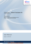
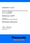
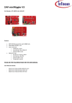
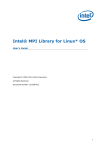
TDA7255V - UWLink© Evaluation Kit Universal Wireless Link TDA7255V ASK/FSK Transceiver for the 434 MHz frequency band User Manual Revision 1.0, 2010-12-01 Wireless Control Edition 2010-12-01 Published by Infineon Technologies AG 81726 Munich, Germany © 2010 Infineon Technologies AG All Rights Reserved. Legal Disclaimer The information given in this document shall in no event be regarded as a guarantee of conditions or characteristics. With respect to any examples or hints given herein, any typical values stated herein and/or any information regarding the application of the device, Infineon Technologies hereby disclaims any and all warranties and liabilities of any kind, including without limitation, warranties of non-infringement of intellectual property rights of any third party. Information For further information on technology, delivery terms and conditions and prices, please contact the nearest Infineon Technologies Office (www.infineon.com). Warnings Due to technical requirements, components may contain dangerous substances. For information on the types in question, please contact the nearest Infineon Technologies Office. Infineon Technologies components may be used in life-support devices or systems only with the express written approval of Infineon Technologies, if a failure of such components can reasonably be expected to cause the failure of that life-support device or system or to affect the safety or effectiveness of that device or system. Life support devices or systems are intended to be implanted in the human body or to support and/or maintain and sustain and/or protect human life. If they fail, it is reasonable to assume that the health of the user or other persons may be endangered. TDA7255V TDA7255V Revision History: 2010-12-01, 1.0 Previous Revision: none Page Subjects (major changes since last revision) initial version Trademarks of Infineon Technologies AG APOXI™, BlueMoon™, COMNEON™, CONVERGATE™, COSIC™, C166™, CROSSAVE™, CanPAK™, CIPOS™, CoolMOS™, CoolSET™, CORECONTROL™, DAVE™, EasyPIM™, EconoBRIDGE™, EconoDUAL™, EconoPACK™, EconoPIM™, EiceDRIVER™, EUPEC™, FCOS™, FALC™, GEMINAX™, GOLDMOS™, HITFET™, HybridPACK™, ISAC™, ISOFACE™, IsoPACK™, my-d™, MIPAQ™, ModSTACK™, NovalithIC™, OmniTune™, OmniVia™, OPTIVERSE™, OptiMOS™, ORIGA™, PROFET™, PRO-SIL™, PrimePACK™, RASIC™, ReverSave™, SCEPTRE™, SEROCCO™, SICOFI™, SMARTi™, SMINT™, SOCRATES™, SatRIC™, SensoNor™, SINDRION™, SmartLEWIS™, SIEGET™, TrueNTRY™, TEMPFET™, TriCore™, thinQ!™, TRENCHSTOP™, VINAX™, VINETIC™, X-GOLD™, XMM™, X-PMU™, XPOSYS™, XWAY™. Other Trademarks AMBA™, ARM™, MULTI-ICE™, PRIMECELL™, REALVIEW™, THUMB™ of ARM Limited, UK. AUTOSAR™ is licensed by AUTOSAR development partnership. Bluetooth™ of Bluetooth SIG Inc. CAT-iq™ of DECT Forum. COLOSSUS™, FirstGPS™ of Trimble Navigation Ltd. EMV™ of EMVCo, LLC (Visa Holdings Inc.). EPCOS™ of Epcos AG. FLEXGO™ of Microsoft Corporation. FlexRay™ is licensed by FlexRay Consortium. HYPERTERMINAL™ of Hilgraeve Incorporated. IEC™ of Commission Electrotechnique Internationale. IrDA™ of Infrared Data Association Corporation. ISO™ of INTERNATIONAL ORGANIZATION FOR STANDARDIZATION. MATLAB™ of MathWorks, Inc. MAXIM™ of Maxim Integrated Products, Inc. MICROTEC™, NUCLEUS™ of Mentor Graphics Corporation. Mifare™ of NXP. MIPI™ of MIPI Alliance, Inc. MIPS™ of MIPS Technologies, Inc., USA. muRata™ of MURATA MANUFACTURING CO. OmniVision™ of OmniVision Technologies, Inc. Openwave™ Openwave Systems Inc. RED HAT™ Red Hat, Inc. RFMD™ RF Micro Devices, Inc. SIRIUS™ of Sirius Sattelite Radio Inc. SOLARIS™ of Sun Microsystems, Inc. SPANSION™ of Spansion LLC Ltd. Symbian™ of Symbian Software Limited. TAIYO YUDEN™ of Taiyo Yuden Co. TEAKLITE™ of CEVA, Inc. TEKTRONIX™ of Tektronix Inc. TOKO™ of TOKO KABUSHIKI KAISHA TA. UNIX™ of X/Open Company Limited. VERILOG™, PALLADIUM™ of Cadence Design Systems, Inc. VLYNQ™ of Texas Instruments Incorporated. VXWORKS™, WIND RIVER™ of WIND RIVER SYSTEMS, INC. ZETEX™ of Diodes Zetex Limited. The information in this document is subject to change without notice. Last Trademarks Update 2009-05-27 Template: central_a4_template_20090126.dot / 3.00 / 2009-01-26 TDA7255V Table of Contents Table of Contents 1 Introduction ........................................................................................................................................ 6 2 Using the TDA7255V UWLink Extension-Board as stand-alone module ..................................... 7 3 Using the TDA7255V UWLink Extension-Board together with the UWLink Mainboard as interface to a Windows PC .......................................................................................................................................... 9 User Manual 4 Revision 1.0, 2010-12-01 TDA7255V List of Figures List of Figures Figure 1 Figure 2 Figure 3 Figure 4 Figure 5 Figure 6 Figure 7 Figure 8 Figure 9 Figure 10 Figure 11 Figure 12 Figure 13 Figure 14 Figure 15 Evaluation-Kit: 2 x TDA7255V UWLink Mainboard & Extension-Board............................................... 6 Jumper (axial)....................................................................................................................................... 7 Jumper (SMD) ...................................................................................................................................... 8 SIB-Server button.................................................................................................................................... 9 TDA7255V Explorer button..................................................................................................................... 10 TDA7255V-Explorer, Open button........................................................................................................... 11 TDA7255V-Explorer, Wizard tab ............................................................................................................. 11 RX/TX and ASK/FSK external controlled or register controlled ................................................................... 12 TDA7255V-Explorer, Register tab ........................................................................................................... 12 TDA7255V-Explorer, Explorer tab ........................................................................................................... 13 TDA7255V-Explorer, Explorer tab, Test transmission field ......................................................................... 13 TDA7255V-Explorer, Explorer tab, Power Down and Data Detect pin ........................................................ 14 Reset button ......................................................................................................................................... 14 Save button .......................................................................................................................................... 14 File-Open button ................................................................................................................................ 15 User Manual 5 Revision 1.0, 2010-12-01 TDA7255V Introduction 1 Introduction The TDA7255V UWLINK Extension-Board can either be used as stand-alone module with any other system environment or together with the UWLink Mainboard as Interface to your Windows PC. The TDA7255V-Explorer Windows Software may be used to set the configuration registers and to read out the status registers of the TDA7255V. Figure 1 Evaluation-Kit: 2 x TDA7255V UWLink Mainboard & Extension-Board User Manual 6 Revision 1.0, 2010-12-01 TDA7255V Using the TDA7255V UWLink Extension-Board as stand-alone module 2 Using the TDA7255V UWLink Extension-Board as stand-alone module Close solder bridge JP1 (see Figure 3; default setting of the TDA7255V UWLink Extension-Board). Leave solder bridge JP2, JP3, JP4 and JP5 open (see Figure 3; default setting of the TDA7255V UWLink ExtensionBoard). Select either RX-mode or TX-mode by setting the jumper of the RX/TX-multi-pin connector (X8) accordingly (see Figure 2). Select either ASK or FSK by setting the jumper of the ASK/FSK-multi-pin connector (X7) accordingly (see Figure 2). Apply a supply voltage of 3V (2.1V to 5V) to connector X3 (for polarity see also Figure 2). Apply an antenna or RF-signal generator on the 50 Ω RF-connector (X1; see Figure 2) if the RX-mode is selected (via RX/TX-Jumper). Use an ASK-modulated or FSK-modulated RF-signal according the mode selected by the jumper of the ASK/FSK-multi-pin connector. Apply an antenna or Spectrum-Analyzer to be able to measure the spectrum, for instance, on the 50 Ω RF-connector (X1; see Figure 2) if the TX-mode is selected (via RX/TX-Jumper). CAUTION: Applying a signal, from a RF-signal generator for instance, in TX-mode could possibly damage the power amplifier output of the TDA7255V! Connect the Data Input/Output (X2; see Figure 2) to an Oscilloscope, for instance, to be able to measure the data output signal, in case of RX-mode (via RX/TX-Jumper) is selected. Apply a data signal, a PRBS9-sequence or just a rectangular signal on the Data Input/Output (X2; see Figure 2) if TXmode is selected. For data signal Low- and High-level see the Data Sheet. Figure 2 Jumper (axial) User Manual 7 Revision 1.0, 2010-12-01 TDA7255V Using the TDA7255V UWLink Extension-Board as stand-alone module Name and function of the connectors and Jumpers of the TDA7255V UWLink Extension-Board: X1: 50 Ω RF-connector (RF-In in receive-mode/RF-Out in transmit-mode) X2: Data Input/Output X3: Supply-Connector (Vcc/GND) external supply X7: ASK/FSK-multi-pin connector X8: RX/TX- multi-pin connector X14: CLKDIV-Output-Connector (Clock-output) X15: PWDDD-Connector X16: RSSI-Output S1: Reset-switch JP1: Reset via Switch S1 JP2: Data to UWLink JP3: Reset via UWLink JP4: Supply via UWLink JP5: PWDDD via UWLINK Figure 3 Jumper (SMD) User Manual 8 Revision 1.0, 2010-12-01 TDA7255V Using the TDA7255V UWLink Extension-Board together with the UWLink Mainboard as interface to a Windows PC 3 Using the TDA7255V UWLink Extension-Board together with the UWLink Mainboard as interface to a Windows PC Before using the UWLink Mainboard as interface, the required software, which can be downloaded from the Infineon Web page (see link below), has to be installed. Please follow this step-by-step approach when you start up your TDA7255V-UWLink-Set for the first time: Important Note: The TDA7255V Explorer Windows Software requires the DAS (Device Access Server) and the SIBServer services running in the background. Both are automatically installed while following the steps below. Step 1 – Installation of the TDA7255V-Explorer Go to www.infineon.com/TDA7255V and download the latest TDA7255V-Explorer Installation Package (e.g. TDA7255V_Explorer_E1.1.05.zip) Extract the ZIP-archive to a temporary directory on your PC. Open the sub-directory 1_DAS and execute DAS_setup.exe and follow the on-screen instructions. Execute TDA7255V_Explorer_E1.1.05.exe and follow the on-screen instructions. Execute the NextGenLoader and start the installation of the SIB-Server by just double-clicking at the SIB Server button (see Figure 4) and follow the on-screen instructions. Figure 4 SIB-Server button Step 2 – Usage of the TDA7255V-Explorer Start the TDA7255V Explorer by double-clicking at the TDA7255V Explorer button (see Figure 5). Click to OPEN in the Wizard-tab to start the communication (see Figure 6). Now you are ready to configure the TDA7255V: Either by changing the settings in the Wizard-tab of the TDA7255V Explorer (see Figure 6), or by changing the bit values of each register directly in the Registers-tab (see Figure 9). CAUTION: If you choose RX/TX and ASK/FSK “Register Controlled” (see Figure 8) it is strongly recommend to remove the jumper of the RX/TX-multi-pin connector and ASK/FSK-multi-pin connector to avoid conflicting hardware and software settings and harming of the TDA7255V! User Manual 9 Revision 1.0, 2010-12-01 TDA7255V Using the TDA7255V UWLink Extension-Board together with the UWLink Mainboard as interface to a Windows PC Furthermore you can read the SFR Status register and SFR ADC register at the Explore-tab. See the RSSI Voltage and Vcc Measurement- and Data valid decision-fields in the Explore-tab (see Figure 10). A PRBS9 sequence with variable data rate can be generated by the TDA7255V-Explorer and will be applied to the data input when closing the jumper JP2 (see Figure 3). The desired data rate can be adjusted and the transmission started in the Test transmission-field in the Explore-tab (see also Figure 11). The TDA7255V can be switched between Power-Down-Mode and Device-Active-Mode by the TDA7255V-Explorer when closing the jumper JP5 (see Figure 3). You can switch to Power-Down-Mode or Device-Active-Mode by just clicking on the accordant side of the symbolic dip-switch in the Power Down and Data Detect pin-field in the Explore-tab (see Figure 12). The TDA7255V can be reset by the “Reset”-button in the Chip Control-field at each tab of the TDA7255V-Explorer (see Figure 13) when closing jumper JP3 and opening jumper JP1 (see Figure 3). The registers settings can be saved as config-file (*_spi.def) by clicking at the “Save”-button in the Register-tab on the one hand (see Figure 14). Already available config-files can loaded by clicking at the “File-Open”-button on the other hand (see Figure 15) Figure 5 TDA7255V Explorer button User Manual 10 Revision 1.0, 2010-12-01 TDA7255V Using the TDA7255V UWLink Extension-Board together with the UWLink Mainboard as interface to a Windows PC Figure 6 TDA7255V-Explorer, Open button Figure 7 TDA7255V-Explorer, Wizard tab User Manual 11 Revision 1.0, 2010-12-01 TDA7255V Using the TDA7255V UWLink Extension-Board together with the UWLink Mainboard as interface to a Windows PC Figure 8 RX/TX and ASK/FSK external controlled or register controlled Figure 9 TDA7255V-Explorer, Register tab User Manual 12 Revision 1.0, 2010-12-01 TDA7255V Using the TDA7255V UWLink Extension-Board together with the UWLink Mainboard as interface to a Windows PC Figure 10 TDA7255V-Explorer, Explorer tab Figure 11 TDA7255V-Explorer, Explorer tab, Test transmission field User Manual 13 Revision 1.0, 2010-12-01 TDA7255V Using the TDA7255V UWLink Extension-Board together with the UWLink Mainboard as interface to a Windows PC Figure 12 TDA7255V-Explorer, Explorer tab, Power Down and Data Detect pin Figure 13 Reset button Figure 14 Save button User Manual 14 Revision 1.0, 2010-12-01 TDA7255V Using the TDA7255V UWLink Extension-Board together with the UWLink Mainboard as interface to a Windows PC Figure 15 File-Open button Step 3 – Configure the TDA7255V UWLink Extension-Board by the TDA7255V-Explorer via the USB connector of the PC If “reset” via TDA7255V-Explorer is desired or required you have to close solder bridge JP3 and open JP1 (see Figure 3). If you intend to send the PRBS9 sequence of the TDA7255V-Explorer (see Test transmission-field in the Exploretab) in TX-mode you have to close solder bridge JP2 (see Figure 3). If you intend to supply the TDA7255V UWLink Extension-Board via the UWLink Mainboard you have to close JP4 (see Figure 3). If you intend to control the power-mode (Power-Down-Mode/Device-Active-Mode) of the TDA7255V by the TDA7255V-Explorer you have to close solder bridge JP5 (see Figure 3). Connect the TDA7255V UWLink Extension-Board to the UWLink Mainboard. The TDA7255V UWLink Extension-Board can be supplied by the USB-connector via the UWLink-Mainboard by closing jumper JP4 (see Figure 3). Alternatively, the TDA7255V UWLink Extension-Board may be supplied by an external power supply of 3V (2.1V to 5V) via connector X3 (JP4 must be open). For the polarity of X3 see also Figure 2. Connect the UWLink Mainboard to the USB-connector of your PC. Start the TDA7255V Explorer by double-clicking at the TDA7255V Explorer button (see Figure 5). Click to OPEN in the Wizard-tab to start the communication (see Figure 6). It is strongly recommended to remove the jumper of the RX/TX-multi-pin connector and ASK/FSK-multi-pin connector before you select “RX/TX and ASK/FSK Register Controlled” (see Figure 8) to avoid conflicting hardware and software settings and harming of the TDA7255V! If you select “RX/TX and ASK/FSK external controlled” (see Figure 8) you have to set the jumper of the ASK/FSK- and RX/TX-multi-pin connector according the desired mode (see Figure 2). User Manual 15 Revision 1.0, 2010-12-01 TDA7255V Using the TDA7255V UWLink Extension-Board together with the UWLink Mainboard as interface to a Windows PC Apply an antenna or RF-signal generator on the 50 Ω RF-connector (X1; see Figure 2) if the RX-mode is selected. Use an ASK-modulated or FSK-modulated RF-signal according the selected mode. Apply an antenna or Spectrum-Analyzer to be able to measure the spectrum, for instance, on the 50 Ω RF-connector (X1; see Figure 2) if the TX-mode is selected (via RX/TX-Jumper). CAUTION: Applying a signal, from a RF-signal generator for instance, in TX-mode could possibly damage the power amplifier output of the TDA7255V! Connect the Data Input/Output (X2; see Figure 2) to an Oscilloscope, for instance, to be able to measure the data signal, in case of RX-mode (via RX/TX-Jumper) is selected. Apply a data signal or just a rectangular signal on the Data Input/Output (X2; see Figure 2) if TX-mode is selected or use the PRBS9-sequence of the TDA7255V-Explorer when JP2 is closed. For data signal Low- and High-level see Data Sheet. User Manual 16 Revision 1.0, 2010-12-01 w w w . i n f i n e o n . c o m Published by Infineon Technologies AG