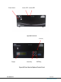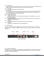
1
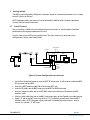
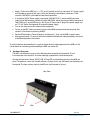
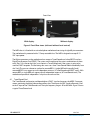
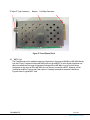
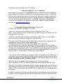
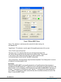
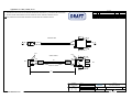
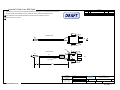
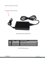
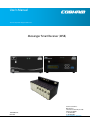
Apply +12Vdc to the MSR, pins 1 (+12 V) and 2 (ground) to the 2 pin connector (P1). Power supply must be able to source up to 6 amps (when also powering external down converters). Cable assembly 780-C0242 is provided to make these connections. If an optional AC/DC Power supply is purchased (GMS # 473-051), attach the XLR connector (male) to the XLR connector (female) of cable 780-C0234. Attach the two pin Molex connector of 780-C0234 to P1 of the MSR chassis. (Ref. Figure 3). Plug in the AC plug of the power supply into an 115 VAC Outlet. See Appendix D for optional power supply. Turn on the video source and video monitor equipment. To turn on the BDC (down converter) from the front MSR control panel at the computer. See section 6.3 for details on powering the BDC. Set the RF Bandwidth & Center Frequency and then push “Tune” on the MSR’s control screen. After approximately 2-5 seconds, the link should be established and video provided by the source should be displayed on the monitor. The initial checkout described above is simply to check the basic video operation of the MSR unit. For further details on monitoring and controlling the MSR, see section 6.3 4 Hardware Overview The MSR’s versatile housing can sit on a desktop or be mounted with the optional 19-inch instrumentation rack-mount kit. It can be optionally supplied with a local control panel. All interface connectors (Power, RS232, USB, ASI and SPI) are located on the rear of the MSR unit panel. The power on switch and two led indicators (System Active and ASI locked) are located on the front panel. The front and rear view of the MSR unit are illustrated in Figure 4. Rear View Slot 8 100-M0061X5C Slot 1 9 of 43 www.cobham.com/gms