1
5 Mounting/Dismantling
8 Technical data
The MELSEC-WS safety controller is only suitable for
mounting in a control cabinet with at least IP 54
ATTENTION degree of protection.
While supply voltage is applied, modules must not be
plugged to nor be removed from the MELSEC-WS
safety controller.
5.1 Mounting the modules
• In a MELSEC-WS safety controller, the WS0-CPU0 or WS0-CPU1 is
positioned at the far left and the two optional network modules follow
directly. Only then do the safety I/O modules follow. The WS0-4RO
module has to be mounted at the far right.
• The modules are located in a 22.5mm wide modular system for 35mm
DIN rails to IEC/EN 60715.
• The connection between the modules is effected by means of the plug
connection integrated in the housing.
• Mount the modules in accordance with EN 50274
• Ensure that suitable ESD protective measures are also taken during
mounting. Otherwise the FLEXBUS+ backplane bus may be damaged.
• Take suitable measures to ensure that foreign matter does not enter the
connector openings, in particular that of the memory plug.
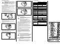
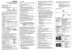
⇒ If there are several modules, slide the modules away from each other
individually in the direction of the arrow until the side plug connection is
separated.
⇒ Press the module downwards at the rear (1)) and remove it from the
DIN rail in the direction of the arrow while keeping it pressed down (2)).
6 Electrical installation
⇒ Make sure that the voltage supply of the MELSEC-WS safety controller
is switched off.
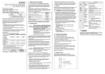
⇒ Hang the device onto the DIN rail (1)).
⇒ Ensure that the earthing spring contact is positioned correctly (2)). The
earthing spring contact of the module must contact the DIN rail
securely to allow electrical conductivity.
⇒ Snap the module onto the DIN rail by pressing it lightly in the direction
of the arrow (3)).
⇒ If there are several modules, slide the modules together individually in
the direction of the arrow until the side plug connection latches in.
⇒ Install the end clips on the left and right.
5.2 Steps for dismantling the modules
De-energize the entire system!
The system could start up unexpectedly while you are
ATTENTION connecting the devices.
Observe the relevant safety standards!
All safety related parts of the installation (cabling,
connected sensors and actuators, configuration settings,
EDM) must be according to the relevant safety standards
(e.g. IEC 62061 or EN/ISO 13849-1).
• The MELSEC-WS safety controller fulfils the EMC requirements in
accordance with the basic specification IEC 61000-6-2 for industrial use.
• Electrical installation in accordance with IEC 60204-1
• To ensure full electromagnetic compatibility (EMC), the DIN rail has to
be connected to functional earth (FE).
• The voltage supply of the devices must be capable of buffering brief
mains voltage failures of 20ms as specified in IEC 60204-1.
• The voltage supply has to fulfil the regulations for extra-low voltages with
safe separation (SELV, PELV) in accordance with IEC 60664 and EN
50178 (equipment of electrical power installation with electronic
devices).
• You must connect all the modules of the MELSEC-WS safety controller,
the connected protective devices as well as the voltage supply/ies with
the same 0VDC (GND).
• All connected pick-ups and downstream controllers as well as wiring
and installation have to fulfil the required safety characteristics.
• If a module is replaced the correct terminal assignment has to be
guaranteed, for example by labelling or suitable cable routing.
• For further information that is to be taken into consideration when the
MELSEC-WS safety controller is used, refer to the "Safety Controller
User’s Manual" and "Safety Controller Setting and Monitoring Tool
Operating Manual".
7 Configuration and commissioning
Do not commission without a check by qualified
safety personnel!
Before initial commissioning of a system using a
ATTENTION
MELSEC-WS safety controller, it must be checked and
released by qualified personnel. Document the result of
the safety check.
⇒ Remove the removable terminals with wiring and the end clips.
The MELSEC-WS safety controller can be configured by the Setting and
Monitoring Tool connected to the RS-232 interface of a CPU module or the
port of an Ethernet interface module.
Note • The Setting and Monitoring Tool version 1.3.0 or higher is
required to configure and commission the MELSEC-WS safety
controller.
• The system configuration of the complete MELSEC-WS safety
controller is stored in the memory plug. The system does not
have to be reconfigured when a module is replaced.
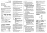
WS0-CPU0
WS0-CPU1
Safety Integrity Level
SIL3 (IEC 61508)
SIL claim limit
SILCL3 (IEC 62061)
Category
Category 4 (EN/ISO 13849-1)
Performance Level
PLe (EN/ISO 13849-1)
PFHd (mean probability
1.07 × 10⁻⁹
1.69 × 10⁻⁹
of a dangerous failure
per hour)
TM (mission time)
20 years (EN/ISO 13849-1)
Protection class
III (IEC 61140)
Terminals: IP20 (IEC 60529)
Enclosure rating
Housing: IP40 (IEC 60529)
Ambient temperature in
-25 ... +55°C
operation
Storage temperature
-25 ... +70°C
Humidity
10% ... 95%, non-condensing
55°C, 95% rel. humidity (IEC 61131-2),
Climatic conditions
No corrosive gases
Vibration resistance
10-500 Hz/5g (IEC 60068-2-6)
Shock resistance
Continuous shock
10g, 16ms (IEC 60068-2-29)
Single shock
30g, 11ms (IEC 60068-2-27)
Electromagnetic
Class A (IEC 61000-6-2, EN 55011)
compatibility
Number of EFI
0
2
interfaces
Data interface
Backplane bus (FLEXBUS+)
Configuration interface
RS-232
Single-core or finely stranded:
1 × 0.14 … 2.5 mm2 or 2 × 0.14 … 0.75mm2
Cross-section of
Finely stranded with wire end ferrules to EN
connecting wires
46228:
1 × 0.25 … 2.5mm2 or 2 × 0.25 … 0.5mm2
Dual level spring
EFI connection method –
clamp terminals
22.5 × 96.5 ×
22.5 × 101.7 ×
Dimensions
(W × H × D)
120.8mm
120.8mm
Weight
111g (+/- 5%)
119g (+/- 5%)
Power supply unit (A1, A2) via memory plug WS0-MPL
Supply voltage
Type of supply
voltage
Power consumption
Switch-on time
WS0-CPU0
WS0-CPU1
24VDC (16.8 ... 30VDC)
PELV or SELV
The current of the power supply unit that
supplies the CPU module has to be limited to a
maximum of 4A – either by the power supply
unit itself or by a fuse
Max. 2.5W
Max. 18s