1
1
Thank you for purchasing LS Variable Frequency Drives!
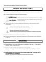
SAFETY INSTRUCTIONS
Always follow safety instructions to prevent accidents and potential hazards from occurring.
In this manual, safety messages are classified as follows:
WARNING
Improper operation may result in serious personal injury or death.
CAUTION
Improper operation may result in slight to medium personal injury
or property damage.
Throughout this manual we use the following two illustrations to make you aware of safety
considerations:
Identifies potential hazards under certain conditions.
Read the message and follow the instructions carefully.
Identifies shock hazards under certain conditions.
Particular attention should be directed because dangerous voltage may be present.
Keep operating instructions handy for quick reference.
Read this manual carefully to maximize the performance of SV-iG5A series inverter and ensure
its safe use.
WARNING
Do not remove the cover while power is applied or the unit is in operation.
Otherwise, electric shock could occur.
Do not run the inverter with the front cover removed.
Otherwise, you may get an electric shock due to high voltage terminals or charged capacitor
exposure.
Do not remove the cover except for periodic inspections or wiring, even if
the input power is not applied.
Otherwise, you may access the charged circuits and get an electric shock.
2
Wiring and periodic inspections should be performed at least 10 minutes
after disconnecting the input power and after checking the DC link voltage
is discharged with a meter (below DC 30V).
Otherwise, you may get an electric shock.
Operate the switches with dry hands.
Otherwise, you may get an electric shock.
Do not use the cable when its insulating tube is damaged.
Otherwise, you may get an electric shock.
Do not subject the cables to scratches, excessive stress, heavy loads or
pinching.
Otherwise, you may get an electric shock.
CAUTION
Install the inverter on a non-flammable surface. Do not place flammable
material nearby.
Otherwise, fire could occur.
Disconnect the input power if the inverter gets damaged.
Otherwise, it could result in a secondary accident and fire.
After the input power is applied or removed, the inverter will remain hot for
a couple of minutes.
Otherwise, you may get bodily injuries such as skin-burn or damage.
Do not apply power to a damaged inverter or to an inverter with parts
missing even if the installation is complete.
Otherwise, electric shock could occur.
Do not allow lint, paper, wood chips, dust, metallic chips or other foreign
matter into the drive.
Otherwise, fire or accident could occur.
3
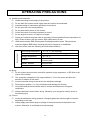
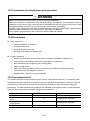
OPERATING PRECAUTIONS
Environment
(1) Handling and installation
Handle according to the weight of the product.
Do not stack the inverter boxes higher than the number recommended.
Install according to instructions specified in this manual.
Do not open the cover during delivery.
Do not place heavy items on the inverter.
Check the inverter mounting orientation is correct.
Do not drop the inverter, or subject it to impact.
Follow your national electrical code for grounding. Recommended Ground impedance for
200 V Class is below 100 ohm and for 400V class below 10 ohm.
iG5A series contains ESD (Electrostatic Discharge) sensitive parts. Take protective
measures against ESD before touching the pcb for inspection or installation.
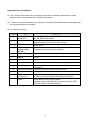
Use the inverter under the following environmental conditions:
Surrounding temperature
Relative humidity
Storage temperature
Location
Altitude, Vibration
Atmospheric pressure
- 10 ~ 50 ℃ (non-freezing)
90% RH or less (non-condensing)
- 20 ~ 65 ℃
Protected from corrosive gas, combustible gas,
oil mist or dust
Max. 1,000m above sea level, Max. 5.9m/sec2
(0.6G) or less
70 ~ 106 kPa
(2) Wiring
Do not connect a power factor correction capacitor, surge suppressor, or RFI filter to the
output of the inverter.
The connection orientation of the output cables U, V, W to the motor will affect the
direction of rotation of the motor.
Incorrect terminal wiring could result in the equipment damage.
Reversing the polarity (+/-) of the terminals could damage the inverter.
Only authorized personnel familiar with LS inverter should perform wiring and
inspections.
Always install the inverter before wiring. Otherwise, you may get an electric shock or
have bodily injury.
(3) Trial run
Check all parameters during operation. Changing parameter values might be required
depending on the load.
Always apply permissible range of voltage to the each terminal as indicated in this
manual. Otherwise, it could lead to inverter damage.
4
(4) Operation precautions
When the Auto restart function is selected, stay away from the equipment as a motor will
restart suddenly after an alarm stop.
The Stop key on the keypad is valid only when the appropriate function setting has been
made. Prepare an emergency stop switch separately.
If an alarm reset is made with the reference signal present, a sudden start will occur.
Check that the reference signal is turned off in advance. Otherwise an accident could
occur.
Do not modify or alter anything inside the inverter.
Motor might not be protected by electronic thermal function of inverter.
Do not use a magnetic contactor on the inverter input for frequent starting/stopping of the
inverter.
Use a noise filter to reduce the effect of electromagnetic interference. Otherwise nearby
electronic equipment may be affected.
In case of input voltage unbalance, install AC reactor. Power Factor capacitors and
generators may become overheated and damaged due to potential high frequency noise
transmitted from inverter.
Use an insulation-rectified motor or take measures to suppress the micro surge voltage
when driving 400V class motor with inverter. A micro surge voltage attributable to wiring
constant is generated at motor terminals, and may deteriorate insulation and damage
motor.
Before operating unit and prior to user programming, reset user parameters to default
settings.
Inverter can easily be set to high-speed operations, Verify capability of motor or
machinery prior to operating unit.
Stopping torque is not produced when using the DC-Break function. Install separate
equipment when stopping torque is needed.
(5) Fault prevention precautions
Provide a safety backup such as an emergency brake which will prevent the machine
and equipment from hazardous conditions if the inverter fails.
(6) Maintenance, inspection and parts replacement
Do not conduct a megger (insulation resistance) test on the control circuit of the inverter.
Refer to Chapter 12 for periodic inspection (parts replacement).
(7) Disposal
Handle the inverter as an industrial waste when disposing of it.
(8) General instructions
Many of the diagrams and drawings in this instruction manual show the inverter without a circuit
breaker, a cover or partially open. Never run the inverter like this. Always place the cover with
circuit breakers and follow this instruction manual when operating the inverter.
5
Important User Information
The purpose of this manual is to provide the user with the necessary information to install,
program, start up and maintain the SV-iG5A series inverter.
To assure successful installation and operation, the material presented must be thoroughly read
and understood before proceeding.
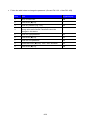
This manual contains…
Chapter
Title
1
Basic information &
precautions
2
Installation & Wiring
3
Basic configuration
4
Programming
keypad & Basic
operation
Function list
5
6
Description
Provides general information and precautions for safe use of
the SV-iG5A series inverter.
Provides instructions on how to install and wiring for power
source & signal terminal of SV-iG5A inverter.
Describes how to connect the optional peripheral devices to
the inverter.
Illustrates keypad features and display & Provides
instructions for quick start of the inverter.
Parameter values are listed.
7
Control block
diagram
Basic functions
Shows control flow to help users easily understand operation
mode.
Provides information for basic functions in the SV-iG5A
8
Advanced functions
Indicates advanced functions used for system application.
9
Monitoring
10
Protective functions
Gives information on the operating status and fault
information.
Outlines protective functions of the SV-iG5A.
11
RS 485
Provides specification of RS485 communication.
12
Troubleshooting &
maintenance
Specifications &
Option
Defines the various inverter faults and the appropriate action
to take as well as general troubleshooting information.
Gives information on Input/Output rating, control type and
more details of the SV-iG5A inverter.
Explains options including Remote keypad, Conduit, EMC
filter, DB resistor, DeviceNet Module.
13
6
Table of Contents
CHAPTER 1 -
Basic information & precautions ....................................................................... 1-1
1.1Important precautions .......................................................................................................... 1-1
1.2 Product Details.................................................................................................................... 1-2
1.3 Product assembling & disassembling .................................................................................. 1-3
CHAPTER 2 -
Installation & Wiring ........................................................................................... 2-1
2.1 Installation precautions ....................................................................................................... 2-1
2.2 Dimensions ......................................................................................................................... 2-3
2.3 Terminal wiring (Control I/O) ................................................................................................ 2-7
2.4 Specifications for power terminal block wiring ..................................................................... 2-9
2.5 Control terminal specification ............................................................................................ 2-12
2.6 PNP/NPN selection and connector for communication option ........................................... 2-13
CHAPTER 3 -
Basic configuration ............................................................................................ 3-1
3.1 Connection of peripheral devices to the inverter.................................................................. 3-1
3.2 Recommended MCCB ........................................................................................................ 3-2
3.3 Recommendable Fuse, Reactors ........................................................................................ 3-3
CHAPTER 4 -
Programming Keypad & Basic operation ......................................................... 4-4
4.1 Keypad features .................................................................................................................. 4-4
4.2 Alpha-numeric view on the LED keypad .............................................................................. 4-5
4.3 Moving to other groups ....................................................................................................... 4-6
4.4 How to change the codes in a group ................................................................................... 4-8
4.5 Parameter setting .............................................................................................................. 4-10
4.6 Monitoring of operation status ........................................................................................... 4-13
4.7 Frequency Setting and Basic Operation ............................................................................ 4-16
CHAPTER 5 -
Function list ........................................................................................................ 5-1
CHAPTER 6 -
CONTROL BLOCK DIAGRAM ............................................................................ 6-1
6.1 Frequency setting ............................................................................................................... 6-2
6.2 Drive command setting ....................................................................................................... 6-4
6.3 Accel/Decel setting and V/F control ..................................................................................... 6-5
CHAPTER 7 -
Basic Functions .................................................................................................. 7-1
7.1 Frequency mode ................................................................................................................. 7-1
7.2 Multi-Step Frequency setting ............................................................................................... 7-7
7.3 Operating command setting method ................................................................................... 7-8
7.4 Accel/Decel time and pattern setting ................................................................................. 7-12
7.5 V/F control ........................................................................................................................ 7-17
7.6 Stop method select ........................................................................................................... 7-20
7.7 Frequency limit.................................................................................................................. 7-21
CHAPTER 8 -
Advanced functions ........................................................................................... 8-1
8.1 DC brake............................................................................................................................. 8-1
8.2 Jog operation ...................................................................................................................... 8-3
8.3 UP-DOWN Drive ................................................................................................................. 8-4
7
8.4 3-Wire ................................................................................................................................. 8-7
8.5 Dwell operation ................................................................................................................... 8-7
8.6 Slip compensation ............................................................................................................... 8-8
8.7 PID control .......................................................................................................................... 8-9
8.8 Auto-tuning........................................................................................................................ 8-13
8.9 Sensorless Vector Control ................................................................................................. 8-14
8.10 Energy-saving operation ................................................................................................. 8-15
8.11 Speed search .................................................................................................................. 8-16
8.12 Auto restart try................................................................................................................. 8-18
8.13 Operating sound select (Carrier frequency change) ........................................................ 8-19
8.14 2nd motor operation ......................................................................................................... 8-19
8.15 Self-Diagnostic function .................................................................................................. 8-21
8.16 Frequency setting and 2nd drive method select ................................................................ 8-22
8.17 Over voltage trip prevention deceleration and Power Braking ......................................... 8-24
8.18 External brake control .................................................................................................... 8-24
8.19 Kinetic energy buffering................................................................................................... 8-26
8.20 DRAW drive ................................................................................................................... 8-26
8.21 2 Phase PWM drive ........................................................................................................ 8-28
8.22 Cooling fan control .......................................................................................................... 8-28
8.23 Operating mode select when cooling fan trip occurs ....................................................... 8-28
8.24 Parameter read/write....................................................................................................... 8-30
8.25 Parameter Initialize / Lock ............................................................................................... 8-31
CHAPTER 9 -
Monitoring ........................................................................................................... 9-1
9.1 Operating status monitoring ................................................................................................ 9-1
9.2 Monitoring the I/O terminal .................................................................................................. 9-3
9.3 Monitoring fault condition .................................................................................................... 9-4
9.4 Analog Output ..................................................................................................................... 9-6
9.5 Multi-function output terminal (MO) and Relay (3AC) .......................................................... 9-7
9.6 Output terminal select at loder communication error ......................................................... 9-12
CHAPTER 10 - Protective functions ......................................................................................... 10-1
10.1 Electronic Thermal .......................................................................................................... 10-1
10.2 Overload Warning and trip .............................................................................................. 10-2
10.3 Stall prevention ............................................................................................................... 10-3
10.4 Output phase loss protection ........................................................................................... 10-5
10.5 External trip signal........................................................................................................... 10-5
10.6 Inverter Overload ............................................................................................................ 10-6
10.7 Speed command loss ...................................................................................................... 10-6
10.8 DB Resistor Enable Duty setting ..................................................................................... 10-7
CHAPTER 11 - RS485 communication ..................................................................................... 11-1
11.1 Introduction ..................................................................................................................... 11-1
11.2 Specification .................................................................................................................... 11-1
11.3 Installation ....................................................................................................................... 11-2
8
11.4 Operation ........................................................................................................................ 11-2
11.5 Communication protocol (MODBUS-RTU)....................................................................... 11-3
11.6 Communication protocol (LS BUS) .................................................................................. 11-3
11.7 Parameter code list <Common area> (Note1) ................................................................ 11-6
11.8 Troubleshooting ............................................................................................................. 11-12
11.9 Miscellaneous ............................................................................................................... 11-12
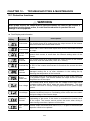
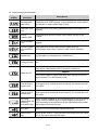
CHAPTER 12 - Troubleshooting & Maintenance ..................................................................... 12-1
12.1 Protective functions. ........................................................................................................ 12-1
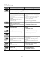
12.2 Fault remedy ................................................................................................................... 12-3
12.3 Precautions for maintenance and inspection ................................................................... 12-6
12.4Check points .................................................................................................................... 12-6
12.5 Part replacements ........................................................................................................... 12-6
CHAPTER 13 - Specifications ................................................................................................... 13-1
13.1 Technical data ................................................................................................................. 13-1
13.2 Temperature Derating Information ................................................................................... 13-4
13.3 Remote option................................................................................................................. 13-4
13.4 Conduit Kit ...................................................................................................................... 13-6
13.5 Braking resistor ............................................................................................................... 13-7
13.6 DeviceNet Communication Module ................................................................................. 13-8
DECLARATION OF CONFORMITY .................................................................................................... i
9
CHAPTER 1 - BASIC INFORMATION & PRECAUTIONS
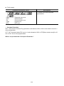
1.1Important precautions
Unpacking and
inspection
Inspect the inverter for any damage that may have occurred during shipping.
To verify the inverter unit is the correct one for the application you need,
check the inverter type, output ratings on the nameplate and the inverter is
intact.
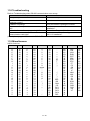
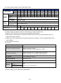
Inverter Type
Input power rating
Output Power Rating
Rated output current, frequency
Inverter Capacity (kVA)
Bar Code and Serial Number
SV
075
LS Inverter
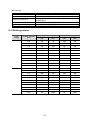
Motor rating
004
008
015
022
037
040
055
075
110
150
0.4 [kW]
0.75 [kW]
1.5 [kW]
2.2 [kW]
3.7 [kW]
4.0 [kW]
5.5 [kW]
7.5 [kW]
11.0[kW]
15.0[kW]
185
18.5[kW]
iG5A
-
Series
Name
iG5A
2
(N)
Input power
Keypad
1
Single Phase
200~230[V]
2
Three Phase
200~230[V]
4
Three Phase
380~480[V]
NON loader I/O
Products
220
22.0[kW]
Accessories
If you have found any discrepancy, damage, etc., contact your sales
representative.
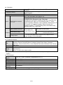
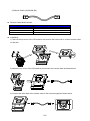
Preparations
of instruments
and parts
required for
operation
Instruments and parts to be prepared depend on how the inverter is operated.
Prepare equipment and parts as necessary.
Installation
To operate the inverter with high performance for a long time, install the inverter
in a proper place in the correct direction and with proper clearances
Wiring
Connect the power supply, motor and operation signals (control signals) to the
terminal block. Note that incorrect connection may damage the inverter and
peripheral devices
1-1
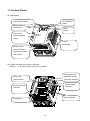
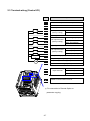
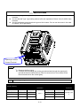
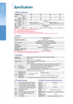
1.2 Product Details
Appearance
Status LED Display
STOP/RESET
button
RUN button
[ENT]
button
Front cover:
Removed when
wiring
Inverter
nameplate
Bottom cover:
Removed when
wiring input power
and a motor
Inside view after front cover is removed
Refer to “1.3 To remove the front cover” for details.
4-Way button for
NPN, PNP
parameter setting
Select Switch
(Up/Down/Left/Right)
Control signal
Inverter Ground
Terminal
Terminal
Power terminal
Cooling fan
1-2
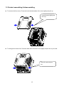
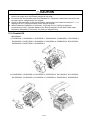
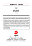
1.3 Product assembling & disassembling
To remove the front cover: Press the both indented sides of the cover lightly and pull up.
Press this part lightly and
pull it up.
To change the inverter fan: Press the both sides of bottom cover lightly and pull out to your side.
Press this part and pull
out.
1-3
Notes:
1-4
CHAPTER 2 - INSTALLATION & WIRING
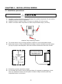
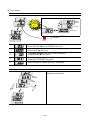
2.1 Installation precautions
CAUTION
Handle the inverter with care to prevent damage to the plastic components. Do not hold the
inverter by the front cover. It may fall off.
Install the inverter in a place where it is immune to vibration (5.9 m/s2 or less).
Install in a location where temperature is within the permissible range (-10~50C).
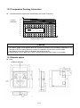
<Ambient Temp Checking Location>
The inverter will be very hot during operation. Install it on a non-combustible surface.
Mount the inverter on a flat, vertical and level surface. Inverter orientation must be vertical
(top up) for proper heat dissipation. Also leave sufficient clearances around the inverter.
10cm Min
5cm
5cm
Min
Min
Leave space enough to
allow cooled air flowing
easily between wiring
duct and the unit
10cm Min
Cooling air
Ventilating fan
Protect from moisture and direct sunlight.
Do not install the inverter in any environment where it is exposed to waterdrops, oil mist,
dust, etc. Install the inverter in a clean place or inside a “totally enclosed” panel any
suspended matter is not entered.
2-1
When two or more inverters are installed or a cooling fan is mounted in a panel, the inverters
and fan must be installed in proper positions with extreme care to keep the ambient
temperature below the permissible range.
Installed the inverter using screws or bolts to insure the inverter is firmly fastened.
< For installing multiple inverters in a panel>
Heat (NG)
CAUTION
Take caution on proper heat ventilation when installing inverters and fans in a panel.
2-2
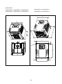
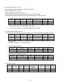
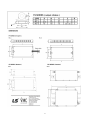
2.2 Dimensions
SV004iG5A-1
SV004iG5A-2 / SV008iG5A-2
SV008iG5A-1
SV004iG5A-4 / SV008iG5A-4
SV015iG5A-2 / SV015iG5A-4
2-3
SV015iG5A-1
SV022iG5A-2 / SV037iG5A-2 / SV040iG5A-2
SV055iG5A-2 / SV075iG5A-2
SV022iG5A-4 / SV037iG5A-4 / SV040iG5A-4
SV055iG5A-4 / SV075iG5A-4
W
H
D
A
W1
A
Φ
H1
B
B
W1
2-4
SV110iG5A-2 /SV150iG5A-2
SV185iG5A-2 / SV220iG5A-2
SV110iG5A-4 / SV150iG5A-4
SV185iG5A-4 / SV220iG5A-4
W
W
H
H
D
D
Φ
Φ
A
A
H1
H1
B
B
W1
B
B
W1
2-5
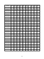
Inverter
[kW]
W
[mm]
W1
[mm]
H
[mm]
H1
[mm]
D
[mm]
Φ
A
[mm]
B
[mm]
[Kg]
SV004iG5A-1
0.4
70
65.5
128
119
130
4.0
4.5
4.0
0.76
SV008iG5A-1
0.75
100
95.5
128
120
130
4.5
4.5
4.5
1.12
SV015iG5A-1
1.5
140
132
128
120.5
155
4.5
4.5
4.5
1.84
SV004iG5A-2
0.4
70
65.5
128
119
130
4.0
4.5
4.0
0.76
SV008iG5A-2
0.75
70
65.5
128
119
130
4.0
4.5
4.0
0.77
SV015iG5A-2
1.5
100
95.5
128
120
130
4.5
4.5
4.5
1.12
SV022iG5A-2
2.2
140
132
128
120.5
155
4.5
4.5
4.5
1.84
SV037iG5A-2
3.7
140
132
128
120.5
155
4.5
4.5
4.5
1.89
SV040iG5A-2
4.0
140
132
128
120.5
155
4.5
4.5
4.5
1.89
SV055iG5A-2
5.5
180
170
220
210
170
4.5
5.0
4.5
3.66
SV075iG5A-2
7.5
180
170
220
210
170
4.5
5.0
4.5
3.66
SV110iG5A-2
11.0
235
219
320
304
189.5
7.0
8.0
7.0
9.00
SV150iG5A-2
15.0
235
219
320
304
189.5
7.0
8.0
7.0
9.00
SV185iG5A-2
18.5
260
240
410
392
208.5
10.0
10.0
10.0
13.3
SV220iG5A-2
22.0
260
240
410
392
208.5
10.0
10.0
10.0
13.3
SV004iG5A-4
0.4
70
65.5
128
119
130
4.0
4.5
4.0
0.76
SV008iG5A-4
0.75
70
65.5
128
119
130
4.0
4.5
4.0
0.77
SV015iG5A-4
1.5
100
95.5
128
120
130
4.5
4.5
4.5
1.12
SV022iG5A-4
2.2
140
132
128
120.5
155
4.5
4.5
4.5
1.84
SV037iG5A-4
3.7
140
132
128
120.5
155
4.5
4.5
4.5
1.89
SV040iG5A-4
4.0
140
132
128
120.5
155
4.5
4.5
4.5
1.89
SV055iG5A-4
5.5
180
170
220
210
170
4.5
5.0
4.5
3.66
SV075iG5A-4
7.5
180
170
220
210
170
4.5
5.0
4.5
3.66
SV110iG5A-4
11.0
235
219
320
304
189.5
7.0
8.0
7.0
9.00
SV150iG5A-4
15.0
235
219
320
304
189.5
7.0
8.0
7.0
9.00
SV185iG5A-4
18.5
260
240
410
392
208.5
10.0
10.0
10.0
13.3
SV220iG5A-4
22.0
260
240
410
392
208.5
10.0
10.0
10.0
13.3
2-6
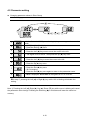
2.3 Terminal wiring (Control I/O)
T/M
Description
MO
Multi-function open collector output
MG
MO Common
24
24V output
P1
MF input terminal
FX: Forward run
P2
(factory setting)
RX: Reverse run
CM
Input signal common
P3
MF input terminal
P4
(factory setting)
P5
CM
MF input terminal
(factory setting)
P8
RST: Trip reset
JOG: Jog operation
Input signal common
P6
P7
BX: Emergency stop
Multi-step freq.-Low
Multi-step freq.-Middle
Multi-step freq.-High
VR
10V power supply for potentiometer
V1
Freq. Setting Voltage signal input: -0~10V
I
Freq. Setting Current signal input: 0~20mA
AM
Multi-function analog output signal: 0~10V
3A
Multi-function relay
A contact output
3B
output terminal
B contact output
3C
S+
S-
A/B contact common
RS485 communication terminal
※ For connection to Remote Option or
parameter copying
2-7
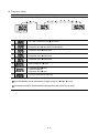
* Power terminal wiring (0.4 ~ 7.5kW)
3 Phase AC
input
(Input rated
voltage)
R
S
Power
input
terminal
B1
DB resistor
B2
DB
Resistor
connecti
on
terminal
U
Motor
B1
B2
T
V
Motor
connecti
on
terminal
R
U
S
V
T
W
G
G
W
G
Ground
terminal
※ AC input of Single Phase Products must be applied in R, T(0.4~1.5kW)
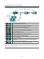
* Power terminal wiring (11.0 ~ 22.0kW)
3 phase AC
input
(Input rated
voltage)
DC reactor
R(L1)
S(L2)
P1
B1
(+)
T(L3)
P1(+)
B1
DB resistor
Power
input
terminal
B2
N(-)
Reactor
/ DB
Resistor
connection
terminal
(-) DC voltage
terminal
U
Motor
V
Motor
connection
terminal
R
(L1)
U
S
(L2)
V
T
(L3)
W
G
N(-)
W
G
B2
Ground
terminal
2-8
G
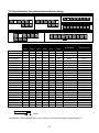
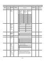
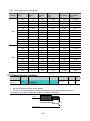
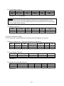
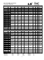
2.4 Specifications for power terminal block wiring
0.4 ~ 0.75kW(Single Phase)
0.4 ~ 1.5kW(Three Phase)
1.5kW(Single Phase)
R
R
T
B1 B2
R
S
T
T
B1 B2 U
V
W
B1 B2
2.2 ~ 4.0kW(Three Phase)
U
V
U
W
V
W
R
5.5 ~ 7.5kW(Three Phase)
B1
R
B2 U
S
V
S
T
B1 B2 U
V
W
11.0 ~ 22.0kW(Three Phase)
W
R
S
T
(L1)
(L2)
(L3)
P1 B1 B2 N
(+)
(-)
U
V
W
T
R,S,T Size
mm
2
AWG
U,V,W Size
mm
2
AWG
Ground Size
mm
2
AWG
Terminal
Screw Size
Screw Torque
(Kgf.cm)/lb-in
SV004iG5A-1
2
14
2
14
3.5
12
M3.5
10/8.7
SV008iG5A-1
2
14
2
14
3.5
12
M3.5
10/8.7
SV015iG5A-1
2
14
2
14
3.5
12
M4
15/13
SV004iG5A-2
2
14
2
14
3.5
12
M3.5
10/8.7
SV008iG5A-2
2
14
2
14
3.5
12
M3.5
10/8.7
SV015iG5A-2
2
14
2
14
3.5
12
M3.5
10/8.7
SV022iG5A-2
2
14
2
14
3.5
12
M4
15/13
SV037iG5A-2
3.5
12
3.5
12
3.5
12
M4
15/13
SV040iG5A-2
3.5
12
3.5
12
3.5
12
M4
15/13
SV055iG5A-2
5.5
10
5.5
10
5.5
10
M5
32/28
SV075iG5A-2
8
8
8
8
5.5
10
M5
32/28
SV110iG5A-2
14
6
14
6
14
6
M6
30.7/26.6
SV150iG5A-2
22
4
22
4
14
6
M6
30.7/26.6
SV185iG5A-2
30
2
30
2
22
4
M8
30.6/26.5
SV220iG5A-2
38
2
30
2
22
4
M8
30.6/26.5
SV004iG5A-4
2
14
2
14
2
14
M3.5
10/8.7
SV008iG5A-4
2
14
2
14
2
14
M3.5
10/8.7
SV015iG5A-4
2
14
2
14
2
14
M4
15/13
SV022iG5A-4
2
14
2
14
2
14
M4
15/13
SV037iG5A-4
2
14
2
14
2
14
M4
15/13
SV040iG5A-4
2
14
2
14
2
14
M4
15/13
SV055iG5A-4
3.5
12
2
14
3.5
12
M5
32/28
SV075iG5A-4
3.5
12
3.5
12
3.5
12
M5
32/28
SV110iG5A-4
5.5
10
5.5
10
8
8
M5
30.7/26.6
SV150iG5A-4
14
6
8
8
8
8
M5
30.7/26.6
SV185iG5A-4
14
6
8
8
14
6
M6
30.6/26.5
SV220iG5A-4
22
4
14
6
14
6
M6
30.6/26.5
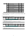
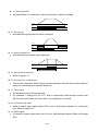
* Strip the sheaths of the wire insulation 7mm when a ring terminal is not used for power connection.
7.0mm
*SV185iG5A-2 and SV220iG5A-2 must use Ring or Fork Terminal certainly approved by UL.
2-9
CAUTION
Apply the rated torque to terminal screws. Loosen screws can cause of short circuit and
malfunction. Tightening the screw too much can damage the terminals and cause short
circuit and malfunction.
Use copper wires only with 600V, 75℃ ratings for wiring.
Make sure the input power is off before wiring.
When power supply is switched off following operation, wait at least 10 minutes after LED
keypad display is off before you start working on it.
Applying input power supply to the output terminals U, V and W causes internal inverter
damage.
Use ring terminals with insulated caps when wiring the input power and motor wiring.
Do not leave wire fragments inside the inverter. Wire fragments can cause faults,
breakdowns and malfunctions.
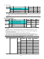
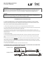
When more than one motor is connected to one inverter, total wire length should be less
than 200m (656ft). Do not use a 3-wire cable for long distances. Due to increased leakage
capacitance between wires, over-current protective feature may operate or equipment
connected to the output side may malfunction. In case of long wire length, it should be
required to lower carrier frequency or use Micro Surge Filter.
Length between Inverter and Motor
Allowable Carrier Frequency
Up to 50m
Up to 100m
More than 100m
Less than 15kHz
Less than 5kHz
Less than 2.5kHz
(For products of less than 3.7kW, the wire length should be less than 100m(328ft)).
Never short B1 and B2 terminals. Shorting terminals may cause internal inverter damage.
Do not install a power factor capacitor, surge suppressor or RFI filters in the output side of
the inverter. Doing so may damage these components.
[WARNING]
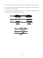
Power supply must be connected to the R, S, and T Terminals.
Connecting it to the U, V, W terminals causes internal damages to the inverter. Arranging the
phase sequence is not necessary.
Motor should be connected to the U, V, and W Terminals.
If the forward command (FX) is on, the motor should rotate counter clockwise when viewed from
the load side of the motor. If the motor rotates in the reverse, switch the U and V terminals.
2-10
WARNING
Use the Type 3 grounding method (Ground impedance: Below 100) for 230V class
inverters.
Use the Special Type 3 grounding method (Ground impedance: Below 10) for 460V class
inverters.
Use the dedicated ground terminal to ground the inverter. Do not use the screw in the case
or chassis, etc for grounding.
Opening to access
Ground Terminal
Note
Grounding procedure
1) Remove the front cover.
2) Connect the Grounding wire to the ground terminal through the opening for
ground terminal as shown above. Enter the screw driver from vertical to the
terminal and secure the screw tightly.
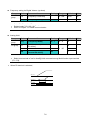
Note Grounding work guidance
200V Class
Inverter capacity
Wire size
Terminal screw
0.4~4.0 kW
3.5 mm2
M3
5.5~7.5 kW
5.5 mm2
M4
11 ~ 15 kW
14.0 mm2
M5
18.5~22 kW
22.0 mm2
M6
400V Class
Ground
Specification
Type 3
2-11
Wire size
Terminal screw
2.0 mm2
M3
3.5 mm2
M4
8.0 mm2
M5
14.0 mm2
M5
Ground
Specification
Special Type
3
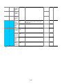
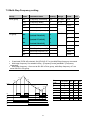
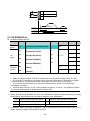
2.5 Control terminal specification
MO
3A
3B
MG
24
P1
P2
CM
P3
P4
P5
CM
P6
P7
P8
VR
V1
3C
S-
I
S+
AM
2
Wire size[mm ]
single
Stranded
wire
Screw
size
Torque
[Nm]
T/M
Terminal Description
P1~P8
CM
Multi-function input T/M 1-8
Common Terminal
1.0
1.0
1.5
1.5
M2.6
M2.6
0.4
0.4
VR
Power supply for external
potentiometer
1.0
1.5
M2.6
0.4
V1
Input terminal for Voltage
operation
Input terminal for Current
operation
1.0
1.5
M2.6
0.4
1.0
1.5
M2.6
0.4
AM
Multi-function analog output 1.0
terminal
1.5
M2.6
0.4
MO
Multi-function terminal for
open collector
Ground terminal for
external power supply
24V External Power Supply
1.0
1.5
M2.6
0.4
1.0
1.5
M2.6
0.4
1.0
1.5
M2.6
0.4
Multi-function relay output A 1.0
contact
Multi-function relay output
1.0
B contact
Common for Multi-function 1.0
relays
1.5
M2.6
0.4
Max output current:
100mA
Below AC 250V, 1A
1.5
M2.6
0.4
Below DC 30V, 1A
1.5
M2.6
0.4
I
MG
24
3A
3B
3C
Specification
Output voltage: 12V
Max output current:
100mA
Potentiometer:1 ~ 5kohm
Max input voltage:
-10V ~ +10V input
0 ~ 20mA input
Internal resistor: 250
ohm
Max output voltage: 11[V]
Max output current:
10mA
Below DC 26V,100mA
Note 1) Tie the control wires more than 15cm away from the control terminals. Otherwise, it interferes
front cover reinstallation.
Note 2) Use Copper wires rated 600V, 75 ℃ and higher.
Note 3) Use the recommended tightening torque when securing terminal screws.
Note
When you use external power supply (24V) for multi-function input terminal (P1~P8), terminals will
be active above 12V level. Take caution not to drop the voltage below 12V.
2-12
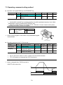
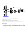
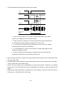
2.6 PNP/NPN selection and connector for communication option
1. When using DC 24V inside inverter [NPN]
SW S8
NPN
S8
DC 24 V
SW S8
CM
R
P1
CPU
R
R
CM
(inside inverter)
CM
2. When using external DC 24V [PNP]
SW S8
PNP
S8
DC 24 V
DC24V
CM
R
P1
R
CPU
R
CM
2-13
(inside inverter)
CM
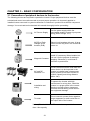
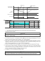
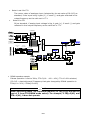
CHAPTER 3 - BASIC CONFIGURATION
3.1 Connection of peripheral devices to the inverter
The following devices are required to operate the inverter. Proper peripheral devices must be
selected and correct connections made to ensure proper operation. An incorrectly applied or
installed inverter can result in system malfunction or reduction in product life as well as component
damage. You must read and understand this manual thoroughly before proceeding.
AC Source Supply
Use the power supply within the
permissible range of inverter input power
rating (Refer to Page 13-1).
MCCB or Earth
leakage circuit
breaker (ELB)
Select circuit breakers with care. A large
inrush current may flow in the inverter at
power on.
Magnetic Contactor
Install it if necessary. When installed, do
not use it for the purpose of starting or
stopping. Otherwise, it could lead to
reduction in product life.
AC and DC
Reactors notice1
The AC reactors must be used when the
power factor is to be improved or the
inverter is installed near a large power
supply system (more than 10 times of
inverter capacity and wiring distance
within 10m).
Installation and
wiring
To operate the inverter with high
performance for a long time, install the
inverter in a proper place in the correct
direction and with proper clearances.
Incorrect terminal wiring could result in
the equipment damage.
To motor
Do not connect a power factor capacitor,
surge suppressor or radio noise filter to
the output side of the inverter.
Notice1) Terminal block for DC reactor is composed in the more
than 11kw capacity
3-1
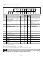
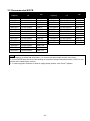
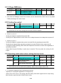
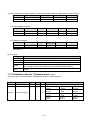
3.2 Recommended MCCB
Inverter
Capacity
MCCB
LS
Inverter
Capacity
MC
004iG5A-1
008iG5A-1
015iG5A-1
004iG5A-2
008iG5A-2
015iG5A-2
022iG5A-2
037iG5A-2
040iG5A-2
055iG5A-2
075iG5A-2
110iG5A-2
TD125U,EBs33
TD125U,EBs33
TD125U,EBs33
TD125U,EBs33
TD125U,EBs33
TD125U,EBs33
TD125U,EBs33
TD125U,EBs33
TD125U,EBs33
TD125U,EBs53
TD125U,EBs53
TD125U,EBs53
GMC-9
GMC-9
GMC-12
GMC-9
GMC-9
GMC-12
GMC-18
GMC-32
GMC-32
GMC-40
GMC-50
GMC-65
150iG5A-2
TD125U,EBs53
GMC-100
185iG5A-2
TS250U,EBs53
GMC-100
220iG5A-2
TS250U,EBs53
GMC-125
004iG5A-4
008iG5A-4
015iG5A-4
022iG5A-4
037iG5A-4
040iG5A-4
055iG5A-4
075iG5A-4
110iG5A-4
150iG5A-4
185iG5A-4
220iG5A-4
MCCB
LS
TD125U,EBs33
TD125U,EBs33
TD125U,EBs33
TD125U,EBs33
TD125U,EBs33
TD125U,EBs33
TD125U,EBs33
TD125U,EBs33
TD125U,EBs53
TD125U,EBs53
TD125U,EBs53
TD125U,EBs53
MC
GMC-9
GMC-9
GMC-9
GMC-12
GMC-18
GMC-22
GMC-32
GMC-32
GMC-40
GMC-50
GMC-65
GMC-65
Note
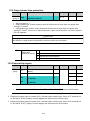
1. The capacity of the MCCB should be 1.5 to 2 times the rated output current of the drive.
2. Use an MCCB keep the drive from faulting out instead of using overheat protection (150% for one
minute at the rated output current.)
3. In case magnetic contactor is used on single-phase product, wire R and T phases.
3-2
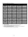
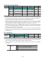
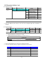
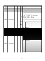
3.3 Recommendable Fuse, Reactors
Inverter Capacity
004iG5A-1
008iG5A-1
015iG5A-1
004iG5A-2
008iG5A-2
015iG5A-2
022iG5A-2
037iG5A-2
040iG5A-2
055iG5A-2
075iG5A-2
110iG5A-2
150iG5A-2
185iG5A-2
220iG5A-2
004iG5A-4
008iG5A-4
015iG5A-4
022iG5A-4
037iG5A-4
040iG5A-4
055iG5A-4
075iG5A-4
110iG5A-4
150iG5A-4
185iG5A-4
220iG5A-4
AC Input fuse [External Fuse]
Current
Voltage
10 A
600 V
10 A
600 V
15 A
600 V
10 A
600 V
10 A
600 V
15 A
600 V
25 A
600 V
30 A
600 V
30 A
600 V
30 A
600 V
50 A
600 V
70 A
600 V
100 A
600 V
100 A
600 V
125 A
600 V
5A
600 V
10 A
600 V
10 A
600 V
10 A
600 V
20 A
600 V
20 A
600 V
20 A
600 V
30 A
600 V
35 A
600 V
45 A
600 V
60 A
600 V
70 A
600 V
AC Reactor
DC Reactor
4.20 mH, 3.5A
2.13 mH, 5.7A
1.20 mH, 10A
4.20 mH, 3.5A
2.13 mH, 5.7A
1.20 mH, 10A
0.88 mH, 14A
0.56 mH, 20A
0.56 mH, 20A
0.39 mH, 30A
0.28 mH, 40A
0.20 mH, 59 A
0.15 mH, 75 A
0.12 mH, 96 A
0.10 mH, 112 A
18.0 mH, 1.3A
8.63 mH, 2.8A
4.81 mH, 4.8A
3.23 mH, 7.5A
2.34 mH, 10A
2.34 mH, 10A
1.22 mH, 15A
1.14 mH, 20A
0.81 mH, 30 A
0.61 mH, 38 A
0.45 mH, 50 A
0.39 mH, 58 A
-
0.74 mH, 56 A
0.57 mH, 71 A
0.49 mH, 91 A
0.42mH, 107 A
2.76 mH, 29 A
2.18 mH, 36 A
1.79 mH, 48 A
1.54 mH, 55 A
Short Circuit Rating
“Suitable For Use ON A Circuit Capable Of Delivering Not More Than 65KA
Symmetrical Amperes. 240V drives or 480V drives Volts Maximum,”
Short Circuit FUSE/BREAKER Marking
Use Class H or RK5 UL Listed Input Fuse and UL Listed Breaker Only. See the table above
For the Voltage and Current rating of the fuse and the breaker
3-3
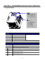
CHAPTER 4 - PROGRAMMING KEYPAD & BASIC OPERATION
4.1 Keypad features
Display
SET/RUN LED
FWD/REV LED
7 Segment LED
Key
RUN
STOP/RESET
Up/Down
Left/Right
Enter [ENT]
Display
FWD
Lit during forward run
Blinks when a fault occurs
REV
Lit during reverse run
RUN
Lit during Operation
SET
Lit during parameter setting
7 segment
Displays operation status and parameter information
Keys
RUN
Run command
STOP/RESET
UP
STOP: Stop command during operation,
RESET: Reset command when fault occurs.
Used to scroll through codes or increase parameter value
Down
Used to scroll through codes or decrease parameter value
Left
Right
ENT
Used to jump to other parameter groups or move a cursor to the left to
change the parameter value
Used to jump to other parameter groups or move cursor to the right to
change the parameter value
Used to set the parameter value or save the changed parameter value
4-4
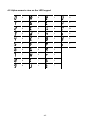
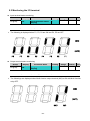
4.2 Alpha-numeric view on the LED keypad
0
A
K
U
1
B
L
V
2
C
M
W
3
D
N
X
4
E
O
Y
5
F
P
Z
6
G
Q
7
H
R
8
I
S
9
J
T
4-5
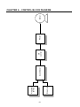
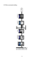
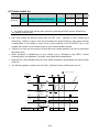
4.3 Moving to other groups
There are 4 different parameter groups in SV- iG5A series as shown below.
Drive group
FU group 1
FU group 2
I/O group
Drive group
Basic parameters necessary for the inverter to run. Parameters
such as Target frequency, Accel/Decel time settable.
Basic function parameters to adjust output frequency and
voltage.
Advanced function parameters to set parameters for such as
PID Operation and second motor operation.
Parameters necessary to make up a sequence using Multifunction input/output terminal.
Function group 1
Function group 2
I/O (Input/Output)
group
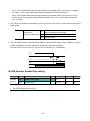
Moving to other parameter groups is only available in the first code of each group as the
figure shown below.
Moving to other groups using the Right ()
key
Moving to other groups using the Left () key
*
*
Drive group
Drive group
Function
group 1
I/O group
Function
group 1
I/O group
Function
group 2
Function
group 2
st
* Target frequency can be set at 0.0 (the 1 code of drive group). Even though the preset value is 0.0, it is
user-settable. The changed frequency will be displayed after it is changed.
4-6
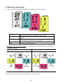
How to move to other groups at the 1st code of each group
-. The 1st code in Drive group “0.00” will be displayed when AC input
power is applied.
1
-. Press the right arrow () key once to go to Function group 1.
-. The 1st code in Function group 1 “F 0” will be displayed.
2
-. Press the right arrow () key once to go to Function group 2.
3
-. The 1st code in Function group 2 “H 0” will be displayed.
-. Press the right arrow () key once to go to I/O group.
4
-. The 1st code in I/O group “I 0” will be displayed.
-. Press the right arrow () key once again to return to Drive group.
5
-. Return to the 1st code in Drive group “0.00”.
If the left arrow key () is used, the above will be executed in the reverse order.
How to move to other groups from any codes other than the 1st code
Pressing left or
right arrow key in
any code will
return to first
code of each
group.
Drive group
FU group 2
FU group 1
To move from the F 15 to function group 2
1
-. In F 15, press the Left () or Right arrow () key. Pressing the key goes to
the first code of the group.
2
-. The 1st code in function group 1 “F 0” is displayed.
-. Press the right arrow () key.
3
-. The 1st code in function group 2 “H 0” will be displayed.
4-7
4.4 How to change the codes in a group
Code change in Drive group
-. In the 1st code in Drive group “0.00”,
press the Up () key once.
1
-. The 2nd code in Drive group “ACC” is
displayed.
-. Press the Up () key once.
-. The 3rd code “dEC” in Drive group is
displayed.
-. Keep pressing the Up () key until the
last code appears.
2
3
Drive group
4
-. The last code in Drive group “drC” is
displayed.
-. Press the Up () key again.
5
-. Return to the first code of Drive group.
Use Down () key for the opposite order.
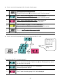
Code jump
When moving from the “F 0” to the “F 15” directly
1
-. Press the Ent () key in “F 0”.
2
-. 1 (the code number of F1) is displayed.
Use the Up () key to set to 5.
-. “05” is displayed by pressing the Left
() key once to move the cursor to the
left. The numeral having a cursor is
displayed brighter. In this case, 0 is active.
-. Use the Up () key to set to 1.
-. 15 is set.
-. Press the Ent () key once.
3
FU group 1
4
5
-. Moving to F 15 has been complete.
Function group 2 and I/O group are settable with the same setting.
4-8
Navigating codes in a group
When moving from F 1 to F 15 in Function group 1
1
-. In F 1, continue pressing the Up ()
key until F15 is displayed.
2
-. Moving to F15 has been complete.
The same applies to Function group 2 and I/O group.
Note: Some codes will be skipped in the middle of increment ()/decrement () for code
change. That is because it is programmed that some codes are intentionally left blank for
future use or the codes user does not use are invisible.
Refer to the Ch.5 for more specific contents
For example, when F24 [High/low frequency limit select] is set to “O (No) ”, F25 [High
frequency limit] and F26 [Low frequency limit] are not displayed during code change. But
When F24 is set to “1(Yes)”, F25 and F26 will appear on the display.
4-9
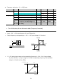
4.5 Parameter setting
Changing parameter values in Drive Group
When changing ACC time from 5.0 sec to 16.0 sec
Drive group
1
2
3
4
5
6
7
8
-. In the first code “0.00”, press the Up () key once to go to the second
code.
-. ACC [Accel time] is displayed.
-. Press the Ent key () once.
-. Preset value is 5.0, and the cursor is in the digit 0.
-. Press the Left () key once to move the cursor to the left.
-. The digit 5 in 5.0 is active. Then press the Up () key once.
-. The value is increased to 6.0
-. Press the Left () key to move the cursor to the left.
-. 0.60 is displayed. The first 0 in 0.60 is active.
-. Press the Up () key once.
-. 16.0 is set.
-. Press the Ent () key once.
-. 16.0 is blinking.
-. Press the Ent () key once again to return to the parameter name.
-. ACC is displayed. Accel time is changed from 5.0 to 16.0 sec.
♣ In step 7, pressing the Left () or Right () key while 16.0 is blinking will disable the
setting.
Note 1) Pressing the Left ()/ Right () /Up () /Down () key while cursor is blinking will cancel
the parameter value change. Pressing the Enter key () in this status will enter the value into
memory.
4-10
Frequency setting
When changing run frequency to 30.05 Hz in Drive group
Drive group
1
-. In “0.00”, press the Ent () key once.
2
-. The second decimal 0 becomes active.
-. Press the UP () key until 5 is displayed.
3
-. Press the Left () key once.
4
-. The first decimal 0 becomes active.
-. Press the Left () key once.
5
-. Press the Left () key once.
6
-. Set 3 using UP () key.
7
-. Press the Ent () key.
-. 30.05 is blinking.
-. Press the Ent () key.
8
-. 30.05 is entered into memory.
SV-iG5A display can be extended to 5 digits using left ()/right () keys.
Parameter setting is disabled when pressing other than Enter Key in step 7.
4-11
Changing parameter value in Input/Output group
When changing the parameter value of F28 from 2 to 5
FU group 1
1
-. In F0, press the Ent () key once.
2
-. Check the present code number.
-. Increase the value to 8 by pressing the Up () key.
3
-. When 8 is set, press the Left () key once.
4
5
6
7
-. 0 in 08 is active.
-. Increase the value to 2 by pressing the Up () key.
-. 28 is displayed
-. Press the Ent () key once.
-. The parameter number F28 is displayed.
-. Press the Ent () key once to check the set value.
-. The preset value 2 is displayed.
-. Increase the value to 5 using UP key ().
8
-. Press the Ent () key.
9
-. Code number will appear after 5 is blinking. Parameter change is
complete.
-. Press either Left () or Right () keys.
10
-. Moving to first code of Function group 1 is complete.
The above setting is also applied to change parameter values in function group 2 and I/O
group.
4-12
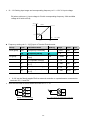
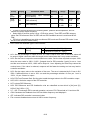
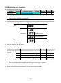
4.6 Monitoring of operation status
Output current display
Monitoring output current in Drive group
Drive group
1
2
3
4
-. In [0.0], continue pressing the Up () or Down () key until [CUr] is
displayed.
-. Monitoring output current is provided in this parameter.
-. Press the Enter () key once to check the current.
-. Present output current is 5 A.
-. Press the Enter () key once to return to the parameter name.
-. Return to the output current monitoring code.
Other parameters in Drive group such as dCL (Inverter DC link voltage) or vOL (Inverter
output voltage) can be monitored via the same method.
4-13
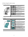
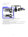
Fault display
How to monitor fault condition in Drive group
During
Accel
Overcurrent
trip
Current
Frequency
STOP
RESET
Drive group
-. This message appears when an Overcurrent fault occurs.
-. Press the Enter () key or UP/Down key once.
-. The run frequency at the time of fault (30.0) is displayed.
-. Press the Up () key once.
-. The output current at the time of fault is displayed.
1
2
3
-. Press the Up () key once.
-. Operating status is displayed. A fault occurred during acceleration.
4
-. Press the STOP/RST key once.
-. A fault condition is cleared and “nOn” is displayed.
5
When more than one fault occurs at the same time
-. Maximum three faults information is
displayed as shown left.
Motor
overheat
Over
voltage
Over
current
Drive group
4-14
Parameter initialize
How to initialize parameters of all four groups in H93
FU group 2
1
-. In H0, press the Enter () key once.
2
-. Code number of H0 is displayed.
-. Increase the value to 3 by pressing the Up () key.
3
-. In 3, press the Left () key once to move the cursor to the left.
4
5
6
7
-. 03 is displayed. 0 in 03 is active.
-. Increase the value to 9 by pressing the Up () key.
-. 93 is set.
-. Press the Enter () key once.
-. The parameter number is displayed.
-. Press the Enter () key once.
-. Present setting is 0.
-. Press the Up () key once to set to 1 to activate parameter initialize.
8
-. Press the Enter () key once.
9
-. Return to the parameter number after blinking. Parameter initialize has
been complete.
-. Press the either Left () or Right () key.
10
-. Return to H0.
4-15
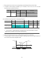
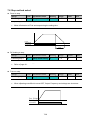
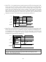
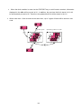
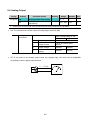
4.7 Frequency Setting and Basic Operation
☞ Caution : The following instructions are given based on the fact that all parameters are set to
factory defaults. Results could be different if parameter values are changed. In this case, initialize
parameter values (see page 10-21) back to factory defaults and follow the instructions below.
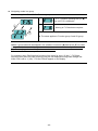
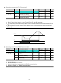
Frequency Setting via keypad & operating via terminals
1
-. Apply AC input power to the inverter.
2
-. When 0.00 appears, press the Ent () key once.
3
-. The second digit in 0.00 is lit as shown right.
-. Press the Left () key three times.
4
-. 00.00 is displayed and the first 0 is lit.
-. Press the Up () key.
5
-. 10.00 is set. Press the Ent () key once.
-. 10.00 is blinking. Press the Ent () key once.
6
-. Run frequency is set to 10.00 Hz when the blinking stops.
-. Turn on the switch between P1 (FX) and CM terminals.
7
-. RUN lamp begins to blink with FWD (Forward Run) lit and accelerating
frequency is displayed on the LED.
-. When target run frequency 10Hz is reached, 10.00 is displayed.
-. Turn off the switch between P1 (FX) and CM terminals.
8
-. RUN lamp begins to blink and decelerating frequency is displayed on the
LED.
-. When run frequency is reached to 0Hz, Run and FWD lamp turn off and 10.00
is displayed.
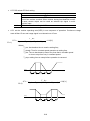
3P
AC
Input
R
S
T
U
V
W
Motor
10 Hz
Freq.
G
P1(FX)
CM
P1(FX)-CM
Wiring
ON
Operating pattern
4-16
OFF
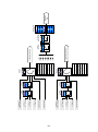
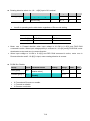
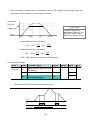
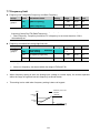
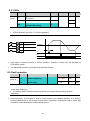
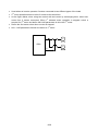
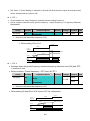
Frequency Setting via potentiometer & operating via terminals
1
-. Apply AC input power to the inverter.
2
-. When 0.00 appears Press the Up () key four times.
3
-. Frq is displayed. Frequency setting mode is selectable.
-. Press the Ent () key once.
4
-. Present setting method is set to 0 (frequency setting via keypad).
-. Press the Up () key three times.
5
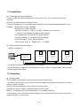
-. After 3 (Frequency setting via potentiometer) is set, press the Ent () key once.
6
-. Frq is redisplayed after 3 stops blinking.
-. Press the Down () key four times.
-. Turn the potentiometer to set to 10.00 Hz in either Max or Min direction.
7
-. Turn on the switch between P1 (FX) and CM (See Wiring below).
-. RUN lamp begins to blink with FWD lamp lit and the accelerating frequency is
displayed on the LED.
-. When run frequency 10Hz is reached, the value is displayed as shown left.
-. Turn off the switch between P1 (FX) and CM terminals.
8
-. RUN lamp begins to blink and decelerating frequency is displayed on the LED.
-. When run frequency is reached to 0Hz, Run and FWD lamp turn off and 10.00
is displayed.
3P AC
input
R
S
T
U
V
W
Motor
10 Hz
Freq.
P1(FX)
G
P1(FX)-CM
CM
ON
VR
V1
CM
Wiring
Operating pattern
4-17
OFF
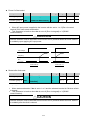
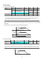
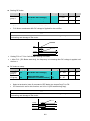
Frequency setting via potentiometer & operating via the Run key
1
-. Apply AC input power to the inverter.
2
-. When 0.00 is displayed, press the Up () key three times.
3
-. “drv” is displayed. Operating method is selectable.
-. Press the Ent () key.
4
-. Check the present operating method (“1”: Run via control terminal).
-. Down () key once.
5
-. After setting “0”, press the Ent () key. When 0 is blinking, press the Ent
again.
6
-. “drv” is displayed after “0” is blinking. Operation method is set via the Run key
on the keypad. -. Press the Up () key once.
7
-. Different frequency setting method is selectable.
-. Press the Ent () key.
8
-. Check the present frequency setting method (“0” is run via keypad).
-. Press the Up () key three times.
9
-. After checking “3” (frequency setting via potentiometer), press the Ent () key.
10
-. “Frq” is displayed after “3” is blinking. Frequency setting is set via the
potentiometer on the keypad.
-. Press the Down () key four times.
-. Turn the potentiometer to set to 10.0 Hz in either Max or Min direction.
11
-. Press the Run key on the keypad.
-. RUN lamp begins to blink with FWD lamp lit and accelerating frequency is
displayed on the LED.
-. When run frequency 10Hz is reached, 10.00 is displayed as shown left.
-. Press the STOP/RST key.
12
-. RUN lamp begins to blink and decelerating frequency is displayed on the
LED.
-. When run frequency is reached to 0Hz, Run and FWD lamp turn off and 10.00
is displayed.
R
S
T
U
V
W
Motor
10 Hz
Freq.
Keypad
Run key
G
VR
STOP/RST key
V1
CM
Wiring
Operating pattern
4-18
Notes:
4-19
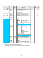
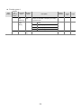
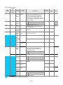
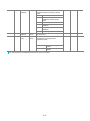
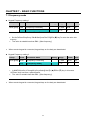
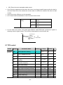
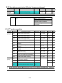
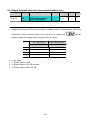
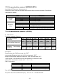
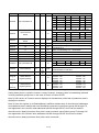
CHAPTER 5 - FUNCTION LIST
Drive Group
LED
display
Address
for
communi
cation
0.00
A100
[Frequency
command]
0~
400
[Hz]
ACC
A101
dEC
A102
0~
6000
[Sec]
drv
A103
[Accel
time]
[Decel
time]
[Drive
mode]
Parameter
name
Min/
Max
range
0~4
Factory
defaults
Description
This parameter sets the frequency that the
inverter is commanded to output.
During Stop: Frequency Command
During Run: Output Frequency
During Multi-step operation:
Multi-step frequency 0.
It cannot be set greater than F21- [Max
frequency].
During Multi-Accel/Decel operation, this
parameter serves as Accel/Decel time 0.
0 Run/Stop via Run/Stop key on the keypad
Adj.
during
run
0.00
O
7-1
5.0
O
7-12
10.0
O
7-12
1
X
7-8
FX: Motor forward run
RX: Motor reverse run
FX: Run/Stop enable
2
RX: Reverse rotation select
3 RS485 communication
1
Page
7-8
Terminal
operation
7-9
4 Set to Field Bus communication 1)
Frq
A104
[Frequency
setting
method]
0~9
0 Digital
1
2
3
4
Analog
5
6
Keypad setting 1
Keypad setting 2
V1 1: -10 ~ +10 [V]
V1 2: 0 ~ +10 [V]
Terminal I: 0 ~ 20 [mA]
Terminal V1 setting 1 +
Terminal I
Terminal V1 setting 2+
Terminal I
0
X
7-6
7-5
7 RS485 communication
8 Digital Volume
9 Set to Field Bus communication
0~
400
[Hz]
7-6
1)
St1
A105
St2
A106
St3
A107
CUr
A108
rPM
A109
dCL
A10A
1)
function can be available with iG5A Communication Option Module.
: This
[Multi-Step
frequency
1]
[Multi-Step
frequency
2]
[Multi-Step
frequency
3]
[Output
current]
[Motor
RPM]
[Inverter
DC link
voltage]
7-1
7-1
7-2
7-3
7-4
7-5
-
Sets Multi-Step frequency 1 during Multi-step
operation.
10.00
O
7-7
Sets Multi-Step frequency 2 during Multi-step
operation.
20.00
O
7-7
Sets Multi-Step frequency 3 during Multi-step
operation.
30.00
O
7-7
Displays the output current to the motor.
-
-
9-1
Displays the number of Motor RPM.
-
-
9-1
Displays DC link voltage inside the inverter.
-
-
9-1
5-1
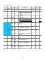
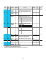
Drive Group
LED
display
Address
for
communi
cation
vOL
A10B
nOn
A10C
drC
A10D
drv2
A10E
Parameter
name
Min/
Max
range
[User
display
select]
This parameter displays the item selected at
H73- [Monitoring item select].
vOL
Output voltage
[Fault
Display]
[Direction
of motor
rotation
select]
POr
Output power
tOr
Torque
Displays the types of faults, frequency and
operating status at the time of the fault
Sets the direction of motor rotation when drv [Drive mode] is set to either 0 or 1.
F
Forward
r
Reverse
Run/Stop
via Run/Stop key on the keypad
0
[Drive
mode 2]
F, r
0~4
Factory
defaults
Description
Adj.
during
run
Page
vOL
-
9-2
-
-
9-4
F
O
7-8
1
X
8-24
0
X
8-24
If H58 is 0, it is expressed as a [Hz] unit.
If H58 is 1, it is expressed as a [%] unit.
In [Hz] unit, you can‟t set Max. frequency
more than (F21).
In [%] unit, 100% means Max. frequency.
0.00
0
8-11
It indicates a feedback amount in PID
control.
If H58 is 0, it is expressed as a [Hz] unit.
If H58 is 1, it is expressed as a [%] unit.
-
-
8-11
FX: Motor forward run
RX: Motor reverse run
FX: Run/Stop enable
2
RX: Reverse rotation select
3 RS-485 communication
1
Terminal
operation
4 Set to Filed Bus Communication 3)
Frq2
1)
A10F
[Frequency
setting
method 2]
0~9
0 Digital
1
2 Analog
3
4
5
6
Keypad setting 1
Keypad setting 2
V1 1: -10 ~ +10 [V]
V1 2: 0 ~ +10 [V]
Terminal I: 0 ~ 20 [mA]
Terminal V1 setting 1 +
Terminal I
Terminal V1 setting 2+
Terminal I
7 RS485 communication
8 Digital Volume
9 Set to Filed Bus Communication 3)
rEF
2)
A110
PID control
standard
value
setting
2)
A111
PID control
feedback
amount
Fbk
0~400
[Hz] or
0~100
[%]
1)
: Only displayed when one of the Multi-function input terminals 1-8 [I17~I24] is set to “22”.
2)
: It is indicated when H49(PID control selection) is 1.
3)
: This function can be available with iG5A Communication Option Module.
5-2
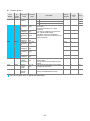
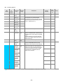
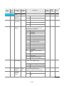
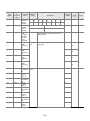
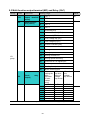
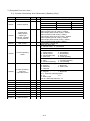
Function group 1
LED
display
F0
Address
for
communi
cation
A200
F1
A201
Paramet
er name
Adj.
during
run
Factory
defaults
Page
0 ~ 71
Sets the parameter code number to jump.
1
O
4-5
[Forwar
d/
Reverse
run
disable]
0~2
0
Fwd and rev run enable
0
X
7-10
1
Forward run disable
2
Reverse run disable
0~1
0
Linear
0
X
7-15
1
S-curve
0
Decelerate to stop
0
X
7-20
1
DC brake to stop
2
Free run to stop
3
Power Braking stop
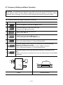
A202
[Accel
pattern]
F3
A203
[Decel
pattern]
F4
A204
[Stop
mode
select]
1)
Description
[Jump
code]
F2
F8
Min/Max
range
0~3
8-26
A208
[DC
Brake
start
frequen
cy]
0.1 ~ 60
[Hz]
This parameter sets DC brake start
frequency.
It cannot be set below F23 - [Start
frequency].
5.00
X
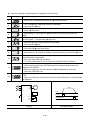
F9
A209
[DC
Brake
wait
time]
0 ~ 60
[sec]
When DC brake frequency is reached,
the inverter holds the output for the
setting time before starting DC brake.
0.1
X
F10
A20A
[DC
Brake
voltage]
0 ~ 200
[%]
This parameter sets the amount of DC
voltage applied to a motor.
It is set in percent of H33 – [Motor rated
current].
50
X
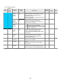
F11
A20B
[DC
Brake
time]
0 ~ 60
[sec]
This parameter sets the time taken to
apply DC current to a motor while motor
is at a stop.
1.0
X
F12
A20C
[DC
Brake
start
voltage]
0 ~ 200
[%]
This parameter sets the amount of DC
voltage before a motor starts to run.
It is set in percent of H33 – [Motor rated
current].
50
X
F13
A20D
[DC
Brake
start
time]
0 ~ 60
[sec]
DC voltage is applied to the motor for DC
Brake start time before motor
accelerates.
0
X
F14
A20E
[Time
for
magneti
zing a
motor]
0 ~ 60
[sec]
This parameter applies the current to a
motor for the set time before motor
accelerates during Sensorless vector
control.
0.1
X
8-15
F20
A214
[Jog
frequen
cy]
0 ~ 400
[Hz]
This parameter sets the frequency for
Jog operation.
It cannot be set above F21 – [Max
frequency].
10.00
O
8-3
1)
: Only displayed when F 4 is set to 1 (DC brake to stop).
5-3
8-1
8-2
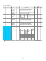
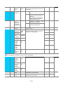
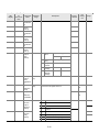
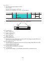
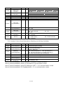
Function group 1
LED
display
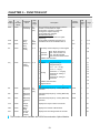
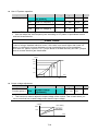
F21
1)
Address
for
communi
cation
A215
Paramete
r name
Min/Max
range
[Max
frequency
]
40 ~ 400
[Hz]
Description
This parameter sets the highest frequency
the inverter can output.
It is frequency reference for Accel/Decel
(See H70)
Factory
defaults
Adj.
during
run
Page
60.00
X
7-21
Caution
Any frequency cannot be set above Max
frequency except Base frequency
F22
A216
[Base
frequency
]
30 ~ 400
[Hz]
The inverter outputs its rated voltage to the
motor at this frequency (see motor
nameplate).
60.00
X
7-17
F23
A217
[Start
frequency
]
0.1 ~ 10
[Hz]
The inverter starts to output its voltage at
this frequency.
It is the frequency low limit.
0.50
X
7-21
F24
A218
[Frequen
cy
high/low
limit
select]
0~1
This parameter sets high and low limit of
run frequency.
0
X
7-21
F25
A219
[Frequen
cy high
limit]
0 ~ 400
[Hz]
This parameter sets high limit of the run
frequency.
It cannot be set above F21 – [Max
frequency].
60.00
X
F26
A21A
[Frequen
cy low
limit]
0 ~ 400
[Hz]
This parameter sets low limit of the run
frequency.
It cannot be set above F25 - [Frequency
high limit] and below F23 – [Start
frequency].
0.50
X
F27
A21B
[Torque
Boost
select]
0~1
0 Manual torque boost
0
X
7-19
0 ~ 15
[%]
This parameter sets the amount of torque
boost applied to a motor during forward
run.
It is set in percent of Max output voltage.
2
X
7-19
This parameter sets the amount of torque
boost applied to a motor during reverse
run.
It is set as a percent of Max output voltage
2
X
7-19
2)
F28
A21C
[Torque
boost in
forward
direction]
F29
A21D
[Torque
boost in
reverse
direction]
1 Auto torque boost
1)
: If H40 is set to 3 (Sensorless vector), Max. frequency is settable up to 300Hz.
2)
: Only displayed when F24 (Frequency high/low limit select) is set to 1.
5-4
Function group 1
LED
display
F30
F31
Address
for
commu
nication
A21E
1)
Parameter
name
[V/F
pattern]
Min/Max
range
0~2
A21F
[User V/F
frequency
1]
0 ~ 400
[Hz]
F32
A220
[User V/F
voltage 1]
0 ~ 100
[%]
F33
A221
[User V/F
frequency
2]
0 ~ 400
[Hz]
F34
A222
[User V/F
voltage 2]
F35
A223
F36
Description
Adj.
during
run
Factory
defaults
0
{Linear}
1
{Square}
7-17
2
{User V/F}
7-18
It is used only when V/F pattern is set to
2(User V/F)
It cannot be set above F21 – [Max
frequency].
The value of voltage is set in percent of
H70 – [Motor rated voltage].
The values of the lower-numbered
parameters cannot be set above those of
higher-numbered.
0
X
Page
7-17
15.00
X
25
X
30.00
X
0 ~ 100
[%]
50
X
[User V/F
frequency
3]
0 ~ 400
[Hz]
45.00
X
A224
[User V/F
voltage 3]
0 ~ 100
[%]
75
X
F37
A225
[User V/F
frequency
4]
0 ~ 400
[Hz]
60.00
X
F38
A226
[User V/F
voltage 4]
0 ~ 100
[%]
100
X
F39
A227
[Output
voltage
adjustment
]
40 ~ 110
[%]
This parameter adjusts the amount of
output voltage.
The set value is the percentage of input
voltage.
100
X
7-18
F40
A228
[Energysaving
level]
0 ~ 30
[%]
This parameter decreases output voltage
according to load status.
0
0
8-17
F50
A232
[Electronic
thermal
select]
0~1
This parameter is activated when the
motor is overheated (time-inverse).
0
0
10-1
1)
: Set F30 to 2(User V/F) to display this parameter.
5-5
7-18
Function group 1
LED
display
Address
for
commu
nication
F51
A233
[Electronic
thermal
level for 1
minute]
50 ~ 200
[%]
This parameter sets max current capable of
flowing to the motor continuously for 1 minute.
The set value is the percentage of H33 –
[Motor rated current].
It cannot be set below F52 –[Electronic thermal
level for continuous].
150
0
F52
A234
[Electronic
thermal
level for
continuous]
50 ~ 150
[%]
This parameter sets the amount of current to
keep the motor running continuously.
It cannot be set higher than F51 – [Electronic
thermal level for 1 minute].
100
0
F53
A235
[Motor
cooling
method]
0~1
0
Standard motor having cooling fan
directly connected to the shaft
0
0
1
A motor using a separate motor to
power a cooling fan.
1)
Parameter
name
Min/Max
range
Description
Adj.
during
run
Factory
defaults
F54
A236
[Overload
warning
level]
30 ~ 150
[%]
This parameter sets the amount of current to
issue an alarm signal at a relay or multifunction output terminal (see I54, I55).
The set value is the percentage of H33- [Motor
rated current].
150
0
F55
A237
[Overload
warning
time]
0 ~ 30 [Sec]
This parameter issues an alarm signal when
the current greater than F54- [Overload
warning level] flows to the motor for F55[Overload warning time].
10
0
F56
A238
[Overload
trip select]
0~1
This parameter turns off the inverter output
when motor is overloaded.
1
0
F57
A239
[Overload
trip level]
30 ~ 200
[%]
This parameter sets the amount of overload
current.
The value is the percentage of H33- [Motor
rated current].
180
0
F58
A23A
[Overload
trip time]
0 ~ 60 [Sec]
This parameter turns off the inverter output
when the F57- [Overload trip level] of current
flows to the motor for F58- [Overload trip time].
60
0
1)
: Set F50 to 1 to display this parameter.
5-6
Page
10-1
10-2
10-2
Function group 1
LED
display
F59
Address
for
commun
ication
A23B
Paramete
r name
Min/Max
range
[Stall
preventio
n select]
0~7
This parameter stops accelerating during
acceleration, decelerating during constant
speed run and stops decelerating during
deceleration.
During
Decel
During
constant
run
During Accel
Bit 2
Bit 1
Bit 0
0
-
-
1
-
2
-
3
4
5
6
7
-
Adj.
during
run
Factory
defaults
Description
Page
0
X
10-3
F60
A23C
[Stall
preventio
n level]
30 ~
200
[%]
This parameter sets the amount of current to
activate stall prevention function during Accel,
Constant or Decel run.
The set value is the percentage of the H33[Motor rated current].
150
X
10-3
F61
A23D
[When
Stall
preventio
n during
decelerati
on,
voltage
limit
select
0~1
In Stall prevention run during deceleration, if
you want to limit output voltage, select 1
0
X
8-26
F63
A23F
[Save
up/down
frequency
select]
0~1
This parameter decides whether to save the
specified frequency during up/down
operation.
When 1 is selected, the up/down frequency is
saved in F64.
0
X
8-4
F64
A240
[Save
up/down
frequency
]
If „Save up/down frequency‟ is selected at
F63, this parameter saves the frequency
before the inverter stops or decelerated.
0.00
X
8-4
F65
A241
[Up-down
mode
select]
We can select up-down mode among three
thing
0
X
8-5
1)
2)
0~2
0
Increases goal frequency as a
standard of Max. frequency/Min.
frequency
1
Increases as many as step
frequency according to edge input
2
Available to combine 1 and 2
1)
: It is indicated when setting bit 2 of F59 as 1
2)
: Set F63 to 1 to display this parameter.
5-7
Function group 1
LED
display
Address
for
commun
ication
Parameter
name
Min/Max
range
Description
Adj.
during
run
Factory
defaults
Page
F66
A242
[Up-down
step
frequency]
0~400
[Hz]
In case of choosing F65 as a 1 or 2, it means
increase or decrease of frequency according
to up-down input
0.00
X
8-5
F70
A246
[Draw run
mode
select]
0~3
0
Inverter doesn‟t run as a draw
mode
0
X
8-28
1
V1(0~10V) input draw run
2
I(0~20mA) input draw run
3
V1(-10~10V) input draw run
0.00
0
8-28
F71
A247
[Draw rate]
0~100
[%]
Sets rate of draw
5-8
Function group 2
LED
display
Address
for
commu
nication
Parameter
name
Min/Max
range
H0
A300
[Jump
code]
0~95
Sets the code number to jump.
1
H1
A301
[Fault
history 1]
-
nOn
H2
A302
[Fault
history 2]
-
H3
A303
[Fault
history 3]
-
Stores information on the types of faults,
the frequency, the current and the
Accel/Decel condition at the time of fault.
The latest fault is automatically stored in
the H 1- [Fault history 1].
H4
A304
[Fault
history 4]
-
nOn
H5
A305
[Fault
history 5]
-
nOn
H6
A306
[Reset
fault
history]
0~1
Clears the fault history saved in H 1-5.
Adj.
during
run
Factory
defaults
Description
nOn
nOn
O
-
-
0
O
[Dwell
frequency]
0.1~400
[Hz]
When run frequency is issued, motor
starts to accelerate after dwell frequency
is applied to the motor during H8- [Dwell
time].
[Dwell frequency] can be set within the
range of F21- [Max frequency] and F23[Start frequency].
5.00
X
H8
A308
[Dwell
time]
0~10
[sec]
Sets the time for dwell operation.
0.0
X
H10
A30A
[Skip
frequency
select]
0~1
Sets the frequency range to skip to
prevent undesirable resonance and
vibration on the structure of the machine.
0
X
A30B
[Skip
frequency
low limit 1]
0.1~400
[Hz]
10.00
X
H12
A30C
[Skip
frequency
high limit
1]
Run frequency cannot be set within the
range of H11 thru H16. The frequency
values of the low numbered parameters
cannot be set above those of the high
numbered ones. Settable within the
range of F21 and F23.
15.00
X
H13
A30D
[Skip
frequency
low limit 2]
20.00
X
H14
A30E
[Skip
frequency
high limit
2]
25.00
X
H15
A30F
[Skip
frequency
low limit 3]
30.00
X
H16
A310
[Skip
frequency
high limit
3]
35.00
X
1)
9-4
-
A307
1)
4-5
-
H7
H11
Page
: only displayed when H10 is set to 1. # H17, H18 are used when F2, F3 are set to 1 (S-curve).
5-9
8-7
7-22
Function group 2
Factory
defaults
Adj.
during
run
Page
Set the speed reference value to form a
curve at the start during accel/decel. If it is
set higher, linear zone gets smaller.
40
X
7-15
1~100
[%]
Set the speed reference value to form a
curve at the end during accel/decel. If it is set
higher, linear zone gets smaller.
40
X
[Input/output
phase loss
protection
select]
0~3
0
Disabled
1
Output phase
protection
0
O
10-4
2
Input
phase
protection
3
Input/output phase
protection
LED
display
Address for
communication
Parameter
name
Min/Max
range
H17
A311
[S-Curve
accel/decel
start side]
1~100
[%]
H18
A312
[S-Curve
accel/decel
end side]
H19
A313
Description
H20
A314
[Power On
Start select]
0~1
This parameter is activated when drv is set to
1 or 2 (Run/Stop via Control terminal).
Motor starts acceleration after AC power is
applied while FX or RX terminal is ON.
0
O
7-11
H21
A315
[Restart
after fault
reset
selection]
0 ~1
This parameter is activated when drv is set to
1 or 2 (Run/Stop via Control terminal).
Motor accelerates after the fault condition is
reset while the FX or RX terminal is ON.
0
O
7-11
H22
A316
[Speed
Search
Select]
0 ~ 15
This parameter is active to prevent any
possible fault when the inverter outputs its
voltage to the running motor.
0
X
8-17
1)
1)
1. H20[Power
On start]
2.
Restar
t after
instant
power
failure
3.
Operatio
n after
fault
4.
Normal
accel
Bit 3
Bit 2
Bit 1
Bit 0
0
-
-
-
-
1
-
-
2
-
-
3
-
4
-
-
-
Normal acceleration has first priority. Even though #4 is selected along with other bits, Inverter performs Speed search
#4.
5-10
Function group 2
LED
display
H22
1)
Address
for
communic
ation
A316
Paramete
r name
Min/Max
range
Description
1. H20[Power
On
start]
5
6
7
H23
A317
H24
A318
H25
A319
H26
A31A
[Current
level
during
Speed
search]
[P gain
during
Speed
search]
[I gain
during
speed
search]
[Number
of Auto
Restart
try]
80~200
[%]
Factor
y
default
s
Bit 3
-
2.
Restart
after
instant
power
failure
Bit 2
3.
Operati
on after
fault
4.
Nor
mal
accel
Bit 1
Bit 0
-
-
Adj.
during
run
O
8-17
100
O
8-17
8
9
10
11
12
13
14
15
This parameter limits the amount of current
during speed search.
The set value is the percentage of the H33[Motor rated current].
0~9999
It is the Proportional gain used for Speed
Search PI controller.
100
O
0~9999
It is the Integral gain used for Speed search
PI controller.
200
O
0 ~10
This parameter sets the number of restart
tries after a fault occurs.
Auto Restart is deactivated if the fault
outnumbers the restart tries.
This function is active when [drv] is set to 1 or
2 {Run/Stop via control terminal}.
Deactivated during active protection function
(OHT, LVT, EXT, HWT etc.).
0
O
5-11
Page
8-20
Function group 2
LED
display
Address
for
communi
cation
Parameter
name
Min/Max
range
Factory
defaults
Description
H27
A31B
[Auto Restart
time]
0~60 [sec]
This parameter sets the time
between restart tries.
1.0
H30
A31E
[Motor type
select]
0.2~ 22.0
0.2
0.2kW
7.5
~
~
22.0
22.0kW
H31
A31F
[Number of
motor poles]
2 ~ 12
H32
A320
[Rated slip
frequency]
0 ~ 10
[Hz]
This setting is displayed via rPM
in drive group.
rpm P
fs fr
120
1)
4
2.33
Adj.
during run
Page
O
8-20
X
8-16
X
2)
X
Where, f s = Rated slip frequency
f r = Rated frequency
rpm = Motor nameplate
RPM
P = Number of Motor
poles
H33
A321
[Motor rated
current]
0.5~150
[A]
Enter motor rated current on the
nameplate.
26.3
X
H34
A322
[No Load
Motor Current]
0.1~ 100 [A]
Enter the current value detected
when the motor is rotating in rated
rpm after the load connected to
the motor shaft is removed.
Enter the 50% of the rated current
value when it is difficult to
measure H34 – [No Load Motor
Current].
11
X
H36
A324
[Motor
efficiency]
50~100
[%]
Enter the motor efficiency (see
motor nameplate).
87
X
H37
A325
[Load inertia
rate]
0~2
Select one of the following
according to motor inertia.
0
X
0
Less than 10 times
1
About 10 times
2
More than 10 times
1)
: H30 is preset based on inverter rating.
2)
: H32 ~ H36 factory default values are set based on OTIS-LG motor.
5-12
8-1
Function group 2
LED
display
Address
for
communi
cation
Paramet
er name
Min/Max
range
Description
Adj.
during
run
Factory
defaults
Page
H39
A327
[Carrier
frequen
cy
select]
1 ~ 15
[kHz]
This parameter affects the audible sound
of the motor, noise emission from the
inverter, inverter temp, and leakage
current. If the set value is higher, the
inverter sound is quieter but the noise
from the inverter and leakage current will
become greater.
3
O
8-21
H40
A328
[Control
mode
select]
0~3
0
{Volts/frequency Control}
0
X
7-17
1
{Slip compensation control}
3
{Sensorless vector control}
8-8
8-15
H41
A329
[Auto
tuning]
0~1
If this parameter is set to 1, it
automatically measures parameters of
the H42 and H44.
0
X
H42
A32A
[Stator
resistan
ce (Rs)]
0 ~ 28
[]
This is the value of the motor stator
resistance.
-
X
H44
A32C
[Leakage
inductanc
e (L)]
0~ 300.0
[mH]
This is leakage inductance of the stator
and rotor of the motor.
-
X
H45
A32D
[Sensorl
ess P
gain]
0~ 32767
P gain for Sensorless control
1000
O
H46
A32E
[Sensorl
ess I
gain]
I gain for Sensorless control
100
O
H47
A32F
[Sensorl
ess
torque
limit]
100~220[
%]
Limits output torque in sensorless mode,.
180.0
X
H48
A330
PWM
mode
select
0~1
If you want to limit a inverter leakage
current, select 2 phase PWM mode.
It has more noise in comparison to
Normal PWM mode.
0
X
8-30
1)
0
Normal PWM mode
1
2 phase PWM mode
8-14
H49
A331
PID
select
0~1
Selects whether using PID control or not
0
X
8-10
H50
A332
[PID F/B
select]
0~2
0
Terminal I input (0 ~ 20 mA)
0
X
8-10
1
Terminal V1 input (0 ~ 10 V)
2
RS-485 communication feedback
300.0
O
2)
H51
A333
[P gain
for PID]
0~ 999.9
[%]
H52
A334
[Integral
time for
PID
0.1~32.0
[sec]
1.0
O
H53
A335
[Differen
tial time
for PID
(Dgain)]
0 ~ 30.0
[sec]
0.0
O
H54
A336
0
X
This parameter sets the gains for the PID
controller.
[PID
0~1
Selects PID control mode
control
0
Normal PID control
mode
1
Process PID control
select]
1)
: Set H40 to 3 (Sensorless vector control) to display this parameter.
2)
: Set H49 to 1 (PID control) to display this parameter.
5-13
8-10
Function group 2
LED
display
Address
for
communication
Parameter
name
Min/Max
range
H55
A337
[PID output
frequency
high limit]
0.1 ~
400
[Hz]
H56
A338
[PID output
frequency
low limit]
0.1 ~
400
[Hz]
H57
A339
[PID
standard
value select]
0~4
H58
A33A
H60
H61
A33C
1)
PID control
unit select
[Selfdiagnostic
select]
0~1
0~3
Description
Factory
defaults
Adj.
during
run
Page
This parameter limits the amount of the
output frequency through the PID control.
The value is settable within the range of
F21 – [Max frequency] and F23 – [Start
frequency].
60.00
O
0.50
O
Selects PID standard value.
Standard value is indicated in “rEF” of
Drive group.
0
X
0
X
0
X
8-22
8-13
0
Loader digital setting 1
1
Loader digital setting 2
2
V1 terminal setting 2: 0~10V
3
I terminal setting: 0~20mA
4
Setting as a RS-485
communication
Selects a unit of the standard value or
feedback amount.
0
Frequency[Hz]
1
Percentage[%]
0
Self-diagnostic disabled
1
IGBT fault/Ground fault
2
Output phase short & open/
Ground fault
3
Ground fault (This setting is
unable when more than 11kW)
A33D
[Sleep delay
time]
0~2000
[s]
Sets a sleep delay time in PID drive.
60.0
X
H62
A33E
[Sleep
frequency]
0~400
[Hz]
Sets a sleep frequency when executing a
sleep function in PID control drive.
You can‟t set more than Max.
frequency(F21)
0.00
O
H63
A33F
[Wake up
level]
0~100
[%]
Sets a wake up level in PID control drive.
35.0
O
H64
A340
[KEB drive
select]
0~1
Sets KEB drive.
0
X
H65
A341
[KEB action
start level]
110~140
[%]
Sets KEB action start level according to
level.
125.0
X
H66
A342
[KEB action
stop level]
110~145
[%]
Sets KEB action stop level according to
level.
130.0
X
1):
Set H49 as a 1
it is indicated when setting H64(KEB drive select) as a 1
(KEB does not operate when cut power after loading ting input (about 10%).
2):
5-14
8-10
8-10
8-28
Function group 2
LED
display
Address
for
communication
Parameter
name
Min/Max
range
Description
Factory
defaults
Adj.
during
run
Page
H67
A343
[KEB action
gain]
1~2000
0
Sets KEB action gain.
1000
X
8-28
H70
A346
[Frequency
Reference
for
Accel/Decel]
0~1
0
Based on Max freq (F21)
0
X
7-12
1
Based on Delta freq.
[Accel/Decel
time scale]
0~2
0
Settable unit: 0.01 second.
1
O
7-13
1
Settable unit: 0.1 second.
2
Settable unit: 1 second.
0
O
9-2
0
O
9-2
H71
H72
H73
A347
A348
A349
[Power on
display]
[Monitoring
item select]
0 ~ 17
0~2
This parameter selects the parameter to
be displayed on the keypad when the
input power is first applied.
0
Frequency command
1
Accel time
2
Decel time
3
Drive mode
4
Frequency mode
5
Multi-Step frequency 1
6
Multi-Step frequency 2
7
Multi-Step frequency 3
8
Output current
9
Motor rpm
10
Inverter DC link voltage
11
User display select (H73)
12
Fault display
13
Direction of motor rotation
select
14
Output current 2
15
Motor rpm 2
16
Inverter DC link voltage 2
17
User display select 2
One of the following can be monitored
via vOL - [User display select].
0
Output voltage [V]
1
Output power [kW]
2
Torque [kgf m]
H74
A34A
[Gain for
Motor rpm
display]
1~
1000
[%]
This parameter is used to change the
motor rotating speed (r/min) to
mechanical speed (m/mi) and display it.
100
O
9-1
H75
A34B
[DB resistor
operating
rate limit
select]
0~1
0
Unlimited
1
O
10-8
1
Use DB resistor for the H76 set
time.
5-15
H76
H77
1)
H78
A34C
[DB resistor
operating
rate]
0~
30[%]
Set the percent of DB resistor operating
rate to be activated during one sequence
of operation.
10
O
A34D
[Cooling fan
control]
0~1
0
Always ON
0
O
8-30
1
Keeps ON when its temp is
higher than inverter protection
limit temp.
Activated only during operation
when its temp is below that of
inverter protection limit.
0
Continuous operation when
cooling fan malfunctions.
0
O
8-31
1
Operation stopped when
cooling fan malfunctions.
A34E
[Operating
method
select when
cooling fan
malfunctions
]
0~1
A34F
[S/W
version]
x.xx
This parameter displays the inverter
software version.
x.xx
X
-
A351
[2 motor
Accel time]
O
8-21
A352
[2 motor
Decel time]
This parameter actives when the
selected terminal is ON after I17-I24 is
nd
set to 12 {2 motor select}.
5.0
H82
0~
6000
[sec]
10.0
O
H83
A353
[2 motor
base
frequency]
H84
A354
[2 motor
V/F pattern]
H85
A355
[2 motor
forward
torque
boost]
H86
A356
[2 motor
reverse
torque
boost]
H87
A357
H88
A358
[2 motor
Electronic
thermal
level for 1
min]
H89
A359
[2 motor
Electronic
thermal
level for
continuous]
H90
A35A
H79
H81
2)
nd
nd
nd
30 ~
400 [Hz]
60.00
X
nd
0~2
0
X
nd
0 ~ 15
[%]
5
X
5
X
nd
nd
[2 motor
30~150
150
stall
[%]
prevention
level]
1)
Exception: Since SV004iG5A-2/SV004iG5A-4 is Natural convection type, this code is hidden.
2)
nd
: It is indicated when choosing I17~I24 as a 12 (2 motor select).
H91
H92
1)
X
nd
50~200
[%]
150
O
nd
50~150
[%]
100
O
[2 motor
rated
current]
nd
0.1~100
[A]
26.3
X
A35B
[Parameter
read]
0~1
Copy the parameters from inverter and
save them into remote loader.
0
X
A35C
[Parameter
write]
0~1
Copy the parameters from remote loader
and save them into inverter.
0
X
5-16
8-21
8-32
H93
A35D
[Parameter
initialize]
0~5
This parameter is used to initialize
parameters back to the factory default
value.
0
-
1
All parameter groups are
initialized to factory default
value.
2
Only Drive group is initialized.
3
Only Function group 1 is
initialized.
4
Only Function group 2 is
initialized.
5
Only I/O group is initialized.
0
X
8-32
H94
A35E
[Password
register]
0~
FFFF
Password for H95-[Parameter lock]. Set
as Hexa value.
0
O
8-33
H95
A35F
[Parameter
lock]
0~
FFFF
This parameter is able to lock or unlock
parameters by typing password
registered in H94.
0
O
8-33
1)
UL (Unlock)
Parameter change
enable
L (Lock)
Parameter change
disable
H91,H92 parameters are displayed when Remote option is installed.
5-17
Input/output group
LED
display
Address
for
communi
cation
Parameter
name
Min/Max
range
Description
Factory
defaults
Adj.
during
run
Page
I0
A400
[Jump code]
0 ~ 87
Sets the code number to jump.
1
O
4-5
I2
A402
[NV input
Min voltage]
0 ~ -10
[V]
Sets the minimum voltage of the NV (10V~0V) input.
0.00
O
7-2
I3
A403
[Frequency
correspondi
ng to I 2]
0 ~ 400
[Hz]
Sets the inverter output minimum
frequency at minimum voltage of the NV
input.
0.00
O
I4
A404
[NV input
Max
voltage]
0 ~ -10
[V]
Sets the maximum voltage of the NV
input.
10.0
O
I5
A405
[Frequency
correspondi
ng to I 4]
0 ~ 400
[Hz]
Sets the inverter output maximum
frequency at maximum voltage of the
NV input.
60.00
O
I6
A406
[Filter time
constant for
V1 input]
0 ~ 9999
Adjusts the responsiveness of V1 input
(0 ~ +10V).
10
O
I7
A407
[V1 input
Min voltage]
0 ~ 10
[V]
Sets the minimum voltage of the V1
input.
0
O
I8
A408
[Frequency
correspondi
ng to I 7]
0 ~ 400
[Hz]
Sets the inverter output minimum
frequency at minimum voltage of the V1
input.
0.00
O
I9
A409
[V1 input
Max
voltage]
0 ~ 10
[V]
Sets the maximum voltage of the V1
input.
10
O
I10
A40A
[Frequency
correspondi
ng to I 9]
0 ~ 400
[Hz]
Sets the inverter output maximum
frequency at maximum voltage of the
V1 input.
60.00
O
I11
A40B
[Filter time
constant for
I input]
0 ~ 9999
Sets the input section‟s internal filter
constant for I input.
10
O
I12
A40C
[I input Min
current]
0 ~ 20
[mA]
Sets the minimum current of I input.
4.00
O
I13
A40D
[Frequency
correspondi
ng to I 12]
0 ~ 400
[Hz]
Sets the inverter output minimum
frequency at minimum current of I input.
0.00
O
I14
A40E
[I input Max
current]
0 ~ 20
[mA]
Sets the Maximum current of I input.
20.00
O
I15
A40F
[Frequency
correspondi
ng to I 14]
0 ~ 400
[Hz]
Sets the inverter output maximum
frequency at maximum current of I
input.
60.00
O
7-4
I16
A410
[Criteria for
Analog Input
Signal loss]
0~2
0: Disabled
1: activated below half of set value.
2: activated below set value.
0
O
10-7
I17
A411
[Multifunction
input
terminal P1
define]
0 ~ 27
0
Forward run command
0
O
7-8
1
Reverse run command
2
Emergency Stop Trip
1
O
-
3
Reset when a fault occurs {RST}
I18
A412
[Multifunction
input
terminal P2
define]
5-18
7-2
7-4
-
Input/output group
LED
display
I19
I20
I21
I22
I23
I24
Address
for
communi
cation
A413
A414
A415
A416
A417
A418
Parameter
name
Min/Max
range
Description
[Multifunction
input
terminal P3
define]
4
Jog operation command
5
Multi-Step freq – Low
[Multifunction
input
terminal P4
define]
6
Multi-Step freq – Mid
7
Multi-Step freq – High
[Multifunction
input
terminal P5
define]
8
Multi Accel/Decel – Low
9
Multi Accel/Decel – Mid
[Multifunction
input
terminal P6
define]
10
Multi Accel/Decel – High
11
DC brake during stop
[Multifunction
input
terminal P7
define]
12
2nd motor select
13
-Reserved-
[Multifunction
input
terminal P8
define]
14
-Reserved-
15
Updown
16
Frequency increase
(UP)
command
Factory
defaults
2
Adj.
during
run
O
Page
8-3
7-7
3
O
4
O
5
O
7-14
8-2
6
O
8-21
-
7
O
8-4
Frequency decrease
command (DOWN)
17
3-wire operation
8-7
18
External trip: A Contact (EtA)
10-5
19
External trip: B Contact (EtB)
20
Self-diagnostic function
8-22
21
Change from PID operation to
V/F operation
8-10
22
2 Source
8-24
23
Analog Hold
7-6
24
Accel/Decel Disable
7-16
25
Up/Down Save Freq. Initialization
8-4
26
JOG-FX
8-3
27
JOG-RX
nd
* See “Chapter 14 Troubleshooting and maintenance” for External trip A/B contact.
* Each multi-function input terminal must be set differently.
5-19
Input/output group
LED
display
I25
I26
Address
for
communic
ation
A419
A41A
Parameter
name
Min/Max
range
[Input
terminal
status
display]
BIT
7
BIT
6
BIT
5
BIT
4
BIT
3
BIT
2
BIT
1
BIT
0
P8
P7
P6
P5
P4
P3
P2
P1
[Output
terminal
status
display]
BIT1
BIT0
3AC
MO
-
-
-
O
A41B
[Filtering
time
constant
for Multifunction
Input
terminal]
1 ~ 15
If the value is set higher, the
responsiveness of the Input terminal is
getting slower.
4
I30
A41E
[MultiStep
frequency
4]
0 ~ 400
[Hz]
It cannot be set greater than F21 – [Max
frequency].
30.00
I32
I33
A41F
A420
A421
-
Page
9-3
9-3
I27
I31
Adj.
during
run
Factory
default
Description
-
7-7
O
[MultiStep
frequency
5]
25.00
[MultiStep
frequency
6]
20.00
[MultiStep
frequency
7]
15.00
O
O
O
I34
A422
[MultiAccel time
1]
0~ 6000
[sec]
3.0
I35
A423
[MultiDecel
time 1]
3.0
I36
A424
[MultiAccel time
2]
4.0
I37
A425
[MultiDecel
time 2]
4.0
I38
A426
[MultiAccel time
3]
5.0
I39
A427
[MultiDecel
time 3]
5.0
I40
A428
[MultiAccel time
4]
6.0
I41
A429
[MultiDecel
time 4]
6.0
5-20
O
7-14
Input/output group
LED
display
Address
for
communic
ation
Parameter
name
Min/Max
range
Factory
default
Description
I42
A42A
[MultiAccel time
5]
7.0
I43
A42B
[MultiDecel
time 5]
7.0
I44
A42C
[MultiAccel time
6]
8.0
I45
A42D
[MultiDecel
time 6]
8.0
I46
A42E
[MultiAccel time
7]
9.0
I47
A42F
[MultiDecel
time 7]
9.0
I50
A432
[Analog
output
item
select]
0~3
Output
item
Output to 10[V]
200V
O
9-6
O
9-6
400V
0
Output
freq.
Max frequency
1
Output
current
150 %
2
Output
voltage
AC 282V
AC 564V
3
Inverter
DC link
voltage
DC 400V
DC 800V
A433
[Analog
output
level
adjustmen
t]
10~200
[%]
Based on 10V.
100
I52
A434
[Frequenc
y
detection
level]
0 ~ 400
[Hz]
Used when I54 or I55 is set to 0-4.
Cannot be set higher than F21.
30.00
I54
I55
A435
A436
A437
[Frequenc
y
detection
bandwidth
]
[Multifunction
output
terminal
select]
[Multifunction
relay
select]
Page
0
I51
I53
Adj.
during
run
9-7
O
10.00
O
0 ~ 19
0
FDT-1
1
FDT-2
2
FDT-3
3
FDT-4
4
FDT-5
9-10
5
Overload (OLt)
9-10
6
Inverter Overload (IOLt)
7
Motor stall (STALL)
5-21
12
O
9-8
9-9
17
Input/output group
LED
display
Address
for
communic
ation
Parameter
name
Min/Max
range
Description
8
Over voltage trip (Ovt)
9
Low voltage trip (Lvt)
10
Inverter Overheat (OHt)
11
Command loss
12
During Run
13
During Stop
14
During constant run
15
During speed searching
16
Wait time for run signal input
17
Multi-function relay select
18
Warning for cooling fan trip
19
Brake signal select
5-22
Factory
default
Adj.
during
run
Page
9-11
Input/Output Group
LED
display
I56
Address
for
commun
ication
A438
Paramet
er name
[Fault
relay
output]
Min/Max
range
0~7
I59
A439
A43B
[Output
terminal
select
when
commun
ication
error
occurs]
0 ~1
When the
trip other
than low
voltage trip
occurs
When the
low voltage
trip occurs
Bit 2
Bit 1
Bit 0
-
-
1
-
2
-
3
4
5
6
0~3
[Commu
nication
protocol
select]
When
setting the
H26–
[Number of
auto
restart try]
0
7
I57
Factory
defaults
Description
Multi-function
output terminal
-
-
1
2
3
0
O
9-12
0
X
11-2
-
Set communication protocol.
LS BUS
9-7
0
1
O
Bit 0
Modbus RTU
2
Bit 1
0
Page
-
Multi-function
relay
Adj.
during
run
I60
A43C
[Inverter
number]
1 ~ 250
Set for RS485 communication
1
O
11-2
I61
A43D
[Baud
rate]
0~4
Select the Baud rate of the RS485.
3
O
11-2
0
O
10-7
1.0
O
10-7
I62
I63
A43E
A43F
[Drive
mode
select
after
loss of
frequenc
y
comman
d]
0~2
[Wait
time
after
loss of
frequenc
y
comman
d]
0.1 ~ 120
[sec]
0
1200 [bps]
1
2400 [bps]
2
4800 [bps]
3
9600 [bps]
4
19200 [bps]
It is used when freq command is given via
V1 /I terminal or RS485.
0
Continuous operation at the frequency
before its command is lost.
1
Free Run stop (Output cut-off)
2
Decel to stop
This is the time inverter determines
whether there is the input frequency
command or not. If there is no frequency
command input during this time, inverter
starts operation via the mode selected at
I62.
5-23
I64
A440
[Commu
nication
time
setting]
I65
A441
[Parity/st
op bit
setting]
2 ~ 100
[ms]
Frame communication time
When
the
protocol
is
set,
communication format can be set.
0~3
0
Parity: None, Stop Bit: 1
1
Parity: None, Stop Bit: 2
2
Parity: Even, Stop Bit: 1
3
Parity: Odd, Stop Bit: 1
the
5
O
-
O
O
-
O
11-11
O
11-11
I66
A442
[Read
address
register
1]
5
I67
A443
[Read
address
register
2]
6
I68
A444
[Read
address
register
3]
7
I69
A445
[Read
address
register
4]
8
0~42239
The user can register up to 8
discontinuous addresses and read them all
with one Read command.
I70
A446
[Read
address
register
5]
I71
A447
[Read
address
register
6]
10
I72
A448
[Read
address
register
7]
11
I73
A449
[Read
address
register
8]
12
I74
A44A
[Write
address
register
1]
5
I75
A44B
[Write
address
register
2]
6
I76
A44C
[Write
address
register
3]
0~42239
The user can register up to 8
discontinuous addresses and write them
all with one Write command
9
7
I77
A44D
[Write
address
register
4]
8
I78
A44E
[Write
address
register
5]
5
5-24
I79
A44F
[Write
address
register
6]
6
I80
A450
[Write
address
register
7]
7
I81
A451
[Write
address
register
8]
8
A452
[Brake
open
current]
0~180
[%]
Sets current level to open the brake.
It is set according to H33‟s (motor rated
current) size
50.0
O
183
A453
[Brake
open
delay
time]
0~10
[s]
Sets Brake open delay time.
1.00
X
184
A454
[Brake
open FX
frequenc
y]
0~400
[Hz]
Sets FX frequency to open the brake
1.00
X
185
A455
[Brake
open RX
frequenc
y]
0~400
[Hz]
Sets RX frequency to open the brake
1.00
X
186
A456
[Brake
close
delay
time]
0~19
[s]
Sets delay time to close the brake
1.00
X
187
A457
[Brake
close
frequenc
y
0~400
[Hz]
Sets frequency to close the brake
2.00
X
182
1):
1)
It is indicated when choosing I54~I55 as a 19 (Brake signal).
5-25
8-26
Drive mode
Frequency
setting
Accel/Decel
V/F
control
PWM
Motor
CHAPTER 6 - CONTROL BLOCK DIAGRAM
6-1
6-2
JOG
Frequency
Mult-step
Frequency
2nd Reference
Frequency
1st Reference
Frequency
I/O Group
I17~I24
I/O Group
I17~I24
2nd Reference
Freq. Select
Mult-step Select
1st Reference
Frequency
Mult-function Input
Mult-function Input
① JOG Select
① JOG_FX Select
① JOG_RX Select
I17~I24
I/O Group
Mult-function Input
Final
Reference
Freq.
6.1 Frequency setting
6-3
Communication
I
0 ~ 20 [mA]
V1_2
0 ~ +10 [V]
V1_1
-10 ~ +10 [V]
Keypad or
Remote Keypad
Communication
Digital Volume
I
0 ~ 20 [mA]
V1_2
0 ~ +10 [V]
V1_1
-10 ~ +10 [V]
Keypad or
Remote Keypad
Analog
Input Scale
I/O Group
I 2 ~ I15
I/O Group
I 1, 6, 11
I 2 ~ I15
I 1, 6, 11
Analog
Input Filter
I/O Group
Analog
Input Scale
I/O Group
Analog
Input Filter
Communication
Up-Down Operation
7
8
V1_1:-10 ~ 10V
V1_2 : 0 ~ 10V
I : 0 ~ 20mA
V1_1 + I
V1_2 + I
Communication
3
4
5
6
7
Keypad Setting 2
2
Keypad Setting 1
1
7
0
0
6
3
2 1
Frq
DRV Group
5
4
V1_2 + I
6
2nd Freq.
Select
V1_1 + I
5
V1_2 : 0 ~ 10V
3
I : 0 ~ 20mA
V1_1:-10 ~ 10V
2
4
Keypad Setting 2
8
Keypad Setting 1
7
0
1
6
2 1
0
5
4
3
Frq
DRV Group
1st Freq.
Select
I 27
I/O Group
2nd Reference Freq.
P8
P7
P6
P5
P4
P3
P2
P1
Digital
Input Filter
1st Reference Freq.
5,6,7
I17 ~ I24
I/O Group
Mult-step
Operation Select
I33
I32
I31
I30
I/O Group
St3
St2
St1
DRV Group
Mult-step Freq.
Select
Mult-step
Freq.
6-4
P8
P7
P6
P5
P4
P3
P2
P1
I/O Group
0,1
I17 ~ I24
I/O Group
Digital Input Filter
I 27
Forward/Reverse
Command Select
17
I17 ~ I24
I/O Group
3-Wire
Operation
0
1,2
3
Communication
Keypad
0
1
2
3
drv
Drive Group
Drive Command
Select
2
1
REV Disable
FWD Disable
0 FWD/REV Run
F1
Func. Group 1
Forward/Reverse
Run Disable
Drive
Command
6.2 Drive command setting
6-5
P8
P7
P6
P5
P4
P3
P2
P1
I/O group
I17 ~ I24
I/O group
I27
5,6,7
Multi-Accel/Decel
time select
Digital input filter
F29
F28
Torque
boost value
Func. group 1
F31~F38
Func. group 1
User V/F
Freq., Voltage
I34 ~ I47
1st-7th Accel/
Decel time
I/O group
0
1~7
Automatic
Manual
User V/F
Square
Linear
P1 ~ P8
Run
command
1
0
F27
Func. group 1
Torque boost
select
2
1
0
F30
Func. group 1
V/F pattern
Frequency
setting
1
0
1
0
0
1
+
Optimal time
Shortest time
S-curve
Linear
Reference freq. for Accel/Decel
Accel/Decel
pattern
Func. group1
Func. group1
H70
F2, F3
F21
DEC
Func. group1
ACC
Max freq.
Accel/Decel
time
Drive group
F39
I/O group
Output voltage
adjustment
F8 ~ F11
Func. group1
DC brake freq.
voltage, time
Stop
2
1
0
F23
F22
I/O group
Base/start freq.
FreeRun Stop
DC brake
F4
Func. group1
Stop method select
PWM
F26
F25
I/O group
H7
H8
Dwell operation
Freq. high/low limit
Func. group1
DC brake start freq.
Operation
F8 ~ F11
DC brake voltage
& time
Func. group1
Dwell freq. & time
6.3 Accel/Decel setting and V/F control
Notes:
6-6
CHAPTER 7 - BASIC FUNCTIONS
7.1 Frequency mode
Keypad Frequency setting 1
Group
Code
Drive group 0.00
Frq
Parameter Name
Setting
Range
Initial
Unit
[Frequency Command]
-
0 ~ 400
0.00
Hz
[Frequency mode]
0
0~9
0
Set Frq – [Frequency mode] to 0 {Frequency setting via Keypad 1}.
Set the desired frequency in 0.00 and press the Prog/Ent () key to enter the value into
memory.
The value is settable less than F21 – [Max frequency].
When remote keypad is connected, keypad keys on the body are deactivated.
Keypad Frequency setting 2
Group
Code
Parameter Name
Setting Range
Initial
Unit
Drive group
0.00
[Frequency Command]
-
0 ~ 400
0.00
Hz
Frq
[Frequency mode]
1
0~9
0
Set Frq – [Frequency mode] to 1{Frequency setting via Keypad 2}.
In 0.00, frequency is changed upon pressing the Up ()/Down () key. In this case,
UP/Down keys serve as a potentiometer.
The value is settable less than F21 – [Max frequency].
When remote keypad is connected, keypad keys on the body are deactivated.
7-1
Frequency setting via –10 ~ +10[V] input
Group
Code
Parameter Name
Setting Range
Initial
Unit
Drive group
0.00
[Frequency Command]
-
0 ~400
0.00
Hz
Frq
[Frequency Mode]
2
0~9
0
I2
[NV input minimum voltage]
-
0 ~ -10
0.0
V
I3
[Frequency corresponding to I2]
-
0 ~ 400
0.00
Hz
I4
[NV input max voltage]
-
0 ~ 10
10.00
V
I5
[Frequency corresponding to I4]
-
0 ~ 400
60.00
Hz
I6 ~ I10
[V1 input]
I/O group
Set Frq – [Frequency Mode] to 2.
The set frequency can be monitored in 0.00 - [Frequency Command].
Apply –10V ~ +10V signal between V1 and CM terminal.
Output frequency corresponding to –10V ~ +10V input voltage to V1 terminal
Output freq
(Positive)
-10 ~ +10 V
V1
CM
-10~0[V]
0~10[V]
Input
voltage
When using -10 ~ 10V from external
circuit
Output freq
(Negative)
I 2 ~ I 5: Setting input range and corresponding frequency to -10V ~ 0V V1 input voltage
Ex) when minimum (-) input voltage is -2V with corresponding frequency 10Hz and Max
voltage is –8V with run freq. 50Hz.
V1 input
I4
I2
-8V
-2V
I3
10Hz
50Hz
I5
Set freq.
7-2
I6 ~ I10: Setting input range and corresponding frequency to 0 ~ +10V V1 input voltage
Ex) when minimum (+) input voltage is 2V with corresponding frequency 10Hz and Max
voltage is 8V with run freq.
Set freq.
50Hz
I 10
I8
10Hz
2V
8V
I7
V1 input
I9
Frequency setting via 0 ~ 10 [V] input or Terminal Potentiometer
Group
Code
Parameter Name
Setting
Range
Initial
Unit
Drive group
0.00
[Frequency Command]
-
0 ~400
0.00
Hz
Frq
[Frequency Mode]
3
0~9
0
10
0 ~ 9999
10
-
0 ~ 10
0
V
-
0 ~ 400
0.00
Hz
-
0 ~ 10
10
V
-
0 ~ 400
60.00
Hz
I/O group
I6
I7
I8
I9
I10
[Filter time constant for V1
input]
[V1 input Min voltage]
[Frequency corresponding
to I 7]
[V1 input max voltage]
[Frequency corresponding
to I 9]
Select 3 in Frq code of Drive group.
0-10V can be directly applied from an external controller or a potentiometer connected on
terminals VR, V1 and CM.
Wire the terminals as shown below and refer to I 6 ~ I 10.
VR
V1
V1
CM
CM
0 ~ 10V input via external controller
Wiring of potentiometer
7-3
Frequency setting via 0 ~ 20 [mA] input
Group
Code
Parameter Name
Setting
Range
Initial
Unit
Drive
group
0.00
[Frequency Command]
-
0 ~400
0.00
Hz
Frq
[Frequency Mode]
4
0~9
0
10
0 ~ 9999
10
I/O
group
[Filter time constant for I input]
I11
I12
[I input minimum current]
-
0 ~ 20
4
mA
I13
[Frequency corresponding to I12]
-
0 ~ 400
0.00
Hz
I14
[I input max current]
-
0 ~ 20
20
mA
I15
[Frequency corresponding to I14]
-
0 ~ 400
60.00
Hz
Select 4 in Frq code of Drive group.
Frequency is set via 0~20mA input between I and CM terminal.
Frequency setting via -10 ~ +10[V] voltage input + 0 ~ 20[mA] input
Group
Drive
group
Code
Parameter Name
Setting
Range
Initial
Unit
0.00
[Frequency Command]
-
0 ~400
0.00
Hz
Frq
[Frequency Mode]
5
0~9
0
Select 5 in Frq code of Drive group.
Override function available using Main/Auxiliary speed adjustment
Related code: I 2 ~ I 5, I 6 ~ I10, I11 ~ I15
Override function is to gain precise control and fast response by combining Main and Auxiliary
speed input. Fast response can be achieved by Main speed and precise control can be
accomplished by Aux. speed if the accuracy of Main/Aux speed is set differently.
Follow the setting below when Main speed is given via 0 ~ 20mA with Aux. speed via V1 terminal
(–10 ~ 10V).
When override function is used, select the Main/Aux. speed according to loads used.
7-4
Group
Code
Parameter Name
Setting
Unit
I/O group
I2
I3
I4
I5
I7
[NV input Min voltage]
[Frequency corresponding to I 2]
[NV input Max voltage]
[Frequency corresponding to I 4]
[V1 input Min voltage]
I8
I9
I10
I12
I13
I14
I15
[Frequency corresponding to I 7]
[V1 input max voltage]
[Frequency corresponding to I 9]
[I input minimum current]
[Frequency corresponding to I 12]
[I input max current]
[Frequency corresponding to I 14]
0
0.00
10.00
5.00
0.00
0.00
10.00
5.00
4.00
0.00
20.00
60.00
V
Hz
V
Hz
V
Hz
V
Hz
mA
Hz
mA
Hz
After the above setting is made, if 5V is applied to V1 with 12mA given to terminal I, output
frequency would be 32.5Hz. If –5V is applied to V1 terminal with 12mA given to terminal I, output
frequency would be 27.5Hz.
Frequency setting via 0 ~ 10[V] + 0 ~ 20[mA] input
Group
Drive
group
Code
Parameter Name
Setting
Range
Initial
Unit
0.00
[Frequency Command]
-
0 ~400
0.00
Hz
Frq
[Frequency Mode]
6
0~9
0
Select 6 in Frq code of Drive group.
Related code: I 6 ~ I 10, I 11 ~ I 15
Refer to Frequency setting via -10 ~ +10V voltage input + 0 ~ 20mA input.
Frequency setting via RS 485 communication
Group
Drive
group
Code
Parameter Name
Setting
Range
Initial
Unit
0.0
[Frequency Command]
-
0 ~400
0.00
Hz
Frq
[Frequency Mode]
7
0~9
0
Select 7 in Frq code of Drive group.
Related code: I 59, I 60, I 61
Refer to Chapter 13. RS485 communication.
7-5
Frequency setting via Digital Volume (up-down)
Group
Drive
group
Code
Parameter Name
Setting
Range
Initial
Unit
0.0
[Frequency Command]
-
0 ~400
0.00
Hz
Frq
[Frequency Mode]
8
0~9
0
Select 7 in Frq code of Drive group.
Related code: I 59, I 60, I 61
Refer to Chapter 13. RS485 communication.
Analog Hold
Group
Drive
group
Code
Parameter Name
Setting
Range
Initial
Frq
[Frequency Mode]
2~7
0~9
0
I/O group
I17
~
I24
[Multi-function input terminal
P1 define]
~
[Multi-function input
terminal P8 define]
-
Unit
0
0 ~25
23
7
It is available when Frq code setting is 2 ~ 7.
Select one terminal to use for Analog Hold command among Multi-function input terminal
(P1 ~ P8).
When P8 terminal is selected,
Set freq.
Frequency
P8
Operation
command
7-6
7.2 Multi-Step Frequency setting
Group
Code
Parameter Name
Setting
Range
Initial
Unit
Drive group
0.0
[Frequency Command]
5.0
0 ~ 400
0.00
Hz
Frq
[Frequency Mode]
0
0~9
0
-
St1
[Multi-Step frequency 1]
-
0 ~ 400
10.00
Hz
St2
[Multi-Step frequency 2]
-
20.00
St3
[Multi-Step frequency 3]
-
30.00
I30
[Multi-function input
terminal P6 define]
[Multi-function input
terminal P7 define]
[Multi-function input
terminal P8 define]
[Multi-Step frequency 4]
I31
[Multi-Step frequency 5]
-
25.00
I32
[Multi-Step frequency 6]
-
20.00
I33
[Multi-Step frequency 7]
-
15.00
I22
I/O group
I23
I24
0 ~ 24
5
5
-
6
6
-
7
7
-
30.00
Hz
0 ~ 400
-
Select a terminal to give Multi-step frequency command among P1-P8 terminals.
If terminals P6-P8 are selected, set I22-I24 to 5-7 to give Multi-step frequency command.
Multi-step frequency 0 is settable in Frq – [Frequency mode] and 0.00 – [Frequency
command].
Multi-step frequency 1-3 are set at St1-St3 in Drive group, while Step frequency 4-7 are
set at I30-I33 in I/O group.
Step
2
Step
1
Step
0
Step
3
Freq.
Step
4
Step
7
Step
5
Step
6
P6
P7
P8
FX
RX
7-7
Step
0
Step
freq.
0
1
2
3
4
5
6
7
FX or RX
P8
P7
P6
-
-
7.3 Operating command setting method
Operation via keypad RUN key and STOP/RST key
Group
Code
Parameter Name
Drive group
drv
[Drive mode]
0
[Direction of motor rotation
select]
drC
Setting
Range
Initial
0~4
1
F, r
F
Unit
Set drv – [Drive mode] to 0.
Acceleration is started upon pressing the Run key while operating frequency is set. Motor
decelerates to stop by pressing the STOP/RST key.
Selecting rotation direction is available at drC - [Direction of motor rotation select] when
operating command is issued via keypad.
drC
[Direction of
motor rotation
select]
F
r
Forward
Reverse
When remote keypad is connected, body-embedded keypad
is deactivated.
Forward :
Counter-clockwise
Operating command via FX, RX terminal 1
Group
Code
Parameter Name
Setting
Range
Initial
Drive group
drv
[Drive mode]
1
0~4
1
I/O group
I17
0
0 ~ 27
0
1
0 ~ 27
1
I18
[Multi-function input
terminal P1 define]
[Multi-function input
terminal P2 define]
Set drv – [Drive mode] to 1.
Set I17 and I18 to 0 and 1 to use P1 and P2 as FX and RX terminals.
“FX” is Forward run command and “RX” Reverse run.
Motor is stopped when FX/RX terminal is
ON/OFF at the same time.
Freq.
FX
RX
7-8
Unit
Operating command via FX, RX terminal 2
Group
Code
Parameter Name
Setting
Range
Initial
Drive group
drv
[Drive mode]
2
0~4
1
I/O group
I17
0
0 ~ 27
0
1
0 ~ 27
1
I18
[Multi-function input
terminal P1 define]
[Multi-function input
terminal P2 define]
Unit
Set the drv to 2.
Set I17 and I18 to 0 and 1 to use P1 and P2 as FX and RX terminals.
FX: Operating command setting. Motor runs in forward direction when RX terminal (P2) is
OFF.
RX: Direction of motor rotation select. Motor runs in reverse direction when RX terminal
(P2) is ON.
Freq.
FX
RX
Operating command via RS485 communication
Group
Code
Parameter Name
Setting
Range
Initial
Drive group
drv
[Drive mode]
3
0~4
1
I/O group
I59
[Communication protocol
select]
-
0~1
0
I60
[Inverter number]
-
1 ~ 250
1
I61
[Baud rate]
-
0~4
3
Set the drv to 3.
Set I59, I60 and I61correctly.
Inverter operation is performed via RS485 communication.
Refer to Chapter. 13, RS485 communication.
7-9
Unit
Rotating direction select via –10 ~ +10[V] input of V1 terminal
Group
Code
Parameter Name
Setting
Range
Initial
Drive group
frq
[Frequency setting]
2
0~8
0
drv
[Drive mode]
-
0~4
1
Unit
Set frq to 2.
Inverter is operating as the table below regardless of Drive mode setting.
FWD RUN Command
REV RUN Command
0 ~ +10 [V]
FWD RUN
REV RUN
-10 ~ 0 [V]
REV RUN
FWD RUN
Motor runs in Forward direction when input voltage to V1-CM is 0~10[V] and FWD RUN
command is active. When input voltage polarity is reversed to –10~0[V] during FWD RUN, motor
decelerates to stop and runs in reverse direction.
When input voltage to V1-CM is 0~10[V] and REV RUN command is active, motor runs in
Reverse direction and if -10~0[V] is input, motor rotating direction is reverse.
FX/RX Run Disable
Group
Code
Drive group
drC
Function group 1
F1
Parameter Name
[Direction of motor
rotation select]
[Forward/Reverse run
disable]
Select the direction of motor rotation.
0: Forward and Reverse run enable
1: Forward run disable
2: Reverse run disable
7-10
Setting
Range
Initial
-
F, r
F
-
0~2
0
Unit
Power On Start select
Group
Code
Parameter Name
Setting
Range
Initial
Drive group
drv
[Drive mode]
1, 2
0~4
1
Function group 2
H20
[Power On Start select]
1
0~1
0
Unit
Set H20 to 1.
When AC input power is applied to the inverter with drv set to 1 or 2 {Run via control
terminal} ON, motor starts acceleration.
This parameter is inactive when drv is set to 0 {Run via keypad} or 3 {RS485
communication}.
CAUTION
Particular attention must be directed to this function due to potential hazard as motor starts to
run suddenly upon applying AC input power.
Input voltage
Frequency
Run
command
When H20 is 0
When H20 is 1
Restart after fault reset
Group
Code Parameter Name
Setting
Range
Initial
Drive group
drv
[Drive mode]
1, 2
0~4
1
Function group 2
H21
[Restart after fault reset
selection]
1
0~1
0
Unit
Set H21 to 1.
Motor starts acceleration if drv is set to 1 or 2 and the selected terminal is ON when a fault
is cleared.
This parameter is inactive when drv is set to 0 {Run via keypad} or 3 {RS485
communication}.
CAUTION
Particular attention must be directed to this function due to potential hazard as motor starts to
run suddenly after the fault is cleared.
7-11
Frequency
Reset
Run
command
When H21 is 0
When H21 is 1
7.4 Accel/Decel time and pattern setting
Accel/Decel time setting based on Max frequency
Group
Code
Parameter Name
Setting
Range
Initial
Unit
Drive group
ACC
[Accel time]
-
0 ~ 6000
5.0
Sec
dEC
[Decel time]
-
0 ~ 6000
10.0
Sec
Function group1
F21
[Max Frequency]
-
40 ~ 400
60.00
Hz
Function group2
H70
0
0~1
0
-
0~2
1
H71
[Frequency
Reference for
Accel/Decel]
[Accel/Decel time
scale]
Set the desired Accel/Decel time at ACC/dEC in Drive group.
If H70 is set to 0 {Max frequency}, Accel/Decel time is the time that takes to reach the max
freq from 0 Hz.
Desired Accel/Decel time unit is settable at the H71.
Accel/Decel time is set based on F21 – [Max frequency]. For instance, if F21 is set to 60Hz,
Accel/Decel time 5 sec, and run frequency 30Hz, time to reach 30Hz would be 2.5 sec.
Max. freq.
60Hz
Run Freq.
30Hz
Run
command
Accel time
Decel time
7-12
More precise time unit can be set corresponding to load characteristics as shown below.
In SV-iG5A, number display is available up to 5. Therefore, if time unit is set to 0.01 sec, Max
Accel/Decel time would be 600.00 sec.
Code
H71
Set
value
Name
[Accel/Decel 0
time scale]
1
2
Setting range
Description
0.01~600.00
Setting Unit: 0.01 sec
0.1~6000.0
Setting Unit: 0.1 sec
1~60000
Setting Unit: 1 sec
Accel/Decel time setting based on Operating Frequency
Group
Code
Parameter Name
Setting
Range
Initial
Unit
Drive group
ACC
[Accel time]
-
0 ~ 6000
5.0
Sec
dEC
[Decel time]
-
0 ~ 6000
10.0
Sec
H70
[Frequency
Reference for
Accel/Decel]
1
0~1
0
Function group 2
Accel/Decel time is set at the ACC/dEC.
If you set H70 to 1 {Delta frequency}, Accel/Decel time is the time that takes to reach a
target freq from constant run freq (Current operating freq.).
When H70 and Accel time are set to 1 {Delta frequency} and 5 sec, respectively,
The below graph in Section A shows the change in operating frequency when target frequency is
set to 10Hz at first and then changed to 30Hz.
Operating
freq.
30Hz
Section A
10Hz
Time
5
7
12
Operating
command
5 sec
5 sec
7-13
[Sec]
Multi-Accel/Decel time setting via Multi-function terminals
Group
Code
Drive
group
ACC
dEC
I/O
group
Set
[Accel time]
-
[Decel time]
-
Range
0~
6000
0~
6000
0 ~ 27
Initial
Unit
5.0
Sec
10.0
Sec
I17
[Multi-function input terminal P1 define]
0
I18
[Multi-function input terminal P12 define]
1
1
8
2
9
3
10
4
[Multi-function input terminal P3
define]
[Multi-function input terminal P4
define]
[Multi-function input terminal P5
define]
I19
I20
I21
Parameter Name
I34
[Multi-Accel time 1]
~
~
I47
[Multi-Decel time 7]
-
0~
6000
-
0
Sec
3.0
9.0
Set I19, I20, I21 to 8, 9, 10 if you want to set Multi - Accel/Decel time via P3-P5 terminals.
Multi-Accel/Decel time 0 is settable at ACC and dEC.
Multi-Accel/Decel time 1-7 is settable at I34-I47.
Accel
time 2
Accel
time 1
Accel
Time 0
Frequency
Accel
time 3
Decel
time 4
Decel
time 5
Decel
time 6
Decel
time 7
Accel/Decel
time
0
1
2
3
4
5
6
7
P3
P4
P5
FX
7-14
P5
P4
P3
-
-
Accel/Decel pattern setting
Group
Code
Parameter Name
Setting range
Function
group 1
F2
[Accel pattern]
0
Linear
F3
[Decel pattern]
1
S-curve
[S-Curve Accel/Decel start
side]
[S-Curve Accel/Decel end
side]
0~
100
Function
group 2
H17
H18
Initial
Unit
0
40
%
40
%
Accel/Decel pattern is settable at F2 and F3.
Linear: This is a general pattern for constant torque applications.
S-curve: This curve allows the motor to accelerate and decelerate smoothly.
CAUTION
For S-curve, the actual Accel/Decel time takes longer than the time set by user.
Freq.
Operating
command
Accel
time
Decel
time
H17 sets the starting ratio between S-curve and Linear in 1/2 of Accel/Decel Ref. Frequency. For
smooth Accel/Decel starting, increase H17 to extend S-curve ratio.
H18 sets the ending ratio between S-curve and Linear in 1/2 of Accel/Decel Ref. Frequency. For
smooth and accurate speed arrival and stopping, increase H18 to extend S-curve ratio.
Accel/Decel
1/2 of
Ref. Freq.
Accel/Decel
Ref. Freq
Freq
H17
Accel
Start
H18
Accel
End
H17
Decel
Start
7-15
H18
Decel
End
Note that setting Frequency Ref. for Accel/decel (H70) is set to Max Freq and target freq is set
below Max freq. the shape of S-curve may be distorted.
Accel/decel
Ref Freq
(H70)
Target Freq
CAUTION
If Target Frequency is
below Max Frequency, the
waveform will be shown
with the top portion cut out.
Freq
H17
H18
H17
H18
Accel time for S-curve setting
ACC ACC
H 17
H 18
ACC
2
2
Decel time for S-curve setting
dEC dEC
H 17
H 18
dEC
2
2
ACC, dEC indicate the set time in Drive group.
Accel/Decel Disable
Group
Code
Parameter Name
I/O group
I17
[Multi-function input terminal
P1 define]
~
~
I24
[Multi-function input
terminal P8 define]
Setting
24
Range
0 ~27
Initial
Unit
0
7
Select one terminal among Multi-function input terminals 1-8 to define Accel/Decel disable.
If P8 is selected, set I24 to 24 to activate this function.
Freq.
P8
Operating
command
7-16
7.5 V/F control
Linear V/F pattern operation
Group
Code
Parameter Name
Setting
Range
Initial
Unit
Function group 1
F22
[Base frequency]
-
30 ~ 400
60.00
Hz
F23
[Start frequency]
-
0.1 ~ 10.0
0.50
Hz
F30
[V/F pattern]
0
0~2
0
H40
[Control mode select]
-
0~3
0
Function group 2
Set F30 to 0 {Linear}.
This pattern maintains a linear Volts/frequency ratio from F23 - [Start frequency] to F22[Base frequency]. This is appropriate for constant torque applications.
Base Frequency: Inverter outputs its rated voltage at this level. Enter the motor nameplate
frequency.
Start Frequency: Inverter starts to output its voltage at this level.
Base freq.
Start freq.
Freq.
Inverter rated
voltage
Voltage
Run
command
Square V/F pattern
Group
Code
Parameter Name
Setting
Range
Initial
Function
group 1
F30
[V/F pattern]
1
0~2
0
Unit
Set F30 to 1{Square}.
This pattern maintains squared volts/hertz ratio. Appropriate applications are fans, pumps,
etc.
Voltage
100%
Freq.
Base freq.
7-17
User V/F pattern operation
Group
Code
Parameter Name
Setting
Range
Initial
Function group 1
F30
[V/F pattern]
2
0~2
0
F31
[User V/F frequency 1]
-
0 ~ 400
15.00
Hz
~
~
F38
[User V/F voltage 4]
-
0 ~ 100
100
%
Unit
Select F30 to 2 {User V/F}.
User can adjust the Volt/Frequency ratio according to V/F pattern of specialized motors
and load characteristics.
CAUTION
In case of using a standard induction motor, if this value is set much higher than linear V/F
pattern, it could result in torque shortage or motor overheating due to over-energizing.
When User V/F pattern is active, F28 - [Torque Boost in forward direction] and F29 - [Torque
Boost in reverse direction] are deactivated.
Voltage
100%
F38
F36
Linear
V/F
F34
F32
Freq.
Start
freq.
F31
F33
F35
F37 Base
freq.
Output voltage adjustment
Group
Code
Parameter Name
Setting
Range
Initial
Unit
Function group 1
F39
[Output voltage
adjustment]
-
40 ~ 110
100
%
This function is used to adjust the output voltage of the inverter. This is useful when you
use a motor that has a rated voltage lower than the input voltage.
Voltage
100% setting
100%
70% setting
70%
Freq.
Base freq.
7-18
Manual torque boost
Group
Code
Function
F27
group 1
F28
F29
Parameter Name
Setting
Range
Initial
[Torque Boost select]
0
0~1
0
[Torque boost in forward direction]
-
0 ~ 15
2
Unit
%
[Torque boost in reverse direction]
Set F27 to 0 {Manual torque boost}.
The values of [Torque boost in forward/reverse direction] are set separately in F28 and
F29.
CAUTION
If the boost value is set much higher than required, it may cause motor overheating due to
over-energizing.
Voltage
100%
No torque boost
FX torque
boost
Time
RX torque
boost
FX
RX
Auto torque boost
Group
Code
Parameter Name
Function group 1
F27
Function group 2
H34
Range
Initial
0~1
0
0.1 ~ 100
-
H41
[Torque Boost select] 1
[No
load
motor
Current]
[Auto tuning]
0
0~1
0
H42
[Stator resistance (Rs)]
0 ~ 28
-
Setting
-
Unit
A
Before Auto Torque Boost setting, H34 and H42 should be set correctly (See page 10-6,
10-10).
Select 1{Auto torque boost} in F27.
Inverter automatically calculates torque boost value using motor parameters and outputs
the corresponding voltage.
7-19
7.6 Stop method select
Decel to stop
Group
Code
Parameter Name
Setting
Range
Initial
Function group 1
F4
[Stop mode select]
0
0~3
0
Unit
Select 0 {decel to stop} in F4 code.
Motor decelerates to 0 Hz and stops during the setting time.
Freq.
Operating
command
Decel
time
DC braking to stop
Group
Code
Parameter Name
Setting
Range
Initial
Function group 1
F4
[Stop mode select]
1
0~3
0
Unit
Select 1 {DC brake to stop} in F4 code.
Refer to page 8-1.
Free run stop
Group
Code
Parameter Name
Setting
Range
Initial
Function group 1
F4
[Stop mode select]
2
0~3
0
Unit
Select 2 {Free run stop} in F4 code.
When operating command is turned OFF, Output Frequency and voltage are shut down.
Freq, Voltage
Operating
command
7-20
7.7 Frequency limit
Frequency limit using Max Frequency and Start Frequency
Group
Code
Parameter Name
Setting
Range
Initial
Unit
Function
group 1
F21
[Max frequency]
-
0 ~ 400
60.00
Hz
F23
[Start frequency]
-
0.1 ~ 10
0.50
Hz
Max Frequency: Frequency highest limit. Any frequency cannot be set above [Max
frequency] except for F22 [Base frequency].
Start Frequency: Frequency lowest limit. If a frequency is set lower than this, 0.00 is
automatically set.
Frequency command limit using High/Low limit
Group
Code
Parameter Name
Setting
Range
Initial
Function
group 1
F24
[Frequency
limit select]
1
0~1
0
F25
[Frequency high limit]
-
0 ~ 400
60.00
Hz
F26
[Frequency low limit]
-
0 ~ 400
0.50
Hz
high/low
Unit
Set F24 to 1.
Active run frequency can be set within the range of F25 and F26.
When frequency setting is done via Analog input (voltage or current input), the inverter operates
within the range of high and low limit frequency as shown below.
This setting is also valid when frequency setting is done via keypad.
When freq. limit is not
selected
Freq.
Max freq.
High limit
freq.
Low limit
freq.
10V
0
20mA
7-21
V1(Voltage input)
I (Current input)
Skip frequency
Group
Function
group 2
Code
Parameter Name
Setting
Range
Initial
Unit
H10
[Skip frequency select]
1
0~1
0
H11
[Skip frequency low limit 1] -
0.1 ~ 400
10.00
Hz
~
~
H16
[Skip frequency low limit 3] -
0.1 ~ 400
35.00
Hz
Set H10 to 1.
Run frequency setting is not available within the skip frequency range of H11-H16.
Skip frequency is settable within the range of F21 – [Max frequency] and F23 – [Start
frequency].
Freq.
H16
H15
H14
H13
H12
H11
10V
0
V1(Voltage input)
20mA I (Current input)
Run
command
Freq. Up setting
Freq. Down
setting
When it is desired to avoid resonance attributable to the natural frequency of a mechanical
system, these parameters allow resonant frequencies to be skipped. Three different areas of
[Skip frequency High/Low limit] can be set with the skip frequencies set to either the top or bottom
point of each area. However, during acceleration or deceleration, the run frequency within the set
area is valid.
In the case of increasing frequency setting as shown above, if frequency set value (Analog
setting via voltage, current, or digital setting via keypad) is within the range of Skip frequency, it
maintains Skip freq RS485 communication, frequency low limit value. If the set value is outside
the range, it increases the frequency.
In the case of decreasing frequency setting, if frequency set value (Analog setting via voltage,
current, RS485 communication, or Digital setting via keypad) is within the range of Skip frequency,
it maintains Skip frequency high limit value. If the set value is outside the range, it decreases the
frequency.
7-22
CHAPTER 8 - ADVANCED FUNCTIONS
8.1 DC brake
Stopping motor by DC brake
Group
Function
group 1
Display
Parameter Name
Setting
Range
Default
Unit
F4
[Stop mode select]
1
0~3
0
F8
[DC Brake start frequency]
-
0.1 ~ 60
5.00
Hz
F9
[DC Brake wait time]
-
0 ~ 60
0.1
sec
F10
[DC Brake voltage]
-
0 ~ 200
50
%
F11
[DC Brake time]
-
0 ~ 60
1.0
sec
Set F4 - [Stop mode select] to 1.
F 8: The frequency at which the DC brake will become active.
F 9: Inverter output will hold for this time after F8 - [DC Brake start frequency] before
applying F10 - [DC Brake voltage].
F10: Set this value as a percent of H33 – [Motor rated current].
F11: It sets the time for F10 - [DC Brake voltage] to be applied to the motor after F 9 - [DC
Brake wait time].
CAUTION
If excessive DC Brake voltage is set or DC Brake time is set too long, it may cause motor
overheating and damage to the motor.
Setting F10 or F11 to 0 will disable DC brake.
F 9 – [DC Brake Wait time]: When load inertia is large
F9
Freq.
F11
F8
or F 8 – [DC Brake Start Frequency] is high, over
current trip may occur. It can be prevented using F9.
Voltage
Current
F10
Run
command
In case of DC brake at high load inertia and frequency, change the DC brake controller gain
according to H37 set value.
H37
Load inertia
ratio
0
1
2
8-1
Less than 10 times motor
inertia
10 times motor inertia
Greater than 10 times motor
inertia
Starting DC brake
Group
Function
group 1
Display
Parameter Name
Setting
Range
Default
Unit
F12
[DC Brake start voltage]
-
0 ~ 200
50
%
F13
[DC Brake start time]
-
0 ~ 60
0
sec
F12: It sets the level as a percent of H33 – [Motor rated current].
F13: Motor accelerates after DC voltage is applied for the set time.
CAUTION
If excessive DC Brake voltage is set or DC Brake time is set too long, it may cause motor
overheating and damage to the motor.
Freq.
F13
t
Voltage
Run
command
F12
Setting F12 or F13 to 0 will disable Starting DC brake.
t: After F13 - [DC Brake start time], the frequency is increasing after DC voltage is applied until
the time t.
DC brake at a stop
Group
Display
Parameter Name
Setting
Range
Default
Unit
%
Function
group 1
F12
[DC Brake start voltage]
-
0 ~ 200
50
I/O group
I19
[Multi-function Input
terminal P3 Function select]
11
0 ~ 25
2
F12: It sets the level as a percent of H33 – [Motor rated current].
Select a terminal to issue a command of DC brake at a stop among P1 to P8.
If P3 terminal is set for this function, set I19 to 11 {DC brake during stop}.
CAUTION
If excessive DC Brake voltage is set or DC Brake time is set too long, it may cause motor
overheating and damage to the motor.
Voltage
F12
P3
Run
command
8-2
8.2 Jog operation
Terminal jog operation
Group
Function
group 1
I/O
group
Display
Parameter Name
Setting
Range
Default
Unit
Hz
F20
[Jog frequency]
-
0 ~ 400
10.00
I21
[Multi-function input
terminal P5 define]
4
0 ~ 25
4
Set the desired jog frequency in F20.
Select a terminal from P1 - P8 to use for this setting.
If P5 is set for Jog operation, set I21 to 4 {Jog}.
Jog frequency can be set within the range of F21 - [Max frequency] and F23 – [Start
frequency].
P1
FX : I17 = 0
P5
JOG : I21=4
F20
Frequency
CM
P5 (JOG)
Run
command(FX)
Jog operation overrides all other operations except Dwell operation. Therefore, if Jog frequency
command is entered in the middle of Multi-Step, Up-Down or 3-wire operation, operation is
executed at Jog frequency.
The above diagram is an example when Multi-function input is set to NPN mode.
Terminal jog operation
Terminal JOG FX/RX operation
Group
Function
group 1
I/O
group
Display
F20
I23
I24
Parameter Name
[Jog frequency]
[Multi-function input
terminal P7 define]
[Multi-function input
terminal P8 define]
Setting
Range
Default
Unit
Hz
-
0 ~ 400
10.00
26
0 ~ 27
6
27
0 ~ 27
7
Set the desired jog frequency in F20.
Select a terminal from P1 - P8 to use for this setting.
If P7 is set for Jog operation, set I23 to 26 {Jog}.
Jog frequency„s setting range can be set between Max. frequency (F21) and start frequency
(F23).
The following diagram is an example when reference frequency is 30Hz and Jog frequency is
10 Hz.
8-3
P1
FX : I 17 = 0
P7
JOG : I23=26
CM
30Hz
F20
Frequency
P 7 ( JOG-FX )
Drive
commend(FX)
8.3 UP-DOWN Drive
Up-down storage function
Group
Drive
group
Display
Frq
I17
I22
I/O
group
I23
I24
Function
group 1
F63
F64
Parameter Name
Setting
[Frequency setting method]
[Multi-function input
terminal P1 define]
[Multi-function input
terminal P6 define]
[Multi-function input
terminal P7define]
[Multi-function input
terminal P8define]
[Up-down frequency Save
select]
[Up-down frequency
storage]
8
Range
0~8
0
25
Default
0
0
0 ~ 27
5
15
6
16
7
-
Unit
0~1
-
0
0.00
Select 8 in Frq code of drive group
Select the terminal which uses as a up-down drive among multi-function input (P1~P8)
If you select P7 and P8 as an up-down drive terminal, select each 15 (frequency increase
command) and 16 (frequency decrease command) in the I23 and I24 of I/O group.
If you select P6 terminal as an up-own save initial terminal, select 25 (up-down save
initialization) as above.
Up/down Save function: If F63, „Save up/down frequency‟, is set to 1, the frequency before
the inverter was stopped or decelerated is saved in F64.
While up-down save operates, the user can initialize the saved up-down frequency by setting
multi-function input terminal as a up-down frequency save initialization.
F63
F64
Save up/down frequency select
0
Remove „save up/down frequency‟
1
Set „save up/down frequency‟
Up/down frequency saved
Save up/down frequency
If „Up/Down Save Frequency Initialization‟ signal is input while the multi-function input „Up‟ or
„Down‟ function is applied, this signal is ignored.
8-4
Up-down mode select
Group
Display
Drive
group
Frq
I17
I/O
group
I23
I24
Function
group 1
F65
F66
Parameter Name
[Frequency setting method]
[Multi-function input
terminal P1 define]
[Multi-function input
terminal P7define]
[Multi-function input
terminal P8define]
[Up-down mode select]
[Up-down step frequency]
Setting
8
Range
0~8
0
15
Unit
0
0
0 ~ 27
16
-
Default
6
7
0~2
0~400
0
0.00
Hz
Select 8 in Frq code of drive group
Select the terminal which uses as a up-down drive among multi-function input (P1~P8)
Operates in selected mode as a step frequency set in F66.
The up-down mode is Select as follows
F65
Up/down select
0
1
2
F66
Step frequency
The reference frequency is increased according to base of
Max./Min. frequency.
(Initial value)
Increased as many as step frequency (F66) according to
edge input
Combination of 0 and 1
Frequency increased according to edge input
When F65 is 0: If you press UP, it is increased up to Max. frequency as a speed set in the
above. (If frequency limit exist, speed is increased up to upper limit.) If press DOWN, It is
decreased as a speed set in the above regardless of stop method. (If frequency limit exist,
speed is decreased up to lower limit.)
P1
I17 = 0
P6
I22 = 25
P7
I23 = 15
P8
I24 = 16
CM
Frequency
P7 (UP)
P8 (DOWN)
Run
command(FX)
Saved
Frequency
Output
Frequency
P6(CLEAR)
P7 (UP)
Drive
commend (FX)
8-5
When F65 is 1: It is increased as many as step frequency set as F66 at the rising edge of multifunction input set as UP and when up-down is defined, it saves frequency at the falling edge. It
is decreased as many as step frequency set as F66 at the falling edge of rising edge of multifunction input set as DOWN and when up-down is defined, it saves frequency as the falling
edge. In this case, while multi-function input set as UP or DOWN is defined, if stop command is
inputted, previous falling edge value is saved and if multi-function input is not defined, present
frequency is not saved. The accel/decel time is same with when stetted as “0”.
Fx or Rx
Up
Down
Over 3sec
Up/Dn Clr
Output
Frequency
Memorized
Frequency
When F65 is 2: It is increased as many as step frequency set as F66 at the rising edge of multifunction input set as UP and if it is activated for 3 second, it operates like something set as “0”.
It is decreased as many as step frequency set as F66 at the rising edge of multi-function input
set as DOWN and if it is activated for 3 second, it operates like something set as “0” and the
accel/decel time is same with when stetted as “0”.
Fx or Rx
Up
Down
3sec
Up/Dn Clr
Output
Frequency
Memorized
Frequency
CAUTION
Because of UP or DOWN, when the input is entered again before it is increased as
many as 1 step frequency, the input is ignored and the saved frequency is also
frequency of the inactivated moment
8-6
8.4 3-Wire
Group
I/O
group
Display
Parameter Name
I17
[Multi-function Input terminal
P1 select]
~
~
I24
[Multi-function Input
terminal P8 select]
Setting
0
Range
0 ~ 27
17
Default
Unit
0
7
Select the terminal from P1-P8 for use as 3-Wire operation.
If P8 is selected, set I24 to 17 {3-Wire operation}.
P1
FX : I17 = 0
P2
RX : I18 = 1
P8
3-Wire : I24 = 17
Frequency
t
CM
FX
RX
P8 (3-Wire)
Input signal is latched (saved) in 3-Wire operation. Therefore, inverter can be operated by
Push-button switch.
The bandwidth of pulse (t) should not be less than 50msec.
8.5 Dwell operation
Group
Function
group 2
Display
Parameter Name
Setting
Range
Default
H7
[Dwell frequency]
-
0.1 ~ 400
5.00
H8
[Dwell time]
-
0 ~ 10
0.0
Unit
Hz
sec
In this setting, motor begins to accelerate after dwell operation is executed for dwell time
at the dwell frequency.
It is mainly used to release mechanical brake in elevators after operating at dwell
frequency.
Dwell frequency: This function is used to output torque in an intended direction. It is useful in
hoisting applications to get enough torque before releasing a mechanical brake. Rated Slip
frequency is calculated by the formula shown below.
8-7
Dwell freq.
Start freq.
Dwell time
Frequency
Run
command
8.6 Slip compensation
Group
Function
group 2
Display
H30
Parameter Name
Setting
[Motor type select]
Range
Default
-
0.2 ~ 22
7.5
Unit
H31
[Number of motor poles]
-
2 ~ 12
4
H32
[Rated slip frequency]
-
0 ~ 10
2.33
Hz
H33
[Motor rated current]
-
0.5 ~ 150
26.3
A
H34
[Motor No Load Current]
-
0.1 ~ 50
11.0
A
H36
[Motor efficiency]
-
50 ~ 100
87
%
H37
[Load inertia rate]
-
0~2
0
H40
[Control mode select]
1
0~3
0
Set H40 – [Control mode select] to 1 {Slip compensation}.
This function enables the motor to run in constant speed by compensating inherent slip in
an induction motor.
H30: Set the motor type connected to the inverter output side.
H30
[Motor type select] 0.2
0.2kW
~
22.0
22.0kW
H31: Enter the pole number on the Motor nameplate.
H32: Enter the slip frequency in accordance with the following formula and motor nameplate.
rpm P
fs fr
120
Where, f s = Rated slip frequency
f r = Rated frequency
rpm = Motor rated RPM
P = Motor pole number
Ex) Rated freq.: 60Hz, Rated RPM: 1740rpm, Poles: 4,
1740 4
f s 60
2 Hz
120
8-8
H33: Enter the motor nameplate rated current.
H34: Enter the measured current when the motor is running at rated frequency after the load is
removed. Enter 50% of the rated motor current when it is difficult to measure the motor no load
current.
H36: Enter motor efficiency on the nameplate.
H37: Select load inertia based on motor inertia as shown below.
H37
[Load inertia
rate]
0
1
2
Less than 10 times motor
inertia
About 10 times motor
inertia
Greater than 10 times motor
inertia
As the loads are heavier, the speed gap between rated RPM and synchronous speed is
widening (see the figure below). This function compensates for this inherent slip.
RPM
Synchronous
speed
Slip
compensation
Motor rated
RPM
Load
8.7 PID control
Group
Function
group 2
Display
Parameter Name
Setting
Range
Default
Uni
t
H49
[PID Operation select]
1
0~1
0
-
H50
[PID Feedback select]
-
0~1
0
-
H51
[P gain for PID controller]
-
0 ~ 999.9
300.0
%
0.1~ 32.0
1.0
sec
0.0~30.0
0
sec
H52
H53
[Integral time for PID controller
(I gain)]
[Differential time for PID
controller (D gain)]
H54
[PID mode select]
-
0~1
0
-
H55
H56
H57
H58
H61
H62
H63
[PID output frequency high limit]
[PID output frequency low limit]
[PID reference select]
[PID unit select]
[Sleep delay time]
[Sleep frequency]
[Wake-up level]
-
0.1 ~ 400
0.1 ~ 400
0~4
0~1
0.0~2000.0
0.00~400
0.0~100.0
60.0
0.50
0
0
60.0
0.00
35.0
Hz
Hz
Hz
Hz
%
8-9
Group
I/O
group
Drive
group
Display
Parameter Name
input
Setting
I17~
I24
[Multi-function
P1-P8 define]
terminal
rEF
[PID reference]
-
Fbk
[PID feedback]
-
21
Default
Uni
t
0 ~ 27
-
-
0~400
/0~100
0~400
/0~100
0.00
/0.0
0.00
/0.0
Hz
/%
Hz
/%
Range
In order to control the amount of following water, pressure and temperature, do PID
control to inverter output frequency.
Select H49 of function group 2 as a 1 (PID drive select). Then REF and FBK category
show. Set PID reference value in REF and real PID feedback amount is monitored at the
FBK
PID drive is classified as two which are Normal PID mode and Process PID mode. It can
be set in the H54 (PID mode select)
H50: Select the feedback type of PID controller.
H50
[PID Feedback
select]
0
Terminal I input (0 ~ 20[mA] )
1
Terminal V1 input (0 ~ 10[V])
H51: Set the percentage of output to error. If P Gain is set to 50%, 50% of the error value will
be output. Higher value can reach the target control value faster but it may cause oscillation.
H52: Set the time to output the accumulated error value. Set the time required to output 100%
when the error value is 100%. If H52 - [Integral time for PID controller (I gain)] is set to 1 sec
and the error becomes 100%, 100% will be output in 1 sec. Adjusting the value may reduce the
nominal error. If the value is reduced, response will be faster but setting too low may lead to
controller oscillation.
H53: Set the output value to the variation of the error. The error is detected by 0.01 sec in SViG5A. If differential time is set to 0.01 sec and the percentage variation of error per 1 sec is
100%, 1% per 10msec is output.
H54: PID Feed Forward Gain. Set the gain to add the target value to the PID controller output.
H55, H56: It limits the output of the PID controller.
H57: selects PID Reference
H58: PID Reference and PID feedback‟s units are classified as two which is [Hz] and [%].
H58=0: [Hz], H58=1: [%]
I17 ~ I24: To exchange PID to normal operation, set one of P1-P8 terminal to 21 and turn ON.
rPM: Calculates the feedback from H50 into Motor frequency and displays it.
rEF: indicates PID controller‟s command value.
Fbk: converts feedback amount set in H50 to motor frequency.
8-10
Normal PID drive (H54=0)
PID control diagram
Frequency Conversion 6)
PID Gain
Func. Group 2
H58 = 0 : Frequency Operation Concept
H58 = 1 : % Operation Concept 9)
H51 : P Gain
Mult Function
Input
H52 : I Gain
Keypad or
Remote Keypad
V1_2
0 ~ +10 [V]
Analog Input
Filter
I/O Group
Analog Input
Scale
I 1, 6, 11
I 2 ~ I15
H53 : D Gain
PID Command
Select
Func. Group 2
KP
H 57
I/O Group
1
PID Limit
Func. Group 2
I/O Group
I17~I24
H55 : H-Limit
H56 : L-Limit
PID REF 4)
0
PID Output
Frequency 7)
2
I
0 ~ 20 [mA]
4
Communication
V1_2
0 ~ +10 [V]
KI/s
3
Analog Input
Filter
Analog Input
Scale
I/O Group
I/O Group
I 1, 6, 11
I 2 ~ I15
PID OUT 8)
0
Keypad Setting 1
1
Keypad Setting 2
2
V1_2 : 0 ~ 10V
3
I : 0 ~ 20mA
4
Communication
KDs
PID F/B Select
Func. Group 2
H50:PID F/B
0
1
I
0 ~ 20 [mA]
Communication 3)
PID Operation
Change 6)
PID FBK 5)
2
0
I : 0 ~ 20mA
1
V1_2 : 0 ~ 10V
2
Communication
3) Adds RS-485 communications to PID Feedback category.
4) PID REF value can be changed and checked in the “rEF” of the DRV group.
Unit is [Hz] when H58=0 and [%] when H58=1
5) PID FBK value cab be checked in the “Fbk” of the DRV group
Unit is sane with the “rEF”
6) If PID switching is inputted to the multi-input (P1~P8), though H58 is 1, [%] is converted into [Hz].
7) Output frequency is displayed in the “SPD” of DRV group.
8) PID OUT of Normal PID is single polarity and it is limited by H55 (H-Limit) and H56 (L-Limit).
9) 100% is F21 (Max. frequency)
8-11
Process PID drive (H54=1)
1st/2nd
Frequency Select
Drive Group
Frq
KeyPad-1/-2
V1_1(-10~10V)
I(0~20mA)
V1_1 + I
V1_2 + I
1
2
0
3
V1_2(0~10V)
Main Frequency
Command 1)
4
5
PID Gain
Func. Group 2
6
Communication
7
H51 : P Gain
PID Command
Select
H52 : I Gain
Output Freq. Limit
H53 : D Gain
Func. Group 1
Func. Group 2
KP
H 57
1
KeyPad-1/-2
V1_2(0~10V)
I(0~20mA)
0
PID Limit
Func. Group 2
F21 : maxFreq
H55 : H-Limit
H56 : L-Limit
Func. Group 2
Mult Function
Input
I/O Group
I17~I24
PID Operation
Change 2)
PID Output
Frequency
PID REF
2
KI/s
3
PID OUT1 3)
4
Communication
PID OUT2 4)
KDs
PID F/B Select
Func. Group 2
H50:PID F/B
I(0~20mA)
V1_2(0~10V)
0
PID FBK
1
Communication
2
H58 = 0 : Frequency Operation Concept
H58 = 1 : % Operation Concept 9)
1) Speed command is the frequency (FRQ=8, except Up/Down) set by FRQ/FRQ2 and real output
frequency is sum of speed command, PID OUT1 and PID OUT2.
2) If PID switching drive is selected,
3) PID OUT1‟s polarity is double. It is limited H55 (PID upper Limit).
4) Real output frequency PID OUT2 is limited by F21 (MaxFreq) and H56 (PID lower Limit)
Other operation is same with the Normal PID.
Sleep & Wake-up
In the night for example, if output frequency of PID control is maintained over sleep delay
time(H61) due to not enough flux, Sleep function becomes sleep mode automatically and
inverter is stop. Under sleep mode, if error of PID Reference and Feedback is over H63(Wakeup Level), Sleep mode is released and the inverter restarts.
If stop command is input, Sleep mode is released
8-12
Sleep Freq
Wake up level
PID Reference
PID Feedback
Output
frequency
RUN command
PID Active
Sleep Delay
8.8 Auto-tuning
Group
Function
group 2
Display
Parameter Name
Setting
Range
Default
Unit
H41
[Auto tuning]
1
0~1
0
-
H42
[Stator resistance (Rs)]
-
0 ~ 28
-
H44
[Leakage inductance (L)]
-
0 ~ 300.00
-
mH
Automatic measuring of the motor parameters is provided.
The measured motor parameters in H41 can be used in Auto Torque Boost and
Sensorless Vector Control.
CAUTION
Auto tuning should be executed after stopping the motor. Motor shaft must not run by the load
during H41 – [Auto tuning].
H41: When H41 is set to 1 and press the Enter () key, Auto tuning is activated and “TUn” will
appear on the LED keypad. When finished, “H41” will be displayed.
H42, H44: The values of motor stator resistance and leakage inductance detected in H41 are
displayed, respectively. When Auto tuning is skipped or H93 – [Parameter initialize] is done, the
default value corresponding to motor type (H30) will be displayed.
Press the STOP/RST key on the keypad or turn on the EST terminal to stop the Auto Tuning.
If Auto tuning of H42 and H44 is interrupted, the default value will be set. If H42 and H44 are
finished and auto-tuning of leakage inductance is interrupted, the measured value of H42 and
H44 are used and the default of leakage inductance is set.
See page 8-16 for motor parameter default values.
CAUTION
Do not enter any incorrect value as stator resistance and leakage inductance. Otherwise,
the function of Sensorless vector control and Auto torque boost could be deteriorated.
8-13
8.9 Sensorless Vector Control
Group
Function
group 2
Display
Range
Default
Unit
[Control mode select]
3
0~3
0
-
H30
[Motor type select]
-
0.2 ~ 22.0
-
kW
-
0 ~ 10
-
Hz
-
0.5 ~ 150
-
A
H33
[Rated
slip frequency]
[Motor rated current]
H34
[Motor No Load Current]
-
0.1 ~ 20
-
A
H42
[Stator resistance (Rs)]
-
0 ~ 28
-
-
0~300.00
-
mH
-
0.0~60.0
0.1
sec
H44
Setting
H40
H32
Function
group 1
Parameter Name
F14
[Leakage inductance
(L)]
[Time for energizing a
motor]
If H40 – [Control mode select] is set to 3, Sensorless vector control will become active.
CAUTION
Motor parameters should be measured for high performance. It is highly recommended H41 –
[Auto tuning] be done prior to proceeding operation via Sensorless vector control.
Ensure that the following parameters are entered correctly for high performance in Sensorless
vector control.
H30: Select motor type connected to inverter output.
H32: Enter rated slip frequency based on motor nameplate RPM and rated frequency (See 8-8).
H33: Enter motor nameplate rated current.
H34: After removing the load, select H40 – [Control mode select] to 0 {V/F control} and run the
motor at 60Hz. Enter the current displayed in Cur-[Output current] as motor no load current. If it
is difficult to remove the load from the motor shaft, enter the value either 40 to 50% of the H33
– [Motor rated current] or the factory default.
In case that occur torque riffle while high speed driving, lower H34-[No load current] to 30%.
H42, H44: Enter the value of the parameter measured during H41 – [Auto tuning] or the factory
default.
F14: This parameter accelerates the motor after pre-exciting the motor for the set time. The
amount of the pre-exciting current is set in H34- [Motor no load current].
Directly enter the motor nameplate value except motor rating when 0.2kW is used.
8-14
Factory default by motor ratings
Input
voltage
200
400
Motor rating Current
[kW]
rating
[A]
0.2
0.4
0.75
1.5
2.2
3.7
5.5
7.5
11.0
15.0
18.5
22.0
0.2
0.4
0.75
1.5
2.2
3.7
5.5
7.5
11.0
15.0
18.5
22.0
No-load
current
[A]
1.1
1.8
3.5
6.5
8.8
12.9
19.7
26.3
37.0
50.0
62.0
76.0
0.7
1.1
2.0
3.7
5.1
6.5
11.3
15.2
22.6
25.2
33.0
41.0
Rated slip
freq
[Hz]
0.6
1.2
2.1
3.0
4.4
4.9
6.6
11.0
12.5
17.5
19.4
25.3
0.4
0.7
1.3
2.1
2.6
3.3
3.9
5.7
7.5
10.1
11.6
13.6
2.33
3.00
2.33
2.33
2.00
2.33
2.33
2.33
1.33
1.67
1.33
1.33
2.33
3.0
2.33
2.33
2.00
2.33
2.33
2.33
1.33
1.67
1.33
1.33
Stator
resistance
[]
14.0
6.70
2.46
1.13
0.869
0.500
0.314
0.196
0.120
0.084
0.068
0.056
28.00
14.0
7.38
3.39
2.607
1.500
0.940
0.520
0.360
0.250
0.168
0.168
Leakage
inductance
[mH]
122.00
61.00
28.14
14.75
11.31
5.41
3.60
2.89
2.47
1.12
0.82
0.95
300.00
177.86
88.44
44.31
34.21
16.23
10.74
8.80
7.67
3.38
2.46
2.84
8.10 Energy-saving operation
Group
Function
group 1
Display
F40
Parameter Name
[Energy-saving
operation]
Setting
-
Range
0 ~ 30
Default
Unit
0
%
Set the amount of output voltage to be reduced in F40.
Set as the percent of Max output voltage.
For fan or pump applications, energy consumption can be dramatically reduced by
decreasing the output voltage when light or no load is connected.
Current
F40
Output voltage
8-15
8.11 Speed search
Group
Display
Function
group 2
Parameter Name
Setting
Range
Default
H22
[Speed search select]
-
0 ~ 15
0
H23
[Current level]
-
80 ~ 200
100
H24
[Speed search P gain]
-
Unit
%
100
0 ~ 9999
I/O group
H25
[Speed search I gain]
-
I54
[Multi-function output
terminal select]
15
[Multi-function relay select]
15
I55
200
12
0 ~ 19
17
This is used to prevent possible fault from occurring if the inverter outputs the voltage
during operation after the load is removed.
The inverter estimates the motor rpm based on output current. Therefore, detecting exact
speed is difficult.
The following table shows 4 types of Speed search selection.
H22
Speed search
during H20 –
[Power ON start]
Bit 3
Speed search
during Instant
Power Failure
restart
Bit 2
Speed search
during H21[Restart after
fault reset]
Bit 1
Speed search
during
Acceleration
Bit 0
0
-
-
-
-
1
-
-
-
2
-
-
-
3
-
-
4
-
-
-
5
-
-
6
-
-
7
-
8
-
-
-
9
-
-
10
-
-
11
-
12
-
-
13
-
14
-
15
H23: Limits current during Speed search. Set as the percent of H33.
H24, H25: Speed search is activated via PI control. Adjust P gain and I gain corresponding to
the load characteristics.
I54, I55: Signal of active Speed search is given to external sequence via Multi-function output
terminal (MO) and Multi-function relay output (3ABC).
8-16
EX) Speed search during Instant Power Failure restart
Input
voltage
Frequency
t1
t2
Voltage
H23
Current
Multi-function
output or
Relay
When the input power is cut off due to instant power failure, the inverter
outputs Low voltage trip (LV) to hold the output.
When the power is restored, the inverter outputs the frequency before the
low voltage trip and the voltage is increased due to PI control.
t1: If current is increasing over the preset level in H23, the rise in voltage
will stop and the frequency is decreased.
t2: If the opposite of t1 occurs, the increase in voltage starts again and the
decrease in frequency stops.
When the frequency and voltage are restored back to the nominal level,
acceleration will continue at the frequency before trip.
Speed search operation is suitable for loads with high inertia. Stop the motor and restart when
friction in load is high.
SV-iG5A keeps normal operation when instant power failure occurs and power is restored in
15msec for the use of its inverter rating.
Inverter DC link voltage can vary depending on output load quantity. Therefore, Low Voltage
trip may occur when instant power failure is maintained over 15msec or output is higher than its
rating.
Instant power failure specification is applied when input voltage to Inverter is 200~230V AC for
200V class, or 380~480V AC for 400V class.
8-17
8.12 Auto restart try
Group
Function
group 2
Display
Parameter Name
Setting
Range
Default
H26
[Number of Auto Restart try]
-
0 ~ 10
0
H27
[Auto Restart time]
-
0 ~ 60
1.0
Unit
sec
This parameter sets the number of times auto restart is activated in H26.
It is used to prevent the system down caused by internal protection function activated by
the causes such as noise.
H26: Auto restart will become active after the H27. H26 – [Number of Auto restart try] is
reduced by 1 when it is active. If the trip outnumbers the preset restart try, auto restart function
is deactivated. If the setting is reset via the control terminal or the STOP/RST key on the
keypad, the number of auto restart try set by user is automatically entered.
If there is no more trip occurring for 30 sec after Auto restart operation, the H26 is restored to
the preset value.
When operation is stopped due to Low voltage {Lvt} or Emergency stop {EST}, Inverter
Overheat {Oht}, and Hardware Trip {HWt}, Auto restart will be deactivated.
After the H27- [Auto Restart time], the motor starts acceleration automatically via speed search
(H22-25).
The following pattern is shown when the H26 – [Number of auto restart try] is set to 2.
Trip occurred
Constant
Run
Freq
Voltage
Speed Search
operation
H27
Reset
Run
Command
30Sec
Number of Auto
restart try
2
1
2
8-18
1
0
2
8.13 Operating sound select (Carrier frequency change)
Group
Display
Parameter Name
Setting
Range
Function
H39
[Carrier frequency]
1 ~ 15
group 2
This parameter affects the sound of the inverter during operation.
H39
When setting carrier frequency
high,
Default
3
Unit
kHz
Motor sound reduced
Inverter heat loss increased
Inverter noise increased
Inverter leakage current
increased
8.14 2nd motor operation
Group
Function
group 2
Display
Range
Default
Unit
[2nd motor accel time]
-
0 ~ 6000
5.0
sec
H82
[2nd motor decel time]
-
0 ~ 6000
10.0
sec
H83
[2nd motor base freq.]
-
30 ~ 400
60.00
Hz
H84
[2nd motor V/F pattern]
-
0~2
0
-
0 ~ 15
5
%
-
0 ~ 15
5
%
-
30 ~ 150
150
%
-
50 ~ 200
150
%
-
50 ~ 150
100
%
0.1~100
26.3
A
H86
H87
H88
H89
Setting
H81
H85
I/O
group
Parameter Name
[2nd motor Positive torque
boost]
[2nd motor Negative torque
boost]
[2nd motor stall prevention
level]
[2nd motor electronic thermal
level for 1 min]
[2nd motor electronic thermal
level for continuous operation]
H90
[2nd motor rated current]
-
I17
[Multi-function Input terminal
P1Function select]
-
~
~
I24
[Multi-function Input
terminal P8Function select]
12
0 ~ 27
0
7
Set the terminal among Multi-function input P1 thru P5 for second motor operation.
To define the terminal P5 as second motor operation, set I24 to 12.
8-19
Used when an inverter operates 2 motors connected to two different types of the loads.
2nd motor operation does not drive 2 motors at the same time.
As the figure below, when using two motors with an inverter by exchanging them, select one
motor from 2 motors connected. When 1st selected motor operation is stopped, select a
terminal for 2nd motor and define H81-H90 parameters to drive the 2nd motor.
Define the 2nd motor select when a motor is stopped.
H81 ~ H90 parameters function the same as 1st motor.
IM 1
iG5+
IG5A
IM 2
P8
8-20
8.15 Self-Diagnostic function
How to use Self-Diagnostic function
Group
Function
group 2
I/O group
Display
Parameter Name
Setting
Range
H60
Self-Diagnostic Selection -
0~3
I17
Multi-function input
terminal P1 selection
0 ~ 27
~
~
I24
Multi-function input
terminal P8 selection
-
20
Default
Unit
0
-
0
-
7
-
Select Self-Diagnostic function in H60, Function group 2.
Define one terminal among P1~P8 terminals for this function.
To define P8 for this function, set I24 to “20”.
CAUTION
Take caution not to touch the inverter by hand or other objects while performing this
function because current is flowing to the inverter output.
Perform Self-diagnostic function after input/output wiring of the inverter is finished.
This function enables the user to safely check for the IGBT fault, output phase open and short,
and Ground fault without disconnecting the inverter wiring.
There are 4 ways to select.
H601)
Self0
Diagnostic
1
function
Self-Diagnostic disabled
IGBT fault and Ground fault 2)
Output phase short & open circuit and
2
Ground fault
Ground fault (IGBT fault, Output
3
phase short and open circuit)
1) Selecting the higher number performs the lower number‟s function.
2) Ground fault of U phase in 2.2KW ~ 4.0KW inverters and ground fault of V phase in other
rating inverters may not be detected when selecting “1”. Select 3 to make sure to detect all
phase of U, V, W.
When setting H60 to a specific value from 1 to 3 and turn the terminal defined for this function
among P1 ~ P8 terminals ON, the corresponding function is conducted, displaying “dIAG” and
the previous menu will be displayed when this function is completed.
To stop this function, press STOP/RESET key on the keypad, turn the defined terminal OFF or
turn the EST terminal ON.
When error occurs during this function, “FLtL” will be displayed. While this message is
displayed, press Enter key (), the fault type is displayed and pressing the UP() or Down()
key shows When the fault occurs while this function is being performed, press Stop/Reset key
or turn the RESET-defined terminal ON to reset the fault.
8-21
The following table shows the fault type while this function is active.
No. Display
Fault type
Diagnosis
UPHF
1
Switch above IGBT‟s U phase fault
Contact LSIS sales
representatives.
UPLF
2
Switch below IGBT‟s U phase fault
vPHF
3
Switch above IGBT‟s V phase fault
vPLF
4
Switch below IGBT‟s V phase fault
WPHF
5
Switch above IGBT‟s W phase fault
WPLF
6
Switch below IGBT‟s W phase fault
UWSF
7
Output short between U and W
Check for the short of inverter
output terminal, motor
vUSF
8
Output short between U and V
connection terminal or the
WvSF
9
Output short between V and W
proper motor connection.
UPGF
10
Ground fault at U phase
Check for the ground fault
occurred at inverter output
vPGF
11
Ground fault at V phase
cable or motor or motor
WPGF Ground fault at W phase
12
insulation damage.
UPOF
13
Output open at U phase
Check for proper connection of
the motor to the inverter output
vPOF
14
Output open at V phase
or proper motor connection.
WPOF Output open at W phase
15
8.16 Frequency setting and 2nd drive method select
Group
Display
drv
Frq
drv2
Frq2
Parameter Name
Setting
Range
Default
Unit
Drive mode 1
0~4
1
Drive
Frequency mode 1
0~9
0
group
Drive mode 2
0~4
1
Frequency mode 2
0~9
0
0 ~ 27
Multi-function input
I/O
I17~I24
22
terminal P1 select
group
nd
Drive mode 1 is used when the input set as 2 source is not entered into multi-input
(I17~I24)
Drive mode 2 can input frequency setting and drive command as a 2nd setting value by
using multi-input terminal. In case of driving away from inverter by communication, it is
used when quit the communication and operate by inverter.
The switching method for Drive mode 1 and Drive mode 2 is as follows
If multi-input terminal set as Drive mode 2 is off, it used as Drive mode 1. If multi-input
terminal set as Drive mode 2 is on, it used as Drive mode2.
Selects the self drive in the 2nd switching of drv2 among the followings
drv2
Drive mode 2
0
3
Operation via Run/Stop key on the Keypad
Terminal
FX: Forward Run command
operation
RX: Reverse Run command
FX: Run/Stop command
RX: Forward/Reverse command
Operation via communication
4
Set to Field Bus communication
1
2
8-22
Selects the self drive in the 2nd switching of Frq2 among the followings
Frq2 Frequency mode 0
Keypad digital frequency mode1
Digital
2
1
Keypad digital frequency mode2
2
V1 terminal setting1: -10 ~ +10V
3
V1 terminal setting2: 0 ~ +10V
4 Analog
I terminal: 0 ~ 20mA
5
V1 terminal setting1 + I terminal
6
V1 terminal setting2 + I terminal
7 Setting via RS-485 communication
8 Up-Down (Digital Volume) run
9 Set to FieldBus communication
The following is example for switching of drv1 and drv2.
Group
Display
drv
Frq
drv2
Frq2
Parameter Name
Setting
Range
Default
Unit
Drive mode 1
3
0~4
1
Drive
Frequency mode 1
0
0~9
0
group
Drive mode 2
1
0~4
1
Frequency mode 2
0
0~9
0
Multi-function input
I/O
I24
0 ~ 27
22
7
terminal P8 input terminal
group
The following figure is drawn when setting is like the above and command frequency is 30 [Hz],
F4 [stop method]=0
Communication FX
FX
P8 : 2nd Change
Output Freq.
30.00
1
2
3
4
5
① Accelerate for accel time up to setting frequency by Drive 1 mode, FX signal.
② Drive continuously under FX is ON because DRV2 is 1 when P8 terminal input is ON and
change into 2nd.
③ Stop gradually as stop command because DRV is communication drive when P8 terminal
input is OFF and change into 1st.
④ Accelerate up to setting frequency for Drive 1 mode, FX signal is ON.
⑤ Stop gradually under FX is OFF because DRV2 is 1 when P8 terminal input is ON and
change into 2nd.
CAUTION
If you press ON while multi-function input terminal (P1 ~ P8) is set to 2nd Source,
frequency command and drive command is changed to Drive mode 2. So you
should check Drive mode 2 before input multi-function terminal.
8-23
8.17 Over voltage trip prevention deceleration and Power Braking
Group
Function
group 1
Display
F4
Parameter Name
Select stop method
Setting
Range
3
Default
0~3
Unit
0
F 59
BIT 0: stall prevention
under Accel
BIT 1: stall prevention
0~7
0
under constant speed
BIT 2: stall prevention
under Decel
Select voltage limit under
F 61
0~1
0
Decel
To prevent overvoltage trip when reducing speed, set BIT2 of F59 to 1 and set 3 of F4 for
Power Braking.
Overvoltage trip prevention when reducing speed: a function preventing overvoltage trip when
reducing speed or at stop by using the regeneration braking power.
Power Braking : Adjusting the deceleration slope or accelerate again, when inverter‟s DC
voltage rises above a certain level by the electric motor‟s regeneration energy. It can be used
when short deceleration time without braking resistance is needed. However, be aware that the
deceleration time can get longer than the set one and when it‟s used at a load that frequently
decelerates, be cautious of damage caused by the motor‟s over heating.
Caution
Stall prevention and Power Braking only operate when decelerating, and Power
Braking has the precedence. That is, when BIT2 of F59 and Power Braking of F4 are
both set, Power Braking operates.
F61(selecting voltage restriction when decelerating) is visible when BIT2 of F59 is
set.
Overvoltage trip may occur, if the deceleration time is too short or the inertia too big.
8.18 External brake control
Group
Function
Group 2
In/Output
Group
Code
Name
Set nr.
H 40
Controlling method select
0
0~3
0
I 82
Brake open current
-
0~180.0
50.0
%
I 83
Brake open delay time
-
0~10.00
1.00
Sec.
I 84
Brake open CW Freq.
-
0~400
1.00
Hz
I 85
Brake open CCW Freq.
-
0~400
1.00
Hz
I 86
Brake close delay time
-
0~10.00
1.00
Sec.
I 87
Brake close Freq.
-
0~400
2.00
Hz
I 54
Multi-function output
terminal select
19
0~ 19
12
I 55
Multi-function relay select
19
0~ 19
17
I82~87 is visible only when I 54 or I 55 is set to 19.
8-24
Limit
Default
Unit
Used to control on, off operation of electronic brake of a load system. It only operates when set
value of control mode(H 40) is 0 (V/F control). Build sequence after checking set control mode.
When brake control is in operation, DC brake and dwell run do not operate when starting up.
Brake open Sequence
When the electric motor is given instructions to run, the inverter accelerates CW or CCW to the
brake open frequency (I 84, I 85). After reaching the brake open frequency, the current running
through the motor reaches brake open current(I82) and puts out brake open signals to multifunction output terminals or output relays that are set for brake control.
Brake close sequence
During run, the electric motor decelerates when stop instruction is given. When output
frequency reaches brake close frequency, it stops decelerating and puts out brake close signal
to the set output terminal. Frequency turns “0” after keeping the frequency for brake close delay
time(I86).
I 84,I 85
I 87
Output Freq.
I 82
Output Current
I 83
I 86
Motor Speed
Brake Output Terminal
Drive Command
Brake Open Interval
Brake Close Interval
Brake Close Interval
In Case of V/F Constant Control on Control Mode Select
Caution
External Brake control is only used in V/F uniform control, and the brake open
frequency has to be set smaller than close frequency.
8-25
8.19 Kinetic energy buffering
Group Display Parameter Name
Function H64
KEB operation select
Group 2
KEB operation start
H65
level
KEB operation stop
H66
level
H67
KEB operation gain
H37
Load inertia
Setting
Range
Default Unit
1
0~1
0
-
110.0 ~ 140.0
130.0
-
110.0 ~ 145.0
135.0
-
1 ~ 20000
1000
0
0~2
0
%
-
When power failure occurs in the input power, DC link voltage of the inverter gets low and low
voltage defect occurs resulting a cut of the output. Its function is to maintain the voltage of DC
link by controlling output frequency of the inverter during the time of power failure. That is, it
can keep the time from the point of power failure to low voltage defect long.
Selects energy buffering operation when input power is cut. If H64 is set to 0, it operates
normal deceleration run until low voltage occurs. When H64 is set to 1, it controls the inverter
output frequency and charges the energy occurred from the motor to the inverter DC.
H 65(KEB operation start level), H 66(KEB operation stop level) : Selects starting and stopping
point of the energy buffering operation. Set the stop level(H65) higher than the start level(H 66)
setting the low voltage defect level as standard.
H 37(Load inertia) : Uses the momentum amount of the load inertia to control energy buffering
operation. If the inertia ratio is set high, the frequency change range gets small when running
energy buffering.
8.20 DRAW drive
Group
Function
Group 1
Display
Parameter Name
Setting
Range
Default Unit
F70
DRAW mode select
-
0~3
F71
DRAW ratio
-
0.0 ~ 100.0 0.0
0
%
It‟s a kind of open loop tension control that uses the speed difference of motor running under
main frequency command to keep material‟s tension in between steady.
The ratio reflected in the output frequency differs according to the selection of F70(DRAW
mode select)
F70
Draw
Operation
0
Draw not operated
1
V1(0~10V) input draw operation
2
I(0~20mA) input draw operation
3
V1(-10~10V) input draw operation
8-26
Select 1 and 2 for F70
The center value of analogue input (selected by the set value of I6~I15) as
standard, if the input is big it gets (+), if small (-) and gets reflected in the
output frequency as the ratio set in F71.
Select 3 for F70
OV as standard, if analog input voltage is big, it gets (+), if small (-) and gets
reflected in the output frequency as the ratio set in F71.
1st/2nd
Frequency Select
Keypad or
Remote Keypad
Drive Group
Analog Input
Filter
V1_2
0 ~ +10 [V]
Frq/Frq2
Analog Input
Scale
I/O Group
I/O Group
I 6, 11
I 7 ~ I15
4
5
6
7
I
0 ~ 20 [mA]
Communication
P1
Digital Input
Filter
Mult-step
Freq. Select
P2
I/O Group
I/O Group
P3
I 27
I17 ~ I24
P4
P7
8
0
Keypad Setting 1
1
Keypad Setting 2
2
V1_1 : -10 ~ 10V
3
V1_2 : 0 ~ 10V
4
I : 0 ~ 20mA
7
Communication
I/O Group
I17~I24
5,6,7
Final Reference
Frequency
JOG Frequency
Mult-step Freq.
I/O Group
Center Freq.
I30~I33
P5
P6
0
1
2
3
K
Drive Group
St1~St3
Func. Group 1
F71
Func. Group 1
P8
F70
V1_2
0 ~ +10 [V]
I/O Group
I/O Group
I 6, 11
I3 ~ I15
I
0 ~ 20 [mA]
F70 = 3
V1_1
-10 ~ 10 [V]
Func. Group 1
F70
Func. Group 1
F70 : DRAWMODE
0
NONE
1
V1_2 Mode
2
I Mode
3
V1_1 Mode
DRAW operation example
If draw operation is set to 30Hz, F70=3(V1: -10V ~10V), F71=10.0% selected,
(I3~I15 = plant shipment) Frequency that gets changed by DRAW operation is
27Hz(V1=-10V) ~33Hz(V1=10V)
Caution
When operating DRAW, set command frequency to FRQ/FRQ2 and set the
rest of it from F70(DRAW mode select). For example, if FRQ=2(V1) and
F70=1(V1), it does not operate.
8-27
8.21 2 Phase PWM drive
Group
Display
Function
Group 2
H48
Parameter Name
PWM controlling mode
0: NORMAL PWM
1: 2 phase PWM
Setting
Range
Default
1
0~2
0
Unit
Heat loss and leakage current from inverter can be reduced when H48 is set to 1(2 phase
PWM) according to the ratio of load.
8.22 Cooling fan control
Group
Display
Function
group 2
H77
Parameter Name
[Cooling fan control]
Setting
1
Range
0~1
Default
Unit
0
Control the On/ Off of the cooling fan to cool the Inverter heatsink.
When it is set to 0:
-. Cooling fan begins to operate when power ON.
-. Cooling fan is stopped when inverter main circuit voltage becomes low voltage due to power off.
When it is set to 1:
-. Cooling fan begins to operate when power is turned ON with operating command ON.
-. Cooling fan is stopped when operating command is turned Off with inverter output shut off.
-. Cooling fan keeps operating when heat sink temperature exceeds a certain limit regardless of
operating command.
-. Used when frequent Run/Stop or quite stop is required. This may make the cooling fan life
longer.
8.23 Operating mode select when cooling fan trip occurs
Group
Display
Function
group 2
H78
I/O group
I54
I55
Parameter Name
[Operating mode when
cooling fan trip occurs]
[Multi-function output
terminal select]
[Multi-function relay select]
Setting
Range
Default
Unit
-
0~1
0
-
18
0 ~ 19
12
-
18
0 ~ 19
17
-
Select 0 or 1 in H78 code.
If H78 code is set to 0 (continuous operation), alarm can be output in I54 or I55.
0: continuous operation when cooling fan trip occurs.
-. Operation is not stopped regardless of cooling fan trip.
-. When I54 or I55 is set to 18 (cooling fan fault alarm), fault alarm signal can be output using
Multi-function output terminal or Multi-function relay.
8-28
CAUTION
If operation is continued after cooling fan trip occurs, Overheat trip may happen and protective
function be activated. It also reduces the life of main components due to rise in inverter inner
temperature.
1: operation stopped at cooling fan fault
-. When cooling fan fault occurs,
message is displayed on the LED and operation is
stopped.
-. If I54 or I55 is set to 17(Fault output), fault message is displayed.
8-29
8.24 Parameter read/write
Group
Function
group 2
Display
Parameter Name
Setting
Range
Default
H91
[Parameter read]
1
0~1
0
H92
[Parameter write]
1
0~1
0
Unit
Used to read/write Inverter Parameters using remote keypad.
CAUTION
Take caution when Parameter write (H92) is executed. By doing this, parameters in inverter
are cleared and parameters in remote keypad are copied to inverter.
Parameter read
Step
Note
Keypad display
1
Move to H91 code.
H91
2
Press Enter () key once.
0
3
Press Up () key once.
Rd
4
Press Enter () key twice.
rd
5
H91 is displayed when Parameter read is finished.
H91
Parameter write
Step
Note
Keypad display
1
Move to H92 code.
H92
2
Press Enter () key once.
0
3
Press Up () key once.
Wr
4
Press Enter () key twice.
Wr
5
H91 is displayed when Parameter read is finished.
H92
Parameter Read(H91)
Remote
keypad
Inverter
Parameter Write(H92)
8-30
8.25 Parameter Initialize / Lock
Parameter initialize
Group
Display
Parameter Name
Function
group 2
H93
[Parameter initialize]
Range
Default
0
-
1
4 groups initialize
2
Drive group initialize
3
F 1 group initialize
4
F 2 group initialize
5
I/O group initialize
0
Select the group to be initialized and perform it in H93 code.
Press Enter () key after setting in H93. H93 will be displayed again after initialization is
complete.
Password register
Group
Function
group 2
Display
Parameter Name
Setting
Range
Default
H94
[Password register]
-
0 ~ FFFF
0
H95
[Parameter lock]
-
0 ~ FFFF
0
Register password for Parameter lock (H95).
Password should be Hex decimal. (0 ~ 9, A, B, C, D, E, F)
CAUTION
After setting modification lock function of H95, Do not forget the registered
password. if you try to release lock, you need the registered password.
Factory default password is 0. Enter the new password except 0.
Follow the steps below when you register the password for the first time.
Step
Note
Keypad display
1
Move to H94 code.
H94
2
Press Enter () key twice.
0
3
Register password. (Ex: 123)
123
4
123 will blink when Enter () key is pressed.
123
5
Press Enter () key.
H94
8-31
Unit
Follow the table below to change the password. (Current PW: 123 -> New PW: 456)
Step
Note
Keypad display
1
Move to H94 code.
H94
2
Press Enter () key.
0
3
Enter any number (e.g.: 122).
122
4
Press the Enter () key. 0 is displayed because
wrong value was entered. Password cannot be
changed in this status.
0
5
Enter the right password.
123
6
Press Enter () key.
123
7
Enter the new password.
456
8
Press the Enter () key. Then “456” will blink.
456
9
Press Enter () key.
H94
8-32
CHAPTER 9 - MONITORING
9.1 Operating status monitoring
Output current
Group
Drive group
Display
Parameter Name
CUr
[Output current]
Setting
Range
Default
Unit
Range
Default
Unit
-
Inverter output current can be monitored in Cur.
Motor RPM
Group
Drive group
Function
group 2
Display
Parameter Name
Setting
rPM
[Motor RPM]
-
H31
[Number of motor poles]
-
2 ~ 12
4
H49
[PID control select]
-
0~1
0
H74
[Gain for Motor rpm
display]
-
1 ~ 1000
100
%
Motor rpm can be monitored in rPM.
When H40 is set to 0 {V/F control} or 1 {PID control}, the Inverter output frequency (f) is
displayed in RPM using the formula below. Motor slip is not considered.
120 f H 74
RPM
H 31 100
In case that H49 code is 1, Feed back amount is converted into frequency.
H31: Enter the number of rated motor poles on the nameplate.
H74: This parameter is used to change the motor speed display to rotating speed (r/min) or
mechanical speed (m/min).
Inverter DC Link Voltage
Group
Drive group
Display
dCL
Parameter Name
[Inverter DC Link Voltage]
Setting
Range
-
Inverter DC link voltage can be monitored in dCL.
2 times the value of input voltage is displayed while motor is at a stop.
9-1
Default
Unit
User display select
Group
Display
Parameter Name
Setting
Range
Default
Unit
[User display select]
Drive group vOL
Function
H73
[Monitoring item select]
0~2
0
group 2
The selected item in H73- [Monitoring item select] can be monitored in vOL- [User display
select.
If output power or torque is selected, Por or tOr will be displayed.
H73: Select one of the desired item numbers.
H73
[Monitoring item
0
Output voltage [V]
select]
Output power
1
[kW]
Torque [kgf m]
2
Enter motor efficiency indicated on motor nameplate to H36 to display correct torque.
Power on display
Group
Function
group 2
Code
Parameter
Setting range
H72
[Power on display]
0
Frequency command (0.00)
1
Accel time (ACC)
2
Decel time (DEC)
3
Drive mode (drv)
4
Frequency mode (Frq)
5
Multi-step frequency 1(St1)
6
Multi-step frequency 2(St2)
7
Multi-step frequency 3(St3)
8
Output current (CUr)
9
Motor rpm (rPM)
10
Inverter DC link voltage (dCL)
11
User display select (vOL)
12
Fault display 1(nOn)
13
Operating direction select (drC)
14
Output current 2
15
Motor rpm 2
16
Inverter DC link voltage 2
`
Initial
0
17 User display select 2
Select the parameter to be displayed on the keypad when Power ON.
The output current, motor rpm, DC link voltage and User display select are displayed
directly when 14~17 are set.
9-2
9.2 Monitoring the I/O terminal
Input terminal status monitoring
Group
Display
Setting
[Input terminals status
display]
I25
I/O group
Parameter Name
Range
Default
Unit
-
Current input terminal status (ON/Off) can be monitored in I25.
The following is displayed when P1, P3, P4 are ON and P2, P5 are OFF.
(ON)
(OFF)
P8
P7
P6
P5
P4
P3
P2
P1
Output terminal status monitoring
Group
I/O group
Display
I26
Parameter Name
[Output terminals status
display]
Setting
Range
Default
Unit
-
Current output terminals (MO, relays) status (ON/Off) can be monitored in I26.
The followings are displayed when Multi-function output terminal (MO) is ON with Multi-function
relay OFF.
(ON)
(OFF)
3AC
9-3
MO
9.3 Monitoring fault condition
Monitoring current fault status
Group
Drive group
Display
nOn
Parameter Name
Setting
[Current Fault Display]
Range
Default
Unit
-
Fault occurred during operation is displayed in nOn.
Up to 3 kinds of faults can be monitored.
This parameter gives information on fault types and the operating status at the time of the fault.
Refer to Page 4-11 or 9-5 for keypad setting.
Fault
Frequency
types
Current
Accel/Decel
Information
Fault during Accel
Fault during Decel
Fault during constant run
Refer to Page 12-1 on fault types.
Fault History Monitoring
Group
Function
group 2
Display
Parameter Name
H1
[Fault history 1]
~
~
H5
[Fault history 5]
H6
[Reset fault history]
Setting
Range
Default
-
-
0~1
H 1 ~ H 5: Up to 5 faults information is stored.
H 6: Previous fault information stored in the code H1 thru H5 is all cleared.
When a fault occurs during operation, it can be monitored in the nOn.
9-4
0
Unit
When the fault condition is reset via the STOP/RST key or multi-function terminal, information
displayed in the nOn will be moved to H1. In addition, the previous fault info stored in H1 will
be automatically moved to H2. Therefore, the updated fault info will be stored in the H1.
When more than 1 fault occurred at the same time, up to 3 types of faults will be stored in one
code.
Fault types
9-5
Operating status at fault
9.4 Analog Output
Group
I/O group
Display
I50
Parameter Name
[Analog output item select]
Setting
-
Range
0~3
Default
0
[Analog output level
10 ~ 200 100
adjustment]
Output item and the level from the AM terminal are selectable and adjustable.
I51
Unit
%
I50: The selected item will be output to Analog output terminal (AM).
I50
Analog output
item select
Item corresponding to 10V
200V
400V
Max Frequency (F21)
0
Output frequency.
1
Output current
150% of Inverter rated
current
2
Output voltage
282Vac
564Vac
3
Inverter DC link
voltage
400Vdc
800Vdc
I51: If you want to use Analog output value as a gauge input, the value can be adjustable
according to various gauge specifications.
AM
0 ~ 10Vdc
CM
9-6
9.5 Multi-function output terminal (MO) and Relay (3AC)
Group
Code
I54
I55
Parameter
Setting range
[Multi-function
0
FDT-1
output terminal
1
FDT-2
select]
2
FDT-3
[Multi-function
relay select]
3
FDT-4
I/O
group
I56
[Fault
output]
Initial
12
17
4
FDT-5
5
Overload {OLt}
6
Inverter Overload {IOLt}
7
Motor stall {STALL}
8
Over voltage trip {OV}
9
Low voltage trip {LV}
10
Inverter overheat {OH}
11
Command loss
12
During run
13
During stop
14
During constant run
15
During speed searching
16
Wait time for run signal input
17
Fault output
18
Cooling fan trip alarm
19
Brake control signal
When
When the
setting the trip other
H26–
than low
[Number
voltage
of auto
trip occurs
restart
tries]
Bit 2
Bit 1
relay
When the
low
voltage
trip occurs
0
1
2
3
4
5
6
7
Select the desired item to be output via MO terminal and relay (30AC).
9-7
Bit 0
2
I56: When 17 {Fault display} is selected in I54 and I55, Multi-function output terminal and relay
will be activated with the value in I56.
0: FDT-1
Check whether the output frequency matches the user-setting frequency.
Active condition: Absolute value (preset frequency - output frequency) <= Frequency Detection
Bandwidth/2
Group
I/O group
Display
I53
Parameter Name
Setting
[Detected
Frequency
Bandwidth]
Range
0 ~ 400
Default
Unit
10.00
Hz
Cannot be set above Max frequency (F21).
When setting I53 to 10.0
40Hz
20Hz
Freq.
setting
40Hz
15Hz
35Hz
20Hz
Freq.
MO
Run
command
1: FDT-2
Activated when the preset frequency matches frequency detection level (I52) and FDT1 condition is met.
Active condition: (Preset frequency = FDT level) & FDT-1
Group
I/O group
Display
I52
I53
Parameter Name
[Detected Frequency
level]
[Detected Frequency
Bandwidth]
Setting
-
When setting I52 and I53 to 30.0 Hz and 10.0 Hz, respectively
50Hz
30Hz
25Hz
Freq.
MO
Run
command
9-8
Default
30.00
0 ~ 400
-
Cannot be set above Max frequency (F21).
Freq.
setting
Range
10.00
Unit
Hz
2: FDT-3
Activated when run frequency meets the following condition.
Active condition: Absolute value (FDT level - run frequency) <= FDT Bandwidth/2
Group
I/O group
Display
I52
I53
Parameter Name
[Detected Frequency
level]
[Detected Frequency
Bandwidth]
Setting
Range
-
Default
30.00
Unit
Hz
0 ~ 400
-
10.00
Cannot be set above Max frequency (F21).
When setting I52 and I53 to 30.0Hz and 10.0 Hz, respectively
35Hz
30Hz
25Hz
Freq.
MO
Run
command
3: FDT-4
Activated when run frequency meets the following condition.
Active condition:
Accel time: Run Frequency >= FDT Level
Decel time: Run Frequency > (FDT Level – FDT Bandwidth/2)
Group
I/O group
Display
[Detected Frequency
level]
[Detected Frequency
Bandwidth]
I52
I53
Parameter Name
Setting
-
0 ~ 400
-
10.00
When setting I52 and I53 to 30.0Hz and 10.0 Hz, respectively
30Hz
25Hz
MO
Run
command
9-9
Default
30.00
Cannot be set above Max frequency (F21).
Freq.
Range
Unit
Hz
4: FDT-5
Activated as B contact contrast to FDT-4.
Active condition:
Accel time: Run Frequency >= FDT Level
Decel time: Run Frequency > (FDT Level – FDT Bandwidth/2)
Group
I/O group
Display
[Detected Frequency
level]
[Detected Frequency
Bandwidth]
I52
I53
Parameter Name
Setting
Range
-
Default
30.00
Unit
Hz
0 ~ 400
-
10.00
Cannot be set above Max frequency (F21).
When setting I52 and I53 to 30.0Hz and 10.0 Hz, respectively
30Hz
25Hz
Freq.
MO
Run
command
5: Overload (OLt)
Refer to page 10-2.
6: Inverter Overload (IOLt)
Refer to page 10-6.
7: Motor stall (STALL)
Refer to page 10-3.
8: Over voltage trip (Ovt)
Activated when over voltage trip occurs due to DC link voltage exceeded 400Vdc for
200V class and 820Vdc for 400V class.
9: Low voltage trip (Lvt)
Activated when low voltage trip occurs due to DC link voltage under 180Vdc for 200V
class and 360Vdc for 400V class.
10: Inverter heatsink overheat (OHt)
Activated when the heatsink is overheated.
11: Command loss
Activated when Analog (V1,I) and RS485 communication commands are lost.
9-10
12: During operation
Activated when run command is input and inverter outputs its voltage.
Freq.
MO
Run
command
13: During stop
Activated during stop without active command.
Freq.
MO
Run
command
14: during constant run
Activated during constant speed operation.
Freq.
MO
Run
command
15: During speed searching
Refer to page 8-17.
16: Wait time for run signal input
This function becomes active during normal operation and that the inverter waits for
active run command from external sequence.
17: Fault output
The parameter set in I56 is activated.
For example, if setting I55, I56 to 17 and 2, respectively, Multi-function output relay
will become active when trip other than “Low voltage trip” occurred.
18: Cooling fan trip alarm
Used to output alarm signal when H78 is set to 0(constant operation at cooling fan
trip). Refer to page 8-31.
19: Brake signal
It is used for signal output when set for use of external brake signal. Refer to the page
8-26.
9-11
9.6 Output terminal select at loder communication error
Group
I/O group
Display
Parameter Name
[Output terminal select
when communication
error with keypad]
I57
Setting
-
Range
0~3
Default
Unit
0
Select relay output or open collector output when keypad-inverter communication fails.
Keypad and inverter CPU communication is made by serial communication, delivering
information. When communication error occurs for a certain time,
displayed and error signal can be output to MO or relays.
MFI output relay
MFI output terminal
Bit 1
Bit 0
0
-
-
1
-
2
-
3
0: Not used
1: Signal output to MO
2: Signal output to 3A, 3B contacts
3: Signal output to MO, 3A, 3B
9-12
will be
CHAPTER 10 -
PROTECTIVE FUNCTIONS
10.1 Electronic Thermal
Group
Code
Function
group 1
F50
F51
F52
F53
Parameter
Set
[ETH (Electronic thermal)
1
select]
[Electronic thermal level for 1
minute]
[Electronic thermal level for
continuous]
[Motor type]
-
Range
Initial
Unit
0~1
0
50 ~ 200
150
%
50 ~ 150
100
%
0~1
0
Select F50 – [Electronic thermal select] to 1.
It activates when the motor is overheated (time-inverse). If current greater than set in F51
flows, inverter output is turned off for the preset time in F51- [Electronic thermal level for 1
minute].
F51: Enter the value of max current that is capable of flowing to the motor continuously for one
minute. It is set in percent of motor rated current. The value cannot be set lower than F52.
F52: Enter the amount of current for continuous operation. Normally motor rated current is
used. It cannot be set greater than F51.
F53: For an inductance motor, cooling effects decrease when a motor is running at low speed.
A special motor is a motor that uses a separately powered cooling fan maximize cooling effect
even in low speed.
F53
[Motor type]
0
1
Standard motors having a cooling fan directly
connected to the shaft
Special motor that uses a separately powered
cooling fan.
Current for
continuous [%]
100
F53 = 1
95
F53 = 2
65
Freq [Hz]
20
60
10-1
Current [%]
F51
F52
60
ETH trip time [sec]
10.2 Overload Warning and trip
Overload warning
Group
Code
Parameter
Set
Range
Initial
Unit
[Overload warning level]
-
30 ~ 150
150
%
[Overload warning time]
-
0 ~ 30
10
Sec
I54
[Multi-function
terminal select]
5
I55
[Multi-function relay select]
Function F54
group 1 F55
I/O
group
output
0 ~ 19
5
17
Select one output terminal for this function between MO and 3ABC.
If selecting MO as output terminal, set I54 to 5 {Overload: OL}
F54: Set the value as a percent of motor rated current.
t
t : Overload
warning time
t
F54
Current
Multi-function
output
10-2
12
Overload trip
Group
Code
Parameter
Set
Range
Initial
[Overload trip select]
1
0~1
1
F57
[Overload trip level]
-
30 ~ 200
180
%
F58
[Overload trip time]
-
0 ~ 60
60
sec
Function
F56
group 1
Unit
Set F56 to 1.
Inverter output is turned off when motor is overloaded.
Inverter output is turned off when excessive current flows to the motor for F58 – [Overload
trip time].
10.3 Stall prevention
Group
Code
Parameter
Set
Range
Initial
Function
group 1
F59
[Stall prevention select]
-
0~7
0
F60
[Stall prevention level]
-
30 ~ 200
150
I/O
group
I54
[Multi-function output terminal
7
select]
I55
[Multi-function relay select]
0 ~19
Unit
%
12
7
17
During acceleration: Motor starts deceleration when current exceeding the value set in
F60 flows.
During constant run: Motor decelerates when current exceeding the value set in F60
flows.
During deceleration: Motor deceleration is stopped when inverter DC link voltage rises
above a certain voltage level.
F60: The value is set as the percent of motor rated current (H33).
I54, I55: Inverter outputs signals through multi-function output terminal (MO) or relay
output (3ABC) or external sequence when stall prevention function is activated. Motor stall
status still can be monitored in these codes though F59 is not selected (000).
F59: Stall prevention can be set as the table below.
F59
Stall prevention
During
Acceleration
Bit 2
During
constant
speed
Bit 1
0
-
-
-
1
-
-
2
-
-
3
-
4
-
-
5
-
6
-
7
Setting
During
Deceleration
10-3
Bit 0
For example, set F59 to 3 to make stall prevention active during Acceleration and constant run.
When stall prevention is executed during acceleration or deceleration, Accel/Decel time may
take longer than the user-setting time.
When stall prevention is activated during constant run, t1, t2 executed in accordance with the
value set in ACC - [Accel time] and dEC - [Decel time].
F60
Current
Freq.
t1
t2
Multi-function
output or relay
During
acceleration
During
constant run
DC
voltage
Freq.
Multi-function
output or relay
During
deceleration
10-4
10.4 Output phase loss protection
Group
Code
Function
H19
group 2
Parameter
[Input/Output
phase
protection select]
loss
Set
Range
Initial
1
0~3
0
Unit
Set H19 value to 1.
Output phase loss: Inverter output is shut off at the event of more than one phase loss
among U, V and W.
Input phase loss: Inverter output is blocked at the event of more than one phase loss
among R, S and T. If there is no input phase loss, output is shut off when it is time to replace
DC link capacitor.
CAUTION
Set H33 [Motor rated current] correctly. If the actual motor rated current and the value of H33
are different, output phase loss protection function could not be activated.
H19
[Input/Output
phase loss
protection select]
0
Not used
1
Output phase loss protection
2
Input phase loss protection
3
Input/output phase loss protection
10.5 External trip signal
Group
Code
Parameter
I/O
group
I17
[Multi-function input terminal P1
define]
~
~
I23
I24
Set
Range
0 ~ 27
[Multi-function input terminal
18
P7 define]
[Multi-function input terminal
19
P8 define]
Initial
Unit
0
6
7
Select a terminal among P1 thru P8 to output external trip signal.
Set I23 and I24 to 18 and 19 to define P7 and P8 as External A contact and B contact.
External trip signal input A contact (N.O.): Normal open contact input. When a P7 terminal set
to “Ext trip-A” is ON (Closed), inverter displays the fault and turns off its output.
External trip signal input B contact (N.C.): Normal close contact input. When a P8 terminal set
to “Ext trip-B” is OFF (Open), inverter displays the fault and turns off its output.
10-5
P1
FX : I17 = 0
P7
N.O. : I23 = 18
P8
N.C. : I24 = 19
Frequency
P4(A contact)
P5(B contact)
Run
command
CM
10.6 Inverter Overload
Group
Code
Parameter
I/O
group
I54
[Multi-function
select]
I55
Set
output
terminal
Range
Initial
6
Unit
12
0 ~ 19
[Multi-function relay select]
6
17
Inverter overload prevention function is activated when the current above inverter rated current
flows.
Multi-function output terminal (MO) or Multi-function relay (3ABC) is used as the alarm signal
output during inverter overload trip.
10.7 Speed command loss
Group
Code
I/O
group
I16
I62
I63
I54
I55
Parameter
[Select criteria for analog speed
command loss]
[Drive mode select at loss of
speed command]
[Wait time after loss of speed
command]
[Multi-function output terminal
select]
[Multi-function relay select]
Set
Range
Initial
0
0~2
0
-
0~2
0
-
0.1 ~ 120
1.0
11
11
0 ~ 19
Unit
sec
12
17
Select the Drive mode when frequency reference set via Analog (V1, I) input terminal or
communication option is lost.
I16: This is to set the criteria for analog input signal loss.
I16
[Criteria for analog
input signal loss]
0
1
2
Disabled (Does not check the analog input
signal loss)
When half the value set in I2, I7, I12 is
entered
When less than the value set in I 2, I 7, I 12
is entered
10-6
Ex 1) The inverter determines the freq reference is lost when DRV- Frq is set to 3 (Analog
V1 input), I 16 to 1 and analog input signal is less than half the value set in I 7.
Ex 2) The inverter determines the freq reference is lost when DRV- Frq is set to 6 (V1+I), I
16 to 2 and V1 input signal is either below the value set in I 7 or I input value is less than
the I 12 value.
I62: When no frequency command is given for the time set in I63, set the drive mode as the
table below.
I62
[Drive mode select
after loss of
frequency command]
1
Continuous operation with the frequency
before command loss occurs
Free run stop (output cut off)
2
Decel to stop
0
I54, I55: Multi-function output terminal (MO) or Multi-function relay output (3ABC) is used to
output information on loss of frequency command to external sequence.
Ex) when I16 is set to 2, I62 to 2, I63 to 5.0 sec and I54 to 11, respectively,
Set
freq
5 sec
Freq
MO
Run
command
10.8 DB Resistor Enable Duty setting
Group
Code
Parameter
Set
Range
Initial
Function
group 2
H75
[Enable duty limit]
1
0~1
1
H76
[Enable duty]
-
0 ~ 30
10
Set H75 to 1.
Set %ED (Enable Duty) in H76.
10-7
Unit
%
H75: DB resistor ED limit setting
0
No limit
1
Caution
Take caution when DB resistor is used over its Watt rating. Fire may
result from resistor overheat. When resistor having heat detection sensor
is used, sensor output can be used as external trip signal in multifunction input.
ED is limited as the setting in H 76.
H76: set the resistor operating rate(%ED) in one sequence of operation. Continuous usage
reate is Max 15 sec and usage signal is not issued over 15 sec.
H 76
Ex 1)
T _ dec
100[%]
T _ acc T _ steady T _ dec T _ stop
Where,
T_acc: Acceleration time to reach a setting freq.
T_steady: Time for constant speed operation at setting freq.
T_dec: Time to decelerate to lower freq. than that in constant speed
or time to stop from freq. in constant speed.
T_stop: waiting time at a stop before operation is resumed.
Freq.
T_acc
H 76
Ex 2)
T_steady T_dec
T_stop
T _ dec
100[%]
T _ dec T _ steady1 T _ acc T _ steady2
Freq.
T_dec
T_acc
T_steady1
10-8
T_steady2
CHAPTER 11 -
RS485 COMMUNICATION
11.1 Introduction
Inverter can be controlled and monitored by the sequence program of the PLC or other master
module.
Drives or other slave devices may be connected in a multi-drop fashion on the RS-485 network and
may be monitored or controlled by a single PLC or PC. Parameter setting and change are available
through PC.
Features
Inverter can be easily applied for factory automation because operation and monitoring is available
by User-program.
* Parameter change and monitoring is available via computer.
(Ex: Accel/Decel time, Freq. Command etc.)
* Interface type of RS485 reference:
1) Allows the drive to communicate with any other computers.
2) Allows connection of up to 31 drives with multi-drop link system.
3) Noise-resistant interface.
Users can use any kind of RS232-485 converters. The specifications of converters depend on the
manufacturers. Refer to the converter manual for detailed specifications.
Before installation
Before installation and operation, this should be read thoroughly. If not, it can cause personal injury
or damage to other equipment.
11.2 Specification
Item
Communication method
Transmission form
Applicable inverter
Converter
Connectable drives
Transmission distance
Communication speed
Control procedure
Communication system
Character system
Stop bit length
Sum check
Parity check
Installation
Power supply
Specification
RS485
Bus method, Multi drop Link System
SV-iG5A series
RS232 converter
Max 16
Max. 1,200m (Within 700m Recommend)
19,200/9,600/4,800/2,400/1,200 bps selectable
Asynchronous communication system
Half duplex system
ASCII (8 bit)
Modbus-RTU: 2 bit LS Bus: 1 bit
2 byte
None
Use S+, S- terminals on control terminal block
Use Insulated power from the inverter power supply
11-1
11.3 Installation
Connecting the communication line
Connect the RS-485 communication line to the inverter‟s (S+), (S-) terminals of the control
terminals.
Check the connection and turn ON the inverter.
If the communication line is connected correctly set the communication-related parameters as the
following:
DRV-03 [Drive mode]: 3(RS485)
DRV-04 [Freq. mode]: 7(RS485)
I/O-60 [Inv. Number]: 1~250 (If more than 1 inverters are connected,
be sure to use different numbers for each inverter)
I/O-61 [Baud-rate]: 3 (9,600 bps as Factory default)
I/O-62 [Lost Mode]: 0 - No action (Factory default)
I/O-63 [Time-Out]: 1.0 sec (Factory default)
I/O-59 [Comm. Prot]: 0 - Modbus-RTU, 1 – LS BUS
Computer and inverter connection
System configuration
RS232/485
Converter
Inverter
#1
Inverter
#2
Inverter
#n
PC
- The number of drives to be connected is up to 16 drives.
- The specification of length of communication line is max. 1200m. To ensure stable communication,
limit the length below 700m.
11.4 Operation
Operating steps
Check whether the computer and the inverter are connected correctly.
Turn ON the inverter. But do not connect the load until stable communication between the computer
and the inverter is verified.
Start the operating program for the inverter from the computer.
Operate the inverter using the operating program for the inverter.
Refer to “Troubleshooting” if the communication is not operating normally.
*User program or the “DriveView” program supplied from LS Industrial Systems can be used as the
operating program for the inverter.
11-2
11.5 Communication protocol (MODBUS-RTU)
Use Modbus-RTU protocol (Open protocol).
Computer or other hosts can be Master and inverters Slave. Inverter responds to Read/Write
command from Master.
Code
Description
Read Hold Register
Read Input Register
Preset Single Register
Preset Multiple Register
ILLEGAL FUNCTION
ILLEGAL DATA ADDRESS
ILLEGAL DATA VALUE
SLAVE DEVICE BUSY
1.Write Disable (Address 0x0004 value is 0).
2.Read Only or Not Program during Running.
0x03
0x04
0x06
0x10
0x01
0x02
0x03
0x06
Function
Code
Exception
Code
User define
0x14
11.6 Communication protocol (LS BUS)
Basic format
Command message (Request):
Command message
(Request):
Normal response
(Acknowledge Response)
Negative response
(Negative Acknowledge
Response)
ENQ
Drive No.
CMD
Data
SUM
EOT
1 byte
2 bytes
1 byte
n bytes
2 bytes
1 byte
ACK
Drive No.
CMD
Data
SUM
EOT
1 byte
2 bytes
1 byte
n * 4 bytes
2 bytes
1 byte
NAK
Drive No.
CMD
Error code
SUM
EOT
1 byte
2 bytes
1 byte
2 bytes
2 bytes
1 byte
Description:
Request starts with “ENQ” and ends with “EOT”.
Acknowledge Response starts with “ACK” and ends with “EOT”.
Negative Acknowledge Response starts with ”NAK” and ends with “EOT”.
“Drive Number” is the number of drives and indicated in 2 bite ASCII-HEX.
(ASCII-HEX: Hexadecimal consists of „0‟ ~ „9‟, „A‟ ~ „F)
CMD: Capital letter
Character
„R‟
„W‟
„X‟
„Y‟
ASCII-HEX
52h
57h
58h
59h
Command
Read
Write
Request for monitoring
Action for monitoring
Data: ASCII-HEX
Ex) when data value is 3000: 3000 (dec) → „0‟ ‟B‟ ‟B‟ ‟8‟h → 30h 42h 42h 38h
11-3
Error code: ASCII (20h ~ 7Fh)
Receive/Send buffer size: Receive= 39 bite, Send=44 bite
Monitor register buffer: 8 Word
SUM: to check the communication error
SUM= ASCII-HEX format of lower 8 bit of (Drive No. + CMD + DATA)
Ex) Command Message (Request) for reading one address from address “3000”
ENQ
Drive No
CMD
Address
05h
“01”
“R”
“3000”
1 byte
2 bytes
1 byte
4 bytes
SUM = „0‟ + „1‟ + ‟R‟ + „3‟ + „0‟ + „0‟ + „0‟ + „1‟
Number of
address to read
“1”
1 byte
SUM
EOT
“A7”
2 bytes
04h
1 byte
= 30h + 31h + 52h + 33h + 30h + 30h + 30h + 31h
= 1A7h (Control values such as ENQ/ACK/NAK are excluded.)
Detail communication protocol
1) Request for Read: Request for read successive „N‟ numbers of WORD from address “XXXX”
Drive
Number of
ENQ
CMD
Address
SUM
EOT
No
address to read
“01” ~
05h
“R”
“XXXX”
“1” ~ “8” = n
“XX”
04h
“1F”
1 byte
2 bytes
1 byte
4 bytes
1 byte
2 bytes
1 byte
Total bite = 12
The quotation marks (“ ”) means character.
1.1) Acknowledge Response:
ACK
Drive No
06h
“01” ~ “1F”
1 byte
2 bytes
Total bite = 7 + n * 4 = Max 39
CMD
“R”
1 byte
Data
“XXXX”
N * 4 bytes
SUM
“XX”
2 byte
EOT
04h
1 byte
CMD
“R”
1 byte
Error code
“**”
2 bytes
SUM
“XX”
2 bytes
EOT
04h
1 byte
1.2) Negative Acknowledge Response:
NAK
15h
1 byte
Total bite = 9
Drive No
“01” ~ “1F”
2 bytes
2) Request for Write:
ENQ
Drive No
CMD
Address
05h
“01”~ “1F”
“W”
“XXXX”
1 byte
2 bytes
1 byte
4 bytes
Total bite = 12 + n * 4 = Max 44
Number of
address to
read
“1” ~ “8” = n
1 byte
11-4
Data
SUM
EOT
“XXXX…”
n * 4 bytes
“XX”
2 byte
04h
1 byte
2.1) Acknowledge response:
ACK
Drive No
CMD
06h
“01” ~ “1F”
“W”
1:byte
2:bytes
1:byte
Total bite = 7 + n * 4 = Max 39
Data
“XXXX…”
n * 4 bytes
SUM
“XX”
2 bytes
EOT
04h
1 byte
Note
When Request for Write and Acknowledge Response is exchanged between PC and
Inverter for the first time, previous data is returned. From the second time of transmission,
the current data will be returned.
2.2) Negative response:
NAK
15h
1 byte
Total bite = 9
Drive No
“01” ~ “1F”
2 bytes
CMD
“W”
1 byte
Error code
“**”
2 bytes
SUM
“XX”
2 bytes
EOT
04h
1 byte
3) Request for Monitor Register
This is useful when constant parameter monitoring and data updates are required.
Request for Register of „n‟ numbers of Address (not consecutive)
Number of
ENQ
Drive No
CMD
Address
address to read
05h
“01” ~ “1F”
“X”
“1” ~ “8”=n
“XXXX…”
1 byte
2 bytes
1 byte
1 byte
n * 4 byte
Total bite = 8 + n * 4 = Max 40
3.1) Acknowledge Response:
ACK
Drive No
06h
1 byte
Total bite = 7
“01” ~ “1F”
2 bytes
3.2) Negative Acknowledge Response:
NAK
Drive No
15h
1 byte
Total bite = 9
“01” ~ “1F”
2 bytes
SUM
EOT
“XX”
2 byte
04h
1 byte
CMD
SUM
EOT
“X”
1 byte
“XX”
2 bytes
04h
1 byte
CMD
“X”
1 byte
11-5
Error code
“**”
2 bytes
SUM
EOT
“XX”
2 bytes
04h
1 byte
4) Action Request for monitor register: Request for read of address registered by monitor register.
ENQ
Drive No
CMD
SUM
EOT
“01” ~ “1F”
2 bytes
05h
1 byte
Total bite = 7
“Y”
1 byte
4.1) Acknowledge response:
ACK
Drive No
06h
“01” ~ “1F”
1 byte
2 bytes
Total bite= 7 + n * 4 = Max 39
Data
SUM
EOT
“Y”
1 byte
“XXXX…”
n * 4 bytes
“XX”
2 bytes
04h
1 byte
CMD
“01” ~ “1F”
2 bytes
04h
1 byte
CMD
4.2) Negative response:
NAK
Drive No
15h
1 byte
Total bite = 9
“XX”
2 bytes
“Y”
1 byte
Error code
“**”
2 bytes
SUM
EOT
“XX”
2 bytes
04h
1 byte
5) Error code
Error code
“IF”
“IA”
“ID”
“WM”
“FE”
Description
When master is sending codes other than Function code (R, W, X, Y).
When parameter address does not exist
When Data value exceeds its permissible range during „W‟ (Write).
When the specific parameters cannot be written during „W‟ (Write).
(For example, in the case of Read Only, Write disabled during Run)
When frame size of specific function is not correct and Checksum field is
wrong.
11.7 Parameter code list <Common area> (Note1)
<Common area>: Area accessible regardless of inverter models (Note 2)
Address
0x0000
0x0001
Parameter
Inverter model
Inverter capacity
Scale
-
-
Unit
-
-
R/W
R
R
11-6
Allotment for Bits
A : iG5A
FFFF :
0.4kW
0003 :
2.2kW
0006 :
5.5kW
0009 :
15kW
0000 :
0.75kW
0004 :
3.7kW
0007 :
7.5kW
000A :
18.5kW
0002 :
1.5kW
0005 :
4.0kW
0008 :
11kW
000B :
22kW
Address
0x0002
0x0003
0x0004
0x0005
Parameter
Inverter Input
Voltage
S/W version
Parameter Lock
Freq. Reference
Scale
Unit
R/W
-
-
R
0.01
Hz
R
R/W
R/W
R
0x0006
Run Command
-
-
R/W
0x0007
0x0008
0x0009
0x000A
0x000B
0x000C
0x000D
Acceleration Time
Deceleration Time
Output Current
Output Frequency
Output Voltage
DC Link Voltage
Output Power
0.1
0.1
0.1
0.01
0.1
0.1
0.1
sec
sec
A
Hz
V
V
kW
R/W
R/W
R
R
R
R
R
0x000E
Inverter Status
-
-
-
11-7
Allotment for Bits
0 : 220V,
1 : 440V
(Ex) 0x0022 : Version 2.2
0 : Lock(default), 1: Unlock
Starting freq. ~ Max. freq.
B15, B14, B13 : Reserved
B12, B11, B10, B9, B8 : Freq. command
0 : DRV-00, 1 : Not Used,
2~8 : Multi-Step frequency 1~7
9 : Up,
10 : Down, 11 : Up-Down Zero
12 : V0, 13 : V1,
14 : I,
15 : V0+I, 16 : V1+I,
17 : JOG,
18 : PID, 19 : Communication,
20~31 : Reserved
B7, B6 : Run Command
0 : Terminal, 1 : Keypad, 3 : Communication
B5
Reserved
B4
Emergency stop (0->1)
B3
Fault reset (0->1)
B2
Reverse run (0->1)
B1
Forward run (0->1)
B0
Stop (0->1)
See Function List
See Function List
See Function List
See Function List
See Function List
See Function List
See Function List
B0
Stop
B1
Forward running
B2
Reverse running
B3
Fault (Trip)
B4
Acceleration
B5
Deceleration
B6
Speed arrived
B7
DC Braking
B8
Stopping
B9
Not Used
B10
Brake open
B11
Forward run command
B12
Reverse run command
B13
REM. R/S
B14
REM. Freq.
B15
Reserved
Address
Parameter
Scale
Unit
R/W
0x000F
Trip information-A
-
-
R
0x0010
Input terminal
status
-
-
R
0x0011
Output terminal
status
-
-
R
0x0012
V1
-
-
R
0x0013
V2
-
-
R
0x0014
0x0015
0x001A
0x001B
0x001C
I1
RPM
Unit display
Pole number
Custom Version
-
-
R
R
R
R
R
0x001D
Trip information-B
-
-
R
0x001E
PID Feedback
0.1
%
R/W
0x001F
Output torque
0.01
kgf
m
R
0x0100
~
0x0107
Read address
register (Note3)
-
-
R
0x0108
~
0x010F
Write address
register (Note3)
-
-
W
Allotment for Bits
B15 LVT
B14
IOLT
B13
POT
B12 FAN
B11
EEP
B10
EXT-B
B9
HW-Diag B8
OLT
B7
ETH
B6
OHT
B5
GFT
B4
COL
B3
EST(BX)
B2
EXT-A
B1
OVT
B0
OCT
B15, B14, B13, B12, B11, B10, B9, B8 : Reserved
B7
P8
B6
P7
B5
P6
B4
P5
B3
P4
B2
P3
B1
P2
B0
P1
B7
3ABC
B4
MO
Others : Reserved
Value corresponding to 0 ~ + 10V input
Value corresponding to 0 ~ - 10V input when setting
Freq Mode to 2
Value corresponding to 0 ~ 20mA input
See Function List
Not Used
Not Used
Not Used
B5
NBR
B4
OC2
B3
REEP
B2
NTC
B1
FLTL
B0
COM
Others : Reserved
Writes feedback amount when feedback is set by
communication in PID drive.
Motor output torque display
0x0100 : I66
0x0102 : I68
0x0104 : I70
0x0106 : I72
0x0108 : I74
0x010A : I76
0x010C : I78
0x010E : I80
0x0101 : I67
0x0103 : I69
0x0105 : I71
0x0107 : I73
0x0109 : I75
0x010B : I77
0x010D : I79
0x010F : I81
Note 1) The changed value in Common area affects the current setting but returns to the previous
setting when power is cycled or Inverter is reset. However, changing value is immediately reflected
in other parameter groups even in the case of Reset or Power On/Off.
Note 2) S/W version of Common area is displayed in Hexadecimal, while that of parameter area is
displayed in decimal.
Note 3) User can register up to Read address 8 ea/Write address 8 ea of discontinuous addresses
and read/write them n data(s) with one Read/Write command. Input/Output group I66 through I73
are registered in the common read addresses 0x0100 through 0x0107 and it can be read the
discontinuous n data(s) (less than 8 ea) with a read command. Input/Output group I74 through I81
are registered in the common write addresses 0x0108 through 0x010F and it can be written
discontinuous n data(s) (less than 8 ea) with a write command.
11-8
2) Extended Common Area :
2.1) Inverter Monitoring Area Parameters (Reading Only)
Address
Parameter
Scale
Unit
Allotment for Bits
0x0300
Inverter Model
-
-
0x0301
Inverter capacity
-
-
0x0302
Inverter input
voltage /power
supply type
(1-phase, 3-phase)
/ cooling method
-
-
0x0303
S/W version
-
-
0x0305
Inverter operating
status
-
-
0x0306
Inverter operating,
frequency
command source
-
-
0x0310
0x0311
0x0312
0x0314
0x0315
0x0316
0x0318
0x0319
0x031A
Output current
Output frequency
Output RPM
Output voltage
DC Link voltage
Output power
PID reference
PID feedback
Poles of motor
0.1
0.01
1
1
1
0.1
0.1
0.1
-
A
Hz
iG5A : 0x000A
0.4kW : 0x0019
0.75kW : 0x3200
1.5kW : 0x4015
2.2kW : 0x4022
3.7kW : 0x4037
4.0kW : 0x4040
5.5kW : 0x4055
7.5kW : 0x4075
11kW : 0x40B0
15kW : 0x40F0
18.5kW : 0x4125
22kW : 0x4160
200V single phase open air cooling : 0x0220
200V 3 phase open air cooling : 0x0230
200V single phase forced cooling : 0x0221
200V 3 phase forced cooling : 0x0231
400V single phase open air cooling : 0x0420
400V 3 phase open air cooling : 0x0430
400V single phase forced cooling : 0x0421
400V 3 phase forced cooling : 0x0431
(Ex) 0x0023 : Version 2.3
B15, B14, B13, B12 :
0 : Normal status, 8 : Fault status
B11, B10, B9, B8 : Reserved
B7, B6, B5, B4 :
1 : Speed search,
2 : Accelerating
3 : Steady speed,
4 : Decelerating
5 : Decelerating stop
6 : H/W OCS
7 : S/W OCS
8 : Dwell operating
B3, B2, B1, B0 :
0 : Stop
1 : Forward operating
2 : Reverse operating
3 : DC operating
B15 ~ B8 : Operating command source
0 : Keypad
1 : Reserved
2 : Reserved
3 : Built-in 485
4 : Terminal
B7 ~ B0 : Frequency command source
0 : Keypad
1 : Reserved
2~4 : Up/Down operating speed
5 : V1
6:I
7 : Built-in 485
26~32 : Multi-step frequency 1~7
-
RPM
V
V
kW
%
%
-
11-9
Address
Parameter
Scale
Unit
0x320
Digital input
Information
-
-
-
-
0.01
0.01
0.01
%
%
%
0x321
0x0323
0x0324
0x0325
0x0328
Digital output
information
Select motor
V1
I
AO
0x0330
Latch type
trip information-1
-
-
0x0331
Latch type
trip information-2
-
-
0x0332
Latch type
trip information-3
-
-
0x0333
H/W diagnosis trip
information
-
-
0x0334
Warning
-
Allotment for Bits
B15 ~ B8 : Reserved
B7 : P8
B6 : P7
B5 : P6
B4 : P5
B3 : P4
B2 : P3
B1 : P2
B0 : P1
B15 ~ B2 : Reserved
B1 : MO
B0 : 3ABC
0 : First motor,
1 : Second motor
Analog voltage input
Analog current input
Analog output
B15 : Reserved B14
: OHT
B13
: OC2
B12 : EXT
B11
: OVT
B10
: OCT
B9
: NTC
B8
: Reserved B7
: Reserved
B6
: COL
B5
: POT
B4
: GFT
B3
: ETH
B2
: IOLT
B1
: Reserved
B0
: OLT
Others : Reserved
B3 : FAN
Others : Reserved
B2 : Lost command
B1 : LVT
B0 : BX
Others : Reserved
B0 : HW-diag
Others : Reserved
B4 : FAN working
B2 : Inverter overload
B0 : Overload
2.2) Inverter Control Area Parameters (Reading and Writing Available)
Address
0x0380
0x0381
0x0382
0x0383
0x0384
0x0388
0x0389
Parameter
Frequency
command(Note1)
RPM
command(Note1)
Operating
command(Note2)
Acceleration time
Deceleration time
PID
reference(Note3)
PID feedback
value(Note4)
Scale
Unit
Allotment for Bits
0.01
Hz
Command frequency setting
1
rpm
Command RPM setting
Others : Reserved
B3 : Free run stop (0->1)
B2 : Trip reset (0->1)
B1 : Reverse command (0), Forward command (1)
B0 : Stop command (0), Run command (1)
Acceleration time setting
Deceleration time setting
-
-
0.1
0.1
sec
sec
0.1
%
PID reference command released
0.1
%
PID feedback value
Note 1) Writing available, when frequency command is communication.
Note 2) Writing available, when run command is communication mode.
Note 3) Writing available, when PID Reference (H57 = 4) is communication mode.
Note 4) Writing available, PID Feedback(H50 = 2) is communication mode.
11-10
2.3) Inverter Memory Control Area (Reading and Writing Available)
Address
Parameter
Scale
Unit
0x03E2
Parameter
initialization
-
-
0x03E5
All history of failure
deleted
-
-
Allotment for Bits
0 : No
1 : All group
2 : Drv group
3 : Function group 1
4 : Function group 2
5 : Input/Output group
* no setting during trip
0 : NO,
11-11
1 : YES
11.8 Troubleshooting
Refer to Troubleshooting when RS-485 communication error occurs.
Check points
Corrective measures
Is the power provided to the converter?
Provide electric power to the converter.
Are the connections between converter and
computer correct?
Is Master not polling?
Refer to converter manual.
Is baud rate of computer and inverter correctly
set?
Is the data format of user program* right?
Set the correct value in accordance with“11.3
Installation”.
Revise User Program (Note1).
Is the connection between converter and
communication card right?
(Note 1) User program is User-made S/W for PC.
Check for GF the correct wiring in accordance
with“11.3 Installation”.
Verify the master is polling the inverter.
11.9 Miscellaneous
ASCII Code List
Character
Hex
Character
Hex
Character
Hex
Character
Hex
Character
Hex
A
B
C
D
E
F
G
H
I
J
K
L
M
N
O
P
Q
R
S
T
U
V
W
X
Y
Z
41
42
43
44
45
46
47
48
49
4A
4B
4C
4D
4E
4F
50
51
52
53
54
55
56
57
58
59
5A
a
b
c
d
e
f
g
h
i
J
k
l
m
n
o
p
q
r
s
t
u
v
w
x
y
z
61
62
63
64
65
66
67
68
69
6A
6B
6C
6D
6E
6F
70
71
72
73
74
75
76
77
78
79
7A
0
1
2
3
4
5
6
7
8
9
space
!
"
#
$
%
&
'
(
)
*
+
,
.
/
30
31
32
33
34
35
36
37
38
39
20
21
22
23
24
25
26
27
28
29
2A
2B
2C
2D
2E
2F
:
;
<
=
>
?
@
[
\
]
3A
3B
3C
3D
3E
3F
40
5B
5C
5D
5E
5F
60
7B
7C
7D
7E
07
08
18
0D
11
12
13
14
7F
DLE
EM
ACK
ENQ
EOT
ESC
ETB
ETX
FF
FS
GS
HT
LF
NAK
NUL
RS
S1
SO
SOH
STX
SUB
SYN
US
VT
10
19
06
05
04
1B
17
03
0C
1C
1D
09
0A
15
00
1E
0F
0E
01
02
1A
16
1F
0B
11-12
{
|
}
~
BEL
BS
CAN
CR
DC1
DC2
DC3
DC4
DEL
CHAPTER 12 -
TROUBLESHOOTING & MAINTENANCE
12.1 Protective functions.
WARNING
When a fault occurs, the cause must be corrected before the fault can be cleared. If
protective function keeps active, it could lead to reduction in product life and
damage to the equipment.
Fault Display and information
Keypad
display
Protective
functions
Descriptions
Overcurrent
The inverter turns off its output when the output current of the inverter
flows more than the inverter rated current.
Overcurrent2
When IGBT‟s Arm is short and output short occurs, the inverter turns off
its output
The inverter turns off its output when a ground fault occurs and the
Ground fault
ground fault current is more than the internal setting value of the
current
inverter.
Inverter
Overload
The inverter turns off its output when the output current of the inverter
flows more than the rated level (150% for 1 minute).
The inverter turns off its output if the output current of the inverter flows
Overload trip at 150% of the inverter rated current for more than the current limit time
(1 min).
Inverter
overheat
The inverter turns off its output if the heat sink overheats due to a
damaged cooling fan or an alien substance in the cooling fan by
detecting the temperature of the heat sink.
Output
Phase loss
The inverter turns off its output when the one or more of the output (U,
V, W) phase is open. The inverter detects the output current to check
the phase loss of the output.
The inverter turns off its output if the DC voltage of the main circuit
increases higher than 400 V when the motor decelerates. This fault
Over voltage
can also occur due to a surge voltage generated at the power supply
system.
Low voltage
The inverter turns off its output if the DC voltage is below 180V
because insufficient torque or overheating of the motor can occur when
the input voltage of the inverter drops.
Electronic
Thermal
The internal electronic thermal of the inverter determines the
overheating of the motor. If the motor is overloaded the inverter turns
off the output. The inverter cannot protect the motor when driving a
motor having more than 4 poles or multi motors.
Input phase Inverter output is blocked when one of R, S, T is open or the electrolytic
loss
capacitor needs to be replaced.
12-1
Fault Display and Information
Keypad
display
Protective
functions
Descriptions
Self-diagnostic
malfunction
Displayed when IGBT damage, output phase short, output phase
ground fault or output phase open occurs.
Parameter save
error
Displayed when user-setting parameters fails to be entered into
memory.
Inverter
hardware fault
Displayed when an error occurs in the control circuitry of the
inverter.
Communication
Error
Displayed when the inverter cannot communicate with the
keypad.
Remote keypad
communication
error
Displayed when inverter and remote keypad does not
communicate each other. It does not stop Inverter operation.
Keypad error
Displayed after Inverter resets keypad when keypad error occurs
and this status is maintained for a certain time.
Cooling fan fault
Displayed when a fault condition occurs in the inverter cooling
fan.
Used for the emergency stop of the inverter. The inverter instantly
turns off the output when the EST terminal is turned on.
Caution
Instant cut off
The inverter starts to regular operation when turning off the EST
terminal while FX or RX terminal is ON.
External fault A
contact input
When multi-function input terminal (I17-I24) is set to 18 {External
fault signal input: A (Normal Open Contact)}, the inverter turns off
the output.
External fault B
contact input
When multi-function input terminal (I17-I24) is set to 19 {External
fault signal input: B (Normal Close Contact)}, the inverter turns off
the output.
Operating
method when the
frequency
command is lost
When inverter operation is set via Analog input (0-10V or 0-20mA
input) or option (RS485) and no signal is applied, operation is
done according to the method set in I62 (Operating method when
the frequency reference is lost).
NTC open
When NTC is not connected, outputs are cut off.
Brake control
error
When Break control, if rating current flows below than set value,
cut off the output without break open.
12-2
12.2 Fault remedy
Keypad
display
Overcurrent
Cause
Remedy
Caution
When an overcurrent fault occurs, operation must be started after the cause is
removed to avoid damage to IGBT inside the inverter.
Accel/Decel time is too short compared
to the GD2 of the load.
Load is greater than the inverter rating.
Inverter output is issued when the motor
is free running.
Output short circuit or ground fault has
occurred.
Mechanical brake of the motor is
operating too fast.
Short occurs between up and down of
IGBT
Overcurrent2 Inverter output short occurs.
Accel/Decel time is very fast comparing
with GD2
Ground fault has occurred at the output
wiring of the inverter
Ground fault The insulation of the motor is damaged
due to heat
current
Load is greater than the inverter rating.
Increase the Accel/Decel time.
Replace the inverter with appropriate
capacity.
Resume operation after stopping the
motor or use H22 (Speed search).
Check output wiring.
Check the mechanical brake.
Check the IGBT.
Check output Wring.
Increase the Accel/Decel time.
Check the wiring of the output
terminal.
Replace the motor.
Upgrade the capacity of motor and
inverter or reduce the load weight.
Inverter
overload
Torque boost scale is set too large.
Reduce torque boost scale.
Overload trip
Inverter
overheat
Output
Phase loss
Cooling fan
fault
Cooling system has faults.
Check for alien substances clogged
An old cooling fan is not replaced with a
new one.
Ambient temperature is too high.
in the heat sink.
Replace the old cooling fan with a
new one.
Keep ambient temperature under
50C.
Faulty contact of magnetic switch at
output
Faulty output wiring
Make connection of magnetic switch
An alien substance is clogged in a
ventilating slot.
Inverter has been in use without
changing a cooling fan.
Check the ventilating slot and remove
12-3
at output of the inverter securely.
Check output wiring.
the clogged substances.
Replace the cooling fan.
Fault remedy
Keypad
display
Over voltage
Low voltage
Cause
Remedy
Decel time is too short compared to the
GD2 of the load.
Regenerative load is at the inverter
output.
Line voltage is too high.
Increase the Decel time.
Line voltage is low.
Load larger than line capacity is
connected to line (ex: welding machine,
motor with high starting current
connected to the commercial line).
Faulty magnetic switch at the input side
of the inverter.
Check whether line voltage is below
Motor has overheated.
Reduce load weight and operating
Use Dynamic Brake Unit.
Check whether line voltage exceeds
its rating.
its rating.
Check the incoming AC line. Adjust
the line capacity corresponding to the
load.
Change a magnetic switch.
duty.
Change inverter with higher
capacity.
Adjust ETH level to an appropriate
Inverter capacity is incorrectly selected. level.
Inverter has been operated at low speed Select correct inverter capacity.
for too long.
Install a cooling fan with a separate
power supply.
Load is greater than inverter rating.
ETH level is set too low.
Electronic
thermal
The terminal set to “18 (External fault Eliminate the cause of fault at circuit
A)” or “19 (External fault-B)” in I20-I24 in connected to external fault terminal or
External fault A I/O group is ON.
cause of external fault input.
contact input
External fault
B contact input
No frequency command is applied to V1
and I.
Check the wiring of V1 and I and
Communication error between inverter
keypad and remote keypad
Check for connection of
communication line and connector.
Break open current is not flow any
more.
Check the Motor Capacity & Wiring
frequency reference level.
Operating
method when
the frequency
command is
lost
Remote
keypad
communication
error
Brake control
error
12-4
Fault remedy
Protective functions & cause
Descriptions
Contact your local LSIS sales
representative.
EEP
HWT
Err
COM
NTC
: Parameter save error
: Hardware fault
: Communication error
: Keypad error
: NTC error
Overload Protection
IOLT : IOLT(inverter Overload Trip) protection is activated at 150% of the inverter rated current for 1
minute and greater.
OLT : OLT is selected when F56 is set to 1 and activated at 200% of F57[Motor rated current] for 60
sec in F58. This can be programmable.
iG5A is not provided with “Overspeed Protection.”
12-5
12.3 Precautions for maintenance and inspection
WARNING
Make sure to remove the input power while performing maintenance.
Make sure to perform maintenance after checking the DC link capacitor has discharged. The bus
capacitors in the inverter main circuit can still be charged even after the power is turned off. Check
the voltage between terminal P or P1 and N using a tester before proceeding.
SV-iG5A series inverter has ESD (Electrostatic Discharge) sensitive components. Take protective
measures against ESD before touching them for inspection or installation.
Do not change any inner parts and connectors. Never modify the inverter.
12.4Check points
Daily inspections
Proper installation environment
Cooling system fault
Unusual vibration and noise
Unusual overheating and discoloration
Periodic inspection
Screws and bolts may become loose due to vibration, temperature changes, etc.
Check that they are tightened securely and retighten as necessary.
Alien substances are clogged in the cooling system.
Clean it using the air.
Check the rotating condition of the cooling fan, the condition of capacitors and the
connections with the magnetic contactor.
Replace them if there are any abnormalities.
12.5 Part replacements
The inverter consists of many electronic parts such as semiconductor devices. The following parts
may deteriorate with age because of their structures or physical characteristics, leading to reduced
performance or failure of the inverter. For preventive maintenance, the parts must be changed
periodically. The parts replacement guidelines are indicated in the following table. Lamps and other
short-life parts must also be changed during periodic inspection.
Part name
Cooling fan
DC link capacitor in main
circuit
Electrolytic capacitor on
control board
Relays
Change period (unit: Year)
3
Description
Exchange (as required)
4
Exchange (as required)
4
Exchange (as required)
-
Exchange (as required)
12-6
CHAPTER 13 -
SPECIFICATIONS
13.1 Technical data
Input & output ratings: Single Phase 200V Class
SV ■■■iG5A –1 ■■
004
008
015
[HP]
0.5
1
2
[kW]
0.4
0.75
1.5
Capacity [kVA] 2
FLA [A] 3
0.95
2.5
1.9
5
3.0
8
Max capacity1
Output
ratings
Input
ratings
Max Frequency
400 [Hz] 4
Max Voltage
3Φ 200 ~ 230V 5
Rated Voltage
1Φ 200 ~ 230 VAC (+10%, -15%)
Rated Frequency 50 ~ 60 [Hz] (5%)
Cooling method
Forced cooling
0.77
Weight [kg]
1.12
1.84
Input & output ratings: Three Phase 200V Class
SV ■■■iG5A –2 ■■
004
008
015
022
037
040
055
075
110
150
185
220
[HP]
0.5
1
2
3
5
5.4
7.5
10
15
20
25
30
0.4
0.75
1.5
2.2
3.7
4.0
5.5
7.5
11
15
18.5
22
0.95
2.5
1.9
5
3.0
8
4.5
12
6.1
16
6.5
17
9.1
24
12.2 17.5 22.9 28.2 33.5
32
46
60
74
88
Max capacity1
[kW]
Output
ratings
Capacity [kVA]
FLA [A] 3
2
Max
Frequency
400 [Hz] 4
Max Voltage
3Φ 200 ~ 230V 5
Rated Voltage
Rated
Frequency
Cooling method
3Φ 200 ~ 230 VAC (+10%, -15%)
Weight [kg]
0.76
Input
ratings
50 ~ 60 [Hz] (5%)
N/C6
Forced cooling
0.77
1.12 1.84 1.89 1.89 3.66 3.66
9.0
9.0
13.3 13.3
1) Indicates the maximum applicable motor capacity when using a 4-pole standard motor.
2) Rated capacity is based on 220V for 200V class and 440V for 400V class.
3) Refer to 13-4 when Carrier frequency setting (H39) is above 3kHz.
4) Max frequency setting range is extended to 300Hz when H40 (Control mode select) is set to 3
(Sensorless vector control).
5) Maximum output voltage cannot be higher than the input voltage. It can be programmable below
input voltage.
6) N/C: Natural Convention
13-1
Input & output ratings: Three Phase 400V Class
SV ■■■ iG5A – 4 ■■
[HP]
Max capacity
Output
ratings
[kW]
Capacity [kVA]
FLA [A] 3
2
004
008
015
022
037
040
055
075
110
150
185
220
0.5
1
2
3
5
5.4
7.5
10
15
20
25
30
0.4
0.75
1.5
2.2
3.7
4.0
5.5
7.5
11
15
18.5
22
0.95
1.25
1.9
2.5
3.0
4
4.5
6
6.1
8
6.9
9
9.1
12
12.2
16
18.3
24
22.9
30
29.7
39
34.3
45
9.0
9.0
13.3
13.3
Max
Frequency
400 [Hz] 4
Max Voltage
3Φ 380 ~ 480V 5
Rated Voltage
Rated
Frequency
Cooling method
3Φ 380 ~ 480 VAC (+10%, -15%)
Weight [kg]
0.76
Input
ratings
50 ~ 60 [Hz] (5%)
N/C
Forced cooling
0.77
1.12
1.84 1.89
1.89
3.66
3.66
1) Indicates the maximum applicable motor capacity when using a 4-pole standard motor.
2) Rated capacity is based on 220V for 200V class and 440V for 400V class.
3) Refer to 13-4 when Carrier frequency setting (H39) is above 3kHz.
4) Max frequency setting range is extended to 300Hz when H40 (Control mode select) is set to 3
(Sensorless vector control).
5) Maximum output voltage cannot be higher than the input voltage. It can be programmable below
input voltage.
6) N/C: Natural Convention
Control
Control method
V/F, Sensorless vector control
Frequency setting resolution
Digital command: 0.01Hz
Analog command: 0.06Hz (Max freq.: 60Hz)
Frequency accuracy
Digital command: 0.01% of Max output frequency
Analog command: 0.1% of Max output frequency
V/F pattern
Linear, Squared, User V/F
Overload capacity
150% per 1 min.
Torque boost
Manual/Auto torque boost
Dynamic
Braking
Max braking
torque
20% 1)
Time/%ED
150% 2) when using optional DB resistor
1) Means average braking torque during Decel to stop of a motor.
2) Refer to page 13-8 for DB resistor specification.
13-2
Operation
Operation mode
Frequency setting
Operation features
Keypad/ Terminal/ Communication option/ Remote keypad
selectable
Analog: 0 ~ 10[V], -10 ~ 10[V], 0 ~ 20[mA]
Digital: Keypad
PID, Up-down, 3-wire
NPN / PNP selectable (See page 2-13)
Input
Multi-function terminal
P1 ~ P8
Open collector terminal
Output Multi-function relay
Analog output
FWD/REV RUN, Emergency stop, Fault reset,
Jog operation, Multi-step Frequency-High, Mid, Low, Multi-step
Accel/Decel-High, Mid, Low, DC braking at stop, 2nd motor
select, Frequency UP/Down, 3-wire operation, External trip A, B,
PID-Inverter (v/f) operation bypass, Option-inverter (v/f)
operation bypass, 2nd Source, Analog Hold, Accel/Decel stop,
Up/Down Save Freq, Jog FX/RX
Fault output and
inverter status output
Less than DC 24V 50mA
(N.O., N.C.) Less than AC250V 1A,
Less than DC 30V 1A
0 ~ 10 Vdc (less than10mA): Output Freq, Output Current,
Output Voltage, DC link selectable
Protective function
Over Voltage, Under Voltage, Over Current, Over Current 2, Ground Fault current
detection, Inverter Overheat, Motor Overheat, Output Phase Open, Overload
Trip
Protection, Communication Error, Loss of Speed Command, Hardware Fault, Fan trip,
Brake error.
Alarm
Stall prevention, overload
Momentary Below 15 msec: Continuous operation (should be within rated input voltage, rated
Power
output power.)
1)
Loss
Above 15 msec: Auto restart enable
1) Single Phase products: Continuous operation (should be within rated input voltage, rated output
power)
Environment
Protection
IP 20, UL TYPE1 (Ambient Temperature 40 C) 2)
degree
Ambient temp
-10C ~ 50C
Storage temp
-20C ~ 65C
Humidity
Below 90% RH (no condensation)
Altitude/Vibration Below 1,000m, 5.9m/sec2 (0.6G)
Atmospheric
70~106 kPa
pressure
Location
Protected from corrosive gas, combustible gas, oil mist or dust
2) UL TYPE1 with top cover and conduit box installed.
13-3
13.2 Temperature Derating Information
Load and ambient temperature classified by the Carrier Frequency
% of Drive
Rated Amps
100%
90%
80%
72%
70%
60%
58%
50%
40℃ Rating
40%
41℃ ~ 50℃ Rating
30%
20%
10%
0
1
2
3
4
5
6
7
8
9
10 11 12 13 14 15
Carrier Frequency in kHz
Caution
1) The above graph is only applied when the inverter is operated in the allowable temperature. Pay
attention to the air cooling when the inverter is installed in a panel box, and the inside
temperature should be within an allowable temperature range.
2) This derating curve is based on inverter current rating when rated motor is connected.
13.3 Remote option
Parts
1) Remote Keypad
13-4
2) Remote Cable (1M,2M,3M,5M)
Remote Cable Model Number
Model number
64100022
64100001
64100002
64100003
Specification
INV, REMOTE 1M (SV-iG5A)
INV, REMOTE 2M (SV-iG5A)
INV, REMOTE 3M (SV-iG5A)
INV, REMOTE 5M (SV-iG5A)
Installation
1) Take off the top cover of the I/O board kit and remove the hole cover to connect remote cable
on the side.
2) Attach the top cover of the I/O board kit and connect the remote cable as shown below.
3) Connect the other side of the remote cable to the remote keypad as shown below.
13-5
CAUTION
Without Parameter Read(H91), Parameter Write(H92) is not available since the Remote
memory is empty when the Remote keypad is first used.
Do not use the remote cable other than standard LS‟. Otherwise, malfunction may occur due
to noise input or voltage drop in the keypad.
Check for disconnection of the communication cable and/or poor cable connection if “----“ is
displayed on the 7-segment display of the Remote keypad.
When Parameter Read(H91) is executed, “rd”(Read) and “wr”(Verifiy) is displayed
successively on the 7-segment display of the Remote keypad. On the other hand, when
Parameter Write(H92) is executed, “wr”(Write) is displayed only.
13.4 Conduit Kit
Installation
1) SV004IG5A-1, SV008IG5A-1, SV015IG5A-1, SV004IG5A-2, SV008IG5A-2, SV015IG5A-2,
SV022IG5A-2, SV037IG5A-2, SV040IG5A-2, SV004IG5A-4, SV008IG5A-4, SV015IG5A-4,
SV022IG5A-4, SV037IG5A-4, SV040IG5A-4
2) SV055IG5A-2, SV055IG5A-4, SV075IG5A-2, SV075IG5A-4, SV110IG5A-2, SV110IG5A-4,
SV150IG5A-2, SV150IG5A-4, SV185IG5A-2, SV185IG5A-4, SV220IG5A-2, SV220IG5A-4
13-6
Conduit Kit
Conduit Kit
Inverter Conduit Kit 1
Inverter Conduit Kit 2
Inverter Conduit Kit 3
Inverter Conduit Kit 4
Inverter Conduit Kit 5
Inverter Conduit Kit 6
Model
SV004IG5A-2/4, SV008IG5A-2/4, SV004IG5A-1
SV015IG5A-2/4, SV008IG5A-1
SV022IG5A-2/4, SV037IG5A-2/4, SV040IG5A-2/4,
SV015IG5A-1
SV055IG5A-2/4, SV075IG5A-2/4
SV110IG5A-2/4, SV150IG5A-2/4
SV185IG5A-2/4, SV220IG5A-2/4
13.5 Braking resistor
100 % braking
150% braking
Input
Voltage
Inverter capacity
[kW]
[]
[W]*
[]
[W]*
200V
0.4
400
50
300
100
0.75
200
100
150
150
1.5
100
200
60
300
2.2
60
300
50
400
3.7
40
500
33
600
5.5
30
700
20
800
7.5
20
1000
15
1200
11.0
15
1400
10
2400
15.0
11
2000
8
2400
18.5
9
2400
5
3600
22.0
8
2800
5
3600
0.4
0.75
1.5
2.2
3.7
5.5
7.5
11.0
15.0
18.5
22.0
1800
900
450
300
200
120
90
60
45
35
30
50
100
200
300
500
700
1000
1400
2000
2400
2800
1200
600
300
200
130
85
60
40
30
20
20
100
150
300
400
600
1000
1200
2000
2400
3600
3600
400V
* The wattage is based on Enable duty (%ED) 5% with continuous braking time 15 sec.
13-7
13.6 DeviceNet/Ethernet Communication Module
iG5A for Communication
1) iG5A for communication type has to be used for using DeviceNet and Ethernet
communication option modules.
2) Please refer to „Installation of communication module‟ in user‟s manual for installation for
iG5A DeviceNet and Ethernet communication.
3) iG5A for communication has been designed to install the communication option module
easily.
4) Production name of communication type is as follows.
<Production name of communication type>
SV
xxx
iG5A
Capacity
LS Inverter
Type
Note1)
-
2
-
Input Voltage Note2)
FB
iG5A for
Communication
Note 1) The capacity range is applied from 0.4 to 22 kW products.
Note 2) Input Voltage is classified as 1 (Single phase 200V class),
2 (Three phase 200V class) and 4 (Three phase 400V class).
Remark
To use the communication option module for iG5A, you must be use the iG5A for
communication.
The name of iG5A for communication is indicated as „FB‟.
Communication function supports above the iG5A for communication‟s version of software
2.3 (DeviceNet) and 2.4 (DeviceNet, Ethernet).
Communication option
1) Please use the option user‟s manual contained in package for using option module for
iG5A .
2) Communication option code
Product Code
Product Name
64100019
iG5A DeviceNet Module
61400020
iG5A Ethernet Module
13-8
DECLARATION OF CONFORMITY
Council Directive(s) to which conformity is declared:
2006/95/CE and 2004/108/CE
Units are certified for compliance with:
EN 61800-3:2004
EN 50178:1997
Type of Equipment:
Inverter (Power Conversion Equipment)
Model Name:
SV - iG5A Series
Trade Mark:
LS Industrial Systems Co., Ltd.
Representative:
LS Industrial Systems Co., Ltd.
Address:
LS Tower, Hogye-dong, Dongan-gu,
Anyang-si, Gyeonggi-do 1026-6,
Korea
Manufacturer:
Address:
LS Industrial Systems Co., Ltd.
181, Samsung-ri, Mokchon-Eup,
Chonan, Chungnam, 330-845,
Korea
We, the undersigned, hereby declare that equipment specified above conforms to the
Directives and Standards mentioned.
Place:
Chonan, Chungnam,
Korea
(Signature/Date)
Mr. Dok Ko Yong Chul / Factory Manager
(Full name / Position)
i
TECHNICAL STANDARDS APPLIED
The standards applied in order to comply with the essential requirements of the Directives
2006/95/CE "Electrical material intended to be used with certain limits of voltage" and 2004/108/CE
"Electromagnetic Compatibility" are the following ones:
• EN 50178 (1997)
“Electronic equipment for use in power installations”.
•EN 61800-3 (2004)
“Adjustable speed electrical power drive systems. Part 3: EMC
product standard including specific methods”
“Industrial, scientific and medical (ISM) radio-frequency
equipment. Radio disturbances characteristics. Limits and
methods of measurement”
• EN 55011/A2 (2003)
•EN61000-4-2/A2 (2001)
“Electromagnetic compatibility (EMC). Part 4: Testing and
measurement techniques. Section 2: Electrostatic discharge
immunity test.
•EN61000-4-3/A2 (2004)
“Electromagnetic compatibility (EMC). Part 4: Testing and
measurement techniques. Section 3: Radiated, radiofrequency,
electromagnetic field immunity test.
•EN61000-4-4/A2 (2002)
“Electromagnetic compatibility (EMC). Part 4: Testing and
measurement techniques. Section 4: Electrical fast transients /
burst immunity test.
•EN61000-4-5/A1 (2001)
“Electromagnetic compatibility (EMC). Part 4: Testing and
measurement techniques. Section 5: Surge immunity test.
•EN61000-4-6/A1 (2001)
“Electromagnetic compatibility (EMC). Part 4: Testing and
measurement techniques. Section 6: Immunity to conducted
disturbances, induced by radio-frequency fields.
•CEI/TR 61000-2-1 (1990) “Electromagnetic compatibility (EMC). Part 2: Environment.
Environment description for low-frequency conducted
disturbances and signalling in public low voltages supply
systems”
• EN 61000-2-2 (2003)
“Electromagnetic compatibility (EMC). Part 2: Environment.
Compatibility level for low-frequency conducted disturbances and
signalling in public low voltages supply systems”
• EN 61000-2-4 (1997)
“Electromagnetic compatibility (EMC). Part 2: Environment.
Compatibility level in industrial plants for low-frequency
conducted disturbances”
•EN60146-1-1/A1 (1998)
“Semiconductor convertors. General requirments and line
commutated convertors. Part 1-1: Specifications of basic
requirements”
ii
EMI / RFI POWER LINE FILTERS
LS inverters, iG5A series
RFI FILTERS
THE LS RANGE OF POWER LINE FILTERS FF ( Footprint ) - FE ( Standard ) SERIES, HAVE BEEN SPECIFICALLY
DESIGNED WITH HIGH FREQUENCY LS INVERTERS. THE USE OF LS FILTERS, WITH THE INSTALLATION ADVICE
OVERLEAF HELP TO ENSURE TROUBLE FREE USE ALONG SIDE SENSITIVE DEVICES AND COMPLIANCE TO
CONDUCTED EMISSION AND IMMUNITY STANDARS TO EN 50081 -> EN61000-6-3:02 and EN61000-6-1:02
CAUTION
IN CASE OF A LEAKAGE CURRENT PROTECTIVE DEVICES IS USED ON POWER SUPPLY, IT MAY BE FAULT AT
POWER-ON OR OFF. IN AVOID THIS CASE, THE SENSE CURRENT OF PROTECTIVE DEVICE SHOULD BE LARGER
THAN VALUE OF LEAKAGE CURRENT AT WORST CASE IN THE BELOW TABLE.
RECOMMENDED INSTALLATION INSTRUCTIONS
To conform to the EMC directive, it is necessary that these instructions be followed as closely as possible.
Follow the usual safety procedures when working with electrical equipment. All electrical connections to the
filter, inverter and motor must be made by a qualified electrical technician.
1-) Check the filter rating label to ensure that the current, voltage rating and part number are correct.
2-) For best results the filter should be fitted as closely as possible to the incoming mains supply of the wiring enclousure,
usually directly after the enclousures circuit breaker or supply switch.
3-) The back panel of the wiring cabinet of board should be prepared for the mounting dimensions of the filter. Care
should be taken to remove any paint etc... from the mounting holes and face area of the panel to ensure the best possible
earthing of the filter.
4-) Mount the filter securely.
5-) Connect the mains supply to the filter terminals marked LINE, connect any earth cables to the earth stud provided.
Connect the filter terminals marked LOAD to the mains input of the inverter using short lengths of appropriate gauge
cable.
6-) Connect the motor and fit the ferrite core ( output chokes ) as close to the inverter as possible. Armoured or screened
cable should be used with the 3 phase conductors only threaded twice through the center of the ferrite core. The earth
conductor should be securely earthed at both inverter and motor ends. The screen should be connected to the enclosure
body via and earthed cable gland.
7-) Connect any control cables as instructed in the inverter instructions manual.
IT IS IMPORTANT THAT ALL LEAD LENGHTS ARE KEPT AS SHORT AS POSSIBLE AND THAT INCOMING MAINS
AND OUTGOING MOTOR CABLES ARE KEPT WELL SEPARATED.
FF SERIES ( Footprint )
INVERTER
SHIELDED CABLE
MOTOR
FILTER
FE SERIES ( Standard )
INVERTER
FILTER
iii
SHIELDED CABLE
MOTOR
EMI / RFI POWER LINE FILTERS
LS inverters, iG5A series
iG5A series
INVERTER
SINGLE PHASE
SV004iG5A-1
SV008iG5A-1
SV015iG5A-1
THREE PHASE
SV004iG5A-2
SV008iG5A-2
SV008iG5A-2NC
SV015iG5A-2
SV022iG5A-2
SV037iG5A-2
SV040iG5A-2
SV055iG5A-2
SV075iG5A-2
SV110iG5A-2
SV150iG5A-2
SV180iG5A-2
SV220iG5A-2
SV004iG5A-4
SV008iG5A-4
SV008iG5A-4NC
SV015iG5A-4
SV022iG5A-4
SV037iG5A-4
SV040iG5A-4
SV055iG5A-4
SV075iG5A-4
SV110iG5A-4
SV150iG5A-4
SV185iG5A-4
SV220iG5A-4
/
POWER
CODE
CURRENT
VOLTAGE
LEAKAGE
CURRENT
0.4kW
FFG5A-M005-3
FFG5A-M006-3
FFG5A-M012-3
5A
6A
12A
250VAC
250VAC
250VAC
3.5mA
SINGLE PHASE
SV004iG5A-1
SV008iG5A-1
SV015iG5A-1
THREE PHASE
SV004iG5A-2
SV008iG5A-2
SV008iG5A-2NC
SV015iG5A-2
SV022iG5A-2
SV037iG5A-2
SV040iG5A-2
SV055iG5A-2
SV075iG5A-2
SV110iG5A-2
SV150iG5A-2
SV185iG5A-2
SV220iG5A-2
SV004iG5A-4
SV008iG5A-4
SV008iG5A-4NC
SV015iG5A-4
SV022iG5A-4
SV037iG5A-4
SV040iG5A-4
SV055iG5A-4
SV075iG5A-4
SV110iG5A-4
SV150iG5A-4
SV185iG5A-4
SV220iG5A-4
SV004~015 iG5A-1
SV004~075 iG5A-2/4
SV110~220 iG5A-2/4
DIMENSIONS
L
W
H
MOUNTING
Y
X
WEIGHT
MOUNT
FIG.
OUTPUT
CHOKES
175x76.5x40
176.5x107.5x40
176.5x147.5x45
161x53
162.5x84
162.5x124
1.2Kg.
1.3Kg.
1.8Kg.
M4
M4
M4
A
A
A
FS – 1
FS – 1
FS – 1
(MAX.)
0.75kW
1.5kW
3.5mA
3.5mA
NOM.
0.4kW
0.75kW
0.75kW
1.5kW
2.2kW
3.7kW
4.0kW
5.5kW
7.5kW
11kW
15kW
18kW
22kW
0.4kW
0.75kW
0.75kW
1.5kW
2.2kW
3.7kW
4.0kW
5.5kW
7.5kW
11kW
15kW
18kW
22kW
iG5A series
INVERTER
Footprint Filters
/
POWER
MAX.
FFG5A-T005-3
5A
480VAC
0.5mA 27mA
175x76.5x40
161x53
1.2Kg.
M4
A
FS – 1
FFG5A-T006-3
FFG5A-T012-3
6A
12A
480VAC
480VAC
0.5mA 27mA
0.5mA 27mA
176.5x107.5x40
176.5x107.5x40
162.5x84
162.5x84
1.2Kg.
1.3Kg.
M4
M4
A
A
FS – 1
FS – 2
FFG5A-T020-3
20A
480VAC
0.5mA 27mA
176.5x147.5x45
162.5x124
1.8Kg.
M4
A
FS – 2
FFG5A-T050-3
50A
480VAC
0.5mA 27mA
266x185.5x55
254x140
2.5Kg.
M4
B
FS – 2
FFG5A-T005-3
5A
480VAC
0.5mA 27mA
175x76.5x40
161x53
1.2Kg.
M4
A
FS – 1
FFG5A-T012-3
6A
480VAC
0.5mA 27mA
176.5x107.5x40
162.5x84
1.2Kg.
M4
A
FS – 1
FFG5A-T020-3
20A
480VAC
0.5mA 27mA
176.5x147.5x45
162.5x124
1.8Kg.
M4
A
FS – 2
FFG5A-T030-3
30A
480VAC
0.5mA 27mA
266x185.5x60
252x162
2Kg.
M4
B
FS – 2
FFG5A-T051-3
51A
480VAC
0.5mA 27mA
368x258.5x65
354x217
2.5Kg.
M6
B
FS – 2
FFG5A-T070-3
70A
480VAC
0.5mA 27mA
460x288x65
446x246
2.8Kg.
M8
B
FS – 2
VOLTAGE
LEAKAGE
CURRENT
DIMENSIONS
L
W
H
MOUNTING
Y
X
WEIGHT
MOUNT
FIG.
OUTPUT
CHOKES
3.5mA
150 x 55 x 45
140 x 36
0.6 Kg
---
C
FS – 1
3.5mA
150 x 55 x 45
140 x 36
0.6 Kg
---
C
FS – 1
Standard Filters
CODE
CURRENT
(MAX.)
0.4kW
0.75kW
1.5kW
FE-M010-3
10A
250VAC
FE-M015-3
15A
250VAC
NOM.
0.4kW
0.75kW
0.75kW
1.5kW
2.2kW
3.7kW
4.0kW
5.5kW
7.5kW
11kW
15kW
18kW
22kW
0.4kW
0.75kW
0.75kW
1.5kW
2.2kW
3.7kW
4.0kW
5.5kW
7.5kW
11W
15kW
18kW
22kW
MAX.
FE-T006-3
6A
480VAC
0.5mA 27mA
250x110x60
238x76
1.6Kg.
---
C
FS – 2
FE-T012-3
12A
480VAC
0.5mA 27mA
250x110x60
238x76
1.6Kg.
---
C
FS – 2
FE-T020-3
20A
480VAC
0.5mA 27mA
270x140x60
258x106
2.2Kg.
---
C
FS – 2
FE-T050-3
50A
480VAC
0.5mA 27mA
270x140x90
258x106
3.2Kg.
---
C
FS – 2
FE-T100-3
100A
480VAC
1.3mA150mA
420x200x130
408x166
13.8Kg.
---
C
FS – 3
FEP-T150
120A
480VAC
1.3mA150mA
332x170x120
115x155
8Kg.
---
D
FS – 3
FE-T006-3
6A
480VAC
0.5mA 27mA
250x110x60
238x76
1.6Kg.
---
C
FS – 2
FE-T012-3
12A
480VAC
0.5mA 27mA
250x110x60
238x76
1.6Kg.
---
C
FS – 2
FE-T030-3
30A
480VAC
0.5mA 27mA
270x140x60
258x106
2.4 Kg.
---
C
FS – 2
FE-T050-3
50A
480VAC
0.5mA 27mA
270x140x90
258x106
3.2Kg.
---
C
FS – 2
FE-T070-3
70A
480VAC
0.5mA 27mA
350x180x90
338x146
7.5Kg.
---
C
FS – 2
EN55011
EN 55011
EN 55011
CLASS B
CLASS A/B
CLASS A
GROUP 1
GROUP 1
GROUP 1/2
iv
IEC/EN 61800-3
IEC/EN 61800-3
IEC/EN 61800-3
C1
C1/C2
C2/C3
v
Warranty
Maker
LS Industrial Systems Co., Ltd.
Model No.
SV-iG5A
Installation
(Start-up)
Date
Warranty
Period
Name
Customer
Information
Address
Tel.
Name
Sales Office
(Distributor)
Address
Tel.
Warranty period is 12 months after installation or 18 months after manufactured when the
installation date is unidentified. However, the guarantee term may vary on the sales term.
IN-WARRANTY service information
If the defective part has been identified under normal and proper use within the guarantee term,
contact your local authorized LS distributor or LS Service center.
OUT-OF WARRANTY service information
The guarantee will not apply in the following cases, even if the guarantee term has not expired.
Damage was caused by misuse, negligence or accident.
Damage was caused by abnormal voltage and peripheral devices‟ malfunction (failure).
Damage was caused by an earthquake, fire, flooding, lightning, or other natural calamities.
When LS nameplate is not attached.
When the warranty period has expired.
Revision History
No
Date
Edition
Changes
1
2
3
4
5
6
7
8
9
2004. 2
2004. 9
2005. 6
2006. 5
2007. 11
2008. 4
2008. 11
2009. 7
2010.12
First Release
2nd Edition
4th Edition
5th Edition
6th Edition
7th Edition
8th Edition
9th Edition
10th Edition
Only 5.5, 7.5kW included
0.4~4.0kW added to first release
CI changed
S/W Version up (V1.7)
S/W Version up (V2.0)
S/W Version up (V2.2)
Contents of EMI / RFI POWER LINE FILTERS updated
S/W Version up (V2.3)
Contents of EMI / RFI POWER LINE FILTERS changed
i