1
SAFETY INSTRUCTIONS
Thank you for purchasing LS Variable Frequency Drives!
SAFETY INSTRUCTIONS
Always follow safety instructions to prevent accidents and potential hazards
from occurring.
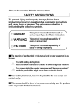
In this manual, safety messages are classified as follows:
WARNING
Improper operation may result in serious personal injury or death.
CAUTION
Improper operation may result in slight to medium personal injury
or property damage.
Throughout this manual we use the following two illustrations to make you
aware of safety considerations:
Identifies potential hazards under certain conditions.
Read the message and follow the instructions carefully.
Identifies shock hazards under certain conditions.
Particular attention should be directed because dangerous voltage may be
present.
Keep operating instructions handy for quick reference.
Read this manual carefully to maximize the performance of SV-iG5A series
inverter and ensure its safe use.
WARNING
Do not remove the cover while power is applied or the unit is in
operation.
Otherwise, electric shock could occur.
Do not run the inverter with the front cover removed.
Otherwise, you may get an electric shock due to high voltage terminals or
charged capacitor exposure.
Do not remove the cover except for periodic inspections or wiring, even
if the input power is not applied.
Otherwise, you may access the charged circuits and get an electric shock.
i
SAFETY INSTRUCTIONS
Wiring and periodic inspections should be performed at least 10 minutes
after disconnecting the input power and after checking the DC link
voltage is discharged with a meter (below DC 30V).
Otherwise, you may get an electric shock.
Operate the switches with dry hands.
Otherwise, you may get an electric shock.
Do not use the cable when its insulating tube is damaged.
Otherwise, you may get an electric shock.
Do not subject the cables to scratches, excessive stress, heavy loads or
pinching.
Otherwise, you may get an electric shock.
CAUTION
Install the inverter on a non-flammable surface. Do not place flammable
material nearby.
Otherwise, fire could occur.
Disconnect the input power if the inverter gets damaged.
Otherwise, it could result in a secondary accident and fire.
After the input power is applied or removed, the inverter will remain hot
for a couple of minutes.
Otherwise, you may get bodily injuries such as skin-burn or damage.
Do not apply power to a damaged inverter or to an inverter with parts
missing even if the installation is complete.
Otherwise, electric shock could occur.
Do not allow lint, paper, wood chips, dust, metallic chips or other foreign
matter into the drive.
Otherwise, fire or accident could occur.
ii
SAFETY INSTRUCTIONS
OPERATING PRECAUTIONS
Environment
(1) Handling and installation
Handle according to the weight of the product.
Do not stack the inverter boxes higher than the number recommended.
Install according to instructions specified in this manual.
Do not open the cover during delivery.
Do not place heavy items on the inverter.
Check the inverter mounting orientation is correct.
Do not drop the inverter, or subject it to impact.
Follow your national electrical code for grounding. Recommended
Ground impedance for 400V class below 10 ohm.
iG5A series contains ESD (Electrostatic Discharge) sensitive parts. Take
protective measures against ESD before touching the pcb for inspection
or installation.
Use the inverter under the following environmental conditions:
Surrounding
temperature
Relative humidity
Storage temperature
Location
Altitude, Vibration
Atmospheric
pressure
- 10 ~ 50 ℃ (non-freezing)
90% RH or less (non-condensing)
- 20 ~ 65 ℃
Protected from corrosive gas,
combustible gas, oil mist or dust
Max. 1,000m above sea level, Max.
5.9m/sec2 (0.6G) or less
70 ~ 106 kPa
(2) Wiring
Do not connect a power factor correction capacitor, surge suppressor, or
RFI filter to the output of the inverter.
The connection orientation of the output cables U, V, W to the motor will
affect the direction of rotation of the motor.
Incorrect terminal wiring could result in the equipment damage.
Reversing the polarity (+/-) of the terminals could damage the inverter.
Only authorized personnel familiar with LS inverter should perform wiring
and inspections.
Always install the inverter before wiring. Otherwise, you may get an
electric shock or have bodily injury.
(3) Trial run
Check all parameters during operation. Changing parameter values
might be required depending on the load.
Always apply permissible range of voltage to the each terminal as
indicated in this manual. Otherwise, it could lead to inverter damage.
iii
SAFETY INSTRUCTIONS
(4) Operation precautions
When the Auto restart function is selected, stay away from the equipment
as a motor will restart suddenly after an alarm stop.
The Stop key on the keypad is valid only when the appropriate function
setting has been made. Prepare an emergency stop switch separately.
If an alarm reset is made with the reference signal present, a sudden
start will occur. Check that the reference signal is turned off in advance.
Otherwise an accident could occur.
Do not modify or alter anything inside the inverter.
Motor might not be protected by electronic thermal function of inverter.
Do not use a magnetic contactor on the inverter input for frequent
starting/stopping of the inverter.
Use a noise filter to reduce the effect of electromagnetic interference.
Otherwise nearby electronic equipment may be affected.
In case of input voltage unbalance, install AC reactor. Power Factor
capacitors and generators may become overheated and damaged due to
potential high frequency noise transmitted from inverter.
Use an insulation-rectified motor or take measures to suppress the micro
surge voltage when driving 400V class motor with inverter. A micro surge
voltage attributable to wiring constant is generated at motor terminals,
and may deteriorate insulation and damage motor.
Before operating unit and prior to user programming, reset user
parameters to default settings.
Inverter can easily be set to high-speed operations, Verify capability of
motor or machinery prior to operating unit.
Stopping torque is not produced when using the DC-Break function.
Install separate equipment when stopping torque is needed.
(5) Fault prevention precautions
Provide a safety backup such as an emergency brake which will prevent
the machine and equipment from hazardous conditions if the inverter
fails.
(6) Maintenance, inspection and parts replacement
Do not conduct a mega (insulation resistance) test on the control circuit
of the inverter.
Refer to Chapter 7 for periodic inspection (parts replacement).
(7) Disposal
Handle the inverter as an industrial waste when disposing of it.
(8) General instructions
Many of the diagrams and drawings in this instruction manual show the
inverter without a circuit breaker, a cover or partially open. Never run the
inverter like this. Always place the cover with circuit breakers and follow this
instruction manual when operating the inverter.
iv
SAFETY INSTRUCTIONS
Important User Information
The purpose of this manual is to provide the user with the necessary
information to install, program, start up and maintain the SV-iG5A series inverter.
To assure successful installation and operation, the material presented must be
thoroughly read and understood before proceeding.
This manual containsE
Chapter
1
2
3
4
5
6
7
Title
Basic
information &
precautions
Installation &
Wiring
Basic
configuration
Programming
keypad & Basic
operation
Function list
Control block
diagram
Troubleshooting
& maintenance
Specifications &
Option
8
Description
Provides general information and precautions for
safe use of the SV-iG5A series inverter.
Provides instructions on how to install and wiring
for power source & signal terminal of SV-iG5A
inverter.
Describes how to connect the optional peripheral
devices to the inverter.
Illustrates keypad features and display & Provides
instructions for quick start of the inverter.
Parameter values are listed.
Shows control flow to help users easily understand
operation mode.
Defines the various inverter faults and the
appropriate action to take as well as general
troubleshooting information.
Gives information on Input/Output rating, control
type and more details of the SV-iG5A inverter.
Explains options including Remote keypad,
Conduit, EMC filter, DB resistor, DeviceNet
Module.
v
TABLE OF CONTENTS
Table of Contents
CHAPTER 1 -
Basic information & precautions ....................................................................... 1-1
1.1 Important precautions .................................................................................................... 1-1
1.2 Product Details............................................................................................................... 1-2
1.3 Product assembling & disassembling ............................................................................. 1-3
CHAPTER 2 -
Installation & Wiring ........................................................................................... 2-1
2.1 Installation precautions .................................................................................................. 2-1
2.2 Dimensions .................................................................................................................... 2-3
2.3 Terminal wiring ............................................................................................................... 2-5
2.4 Specifications for power terminal block wiring ................................................................ 2-6
2.5 Control terminal specification ......................................................................................... 2-9
2.6 PNP/NPN selection and connector for communication option ...................................... 2-11
CHAPTER 3 -
Basic configuration ............................................................................................ 3-1
3.1 Connection of peripheral devices to the inverter............................................................. 3-1
3.2 Recommended MCCB ................................................................................................... 3-2
3.3 Recommendable Fuse, Reactors ................................................................................... 3-2
CHAPTER 4 -
Programming Keypad & Basic operation ......................................................... 4-1
4.1 Keypad features ............................................................................................................. 4-1
4.2 Alpha-numeric view on the LED keypad ......................................................................... 4-2
4.3 Moving to other groups .................................................................................................. 4-3
4.4 How to change the codes in a group .............................................................................. 4-5
4.5 Parameter setting ........................................................................................................... 4-7
4.6 Monitoring of operation status ...................................................................................... 4-10
4.7 Frequency Setting and Basic Operation ....................................................................... 4-13
CHAPTER 5 -
Function list ........................................................................................................ 5-1
CHAPTER 6 -
CONTROL BLOCK DIAGRAM ............................................................................ 6-1
6.1 Frequency setting .......................................................................................................... 6-2
6.2 Drive command setting .................................................................................................. 6-4
6.3 Accel/Decel setting and V/F control ................................................................................ 6-5
CHAPTER 7 -
Troubleshooting & Maintenance ....................................................................... 7-1
7.1 Protective functions. ....................................................................................................... 7-1
7.2 Fault remedy .................................................................................................................. 7-3
7.3 Precautions for maintenance and inspection .................................................................. 7-6
7.4 Check points .................................................................................................................. 7-6
7.5 Part replacements .......................................................................................................... 7-6
CHAPTER 8 -
Specifications ..................................................................................................... 8-1
8.1 Technical data ................................................................................................................ 8-1
8.2 Temperature Derating Information .................................................................................. 8-3
vi
TABLE OF CONTENTS
8.3 Remote option ................................................................................................................ 8-4
8.4 Conduit Kit ...................................................................................................................... 8-6
8.5 Braking resistor .............................................................................................................. 8-6
8.6 Field bus Communication Module ................................................................................... 8-7
DECLARATION OF CONFORMITY.................................................................................................... I
Appendix A : European Standards ............................................................................................ I
Appendix B : Safe Disable Input Functions .............................................................................. II
vii
CHAPTER 1. BASIC INFORMATION & PRECAUTIONS
CHAPTER 1 - BASIC INFORMATION & PRECAUTIONS
1.1 Important precautions
Unpacking
and
inspection
Inspect the inverter for any damage that may have occurred
during shipping. To verify the inverter unit is the correct one for
the application you need, check the inverter type, output ratings
on the nameplate and the inverter is intact.
Inverter Type
Input power rating
Output Power Rating
Rated output current, frequency
Inverter Capacity (kVA)
Bar Code and Serial Number
SV
004
Motor rating
LS Inverter
004
iG5A
Series
Name
-
4
EN/ENC
Input power
Keypad
0.4 [kW]
008 0.75 [kW]
015
1.5 [kW]
022
2.2 [kW]
040
4.0 [kW]
iG5A
4
E
N
General
I/O
E
N
C
FieldBus
Module
Three Phase
380~480[V]
Accessories
If you have found any discrepancy, damage, etc., contact your sales
representative.
Preparation Instruments and parts to be prepared depend on how the inverter is
operated. Prepare equipment and parts as necessary.
s of
instruments
and parts
required for
operation
Installation To operate the inverter with high performance for a long time, install
the inverter in a proper place in the correct direction and with proper
clearances
Connect the power supply, motor and operation signals (control
Wiring
signals) to the terminal block. Note that incorrect connection may
damage the inverter and peripheral devices
1-1
CHAPTER 1. BASIC INFORMATION & PRECAUTIONS
1.2 Product Details
Appearance
Status LED
Display
RUN Button
Top Cover :
Removed when
wiring
STOP/RESET
Button
ENT Button
Inverter
Nameplate
EMC Filter
Inside view after front cover is removed
Refer to “1.3 front cover removal” for details.
4-Way button for
parameter setting
NPN, PNP
(Up/Down/Left/Right)
Select Switch
Control terminal
Inverter Ground
Terminal
AC Source input
Terminal
Cooling fan
Power terminal
1-2
CHAPTER 1. BASIC INFORMATION & PRECAUTIONS
1.3 Product assembling & disassembling
To remove the front cover: Release the screw and then press the both
indented sides of the cover lightly and pull up.
Release Screw
Press this part lightly and
pull it up.
To change the inverter fan: Press the both sides of bottom cover lightly
and pull out to your side.
Press this part and
pull out.
1-3
CHAPTER 1. BASIC INFORMATION & PRECAUTIONS
1-4
CHAPTER 2. INSTALLATION & WIRING
CHAPTER 2 - INSTALLATION & WIRING
2.1 Installation precautions
CAUTION
Handle the inverter with care to prevent damage to the plastic components.
Do not hold the inverter by the front cover. It may fall off.
Install the inverter in a place where it is immune to vibration (5.9 m/s2 or less).
Install in a location where temperature is within the permissible range (10~50°C).
<Ambient Temperature Checking Location>
The inverter will be very hot during operation. Install it on a non-combustible
surface.
Mount the inverter on a flat, vertical and level surface. Inverter orientation
must be vertical (top up) for proper heat dissipation. Also leave sufficient
clearances around the inverter.
Min. 10cm
Min.
Min.
5cm
5cm
Min. 10cm
Leave space enough to
allow cooled air flowing
easily between wiring
duct and the unit
Cooling air
Ventilating fan
Protect from moisture and direct sunlight.
Do not install the inverter in any environment where it is exposed to water
drops, oil mist, dust, etc. Install the inverter in a clean place or inside a
“totally enclosed” panel any suspended matter is not entered.
2-1
CHAPTER 2. INSTALLATION & WIRING
When two or more inverters are installed or a cooling fan is mounted in a
panel, the inverters and fan must be installed in proper positions with extreme
care to keep the ambient temperature below the permissible range.
Installed the inverter using screws or bolts to insure the inverter is firmly
fastened.
< When two or more units are installed >
Heat
: NG
< Where the ventilation fan is installed >
CAUTION
Take caution on proper heat ventilation when installing inverters and fans
in a panel.
2-2
CHAPTER 2. INSTALLATION & WIRING
2.2 Dimensions
SV004iG5A-4EN / SV008iG5A-4EN
SV015iG5A-4EN
2-3
CHAPTER 2. INSTALLATION & WIRING
SV022iG5A-4EN / SV040iG5A-4EN
Inverter
SV004IG5A-4
SV008IG5A-4
SV015IG5A-4
SV022IG5A-4
SV040IG5A-4
2-4
W
W1
H
H1
D
[mm] [mm] [mm] [mm] [mm]
75
61
175 160.5 164
75
61
175 160.5 164
110
80
175 160.5 164
150
90
175 160.5 190
150
90
175 160.5 190
Φ
5.5
5.5
5.5
5.5
5.5
A
A1
B
[Kg]
[mm] [mm] [mm]
6.5
6
5.5 1.13
6.5
6
5.5 1.14
7
14
5.5 1.54
7
29
5.5 2.32
7
29
5.5 2.37
CHAPTER 2. INSTALLATION & WIRING
2.3 Terminal wiring
* Control terminal wiring
T/M
Description
MO
MG
24
P1
P2
CM
P3
P4
P5
CM
P6
VR
V1
I
AM
Multi-function open collector output
MO Common
24V output
MF input terminal FX: Forward run
(factory setting) RX: Reverse run
Input signal common
BX: Emergency stop
MF input terminal
RST: Trip reset
(factory setting)
JOG: Jog operation
Input signal common
MF input terminal Multi-step freq.-Low
12V power supply for potentiometer
Freq. Setting Voltage signal input: 0~10V
Freq. Setting Current signal input: 0~20mA
Multi-function analog output signal: 0~10V
SA
SB
SC
Safety Input A Open : Coast to stop(Note1)
Safety Input B Closed : Normal operation
Power supply for Safety Function (24Vdc)
3A
3B
3C
S+
S-
Multi-function
relay output
terminal
A contact output
B contact output
A/B contact common
RS485 communication terminal
Note1) Disconnect wire jumper between SA, SB and SC
when using safety input
※ For connection to Remote Option or parameter copying
2-5
CHAPTER 2. INSTALLATION & WIRING
* Power terminal wiring
2.4 Specifications for power terminal block wiring
Standard 0.4 ~ 1.5kW terminal block (L1’=R, L2’=S, L3’=T)
Standard 2.2 ~ 4.0kW terminal block (L1’=R, L2’=S, L3’=T)
SV004iG5A-4EN
SV008iG5A-4EN
SV015iG5A-4EN
SV022iG5A-4EN
SV040iG5A-4EN
L1,L2,L3 Size U,V,W Size Ground Size
Terminal
mm2 AWG mm2 AWG mm2 AWG Screw Size
2
14
2
14
2
14
M3.5
2
14
2
14
2
14
M3.5
2
14
2
14
2
14
M4
2
14
2
14
2
14
M4
2
14
2
14
2
14
M4
Screw Torque
(Kgf.cm)/lb-in
10/8.7
10/8.7
15/13
15/13
15/13
* Strip the sheaths of the wire insulation 7mm when a ring terminal is not used for
power connection.
7.0mm
2-6
CHAPTER 2. INSTALLATION & WIRING
CAUTION
Apply the rated torque to terminal screws. Loosen screws can cause of
short circuit and malfunction. Tightening the screw too much can damage
the terminals and cause short circuit and malfunction.
Use copper wires only with 600V, 75℃ ratings for wiring.
Make sure the input power is off before wiring.
When power supply is switched off following operation, wait at least 10
minutes after LED keypad display is off before you start working on it.
Applying input power supply to the output terminals U, V and W causes
internal inverter damage.
Use ring terminals with insulated caps when wiring the input power and
motor wiring.
Do not leave wire fragments inside the inverter. Wire fragments can cause
faults, breakdowns and malfunctions.
When more than one motor is connected to one inverter, total wire length
should be less than 100m (328ft). Do not use a 3-wire cable for long
distances. Due to increased leakage capacitance between wires, overcurrent protective feature may operate or equipment connected to the
output side may malfunction. In case of long wire length, it should be
required to lower carrier frequency or use Micro Surge Filter.
Length between Inverter and
More than
Up to 50m
Up to 100m
Motor
100m
Less than
Less than
Less than
Allowable Carrier Frequency
15kHz
5kHz
2.5kHz
Never short B1 and B2 terminals. Shorting terminals may cause internal
inverter damage.
Do not install a power factor capacitor, surge suppressor or RFI filters in
the output side of the inverter. Doing so may damage these components.
[WARNING]
Power supply must be connected to the R, S, and T Terminals.
Connecting it to the U, V, W terminals causes internal damages to the inverter.
Arranging the phase sequence is not necessary.
Motor should be connected to the U, V, and W Terminals.
If the forward command (FX) is on, the motor should rotate counter clockwise
when viewed from the load side of the motor. If the motor rotates in the reverse,
switch the U and V terminals.
2-7
CHAPTER 2. INSTALLATION & WIRING
WARNING
Be sure to ground the drive ground terminal. (Ground to 10Ω or less)
Improper equipment grounding could result in death or serious injury by
contacting ungrounded electrical equipment.
Ground
Terminal B
Ground
Terminal A
Note
Grounding procedure
1) Use Terminal A to earth.
2) For using Terminal B :
Remove the front cover and release the input wire(R,S,T).
Connect the grounding wire to the ground terminal through the opening for
ground terminal as shown above. Enter the screw driver from vertical to the
terminal and secure the screw tightly.
Note
Grounding work guidance
Inverter
capacity
0.4~4.0 kW
2-8
400V Class
Ground Terminal
Wire size
Terminal screw Ground method
Terminal A
2.0~14.0 mm2
M5
Terminal B
2.0 mm2
M3
Special Type 3
CHAPTER 2. INSTALLATION & WIRING
2.5 Control terminal specification
Wire size[mm2]
Screw Torque
T/M Terminal Description single Strand
size
[Nm]
wire
ed
P1~ Multi-function input T/M
1.0
1.5
M2.6
0.4
P6 1-6
CM Common Terminal
VR
V1
I
AM
MO
MG
24
SA
SB
SC
3A
3B
3C
Power supply for
external potentiometer
Input terminal for
Voltage operation
Input terminal for
Current operation
Multi-function analog
output terminal
Multi-function terminal
for open collector
Ground terminal for
external power supply
24V External Power
Supply
Safety input command
1
Safety input command
2
Power supply for safety input command
Multi-function relay
output A contact
Multi-function relay
output B contact
Common for Multifunction relays
Specification
1.0
1.5
M2.6
0.4
1.0
1.5
M2.6
0.4
1.0
1.5
M2.6
0.4
1.0
1.5
M2.6
0.4
1.0
1.5
M2.6
0.4
1.0
1.5
M2.6
0.4
1.0
1.5
M2.6
0.4
1.0
1.5
M2.6
0.4
1.0
1.5
M2.6
0.4
1.0
1.5
M2.6
0.4
Max output current:
100mA
Open : Coast to stop
safety input
Closed : Normal
operation
1.0
1.5
M2.6
0.4
+24Vdc, Max. 10mA
1.0
1.5
M2.6
0.4
Below AC 250V, 1A
1.0
1.5
M2.6
0.4
Below DC 30V, 1A
1.0
1.5
M2.6
0.4
Output voltage: 12V
Max output current: 10mA
Potentiometer:1 ~ 5kohm
Max input voltage:
-10V ~ +10V input
0 ~ 20mA input
Internal resistor: 250 ohm
Max output voltage: 11[V]
Max output current: 10mA
Below DC 26V,100mA
2-9
CHAPTER 2. INSTALLATION & WIRING
Note 1) Tie the control wires more than 15cm away from the control terminals.
Otherwise, it interferes front cover reinstallation
Note 2) Use Copper wires rated 600V, 75 ℃ and higher.
Note 3) Use the recommended tightening torque when securing terminal screws.
Note
1) When you use external power supply (24V) for multi-function input terminal
(P1~P6), terminals will be active above 12V level. Take caution not to drop
the voltage below 12V.
2) When you use safety function, disconnect wire jumper between SA, SB and
SC
3) Wire the control terminal only after terminals have been properly grounded
and main circuit wiring is complete.
When control terminal wiring, use shielded twisted-pair cables as indicated to
prevent operating faults. Improper wiring practices could result in drive or
equipment malfunction due to electrical interference.
Blade width of 2.5mm or less
Strip length about 5.5mm
2-10
CHAPTER 2. INSTALLATION & WIRING
2.6 PNP/NPN selection and connector for communication option
1. When using DC 24V inside inverter [NPN]
SW S8
NPN
S8
DC 24 V
SW S8
CM
R
P1
CPU
R
R
CM
(inside inverter)
CM
2. When using external DC 24V [PNP]
SW S8
PNP
S8
DC 24 V
DC24V
CM
R
P1
R
CPU
R
CM
( inside inverter)
inverter)
CM
2-11
CHAPTER 2. INSTALLATION & WIRING
2-12
CHAPTER 3. BASIC CONFIGURATION
CHAPTER 3 - BASIC CONFIGURATION
3.1 Connection of peripheral devices to the inverter
The following devices are required to operate the inverter. Proper peripheral
devices must be selected and correct connections made to ensure proper
operation. An incorrectly applied or installed inverter can result in system
malfunction or reduction in product life as well as component damage. You must
read and understand this manual thoroughly before proceeding.
AC Source
Supply
Use the power supply within the
permissible range of inverter input
power rating (Refer to Page 8-1).
MCCB or Earth
leakage circuit
breaker (ELB)
Select circuit breakers with care. A
large inrush current may flow in the
inverter at power on.
Magnetic
Contactor
Install it if necessary. When
installed, do not use it for the
purpose of starting or stopping.
Otherwise, it could lead to
reduction in product life.
AC Reactors
The AC reactors must be used
when the power factor is to be
improved or the inverter is installed
near a large power supply system
(more than 10 times of inverter
capacity and wiring distance within
10m).
Installation and
wiring
To operate the inverter with high
performance for a long time, install
the inverter in a proper place in the
correct direction and with proper
clearances. Incorrect terminal
wiring could result in the equipment
damage.
To motor
Do not connect a power factor
capacitor, surge suppressor or
radio noise filter to the output side
of the inverter.
3-1
CHAPTER 3. BASIC CONFIGURATION
3.2 Recommended MCCB
Inverter
Capacity
004iG5A-4
008iG5A-4
015iG5A-4
022iG5A-4
040iG5A-4
MCCB
(LS)
TD125U,EBs33
TD125U,EBs33
TD125U,EBs33
TD125U,EBs33
TD125U,EBs33
MC
GMC-12
GMC-12
GMC-12
GMC-22
GMC-22
Note
The capacity of the MCCB should be 1.5 to 2 times the rated output current of
the drive. Use an MCCB keep the drive from faulting out instead of using
overheat protection (150% for one minute at the rated output current.
3.3 Recommendable Fuse, Reactors
Inverter
Capacity
004iG5A-4
008iG5A-4
015iG5A-4
022iG5A-4
040iG5A-4
AC Input fuse [External Fuse]
Current
Voltage
5A
600 V
10 A
600 V
10 A
600 V
10 A
600 V
20 A
600 V
AC Reactor
DC Reactor
18.0 mH, 1.3A
8.63 mH, 2.8A
4.81 mH, 4.8A
3.23 mH, 7.5A
2.34 mH, 10A
-
Short Circuit Rating
“Suitable For Use ON A Circuit Capable Of Delivering Not More Than
65KA Symmetrical Amperes. 480V drives Volts Maximum,”
Short Circuit FUSE/BREAKER Marking
Use Class H or RK5 UL Listed Input Fuse and UL Listed Breaker Only.
See the table above For the Voltage and Current rating of the fuse and
the breaker
3-2
CHAPTER 3. BASIC CONFIGURATION
3-3
CHAPTER 4. PROGRAMMING KEYPAD & BASIC OPERATION
CHAPTER 4 - PROGRAMMING KEYPAD & BASIC OPERATION
4.1 Keypad features
Display
SET/RUN LED
FWD/REV LED
7 Segment LED
Key
RUN
STOP/RESET
Up/Down
Left/Right
Enter [ENT]
Display
FWD
Lit during forward run
REV
Lit during reverse run
RUN
Lit during Operation
SET
Lit during parameter setting
7 segment
Blinks when a fault occurs
Displays operation status and parameter information
Keys
RUN
STOP/RESET
UP
Down
⊳
Left
Right
ENT
Run command
STOP: Stop command during operation,
RESET: Reset command when fault occurs.
Used to scroll through codes or increase parameter value
Used to scroll through codes or decrease parameter value
Used to jump to other parameter groups or move a cursor to
the left to change the parameter value
Used to jump to other parameter groups or move cursor to the
right to change the parameter value
Used to set the parameter value or save the changed
parameter value
4-1
CHAPTER 4. PROGRAMMING KEYPAD & BASIC OPERATION
4.2 Alpha-numeric view on the LED keypad
4-2
0
A
K
U
1
B
L
V
2
C
M
W
3
D
N
X
4
E
O
Y
5
F
P
Z
6
G
Q
7
H
R
8
I
S
9
J
T
CHAPTER 4. PROGRAMMING KEYPAD & BASIC OPERATION
4.3 Moving to other groups
There are 4 different parameter groups in SV- iG5A series as shown below.
Drive group
FU group 1
FU group 2
I/O group
Drive group
Function group 1
Function group 2
I/O (Input/Output)
group
Basic parameters necessary for the inverter to run.
Parameters such as Target frequency, Accel/Decel
time settable.
Basic function parameters to adjust output frequency
and voltage.
Advanced function parameters to set parameters for
such as PID Operation and second motor operation.
Parameters necessary to make up a sequence using
Multi-function input/output terminal.
Moving to other parameter groups is only available in the first code of each
group as the figure shown below.
Moving to other groups using the Right Moving to other groups using the Left
() key
(⊳) key
*
*
Drive group
Drive group
Function
group 1
I/O group
Function
group 2
Function
group 1
I/O group
Function
group 2
* Target frequency can be set at 0.0 (the 1st code of drive group). Even though the
preset value is 0.0, it is user-settable. The changed frequency will be displayed
after it is changed.
4-3
CHAPTER 4. PROGRAMMING KEYPAD & BASIC OPERATION
How to move to other groups at the 1st code of each group
1
-. The 1st code in Drive group “0.00” will be displayed when AC
input power is applied.
-. Press the right arrow () key once to go to Function group 1.
2
-. The 1st code in Function group 1 “F 0” will be displayed.
-. Press the right arrow () key once to go to Function group 2.
3
-. The 1st code in Function group 2 “H 0” will be displayed.
-. Press the right arrow () key once to go to I/O group.
4
-. The 1st code in I/O group “I 0” will be displayed.
-. Press the right arrow () key once again to return to Drive
group.
5
-. Return to the 1st code in Drive group “0.00”.
♣ If the left arrow key (⊳) is used, the above will be executed in the reverse
order.
How to move to other groups from any codes other than the 1st code
Pressing left or
right arrow key in
any code will
return to first code
of each group.
Drive group
FU group 1
FU group 2
To move from the F 15 to function group 2
1
-. In F 15, press the Left (⊳) or Right arrow () key. Pressing the
key goes to the first code of the group.
2
-. The 1st code in function group 1 “F 0” is displayed.
-. Press the right arrow () key.
3
-. The 1st code in function group 2 “H 0” will be displayed.
4-4
CHAPTER 4. PROGRAMMING KEYPAD & BASIC OPERATION
4.4 How to change the codes in a group
Code change in Drive group
1
2
3
4
Drive group
5
-. In the 1st code in Drive group
“0.00”, press the Up () key
once.
-. The 2nd code in Drive group
“ACC” is displayed.
-. Press the Up () key once.
-. The 3rd code “dEC” in Drive
group is displayed.
-. Keep pressing the Up () key
until the last code appears.
-. The last code in Drive group
“drC” is displayed.
-. Press the Up () key again.
-. Return to the first code of Drive
group.
♣ Use Down () key for the opposite order.
Code jump
When moving from the “F 0” to the “F 15” directly
1
-. Press the Ent () key in “F 0”.
-. 1 (the code number of F1) is
displayed. Use the Up () key to
2
set to 5.
-. “05” is displayed by pressing the
Left (⊳) key once to move the
cursor to the left. The numeral
3
having a cursor is displayed
brighter. In this case, 0 is active.
-. Use the Up () key to set to 1.
FU group 1
-. 15 is set.
4
-. Press the Ent () key once.
-. Moving to F 15 has been
5
complete.
♣ Function group 2 and I/O group are settable with the same setting.
4-5
CHAPTER 4. PROGRAMMING KEYPAD & BASIC OPERATION
Navigating codes in a group
When moving from F 1 to F 15 in Function group 1
1
-. In F 1, continue pressing the Up
() key until F15 is displayed.
2
-. Moving to F15 has been
complete.
♣ The same applies to Function group 2 and I/O
group.
♣Note: Some codes will be skipped in the middle of increment ()/decrement
() for code change. That is because it is programmed that some codes are
intentionally left blank for future use or the codes user does not use are
invisible.
Refer to the Ch.5 for more specific contents
For example, when F24 [High/low frequency limit select] is set to “O (No) ”, F25
[High frequency limit] and F26 [Low frequency limit] are not displayed during
code change. But When F24 is set to “1(Yes)”, F25 and F26 will appear on the
display.
4-6
CHAPTER 4. PROGRAMMING KEYPAD & BASIC OPERATION
4.5 Parameter setting
Changing parameter values in Drive Group
When changing ACC time from 5.0 sec to 16.0 sec
Drive group
1
2
3
4
5
6
7
8
-. In the first code “0.00”, press the Up () key once to go to
the second code.
-. ACC [Accel time] is displayed.
-. Press the Ent key () once.
-. Preset value is 5.0, and the cursor is in the digit 0.
-. Press the Left (⊳) key once to move the cursor to the left.
-. The digit 5 in 5.0 is active. Then press the Up () key
once.
-. The value is increased to 6.0
-. Press the Left (⊳) key to move the cursor to the left.
-. 0.60 is displayed. The first 0 in 0.60 is active.
-. Press the Up () key once.
-. 16.0 is set.
-. Press the Ent () key once.
-. 16.0 is blinking.
-. Press the Ent () key once again to return to the parameter
name.
-. ACC is displayed. Accel time is changed from 5.0 to 16.0
sec.
♣ In step 7, pressing the Left (⊳) or Right () key while 16.0 is blinking will
disable the setting.
Note 1) Pressing the Left (⊳)/ Right () /Up () /Down () key while cursor is
blinking will cancel the parameter value change. Pressing the Enter key () in this
status will enter the value into memory.
4-7
CHAPTER 4. PROGRAMMING KEYPAD & BASIC OPERATION
Frequency setting
When changing run frequency to 30.05 Hz in Drive group
Drive group
1
-. In “0.00”, press the Ent () key once.
2
-. The second decimal 0 becomes active.
-. Press the UP () key until 5 is displayed.
3
-. Press the Left (⊳) key once.
4
-. The first decimal 0 becomes active.
-. Press the Left (⊳) key once.
5
-. Press the Left (⊳) key once.
6
-. Set 3 using UP () key.
7
-. Press the Ent () key.
-. 30.05 is blinking.
-. Press the Ent () key.
8
-. 30.05 is entered into memory.
♣ SV-iG5A display can be extended to 5 digits using left (⊳)/right () keys.
♣ Parameter setting is disabled when pressing other than Enter Key in step 7.
4-8
CHAPTER 4. PROGRAMMING KEYPAD & BASIC OPERATION
Changing parameter value in Input/Output group
When changing the parameter value of F28 from 2 to 5
FU group 1
1
-. In F0, press the Ent () key once.
2
-. Check the present code number.
-. Increase the value to 8 by pressing the Up () key.
3
-. When 8 is set, press the Left (⊳) key once.
4
5
6
7
-. 0 in 08 is active.
-. Increase the value to 2 by pressing the Up () key.
-. 28 is displayed
-. Press the Ent () key once.
-. The parameter number F28 is displayed.
-. Press the Ent () key once to check the set value.
-. The preset value 2 is displayed.
-. Increase the value to 5 using UP key ().
8
-. Press the Ent () key.
9
-. Code number will appear after 5 is blinking. Parameter
change is complete.
-. Press either Left (⊳) or Right () keys.
10
-. Moving to first code of Function group 1 is complete.
♣ The above setting is also applied to change parameter values in function
group 2 and I/O group.
4-9
CHAPTER 4. PROGRAMMING KEYPAD & BASIC OPERATION
4.6 Monitoring of operation status
Output current display
Monitoring output current in Drive group
Drive group
1
-. In [0.0], continue pressing the Up () or Down () key until
[CUr] is displayed.
2
-. Monitoring output current is provided in this parameter.
-. Press the Enter () key once to check the current.
3
-. Present output current is 5 A.
-. Press the Enter () key once to return to the parameter
name.
4
-. Return to the output current monitoring code.
♣ Other parameters in Drive group such as dCL (Inverter DC link voltage) or
vOL (Inverter output voltage) can be monitored via the same method.
4-10
CHAPTER 4. PROGRAMMING KEYPAD & BASIC OPERATION
Fault display
How to monitor fault condition in Drive group
During
Accel
Overcurrent
trip
Current
Frequency
STOP
RESET
Drive group
-. This message appears when an Overcurrent fault occurs.
-. Press the Enter () key or UP/Down key once.
-. The run frequency at the time of fault (30.0) is displayed.
-. Press the Up () key once.
-. The output current at the time of fault is displayed.
-. Press the Up () key once.
-. Operating status is displayed. A fault occurred during
acceleration.
-. Press the STOP/RST key once.
1
2
3
4
-. A fault condition is cleared and “nOn” is displayed.
5
When more than one fault occurs at the same time
-. Maximum three faults information is
displayed as shown left.
Motor
overheat
Over
voltage
Over
current
Drive group
4-11
CHAPTER 4. PROGRAMMING KEYPAD & BASIC OPERATION
Parameter initialize
How to initialize parameters of all four groups in H93
FU group 2
1
2
3
4
5
6
7
-. In H0, press the Enter () key once.
-. Code number of H0 is displayed.
-. Increase the value to 3 by pressing the Up () key.
-. In 3, press the Left (⊳) key once to move the cursor to the
left.
-. 03 is displayed. 0 in 03 is active.
-. Increase the value to 9 by pressing the Up () key.
-. 93 is set.
-. Press the Enter () key once.
-. The parameter number is displayed.
-. Press the Enter () key once.
-. Present setting is 0.
-. Press the Up () key once to set to 1 to activate parameter
initialize.
8
-. Press the Enter () key once.
9
-. Return to the parameter number after blinking. Parameter
initialize has been complete.
-. Press the either Left (⊳) or Right () key.
10
-. Return to H0.
4-12
CHAPTER 4. PROGRAMMING KEYPAD & BASIC OPERATION
4.7 Frequency Setting and Basic Operation
☞ Caution : The following instructions are given based on the fact that all
parameters are set to factory defaults. Results could be different if parameter
values are changed. In this case, initialize parameter values (see page 10-21)
back to factory defaults and follow the instructions below.
Frequency Setting via keypad & operating via terminals
1
-. Apply AC input power to the inverter.
2
-. When 0.00 appears, press the Ent () key once.
3
-. The second digit in 0.00 is lit as shown right.
-. Press the Left (⊳) key three times.
4
-. 00.00 is displayed and the first 0 is lit.
-. Press the Up () key.
5
-. 10.00 is set. Press the Ent () key once.
-. 10.00 is blinking. Press the Ent () key once.
6
-. Run frequency is set to 10.00 Hz when the blinking stops.
-. Turn on the switch between P1 (FX) and CM terminals.
7
-. RUN lamp begins to blink with FWD (Forward Run) lit and
accelerating frequency is displayed on the LED.
-. When target run frequency 10Hz is reached, 10.00 is
displayed.
-. Turn off the switch between P1 (FX) and CM terminals.
8
-. RUN lamp begins to blink and decelerating frequency is
displayed on the LED.
-. When run frequency is reached to 0Hz, Run and FWD lamp
turn off and 10.00 is displayed.
3P
AC
Input
R
S
T
U
V
W
Motor
10 Hz
Freq.
G
P1(FX)
CM
Wiring
P1(FX)-CM
ON
OFF
Operating pattern
4-13
CHAPTER 4. PROGRAMMING KEYPAD & BASIC OPERATION
Frequency Setting via potentiometer & operating via terminals
1
-. Apply AC input power to the inverter.
2
-. When 0.00 appears Press the Up () key four times.
3
-. Frq is displayed. Frequency setting mode is selectable.
-. Press the Ent () key once.
4
-. Present setting method is set to 0 (frequency setting via
keypad).
-. Press the Up () key three times.
5
-. After 3 (Frequency setting via potentiometer) is set, press the
Ent () key once.
6
-. Frq is redisplayed after 3 stops blinking.
-. Press the Down () key four times.
-. Turn the potentiometer to set to 10.00 Hz in either Max or Min
direction.
7
-. Turn on the switch between P1 (FX) and CM (See Wiring below).
-. RUN lamp begins to blink with FWD lamp lit and the
accelerating frequency is displayed on the LED.
-. When run frequency 10Hz is reached, the value is displayed as
shown left.
-. Turn off the switch between P1 (FX) and CM terminals.
8
-. RUN lamp begins to blink and decelerating frequency is
displayed on the LED.
-. When run frequency is reached to 0Hz, Run and FWD lamp
turn off and 10.00 is displayed.
3P AC
input
R
S
T
U
V
W
Motor
10 Hz
Freq.
P1(FX)
G
CM
P1(FX)-CM
ON
VR
V1
CM
Wiring
4-14
Operating pattern
OFF
CHAPTER 4. PROGRAMMING KEYPAD & BASIC OPERATION
Frequency setting via potentiometer & operating via the Run key
1
-. Apply AC input power to the inverter.
2
-. When 0.00 is displayed, press the Up () key three times.
3
4
5
6
7
8
9
10
11
12
-. “drv” is displayed. Operating method is selectable.
-. Press the Ent () key.
-. Check the present operating method (“1”: Run via control terminal).
-. Down () key once.
-. After setting “0”, press the Ent () key. When 0 is blinking, press
the Ent again.
-. “drv” is displayed after “0” is blinking. Operation method is set via
the Run key on the keypad. -. Press the Up () key once.
-. Different frequency setting method is selectable.
-. Press the Ent () key.
-. Check the present frequency setting method (“0” is run via keypad).
-. Press the Up () key three times.
-. After checking “3” (frequency setting via potentiometer), press the
Ent () key.
-. “Frq” is displayed after “3” is blinking. Frequency setting is set via
the potentiometer on the keypad.
-. Press the Down () key four times.
-. Turn the potentiometer to set to 10.0 Hz in either Max or Min
direction.
-. Press the Run key on the keypad.
-. RUN lamp begins to blink with FWD lamp lit and accelerating
frequency is displayed on the LED.
-. When run frequency 10Hz is reached, 10.00 is displayed as shown
left.
-. Press the STOP/RST key.
-. RUN lamp begins to blink and decelerating frequency is displayed
on the LED.
-. When run frequency is reached to 0Hz, Run and FWD lamp turn off
and 10.00 is displayed.
R
S
T
U
V
W
Motor
10 Hz
Freq.
Keypad
Run key
G
VR
V1
CM
Wiring
STOP/RST key
Operating pattern
4-15
CHAPTER 4. PROGRAMMING KEYPAD & BASIC OPERATION
4-16
CHAPTER 5. FUNCTION LIST
CHAPTER 5 - FUNCTION LIST
Drive Group
LED
Address for
display communication
0.00
A100
ACC
dEC
A101
A102
Parameter
name
Min/Max
range
Frequency
command
This parameter sets the frequency that the
inverter is commanded to output.
During Stop: Frequency Command
0 ~ 400
During Run: Output Frequency
[Hz]
During Multi-step operation:
Multi-step frequency 0.
It cannot be set greater than F21.
Description
Accel time 0 ~ 6000 During Multi-Accel/Decel operation, this
[Sec] parameter serves as Accel/Decel time 0.
Decel time
0 Run/Stop via Run/Stop key on the kpd
FX: Motor forward run
1
Terminal RX: Motor reverse run
operation FX: Run/Stop enable
drv
A103
Drive mode
0~4
2
RX: Reverse rotation select
3 RS485 communication
4 Field bus communication1)
0
Keypad setting 1
Digital
1
Keypad setting 2
2
V1 1: -10 ~ +10 [V]
3
V1 2: 0 ~ +10 [V]
4
I: 0 ~ 20 [mA]
Analog
Frequency
Terminal V1 setting 1 +
5
Frq
A104
setting
0 ~ 10
Terminal I
method
Terminal V1 setting 2+
6
Terminal I
7 RS485 communication
8 Digital Volume
9 Field bus communication1)
10 Pulse train1)
Multi-Step
Sets Multi-Step frequency 1 during MultiSt1
A105
frequency 1
step operation.
Multi-Step 0 ~ 400 Sets Multi-Step frequency 2 during MultiSt2
A106
frequency 2
[Hz] step operation.
Multi-Step
Sets Multi-Step frequency 3 during MultiSt3
A107
frequency 3
step operation.
CUr
A108
Output current
Displays the output current to the motor.
rPM
A109
Motor RPM
Displays the number of Motor RPM.
1)
: This function can be available with iG5A Communication Option Module.
Factory
Adj.
defaults during run
0.00
O
5.0
10.0
O
O
1
X
0
X
10.00
O
20.00
O
30.00
O
-
-
5-1
CHAPTER 5. FUNCTION LIST
Drive Group
LED
Address for
display communication
dCL
A10A
Parameter
name
Inverter DC
link voltage
vOL
A10B
User display
select
nOn
A10C
Fault Display
drC
A10D
Direction of
motor rotation
select
drv21)
A10E
Drive mode 2
Min/Max
range
Description
Displays DC link voltage inside the inverter
Factory
Adj.
defaults during run
-
This parameter displays the item
selected at H73- [Monitoring item select].
vOL Output voltage
vOL
POr Output power
tOr Torque
Displays the types of faults, frequency
and operating status at the time of the
fault
Sets the direction of motor rotation when
drv - [Drive mode] is set to either 0 or 1.
F, r
F
F Forward
r Reverse
Run/Stop via Run/Stop key on the
0
keypad
FX: Motor forward run
1
Terminal RX: Motor reverse run
0~3
1
operation FX: Run/Stop enable
2
RX: Reverse rotation select
-
-
-
O
X
3 RS485 communication
4 Field bus communication2)
0
Keypad setting 1
Digital
1
Keypad setting 2
2
V1 1: -10 ~ +10 [V]
3
V1 2: 0 ~ +10 [V]
4
Terminal I: 0 ~ 20 [mA]
Analog
Frequency
Terminal V1 setting 1 +
5
Frq21)
A10F
setting
0~7
Terminal I
0
X
method 2
Terminal V1 setting 2+
6
Terminal I
7 RS-485 communication
8 Digital Volume
9 Field bus communication2)
10 Pulse train2)
1)
: Only displayed when one of the Multi-function input terminals 1-8 [I17~I24] is set to “22”.
2)
: This function can be available with iG5A Communication Option Module.
5-2
CHAPTER 5. FUNCTION LIST
Drive Group
LED
Address for
display communication
Parameter
name
Min/Max
range
Description
If H58 is 0, it is expressed as a [Hz]
unit.
0~400
If H58 is 1, it is expressed as a [%]
PID control
[Hz] or
unit.
rEF1)
A110
standard
0~100
In [Hz] unit, you can’t set Max.
value setting
[%]
frequency more than (F21).
In [%] unit, 100% means Max.
frequency.
It indicates a feedback amount in PID
control.
PID control
Fbk1)
If H58 is 0, it is expressed as a [Hz]
A111
feedback
unit.
amount
If H58 is 1, it is expressed as a [%]
unit.
1)
: It is indicated when H49(PID control selection) is 1.
Factory
Adj.
defaults during run
0.00
0
-
-
5-3
CHAPTER 5. FUNCTION LIST
Function group 1
Address for
LED
Parameter Min/Max
communicadisplay
name
range
tion
F0
A200
Jump code
0 ~ 71
F1
A201
Forward/
Reverse run
disable
0~2
F2
A202
Accel
pattern
Decel
pattern
0~1
F3
A203
Stop mode
select
F 81)
A208
DC Brake
0.1 ~ 60
start
[Hz]
frequency
F9
A209
DC Brake
wait time
0 ~ 60
[sec]
F10
A20A
DC Brake
voltage
0 ~ 200
[%]
F11
A20B
DC Brake
time
0 ~ 60
[sec]
F12
A20C
F13
A20D
F14
A20E
F20
A214
1)
0~3
DC Brake 0 ~ 200
start voltage [%]
0 ~ 60
[sec]
Time for
0 ~ 60
magnetizing
[sec]
a moto]
0 ~ 400
[Hz]
0 Decelerate to stop
1 DC brake to stop
2 Free run to stop
3 Power Braking stop
This parameter sets DC brake start
frequency.
It cannot be set below F23 - [Start
frequency].
When DC brake frequency is reached,
the inverter holds the output for the
setting time before starting DC brake.
This parameter sets the amount of DC
voltage applied to a motor.
It is set in percent of H33 – [Motor rated
current].
This parameter sets the time taken to
apply DC current to a motor while motor
is at a stop.
This parameter sets the amount of DC
voltage before a motor starts to run.
It is set in percent of H33 – [Motor rated
current].
DC voltage is applied to the motor for
DC Brake start time before motor
accelerates.
This parameter applies the current to a
motor for the set time before motor
accelerates during Sensorless vector
control.
This parameter sets the frequency for
Jog operation.
It cannot be set above F21 – [Max
frequency].
: Only displayed when F 4 is set to 1 (DC brake to stop).
5-4
1
O
0
X
0
X
0
X
5.00
X
0.1
X
50
X
1.0
X
50
X
0
X
0.1
X
10.00
O
1 S-curve
A204
Jog
frequency
Sets the parameter code number to
jump.
0 Fwd and rev run enable
1 Forward run disable
2 Reverse run disable
Factory
Adj.
defaults during run
0 Linear
F4
DC Brake
start time
Description
CHAPTER 5. FUNCTION LIST
Function group 1
Address for
LED
Parameter Min/Max
communica
display
name
range
tion
F21 1)
A215
F22
A216
F23
A217
F24
A218
F25 2)
A219
F26
A21A
F27
A21B
F28
A21C
F29
A21D
Description
This parameter sets the highest
frequency the inverter can output.
It is frequency reference for
Max
40 ~ 400 Accel/Decel (See H70)
frequency
[Hz]
Caution
Factory
Adj.
defaults during run
60.00
Any frequency cannot be set above
Max frequency except Base
frequency
The inverter outputs its rated voltage
Base
30 ~ 400
to the motor at this frequency (see
60.00
frequency
[Hz]
motor nameplate).
The inverter starts to output its
Start
0.1 ~ 10
voltage at this frequency.
0.50
[Hz]
frequency
It is the frequency low limit.
Frequency
This parameter sets high and low
high/low
0~1
0
limit of run frequency.
limit select
This parameter sets high limit of the
Frequency 0 ~ 400 run frequency.
60.00
high limit
[Hz] It cannot be set above F21 – [Max
frequency].
This parameter sets low limit of the
run frequency.
Frequency 0.1 ~ 400
It cannot be set above F25 0.50
low limit
[Hz]
[Frequency high limit] and below
F23 – [Start frequency].
Torque
0
Manual torque boost
Boost
0~1
0
1
Auto torque boost
select
This parameter sets the amount of
Torque
torque boost applied to a motor
boost in
during forward run.
2
forward
It is set in percent of Max output
direction
0 ~ 15 voltage.
[%]
This parameter sets the amount of
Torque
torque boost applied to a motor
boost in
during reverse run.
2
reverse
It is set as a percent of Max output
direction
voltage
X
X
X
X
X
X
X
X
X
1)
: If H40 is set to 3 (Sensorless vector), Max. frequency is settable up to 300Hz.
2)
: Only displayed when F24 (Frequency high/low limit select) is set to 1.
5-5
CHAPTER 5. FUNCTION LIST
Function group 1
Address for
LED
Parameter Min/Max
communica
display
name
range
tion
F30
A21E
F311)
A21F
F32
A220
F33
A221
F34
A222
F35
A223
F36
A224
F37
A225
F38
A226
F39
A227
F40
A228
F50
A232
1)
V/F pattern
0~2
User V/F
frequency 1
User V/F
voltage 1
User V/F
frequency 2
User V/F
voltage 2
User V/F
frequency 3
User V/F
voltage 3
User V/F
frequency 4
User V/F
voltage 4
0 ~ 400
[Hz]
0 ~ 100
[%]
0 ~ 400
[Hz]
0 ~ 100
[%]
0 ~ 400
[Hz]
0 ~ 100
[%]
0 ~ 400
[Hz]
0 ~ 100
[%]
Description
0 Linear
1 Square
2 User V/F
It is used only when V/F pattern
is set to 2(User V/F)
It cannot be set above F21 –
[Max frequency].
The value of voltage is set in
percent of H70 – [Motor rated
voltage].
The values of the lowernumbered parameters cannot
be set above those of highernumbered.
This parameter adjusts the
Output
40 ~ 110 amount of output voltage.
voltage
[%]
The set value is the percentage
adjustment
of input voltage.
This parameter decreases
Energy0 ~ 30
output voltage according to load
saving level
[%]
status.
Electronic
This parameter is activated
0~1
thermal
when the motor is overheated
select
(time-inverse).
: Set F30 to 2(User V/F) to display this parameter.
5-6
Factory
Adj.
defaults during run
0
X
15.00
X
25
X
30.00
X
50
X
45.00
X
75
X
60.00
X
100
X
100
X
0
0
0
0
CHAPTER 5. FUNCTION LIST
Function group 1
Address for
LED
Parameter Min/Max
communica
display
name
range
tion
A233
Electronic
thermal
level for 1
minute
50 ~ 200
[%]
A234
Electronic
thermal
level for
continuous
50 ~ 150
[%]
F53
A235
Motor
cooling
method
F54
A236
Overload
warning
level
30 ~ 150
[%]
F55
A237
Overload
warning
time
0 ~ 30
[Sec]
F56
A238
Overload
trip select
0~1
F57
A239
Overload
trip level
30 ~ 200
[%]
F58
A23A
Overload
trip time
0 ~ 60
[Sec]
F51 1)
F52
0~1
Description
This parameter sets max current capable
of flowing to the motor continuously for 1
minute.
The set value is the percentage of H33 –
[Motor rated current].
It cannot be set below F52 –[Electronic
thermal level for continuous].
This parameter sets the amount of
current to keep the motor running
continuously.
It cannot be set higher than F51 –
[Electronic thermal level for 1 minute].
Standard motor having cooling fan
0
directly connected to the shaft
A motor using a separate motor to
1
power a cooling fan.
This parameter sets the amount of
current to issue an alarm signal at a
relay or multi-function output terminal
(see I54, I55).
The set value is the percentage of H33[Motor rated current].
This parameter issues an alarm signal
when the current greater than F54[Overload warning level] flows to the
motor for F55- [Overload warning time].
This parameter turns off the inverter
output when motor is overloaded.
This parameter sets the amount of
overload current.
The value is the percentage of H33[Motor rated current].
This parameter turns off the inverter
output when the F57- [Overload trip
level] of current flows to the motor for
F58- [Overload trip time].
Adj.
Factory
during
defaults
run
150
0
100
0
0
0
150
0
10
0
1
0
180
0
60
0
1)
: Set F50 to 1 to display this parameter.
5-7
CHAPTER 5. FUNCTION LIST
Function group 1
Address for
LED
communica
display
tion
Parameter Min/Max
name
range
F59
A23B
Stall
prevention
select
F60
A23C
Stall
prevention
level
A23D
When Stall
prevention
during
deceleration,
voltage limit
select
F61 1)
Description
This parameter stops accelerating during
acceleration, decelerating during
constant speed run and stops
decelerating during deceleration.
During
During
During
Decel
constant run
Accel
Bit 2
Bit 1
Bit 0
0
0~7
1
2
3
4
5
6
7
This parameter sets the amount of
current to activate stall prevention
30 ~ 200 function during Accel, Constant or Decel
[%] run.
The set value is the percentage of the
H33- [Motor rated current].
0~1
5-8
0
X
150
X
0
X
0.00
X
0
X
In Stall prevention run during
deceleration, if you want to limit output
voltage, select 1
This parameter decides whether to save
the specified frequency during up/down
F63
A23F
0 ~ 1 operation.
When 1 is selected, the up/down
frequency is saved in F64.
If ‘Save up/down frequency’ is selected
Save
at F63, this parameter saves the
2)
F64
A240
up/down
frequency before the inverter stops or
frequency
decelerated.
We can select up-down mode among
three thing
Increases goal frequency as a
0 standard of Max. frequency/Min.
Up-down
F65
A241
0~2
frequency
mode select
Increases as many as step frequency
1
according to edge input
2 Available to combine 1 and 2
1)
: It is indicated when setting bit 2 of F59 as 1
2)
: Set F63 to 1 to display this parameter.
Save
up/down
frequency
select
Adj.
Factory
during
defaults
run
CHAPTER 5. FUNCTION LIST
Function group 1
Address for
LED
communicat
display
ion
Parameter
name
Min/M
ax
range
0~400
[Hz]
F66
A242
Up-down
step
frequency
F70
A246
Draw run
mode
select
0~3
F71
A247
Draw rate
0~100
[%]
Description
In case of choosing F65 as a 1
or 2, it means increase or
decrease of frequency
according to up-down input
Inverter doesn’t run as a
0
draw mode
1 V1(0~10V) input draw run
2 I(0~20mA) input draw run
3 V1(-10~10V) input draw run
Sets rate of draw
Factory
defaults
Adj.
during
run
0.00
X
0
X
0.00
0
5-9
CHAPTER 5. FUNCTION LIST
Function group 2
Address for
LED
communica Parameter name
display
tion
Min/Max
range
H0
A300
Jump code
H1
A301
Fault history 1
-
H2
A302
Fault history 2
-
H3
A303
Fault history 3
-
H4
A304
Fault history 4
-
H5
A305
Fault history 5
-
H6
A306
Reset fault history
H7
A307
Dwell frequency
H8
A308
Dwell time
H10
A30A
Skip frequency
select
H111)
A30B
H12
A30C
H13
A30D
H14
A30E
H15
A30F
H16
A310
1)
Skip frequency
low limit 1
Skip frequency
high limit 1
Skip frequency
low limit 2
Skip frequency
high limit 2
Skip frequency
low limit 3
Skip frequency
high limit 3
0~95
Description
Sets the code number to jump.
Stores information on the types
of faults, the frequency, the
current and the Accel/Decel
condition at the time of fault.
The latest fault is automatically
stored in the H 1- [Fault history
1].
Clears the fault history saved in
H 1-5.
When run frequency is issued,
motor starts to accelerate after
dwell frequency is applied to the
0.1~400 motor during H8- [Dwell time].
[Hz]
[Dwell frequency] can be set
within the range of F21- [Max
frequency] and F23- [Start
frequency].
0~10 Sets the time for dwell
[sec] operation.
Sets the frequency range to skip
to prevent undesirable
0~1
resonance and vibration on the
structure of the machine.
0~1
Run frequency cannot be set
within the range of H11 thru
H16. The frequency values of
0.1~400 the low numbered parameters
[Hz]
cannot be set above those of
the high numbered ones.
Settable within the range of F21
and F23.
Adj.
Factory
during
defaults
run
1
O
nOn
-
nOn
-
nOn
-
nOn
-
nOn
-
0
O
5.00
X
0.0
X
0
X
10.00
X
15.00
X
20.00
X
25.00
X
30.00
X
35.00
X
: only displayed when H10 is set to 1. # H17, H18 are used when F2, F3 are set to 1 (S-curve).
5-10
CHAPTER 5. FUNCTION LIST
Function group 2
Address for
LED
Paramete
communicat
display
r name
ion
S-Curve
accel/dec
H17
A311
el start
side
S-Curve
accel/dec
H18
A312
el end
side
H19
H20
H21
H22 1)
Min/Max
range
Set the speed reference value to form a
1~100
curve at the start during accel/decel. If it is
[%]
set higher, linear zone gets smaller.
40
X
Set the speed reference value to form a
1~100
curve at the end during accel/decel. If it is
[%]
set higher, linear zone gets smaller.
40
X
0
O
0
O
0
O
0
O
Input/outp
ut phase
loss
protection
select
0~3
A314
Power On
Start
select
0~1
A315
Restart
after fault
reset
selection
A313
Speed
Search
Select
Adj.
Factory
during
defaults
run
Description
Disable
Output phase protection
Bit 1 Bit 0
-
Input phase protection
Input/Output phase protection
This parameter is activated when drv is set
to 1 or 2 (Run/Stop via Control terminal).
Motor starts acceleration after AC power is
applied while FX or RX terminal is ON.
This parameter is activated when drv is set
to 1 or 2 (Run/Stop via Control terminal).
0 ~1
Motor accelerates after the fault condition is
reset while the FX or RX terminal is ON.
This parameter is active to prevent any
possible fault when the inverter outputs its
voltage to the running motor.
1.
2.
3.
4.
H20Restart
Operatio Normal
[Power
after instant n after accel
On start] power
fault
failure
0 ~ 15
Bit 3
Bit 2
Bit 1
Bit 0
0
1
2
3
4
-
1)
Normal acceleration has first priority. Even though #4 is selected along with other bits, Inverter
performs Speed search #4.
5-11
CHAPTER 5. FUNCTION LIST
Function group 2
LED
display
Address for
communica
tion
Paramet Min/Max
er name
range
Description
Adj.
during
run
1.
H20Power
On start
H22
1)
A316
H23
A317
H24
A318
H25
A319
H26
5-12
5
6
7
8
9
10
11
12
13
14
15
A31A
Current
level
during
Speed
search
P gain
during
Speed
search
I gain
during
speed
search
Number of
Auto
Restart try
2.
3.
4.
Restart after Operation Normal
instant
after fault accel
power
failure
Bit 3
Bit 2
Bit 1 Bit 0
Factory
defaults
0
O
80~200
[%]
This parameter limits the amount of
current during speed search.
The set value is the percentage of the
H33- [Motor rated current].
100
O
0~9999
It is the Proportional gain used for
Speed Search PI controller.
100
O
0~9999
It is the Integral gain used for Speed
search PI controller.
200
O
0
O
0 ~10
This parameter sets the number of
restart tries after a fault occurs.
Auto Restart is deactivated if the fault
outnumbers the restart tries.
This function is active when [drv] is set
to 1 or 2 {Run/Stop via control
terminal}.
Deactivated during active protection
function (OHT, LVT, EXT, HWT etc.).
CHAPTER 5. FUNCTION LIST
Function group 2
LED
display
Address for
communica
tion
H27
A31B
Auto Restart
time
0~60
[sec]
H30
A31E
Motor type
select
0.2~
22.0
H31
A31F
Number of
motor poles
2 ~ 12
Parameter
name
Min/Max
range
Description
This parameter sets the time
between restart tries.
0.2
0.2kW
~
~
22.0
22.0kW
This setting is displayed via
rPM in drive group.
Factory
defaults
Adj.
during
run
1.0
O
7.51)
X
4
X
2.33 2)
X
26.3
X
11
X
87
X
0
X
0
X
3
O
rpm × P
fs = fr −
120
H32
A320
Rated slip
frequency
H33
A321
Motor rated
current
H34
A322
No Load
Motor Current
H36
A324
Motor
efficiency
H37
H39
A325
A327
Load inertia
rate
Carrier
frequency
select
0 ~ 10
[Hz]
Where,
f s = Rated slip frequency
f r = Rated frequency
rpm = Motor nameplate RPM
P = Number of Motor poles
0.5~150 Enter motor rated current on
[A]
the nameplate.
Enter the current value
detected when the motor is
rotating in rated rpm after the
load connected to the motor
0.1~ 50
shaft is removed.
[A]
Enter the 50% of the rated
current value when it is difficult
to measure H34 – [No Load
Motor Current].
50~100 Enter the motor efficiency (see
[%]
motor nameplate).
Select one of the following
according to motor inertia.
0~2
1 ~ 15
[kHz]
0
Less than 10 times
1
About 10 times
2
More than 10 times
This parameter affects the
audible sound of the motor,
noise emission from the
inverter, inverter temp, and
leakage current. If the set value
is higher, the inverter sound is
quieter but the noise from the
inverter and leakage current will
become greater.
1)
: H30 is preset based on inverter rating.
2)
: H32 ~ H36 factory default values are set based on OTIS-LG motor.
5-13
CHAPTER 5. FUNCTION LIST
Function group 2
Address for
communica
tion
Parameter
name
H40
A328
Control
mode select
H41
A329
Auto tuning
H42
A32A
H44
A32C
H45 1)
A32D
H46
A32E
H47
A32F
Stator resistance (Rs)
Leakage inductance (Lσ)
Sensorless P
gain
Sensorless I
gain
Sensorless
torque limit
H48
A330
PWM mode
select
0~1
H49
A331
PID select
0~1
H50 2)
A332
PID F/B
select
0~3
LED
display
Min/Max
range
Factory
defaults
Adj.
during
run
0
X
0
X
-
X
-
X
P gain for Sensorless control
1000
O
I gain for Sensorless control
100
O
180.0
X
0
X
0
X
0
X
300.0
O
1.0
O
0.0
O
0
X
Description
0 Volts/frequency Control
0~3
1 Slip compensation control
3 Sensorless vector control
If this parameter is set to 1, it
0~1
automatically measures
parameters of the H42 and H44.
0 ~ 28 This is the value of the motor
[Ω]
stator resistance.
0~ 300.0 This is leakage inductance of the
[mH]
stator and rotor of the motor.
0~
32767
100~220
[%]
Limits output torque in
sensorless mode,.
If you want to limit a inverter
leakage current, select 2 phase
PWM mode.
It has more noise in comparison
to Normal PWM mode.
0 Normal PWM mode
1 2 phase PWM mode
Selects whether using PID
control or not
0 Terminal I input (0 ~ 20 mA)
1 Terminal V1 input (0 ~ 10 V)
2 RS-485
3 Pulse in 3)
0~
P gain for PID 999.9[%]
Integral time 0.1~32.0 This parameter sets the gains for
H52
A334
for PID
[sec]
the PID controller.
Differential
0 ~ 30.0
H53
A335
time for PID
[sec]
Selects PID control mode
PID control
0 Normal PID control
0~1
H54
A336
mode select
1 Process PID control
1)
: Set H40 to 3 (Sensorless vector control) to display this parameter.
2)
: Set H49 to 1 (PID control) to display this parameter.
3)
: This function can be available with iG5A Communication Option Module.
H51
5-14
A333
CHAPTER 5. FUNCTION LIST
Function group 2
LED
Address for
display communication
Parameter
name
Min/Max
range
H55
A337
PID output
frequency
high limit
0.1 ~
400
[Hz]
H56
A338
PID output
frequency low
limit
0.1 ~
400
[Hz]
H57
A339
PID standard
value select
0~5
H58
A33A
PID control
unit select
0~1
H60
A33C
Selfdiagnostic
select
0~3
H611)
A33D
Sleep delay
time
H62
A33E
H63
A33F
H64
A340
H65 2)
A341
H66
A342
H67
A343
1)
2)
Description
Adj.
Factory
during
defaults
run
This parameter limits the amount of the
60.00
output frequency through the PID
control.
The value is settable within the range
of F21 – [Max frequency] and F23 –
0.50
[Start frequency].
Selects PID standard value.
Standard value is indicated in “rEF” of
Drive group.
0 Loader digital setting 1
1 Loader digital setting 2
2 V1 terminal setting 2: 0~10V
3 I terminal setting: 0~20mA
4 Pulse in
5 RS-485 communication
Selects a unit of the standard value or
feedback amount.
0 Frequency[Hz]
1 Percentage[%]
0 Self-diagnostic disabled
1 IGBT fault/Ground fault
Output phase short & open/
2
Ground fault
Ground fault (This setting is unable
3
when more than 11kW)
O
O
0
X
0
X
0
X
0~2000
Sets a sleep delay time in PID drive.
60.0
[s]
Sets a sleep frequency when executing
Sleep
0~400 a sleep function in PID control drive.
0.00
frequency
[Hz] You can’t set more than Max.
frequency(F21)
0~100 Sets a wake up level in PID control
Wake up level
35.0
[%] drive.
KEB drive
0~1 Sets KEB drive.
0
select
KEB action
110~140 Sets KEB action start level according to
125.0
start level
[%]
level.
KEB action
110~145 Sets KEB action stop level according to
130.0
stop level
[%]
level.
KEB action
1~20000 Sets KEB action gain.
1000
gain
X
O
O
X
X
X
X
: Set H49 as a 1 to display this parameter.
: It is indicated when setting H64(KEB drive select) as a 1
(KEB does not operate when cut power after loading ting input (about 10%).
5-15
CHAPTER 5. FUNCTION LIST
Function group 2
LED
Address for
Min/Max
Parameter name
display communication
range
A346
Frequency
Reference for
Accel/Decel
H71
A347
Accel/Decel time
scale
H72
A348
Power on display 0 ~ 15
H73
A349
Monitoring item
select
0~2
H74
A34A
Gain for Motor
rpm display
1~
1000
[%]
H75
A34B
DB resistor
operating rate
limit select
0~1
H70
5-16
0~1
0~2
Description
0
Based on Max freq (F21)
1
Based on Delta freq.
0 Settable unit: 0.01 second.
1 Settable unit: 0.1 second.
2 Settable unit: 1 second.
This parameter selects the
parameter to be displayed on
the keypad when the input
power is first applied.
0 Frequency command
1 Accel time
2 Decel time
3 Drive mode
4 Frequency mode
5 Multi-Step frequency 1
6 Multi-Step frequency 2
7 Multi-Step frequency 3
8 Output current
9 Motor rpm
10 Inverter DC link voltage
11 User display select (H73)
12 Fault display
13 Direction of motor rotation
14 Output current 2
15 Motor rpm 2
16 Inverter DC link voltage 2
17 User display select 2
One of the following can be
monitored via vOL - [User
display select].
0 Output voltage [V]
1 Output power [kW]
2 Torque [kgf ⋅ m]
This parameter is used to
change the motor rotating
speed (r/min) to mechanical
speed (m/mi) and display it.
0 Unlimited
Use DB resistor for the
1 H76 set time.
Adj.
Factory
during
defaults
run
0
X
1
O
0
O
0
O
100
O
1
O
CHAPTER 5. FUNCTION LIST
Function group 2
LED
Address for
Min/Max
Parameter name
display communication
range
Description
Adj.
Factory
during
defaults
run
Set the percent of DB resistor
0 ~ operating rate to be activated
10
O
H76
A34C
30[%] during one sequence of
operation.
0 Always ON
Keeps ON when its temp is
higher than inverter
Cooling fan
1)
protection limit temp.
H77
A34D
0~1
0
O
control
1 Activated only during
operation when its temp is
below that of inverter
protection limit.
Continuous operation when
Operating method
0
cooling fan malfunctions.
select when
0~1
H78
A34E
0
O
cooling fan
Operation stopped when
1
malfunctions
cooling fan malfunctions.
This parameter displays the
[S/W version]
H79
A34F
0 ~ 10.0 inverter software version.
1.0
X
2nd motor Accel
H812)
A351
5.0
O
0~
time
6000
nd
2 motor Decel
[sec]
H82
A352
O
10.0
time
2nd motor base
30 ~
H83
A353
60.00
X
frequency
400 [Hz]
2nd motor V/F
H84
A354
0~2
0
X
pattern
nd
2 motor forward
H85
A355
5
X
torque boost
0 ~ 15
2nd motor reverse [%] This parameter actives when the
H86
A356
5
X
torque boost
selected terminal is ON after I17nd
2nd motor stall
30~150 I24 is set to 12 {2 motor select}.
H87
A347
150
X
prevention level
[%]
2nd motor
Electronic
50~200
H88
A358
150
O
thermal level for
[%]
1 min
2nd motor
Electronic
50~150
H89
A359
100
O
thermal level for
[%]
continuous
2nd motor rated 0.1~100
H90
A35A
26.3
X
current
[A]
1)
Exception: Since SV004iG5A-2/SV004iG5A-4 is Natural convection type, this code is hidden.
2)
: It is indicated when choosing I17~I24 as a 12 (2nd motor select).
DB resistor
operating rate
5-17
CHAPTER 5. FUNCTION LIST
Function group 2
Address for
LED
Parameter
communicat
display
name
ion
Min/Max
range
Description
H911)
A35B
Parameter
read
0~1
Copy the parameters from inverter and
save them into remote loader.
0
X
H92
A35C
Parameter
write
0~1
Copy the parameters from remote
loader and save them into inverter.
0
X
0
X
0
O
0
O
H93
A35D
Parameter
initialize
H94
A35E
Password
register
H95
A35F
Parameter
lock
This parameter is used to initialize
parameters back to the factory default
value.
0
All parameter groups are
1
initialized to factory default value.
2
Only Drive group is initialized.
0~5
Only Function group 1 is
3
initialized.
Only Function group 2 is
4
initialized.
5
Only I/O group is initialized.
Only Communication group is
62)
initialized.
Password for H95-[Parameter lock].
0 ~ FFFF
Set as Hexa value.
This parameter is able to lock or
unlock parameters by typing password
registered in H94.
0 ~ FFFF
UL (Unlock)
L (Lock)
1)
2)
Adj.
Factory
during
defaults
run
Parameter change
enable
Parameter change
disable
H91,H92 parameters are displayed when Remote option is installed.
This function can be available with iG5A Communication Option Module
5-18
CHAPTER 5. FUNCTION LIST
Input/output group
Address for
LED
communicati
display
on
Parameter name
I0
A400
I2
A402
I3
A403
I4
A404
I5
A405
I6
A406
I7
A407
I8
A408
I9
A409
I10
A40A
I11
A40B
I12
A40C
I input Min current
I13
A40D
Frequency
corresponding to I
12
I14
A40E
I15
I16
Min/Max
range
Description
Jump code
0 ~ 94 Sets the code number to jump.
NV input Min
voltage
Frequency
corresponding to I
2
NV input Max
voltage
Frequency
corresponding to I
4
Filter time constant
for V1 input
V1 input Min
voltage
Frequency
corresponding to I
7
V1 input Max
voltage
Frequency
corresponding to I
9
Filter time constant
for I input
Adj.
Factory
durin
defaults
g run
1
O
0 ~ -10 Sets the minimum voltage of the NV ([V]
10V~0V) input.
0.00
O
0 ~ 400 Sets the inverter output minimum frequency
[Hz] at minimum voltage of the NV input.
0.00
O
10.0
O
60.00
O
10
O
0
O
0.00
O
10
O
60.00
O
10
O
4.00
O
0 ~ 400 Sets the inverter output minimum frequency
[Hz] at minimum current of I input.
0.00
O
I input Max current
0 ~ 20
Sets the Maximum current of I input.
[mA]
20.00
O
A40F
Frequency
corresponding to I
14
0 ~ 400 Sets the inverter output maximum
[Hz] frequency at maximum current of I input.
60.00
O
A410
Criteria for Analog
Input Signal loss
0
O
0 ~ -10
Sets the maximum voltage of the NV input.
[V]
Sets the inverter output maximum
0 ~ 400
frequency at maximum voltage of the NV
[Hz]
input.
Adjusts the responsiveness of V1 input (0 ~
0 ~ 9999
+10V).
0 ~ 10
Sets the minimum voltage of the V1 input.
[V]
0 ~ 400 Sets the inverter output minimum frequency
[Hz] at minimum voltage of the V1 input.
0 ~ 10
Sets the maximum voltage of the V1 input.
[V]
Sets the inverter output maximum
0 ~ 400
frequency at maximum voltage of the V1
[Hz]
input.
Sets the input section’s internal filter
0 ~ 9999
constant for I input.
0 ~ 20
Sets the minimum current of I input.
[mA]
0~2
0: Disabled
1: activated below half of set value.
2: activated below set value.
5-19
CHAPTER 5. FUNCTION LIST
Input/output group
Address for
LED
communicati
display
on
Parameter name
I17
A411
Multi-function input
terminal P1 define
I18
A412
Multi-function input
terminal P2 define
I19
A413
Multi-function input
terminal P3 define
I20
A414
Multi-function input
terminal P4 define
I21
A415
[Multi-function input
terminal P5 define
I22
A416
Multi-function input
terminal P6 define
Min/Max
range
Adj.
Factory
durin
defaults
g run
Description
0
1
2
3
4
5
6
7
8
9
10
11
12
13
14
0 ~ 27
Forward run command
Reverse run command
Emergency Stop Trip
Reset when a fault occurs {RST}
Jog operation command
Multi-Step freq – Low
Multi-Step freq – Mid
Multi-Step freq – High
Multi Accel/Decel – Low
Multi Accel/Decel – Mid
Multi Accel/Decel – High
DC brake during stop
2nd motor select
-Reserved-Reserved-
0
O
1
O
2
O
3
O
4
O
5
O
0
O
0
O
15 Frequency increase command (UP)
16
17
18
19
20
21
I25
I26
A419
A41A
Input terminal
status display
Output terminal
status display
BIT
7
-
22
23
24
25
26
27
BIT
6
-
Frequency decrease command
(DOWN)
3-wire operation
External trip: A Contact (EtA)
External trip: B Contact (EtB)
Self-diagnostic function
Change from PID operation to V/F
operation
2nd Source
Analog Hold
Accel/Decel Disable
Up/Down Save Freq. Initialization
JOG-FX
JOG-RX
BIT BIT BIT BIT BIT BIT
5
4
3
2
1
0
P6
P5
BIT1
P4
P3
P2
P1
BIT0
MO
* See “Chapter 7 Troubleshooting and maintenance” for External trip A/B contact.
3AC
* Each multi-function input terminal must be set differently.
5-20
CHAPTER 5. FUNCTION LIST
Input/output group
Address for
LED
communicat
display
ion
Parameter name
Min/Max
range
Adj.
Factory
during
default
run
Description
I27
A41B
Filtering time constant
for Multi-function Input 1 ~ 15
terminal
I30
A41E
Multi-Step frequency
I31
I32
I33
I34
I35
I36
I37
I38
I39
I40
I41
I42
I43
I44
A41F
A420
A421
A422
A423
A424
A425
A426
A427
A428
A429
A42A
A42B
A42C
Multi-Step frequency 5
Multi-Step frequency 6
Multi-Step frequency 7
Multi-Accel time 1
Multi-Decel time 1
Multi-Accel time 2
Multi-Decel time 2
Multi-Accel time 3
Multi-Decel time 3
Multi-Accel time 4
Multi-Decel time 4
Multi-Accel time 5
Multi-Decel time 5
Multi-Accel time 6
I45
A42D
Multi-Decel time 6
8.0
I46
I47
A42E
A42F
Multi-Accel time 7
Multi-Decel time 7
9.0
9.0
If the value is set higher, the
responsiveness of the Input terminal
is getting slower.
0 ~ 400 It cannot be set greater than F21 –
[Hz]
[Max frequency].
0~ 6000
[sec]
Output item
A432
I51
A433
I52
A434
I53
A435
Analog output item
select
Analog output level
adjustment
Frequency detection
level
Frequency detection
bandwidth
0 Output freq.
1 Output curr.
2 Output volt.
Inverter DC
3
link voltage
10~200 Based on 10V.
[%]
0~3
O
30.00
O
25.00
20.00
15.00
3.0
3.0
4.0
4.0
5.0
5.0
6.0
6.0
7.0
7.0
8.0
O
O
O
O
Output to 10[V]
200V
I50
4
400V
Max frequency
150 %
AC 282V AC 564V
0
O
100
O
30.00
O
10.00
O
DC 400V DC 800V
0 ~ 400 Used when I54 or I55 is set to 0-4.
[Hz] Cannot be set higher than F21.
5-21
CHAPTER 5. FUNCTION LIST
Input/output group
Address for
LED
communicat
display
ion
I54
I55
A436
A437
Parameter name
Min/Max
range
Adj.
Factory
during
default
run
Description
0
1
Multi-function output
terminal select
2
3
4
5
6
7
8
0 ~ 19 9
10
11
Multi-function relay
12
select
13
FDT-1
FDT-2
FDT-3
FDT-4
FDT-5
Overload (OLt)
Inverter Overload (IOLt)
Motor stall (STALL)
Over voltage trip (Ovt)
Low voltage trip (Lvt)
Inverter Overheat (OHt)
Command loss
During Run
During Stop
12
O
17
14 During constant run
15 During speed searching
16 Wait time for run signal input
17 Multi-function relay select
I56
5-22
A438
Fault relay output
18 Warning for cooling fan trip
19 Brake signal select
When
When
setting
the trip
When
the
other
the low
H26–
than
voltage
[Numbe low
trip
r of auto voltage
occurs
restart
trip
try]
occurs
Bit 2
Bit 1
Bit 0
0~7 0
1
2
-
-
3
4
-
5
-
6
7
2
O
CHAPTER 5. FUNCTION LIST
Input/Output Group
LED Address for
communic
display
ation
Parameter
name
A439
Output
terminal select
when
communicatio
n error occurs]
I59
A43B
Communicatio
n protocol
select
I60
A43C
Inverter
number
I57
I61
A43D
I62
A43E
I63
A43F
I64
A440
I65
A441
Min/Max
range
Description
0~3
Multi-function Multi-function
relay
output terminal
Bit 1
Bit 0
0
1
2
3
Adj.
Factory
during
defaults
run
0
O
0
X
1
O
3
O
0
O
1.0
O
5
O
0
O
Set communication protocol.
0 ~1
0 Modbus RTU
1 LS BUS
1 ~ 250 Set for RS485 communication
Select the Baud rate of the
RS485.
0 1200 [bps]
Baud rate
0 ~ 4 1 2400 [bps]
2 4800 [bps]
3 9600 [bps]
4 19200 [bps]
It is used when freq command is
given via V1 /I terminal or RS485.
Drive mode
Continuous operation at the
select after
loss of
0 ~ 2 0 frequency before its command is
lost.
frequency
command
1 Free Run stop (Output cut-off)
2 Decel to stop
This is the time inverter
determines whether there is the
Wait time after
input frequency command or not.
loss of
0.1 ~ 120
If there is no frequency command
frequency
[sec]
input during this time, inverter starts
command
operation via the mode selected at
I62.
Communicatio 2 ~ 100
Frame communication time
n time setting
[ms]
When the protocol is set, the
communication format can be set.
0 Parity: None, Stop Bit: 1
Parity/stop bit
0~3
setting
1 Parity: None, Stop Bit: 2
2 Parity: Even, Stop Bit: 1
3 Parity: Odd, Stop Bit: 1
5-23
CHAPTER 5. FUNCTION LIST
Input/Output Group
LED Address for
communic
display
ation
I66
A442
I67
A443
I68
A444
I69
A445
I70
A446
I71
A447
I72
A448
I73
A449
I74
A44A
I75
A44B
I76
A44C
I77
A44D
I78
A44E
I79
A44F
I80
A450
I81
A451
5-24
Parameter
name
Min/Max
range
Description
Read address
register 1
Read address
register 2
Read address
register 3
Read address
register 4
The user can register up to 8
Read address 0~42239 discontinuous addresses and read
register 5
them all with one Read command.
Read address
register 6
Read address
register 7
Read address
register 8
Write address
register 1
Write address
register 2
Write address
register 3
Write address
The user can register up to 8
register 4
discontinuous addresses and
0~42239
write them all with one Write
Write address
command.
register 5
Write address
register 6
Write address
register 7
Write address
register 8
Adj.
Factory
during
defaults
run
5
6
7
8
9
O
10
11
12
5
6
7
8
O
5
6
7
8
CHAPTER 5. FUNCTION LIST
Input/Output Group
LED Address for
communic
display
ation
1)
I82
A452
I83
A453
I84
A454
I85
A455
I86
A456
I87
A457
I88 2)
A458
I89
A459
I90
A460
I91
A461
I92
A462
I93
A463
I94
A464
Parameter
name
Min/Max
range
Description
Brake open
delay time
Brake open FX
frequency
Sets current level to open the
0~180 brake.
[%]
It is set according to H33’s (motor
rated current) size
0~10
Sets Brake open delay time.
[s]
0~400 Sets FX frequency to open the
[Hz] brake
Brake open
RX frequency
0~400 Sets RX frequency to open the
[Hz] brake
Brake open
current
Brake close
delay time
Brake close
frequency
Adj.
Factory
during
defaults
run
50.0
O
1.00
X
1.00
X
1.00
X
0~10
Sets delay time to close the brake 1.00
[s]
0~400
Sets frequency to close the brake
2.00
[Hz]
0 Output frequency
1 Output current
Pulse output
0~3
0
item select
2 Output voltage
3 Inverter DC Link voltage
Pulse output
0~100 This parameter sets the gains for
100.0
Gain select
[%]
the pulse output
Pulse input
0~9999 Adjusts the responsiveness pulse
10
filter
[ms] input
Pulse input
0~50 Set the minimum frequency of the
0
Min. frequency [kHz] pulse input
Frequency
0~60 Sets the inverter output minimum
corresponding
0
[Hz] frequency at minimum pulse input
To I91
Pulse input
0~50 Set the maximum frequency of the
Max.
50.00
[kHz] pulse input
frequency
Frequency
0~400 Sets the inverter output maximum
corresponding
60.00
[Hz] frequency at maximum pulse input
To I93
1):
It is indicated when choosing I54~I55 as a 19 (Brake signal).
2):
It is indicated when choosing Frq as a 10 (Pulse train function).
X
X
O
O
O
O
O
O
O
5-25
CHAPTER 5. FUNCTION LIST
5-26
CHAPTER 6. CONTROL BLOCK DIAGRAM
Drive mode
Frequency
setting
Accel/Decel
V/F
control
PWM
Motor
CHAPTER 6 - CONTROL BLOCK DIAGRAM
6-1
CHAPTER 6. CONTROL BLOCK DIAGRAM
6.1 Frequency setting
6-2
CHAPTER 6. CONTROL BLOCK DIAGRAM
6-3
CHAPTER 6. CONTROL BLOCK DIAGRAM
6.2 Drive command setting
6-4
P8
P7
P6
P5
P4
P3
P2
P1
I/O group
I17 ~ I24
I/O group
I27
5,6,7
Multi-Accel/Decel
time select
Digital input filter
F29
F28
Torque
boost value
Func. group 1
F31~F38
Func. group 1
User V/F
Freq., Voltage
I34 ~ I47
1st-7th Accel/
Decel time
I/O group
ACC
DEC
Accel/Decel
time
Drive group
0
1~7
Automatic
Manual
User V/F
Square
Linear
P1 ~ P8
Run
command
F30
1
0
F27
Func. group 1
Torque boost
select
2
1
0
Func. group 1
V/F pattern
Frequency
setting
1
0
+
Optimal time
Shortest time
0
1
Linear
S-curve
0
1
Reference freq. for Accel/Decel
Accel/Decel
pattern
Func. group1
Func. group1
H70
F2, F3
F21
Func. group1
Max freq.
F39
I/O group
Output voltage
adjustment
F8 ~ F11
Func. group1
DC brake freq.
voltage, time
Stop
DC brake
2
1
F4
F23
F22
I/O group
Base/start freq.
FreeRun Stop
0
Func. group1
Stop method select
PWM
F26
I/O group
F25
H7
H8
Dwell operation
Freq. high/low limit
Func. group1
DC brake start freq.
Operation
F8 ~ F11
DC brake voltage
& time
Func. group1
Dwell freq. & time
CHAPTER 6. CONTROL BLOCK DIAGRAM
6.3 Accel/Decel setting and V/F control
6-5
CHAPTER 6. CONTROL BLOCK DIAGRAM
6-6
CHAPTER 7. TROUBLESHOOTING & MAINTENANCE
CHAPTER 7 - TROUBLESHOOTING & MAINTENANCE
7.1 Protective functions.
WARNING
When a fault occurs, the cause must be corrected before the fault can be
cleared. If protective function keeps active, it could lead to reduction in
product life and damage to the equipment.
Fault Display and information
Keypad
display
Protective
functions
Descriptions
The inverter turns off its output when the output current of the
inverter flows more than the inverter rated current.
When IGBT’s Arm is short and output short occurs, the inverter
Overcurrent2
turns off its output
The inverter turns off its output when a ground fault occurs and
Ground fault
the ground fault current is more than the internal setting value
current
of the inverter.
Inverter
The inverter turns off its output when the output current of the
inverter flows more than the rated level (150% for 1 minute).
Overload
The inverter turns off its output if the output current of the
Overload trip inverter flows at 150% of the inverter rated current for more
than the current limit time (1 min).
The inverter turns off its output if the heat sink overheats due
Inverter
to a damaged cooling fan or an alien substance in the cooling
overheat
fan by detecting the temperature of the heat sink.
The inverter turns off its output when the one or more of the
Output
output (U, V, W) phase is open. The inverter detects the output
Phase loss
current to check the phase loss of the output.
The inverter turns off its output if the DC voltage of the main
circuit increases higher than 400 V when the motor
Over voltage
decelerates. This fault can also occur due to a surge voltage
generated at the power supply system.
The inverter turns off its output if the DC voltage is below 180V
Low voltage because insufficient torque or overheating of the motor can
occur when the input voltage of the inverter drops.
The internal electronic thermal of the inverter determines the
overheating of the motor. If the motor is overloaded the
Electronic
inverter turns off the output. The inverter cannot protect the
Thermal
motor when driving a motor having more than 4 poles or multi
motors.
Input phase Inverter output is blocked when one of R, S, T is open or the
loss
electrolytic capacitor needs to be replaced.
Overcurrent
7-1
CHAPTER 7. TROUBLESHOOTING & MAINTENANCE
Fault Display and Information
Keypad
display
Protective
functions
Descriptions
Displayed when IGBT damage, output phase short,
Self-diagnostic
output phase ground fault or output phase open
malfunction
occurs.
Displayed when user-setting parameters fails to be
Parameter
entered into memory.
save error
Displayed when an error occurs in the control
Inverter
hardware fault circuitry of the inverter.
Communication Displayed when the inverter cannot communicate
with the keypad.
Error
Remote keypad Displayed when inverter and remote keypad does not
communication communicate each other. It does not stop Inverter
error
operation.
Displayed after Inverter resets keypad when keypad
Keypad error
error occurs and this status is maintained for a
certain time.
Displayed when a fault condition occurs in the
Cooling fan
inverter cooling fan.
fault
Used for the emergency stop of the inverter. The
inverter instantly turns off the output when the EST
terminal is turned on.
Instant cut off
Caution
The inverter starts to regular operation when turning
off the EST terminal while FX or RX terminal is ON.
When multi-function input terminal (I17-I24) is set to
External fault A 18 {External fault signal input: A (Normal Open
contact input
Contact)}, the inverter turns off the output.
When multi-function input terminal (I17-I24) is set to
External fault B 19 {External fault signal input: B (Normal Close
contact input
Contact)}, the inverter turns off the output.
7-2
Operating
method when
the frequency
command is
lost
When inverter operation is set via Analog input (010V or 0-20mA input) or option (RS485) and no
signal is applied, operation is done according to the
method set in I62 (Operating method when the
frequency reference is lost).
NTC open
When NTC is not connected, outputs are cut off.
Brake control
error
Safety Function
error
When Break control, if rating current flows below than
set value, cut off the output without break open.
Displayed when Safety status occurs in the control
terminal SA,SB
CHAPTER 7. TROUBLESHOOTING & MAINTENANCE
7.2 Fault remedy
Keypad
display
Cause
Remedy
Caution
When an overcurrent fault occurs, operation must be started after the
Overcurrent cause is removed to avoid damage to IGBT inside the inverter.
Accel/Decel time is too short
Increase the Accel/Decel time.
compared to the GD2 of the load.
Load is greater than the inverter Replace the inverter with
rating.
appropriate capacity.
Inverter output is issued when the Resume operation after
motor is free running.
stopping the motor or use H22
Output short circuit or ground fault (Speed search).
has occurred.
Check output wiring.
Mechanical brake of the motor is
operating too fast.
Check the mechanical brake.
Short occurs between up and
Check the IGBT.
down of IGBT
Check output Wring.
Overcurrent2 Inverter output short occurs.
Accel/Decel time is very fast
Increase the Accel/Decel time.
comparing with GD2
Ground fault has occurred at the Check the wiring of the output
output wiring of the inverter
terminal.
The
insulation
of
the
motor
is
Replace the motor.
Ground fault
damaged due to heat
current
Load is greater than the inverter Upgrade the capacity of motor
rating.
and inverter or reduce the load
weight.
Inverter
Torque
boost
scale
is
set
too
overload
large.
Reduce torque boost scale.
Overload trip
Output
Phase loss
Check for alien substances
clogged in the heat sink.
An old cooling fan is not replaced Replace the old cooling fan with
with a new one.
a new one.
Ambient temperature is too high. Keep ambient temperature
under 50°C.
Faulty contact of magnetic switch Make connection of magnetic
at output
switch at output of the inverter
Faulty output wiring
securely.
Check output wiring.
Cooling fan
fault
An alien substance is clogged in a Check the ventilating slot and
ventilating slot.
remove the clogged
Inverter has been in use without
substances.
changing a cooling fan.
Replace the cooling fan.
Cooling system has faults.
Inverter
overheat
7-3
CHAPTER 7. TROUBLESHOOTING & MAINTENANCE
Fault remedy
Keypad display
Over voltage
Low voltage
Cause
Remedy
Decel time is too short compared
to the GD2 of the load.
Regenerative load is at the
inverter output.
Line voltage is too high.
Line voltage is low.
Load larger than line capacity is
connected to line (ex: welding
machine, motor with high starting
current connected to the
commercial line).
Faulty magnetic switch at the
input side of the inverter.
Motor has overheated.
Increase the Decel time.
No frequency command is
applied to V1 and I.
Check the wiring of V1 and I
and frequency reference
level.
Communication error between
inverter keypad and remote
keypad
Check for connection of
communication line and
connector.
Break open current is not flow
any more.
Check the Motor Capacity &
Wiring
Use Dynamic Brake Unit.
Check whether line voltage
exceeds its rating.
Check whether line voltage
is below its rating.
Check the incoming AC line.
Adjust the line capacity
corresponding to the load.
Change a magnetic switch.
Reduce load weight and
operating duty.
Load is greater than inverter
Change inverter with higher
rating.
capacity.
ETH level is set too low.
Adjust ETH level to an
appropriate level.
Electronic thermal
Inverter capacity is incorrectly
Select correct inverter
selected.
capacity.
Inverter has been operated at low Install a cooling fan with a
speed for too long.
separate power supply.
The terminal set to “18 (External Eliminate the cause of fault
fault-A)” or “19 (External fault-B)”
at circuit connected to
in I20-I24 in I/O group is ON.
external fault terminal or
External fault A
cause of external fault input.
contact input
External fault B
contact input
Operating method
when the
frequency
command is lost
Remote keypad
communication
error
Brake control error
7-4
CHAPTER 7. TROUBLESHOOTING & MAINTENANCE
Fault remedy
Protective functions & cause
Descriptions
Contact your local LSIS sales
representative.
EEP
HWT
Err
COM
NTC
rEEP
: Parameter save error
: Hardware fault
: Communication error
: Keypad error
: NTC error
: Remote Parameter save error
Overload Protection
IOLT : IOLT(inverter Overload Trip) protection is activated at 150% of the inverter
rated current for 1 minute and greater.
OLT : OLT is selected when F56 is set to 1 and activated at 200% of F57[Motor
rated current] for 60 sec in F58. This can be programmable.
iG5A is not provided with “Overspeed Protection.”
7-5
CHAPTER 7. TROUBLESHOOTING & MAINTENANCE
7.3 Precautions for maintenance and inspection
WARNING
Make sure to remove the input power while performing maintenance.
Make sure to perform maintenance after checking the DC link capacitor has discharged.
The bus capacitors in the inverter main circuit can still be charged even after the power
is turned off. Check the voltage between terminal P or P1 and N using a tester before
proceeding.
SV-iG5A series inverter has ESD (Electrostatic Discharge) sensitive components. Take
protective measures against ESD before touching them for inspection or installation.
Do not change any inner parts and connectors. Never modify the inverter.
7.4 Check points
Daily inspections
Proper installation environment
Cooling system fault
Unusual vibration and noise
Unusual overheating and discoloration
Periodic inspection
Screws and bolts may become loose due to vibration, temperature changes,
etc.
Check that they are tightened securely and retighten as necessary.
Alien substances are clogged in the cooling system.
Clean it using the air.
Check the rotating condition of the cooling fan, the condition of capacitors
and the connections with the magnetic contactor.
Replace them if there are any abnormalities.
7.5 Part replacements
The inverter consists of many electronic parts such as semiconductor devices. The
following parts may deteriorate with age because of their structures or physical
characteristics, leading to reduced performance or failure of the inverter. For
preventive maintenance, the parts must be changed periodically. The parts
replacement guidelines are indicated in the following table. Lamps and other shortlife parts must also be changed during periodic inspection.
Part name
Change period (unit: Year)
Description
Cooling fan
DC link capacitor in main
circuit
Electrolytic capacitor on
control board
3
Exchange (as required)
4
Exchange (as required)
4
Exchange (as required)
Relays
-
Exchange (as required)
7-6
CHAPTER 8. SPECIFICATIONS
CHAPTER 8 - SPECIFICATIONS
8.1 Technical data
Input & output ratings: Three Phase 400V Class
SV ■■■ iG5A – 4 ■■
[HP]
Max
1)
capacity [kW]
Capacity [kVA]
2)
004
008
015
022
040
0.5
1
2
3
5.4
0.4
0.75
1.5
2.2
4.0
0.95
1.9
3.0
4.5
6.9
2.5
4
6
9
3)
1.25
Output FLA [A]
ratings Max Frequency 400 [Hz] 4)
Max Voltage
Rated Voltage
Input
ratings Rated
Frequency
3Φ 380 ~ 480V 5)
3Φ 380 ~ 480 VAC (+10%, -15%)
50 ~ 60 [Hz] (±5%)
Cooling method
N/C6)
Weight [kg]
1.13
Forced cooling
1.14
1.54
2.32
2.37
1) Indicates the maximum applicable motor capacity when using a 4-pole standard
motor.
2) Rated capacity is based on 440V for 400V class.
3) Refer to 8-3 when Carrier frequency setting (H39) is above 3kHz.
4) Max frequency setting range is extended to 300Hz when H40 (Control mode
select) is set to 3 (Sensorless vector control).
5) Maximum output voltage cannot be higher than the input voltage. It can be
programmable below input voltage.
6) N/C: Natural Convention
Control
Control method
Frequency setting resolution
Frequency accuracy
V/F, Sensorless vector control
Digital command: 0.01Hz
Analog command: 0.06Hz (Max freq.: 60Hz)
Digital command: 0.01% of Max output frequency
Analog command: 0.1% of Max output frequency
V/F pattern
Linear, Squared, User V/F
Overload capacity
Torque boost
150% per 1 min.
Manual/Auto torque boost
1)
Dynamic Max braking torque 20%
Braking Time/%ED
150% 2) when using optional DB resistor
1) Means average braking torque during Decel to stop of a motor.
2) Refer to page 8-6 for DB resistor specification.
8-1
CHAPTER 8. SPECIFICATIONS
Operation
Keypad/ Terminal/ Communication option/ Remote
keypad selectable
Analog: 0 ~ 10[V], -10 ~ 10[V], 0 ~ 20[mA]
Digital: Keypad
PID, Up-down, 3-wire
Operation mode
Frequency setting
Operation features
Input
Multi-function
terminal
P1 ~ P6
Open collector
terminal
Output Multi-function relay
Analog output
NPN / PNP selectable (See page 2-11)
FWD/REV RUN, Emergency stop, Fault reset,
Jog operation, Multi-step Frequency-High, Mid, Low,
Multi-step Accel/Decel-High, Mid, Low, DC braking at
stop, 2nd motor select, Frequency UP/Down, 3-wire
operation, External trip A, B, PID-Inverter (v/f)
operation bypass, Option-inverter (v/f) operation
bypass, 2nd Source, Analog Hold, Accel/Decel stop,
Up/Down Save Freq, Jog FX/RX
Fault output
and inverter
status output
Less than DC 24V 50mA
(N.O., N.C.) Less than AC250V 1A,
Less than DC 30V 1A
0 ~ 10 Vdc (less than10mA): Output Freq, Output
Current, Output Voltage, DC link selectable
Protective function
Over Voltage, Under Voltage, Over Current, Over Current 2, Ground
Fault current detection, Inverter Overheat, Motor Overheat, Output
Trip
Phase Open, Overload Protection, Communication Error, Loss of
Speed Command, Hardware Fault, Fan trip, Brake error, Safety
function
Alarm
Stall prevention, overload
Momentary Below 15 msec: Continuous operation (should be within rated input
Power
voltage, rated output power.)
Loss
Above 15 msec: Auto restart enable
Environment
Protection
degree
Ambient temp
Storage temp
Humidity
Altitude/Vibration
Atmospheric
pressure
IP 20, UL Enclosure(ENC) type1 (Ambient Temperature 40 °C) 1)
-10°C ~ 50°C
-20°C ~ 65°C
Below 90% RH (no condensation)
Below 1,000m, 5.9m/sec2 (0.6G)
70~106 kPa
Protected from corrosive gas, combustible gas, oil mist or dust
Pollution Degree 2 Environment
1) UL Enclosure(ENC) type1 with top cover and conduit box installed.
Location
8-2
CHAPTER 8. SPECIFICATIONS
8.2 Temperature Derating Information
Load and ambient temperature classified by the Carrier Frequency
% of Drive
Rated Amps
100%
90%
80%
72%
70%
60%
58%
℃ Rating
41℃ ~ 50℃ Rating
50%
40
40%
30%
20%
10%
0
1
2
3
4
5
6
7
8
9
10 11 12 13 14 15
Carrier Frequency in kHz
Caution
1) The above graph is only applied when the inverter is operated in the allowable
temperature. Pay attention to the air cooling when the inverter is installed in a panel
box, and the inside temperature should be within an allowable temperature range.
2) This derating curve is based on inverter current rating when rated motor is connected.
8-3
CHAPTER 8. SPECIFICATIONS
8.3 Remote option
Parts
1) Remote Keypad
2) Remote Cable (1M, 2M, 3M, 5M)
Remote Cable Model Number
Model number
64100022
64100001
64100002
64100003
Specification
INV, REMOTE 1M (SV-iG5A)
INV, REMOTE 2M (SV-iG5A)
INV, REMOTE 3M (SV-iG5A)
INV, REMOTE 5M (SV-iG5A)
Installation
1) Take off the top cover of the I/O board kit and remove the hole cover to
connect remote cable on the side.
8-4
CHAPTER 8. SPECIFICATIONS
2) Attach the top cover of the I/O board kit and connect the remote cable as
shown below.
3) Connect the other side of the remote cable to the remote keypad as shown
below.
CAUTION
Without Parameter Read(H91), Parameter Write(H92) is not available since the
Remote memory is empty when the Remote keypad is first used.
Do not use the remote cable other than standard LS’. Otherwise, malfunction may
occur due to noise input or voltage drop in the keypad.
Check for disconnection of the communication cable and/or poor cable connection if
“----“ is displayed on the 7-segment display of the Remote keypad.
When Parameter Read(H91) is executed, “rd”(Read) and “wr”(Verifiy) is displayed
successively on the 7-segment display of the Remote keypad. On the other hand,
when Parameter Write(H92) is executed, “wr”(Write) is displayed only.
8-5
CHAPTER 8. SPECIFICATIONS
8.4 Conduit Kit
Installation
1) SV004IG5A-4, SV008IG5A-4, SV015IG5A-4, SV022IG5A-4, SV040IG5A-4
Conduit Kit
Conduit Kit
Inverter Conduit Kit 1
Inverter Conduit Kit 2
Inverter Conduit Kit 3
Model
SV004IG5A-4, SV008IG5A-4
SV015IG5A-4
SV022IG5A-4, SV040IG5A-4
8.5 Braking resistor
100 % braking
150% braking
[Ω]
[W]*
[Ω]
[W]*
400V
0.4
1800
50
1200
100
0.75
900
100
600
150
1.5
450
200
300
300
2.2
300
300
200
400
4.0
200
500
130
600
* The wattage is based on Enable duty (%ED) 5% with continuous braking
time 15 sec.
Input
Voltage
8-6
Inverter
capacity [kW]
CHAPTER 8. SPECIFICATIONS
8.6 Field bus Communication Module
iG5A European model for Communication
1) Please refer to ‘Installation of communication module’ in user’s manual for
installation for communication module.
2) iG5A for communication has been designed to install the communication
module easily.
3) Production name of communication type is as follows.
<Production name of communication type>
SV
xxx
iG5A
4
ENC
Capacity
Input Voltage
iG5A for
LS Inverter
Type
Note1)
Note2)
Communication
Note 1) The capacity range is applied from 0.4 to 4.0 kW products.
Note 2) Input Voltage is classified as 4 (Three phase 400V class).
Remark
To use the communication module for iG5A, you must be use the iG5A
European model for communication.
The name of iG5A European model for communication is indicated as
‘ENC’.
PROFIBUS function supports above the iG5A for communication’s
version of software 1.1
CANopen / PROFIBUS Communication Module
1) Please use user’s manual contained in package for using communication
module.
2) Product code
Product Code
64100023EU
64100021EU
Product Name
IG5A CANopen Module for Europe
IG5A PROFIBUS Module for Europe
8-7
DECLARATION OF CONFORMITY
DECLARATION OF CONFORMITY
Appendix A : European Standards
We, the undersigned,
Representative:
LSIS Co., Ltd.
Address:
LS Tower, Hogye-dong, Dongan-gu,
Anyang-si, Gyeonggi-do 1026-6,
Korea
Manufacturer:
LSIS Co., Ltd.
Address:
181, Samsung-ri, Mokchon-Eup,
Chonan, Chungnam, 330-845,
Korea
Certify and declare under our sole responsibility that the following apparatus:
Type of Equipment:
Inverter (Power Conversion Equipment)
Model Name:
STARVERT-iG5A series
Trade Mark:
LSIS Co., Ltd.
conforms with the essential requirements of the directives:
2006/95/EC Directive of the European Parliament and of the Council on the harmonisation of the
laws of Member States relating to Electrical Equipment designed for use within certain voltage
limits
2004/108/EC Directive of the European Parliament and of the Council on the approximation of the
laws of the Member States relating to electromagnetic compatibility
based on the following specifications applied:
EN 61800-3:2004
EN 61800-5-1:2007
and therefore complies with the essential requirements and provisions of the 2006/95/CE
and 2004/108/CE Directives.
Place:
Chonan, Chungnam,
Korea
Mr. In Sik Choi / General Manager
(Full name / Position)
I
DECLARATION OF CONFORMITY
Appendix B : Safe Disable Input Functions
II
WARRANTY
Warranty
Maker
LS Industrial Systems
Co., Ltd.
Installation
(Start-up) Date
Model No.
SV-iG5A
Warranty Period
Name
Customer
Information
Address
Tel.
Name
Sales Office
(Distributor)
Address
Tel.
Warranty period is 12 months after installation or 18 months after manufactured when
the installation date is unidentified. However, the guarantee term may vary on the
sales term.
IN-WARRANTY service information
If the defective part has been identified under normal and proper use within the
guarantee term, contact your local authorized LS distributor or LS Service center.
OUT-OF WARRANTY service information
The guarantee will not apply in the following cases, even if the guarantee term has not
expired.
Damage was caused by misuse, negligence or accident.
Damage was caused by abnormal voltage and peripheral devices’ malfunction
(failure).
Damage was caused by an earthquake, fire, flooding, lightning, or other natural
calamities.
When LS nameplate is not attached.
When the warranty period has expired.
Revision History
No
1
2
3
Date
2010. 1
2011. 2
2012. 12
Edition
First Release
Changes
Only 0.4~4.0kW included
2nd Edition
3nd Edition
S/W Version up V1.1(PROFIBUS)
DECLARATION OF CONFORMITY
III