1
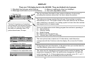
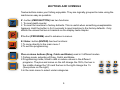
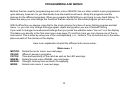
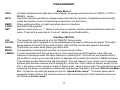
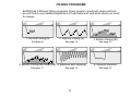
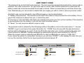
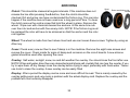
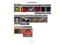
English manual for BJ5000
Instruction edition12
Programme version 4.0704
CONTENTS
Installation
Display
Buttons and symbols
Getting started
Spooling on the line
Some explanations
Programs and menus
Descriptions of programs
Normal fishing
Step jig fishing
Bottom fishing
Bottom fishing with step
Mackerel and squid
Spanish Mackerel
Display text
Anti-theft code
Error messages
Servicing, Clutch, Wheel, Case, Overlay, Screen
Technical information
Extra equipment
Guarantee
2
Page
3
4
5,6
7
7
8,9
10-12
13
14
15
16
17
18
19
20-27
31
28
32
29
33
30
Congratulations on an excellent choice of jigging machine.
Belitronic has produced electronic jigging machines since 1972, this was a worlds first. Since then we
have sold thousands of machines in 70 countries, mostly in Norway, Iceland and the Faeroe Islands.
APPROVAL
This machine BJ5000 is produced by Belitronic Sweden AB in Lunde Sweden in accordance with the
appropriate rules for CE approval and marking within EU and the EEC. The serial number is printed on
the outside label and also on the label under the gearbox.
The machine is only meant for fishing. It must be mounted in such a way that no danger occurs when
in use. It is very important that the spool, line and hooks cannot come in contact and injure the
operator of the machine.
The emergency stop button must be easily accessible. Check daily that the emergency stop is working.
The machine must be connected to either a 12 or 24v DC, the power source should be a Lead Acid
Battery. ( see the chapter about Installation )
The machine can only be used by those who have read and accepted the contents of this user manual.
INSTALLATION
Upon installation, take particular care with the mechanical, but most importantly the electrical
connections. If you are in doubt, contact a qualified electrician. Avoid damage to the power cable. An
important rule of thumb is that the longer the cable and the more extensions you have will give you
reduced functionality from the machine.
Check the EMERGENCY STOP BUTTON depressed before you connect the machine to the battery.
The power cable has to be connected directly to the battery. The two red wires are connected to the
batteries positive and the two blue wires to the negative. The procedure is the same for both 12 and 24
volts. The machine must always be connected directly to the battery or battery system. For safety
reasons and guarantee purposes, the machine must NOT be connected to any other power source.
3
DISPLAY
There are 130 display texts in the BJ5000. They are divided into 4 groups.
1. Standard text (shown while fishing)
2. Menus. Leading to other text displays.
3. Messages and alarms (Just information)
4. Text with adjustable values
1. Standard text
The first 10 symbols on the bottom
row show how much power the motor
is using. This can be used to adjust
the catch to a suitable value. The
picture here shows 12 amps.
The top row shows the depth in feet, meters or fathoms. A minus sign ”-”
preceding the numbers means that the line is above the surface.
The bottom row shows a symbol that tells you if the machine is working
automatically or not. This symbol rotates in the same direction as the wheel
and is stationary in a pause, if no rotating symbol is shown then the machine
has stopped and is in manual mode.
One or two letters show which fishing program the machine is operating in.
N = Normal fishing
S = Step jig fishing
B = Bottom fishing
BS = Bottom with step jig fishiung
M = Mackrel (also called squid fishing)
2. Example of a menu
3. Example of an alarm
The menu picture has a maximum of 6 alternatives, each alternative
corresponds with the 6 buttons under the display. Do not use the P-button
here.
Some pictures are just information. In the picture here you see the alarm for
Low Boat Battery, press enter to acknowledge.
4. Example of an adjustable value
The values can be changed by pressing the buttons under the display The
drag button changes the 100’s, the catch button changes the 10’s and the
brake changes the 1’s. All time adjustments are carried out on 10, 1, or 0.1
increments, when you are finished press the enter button.
4
BUTTONS AND SYMBOLS
Twelve buttons make your fishing enjoyable. They are logically grouped to make using the
machine as easy as possible.
Z - button (ZERO BUTTON) has two functions:
1. To reset depth counter
2. To reset the machine to factory defaults. This is useful when something unexplainable
happens. Hold the button in for 5 seconds to reset machine to the factory defaults . Only
affects the values that are in brackets on the display texts chapter.
P-button (PROGRAM) used to advance in menus.
E / Enter- button (ENTER) has two functions:
1.To come directly to the main menu 1
2.To exit the programming.
Plus or minus buttons (Drag, Catch and Brake) used in 3 different modes
1.Fishing mode, adjusting of Drag, Catch and Brake.
2.Programming mode, Used to add or reduce values in the different
programs. The plus and minus on the left change the 100’s, the two in
the middle change the 10’s and the two to the right change the 1’s
(See picture on the right)
3.In the main menu to select under categories.
5
100
10
1
BUTTONS AND SYMBOLS
A button (AUTOMATIC) means start fishing. If you hold in the button, the wheel will release
without brake. Every time it is pressed the program will start again.
↑ - button (UP) used to manually haul up the line. Press once quickly to haul up continuously
press again to stop the motor.
If you hold in the button then the machine will haul as long as you have the button pressed.
↓ - button (STOP/DOWN) stops everything, cancels all programs including manual hauling.
If you hold in the button the machine will pay out line with brake until released.
- symbol means DRAG. (Clutch symbol) This is the power at the wheel when the machine is
hauling or when the machine has stopped (Except when fishing using the Spanish Mackerel
program, then the depth drag applies.)
- symbol means BRAKE. Brakes the wheel when paying out line to avoid birds nests or backlash
- symbol means CATCH-sensitivity. When the power display exceeds the catch value over a short
time the machine will register catch.
6
GETTING STARTED
Turn on the machine by turning the EMERGENCY STOP push button lightly clockwise until it pops out. The
machine is now powered. Watch the display during start up as it provides information from the first few
seconds.
NB! If the display is dark; the machine is incorrectly connected to the battery. Switch polarity on the battery.
SPOOLING ONTHE LINE
1.Tie the line safely to the wheel. Set DRAG to minimum by pushing the
2. Push the
button under
symbol.
button rapidly. The motor will now run continuously, but without any power to the wheel.
3. Increase DRAG by pressing the
button under the
symbol until a smooth pull is applied to the Line.
4. When all the line is wound on, press STOP-button to stop the machine and then press the Z-button to reset
the electronic counter.
5. Don’t forget to set the correct line diameter and the diameter formed by the outermost diameter of line.
Measurement of the line will be done under the menus ”WHEEL” and ”LINE”. To help find the correct diameter
of the wheel after the line is wound on, there are some numbers on the outside of the wheel i.e., 160,180 and
200. These values are in millimeters. If the outside diameter of the line on the wheel falls in between these
numbers, the diameter can be estimated using the figures as a guide.
7
SOME EXPLANATIONS
Factory settings: Basic program of the machine. Average values are chosen at the factory to enable the
machine to work without any further programming. Therefore before you start fishing for the first time only
Depth and Jig length have to be set.
Catch and Alarm Beeper (Sounder): A built in beeper sounds when the catch is hooked. When the catch
is at the surface a slower beep will sound. Press STOP-button to silence the beeper. The beeper will also
sound warnings.
Light: Four built in LEDs signal catches and warnings in conjunction with the sounds of the beeper.
Speed limit: This brake function is activated if the sinker pulls out the line too rapidly. A maximum allowed
speed can be set together with the braking power when fishing. Factory settings are 600 rpm, 20% braking
power and activating time 1,0 sec.
Air Brake: The Same function as the speed brake above, but is only applicable over a set depth.
The function is designed to be used with the “Mackerel” fishing program when the hooks are in the boat.
Braking time and power are taken from the speed brake, but it has it’s own “speed” and “above depth”
values, that decide what depth the air brake will be activated for. Factory defaults are 600 Rpm at the wheel
and “above depth” =0. NB: Outside of these parameters speed brake is always used.
8
SOME EXPLANATIONS
Depth Brake: A function that reduces the speed of the line as it nears fishing depth. This reduces
unnecessary wear and tear of the motor and clutch. You can decide when and how the brake is activated.
The length of braking is given in time. The factory defaults are 400 Rpm at the wheel, 10% of maximum
brake strength happens 1,0 seconds before reaching set fishing depth.
Reverse wheel rotation: It is possible to change the hauling direction of the wheel. Take of the cabinet,
swap the cables from the motor on the circuit-board. Red cable connects to MOTOR (-) and the BLUE cable
to MOTOR(+).Now the motor will run the other way. To make the counter to count the other way, enter the
menu. Press E-button and choose ”WHEEL”, then choose “COUNTER”. Press the P-button and the display
will read “direction”. Press (+) button on the right until the display shows “Reverse”. Finish by pressing Ebutton.
Max depth: This function is found in the bottom fishing program, and used to correct line when the boat is
drifting in strong current or high winds. Two parameters are used here Max depth and Hauling up. Hauling
up is a percent of the Max depth i.e.. If the max depth is 100 and hauling p is at 25% then the machine will
haul the line up to 75 after the max depth is reached.
Soft stop: When hauling the machine reduces speed as it approaches the surface. Especially good when
the stop at pulley is used to save your catch and line.
Soft start: The motor always starts gradually with an adjustable acceleration to reduce power usage and
wear on the motor.
9
PROGRAMMING AND MENUS
Buttons that are used for programming are red in colour. BJ5000, like our other models is pre-programmed
upon delivery, however it is you that decide how the machine will work. Study the programs and the
pictures for the different programs. When you program the BJ5000 you are trying to copy hand fishing. To
make this easy you only change the functions that are relevant to the actual program you are using.
With the P button you always come first to the most common functions of every fishing program and last
menu. i.e. you can only change fishing program, depth and jig when you are in Normal Fishing.
If you wish to change more advanced settings then you press the ↵ button when “line out” is in the display.
This takes you directly to the first main menu (see page 11) and from here you can choose one of the six
sub menus. This is done by using one of the corresponding + or – buttons. The six buttons are in the same
place as each of the choices in the display.
Here is an explanation of what the different sub menus mean:
MOTOR:
PAUSE:
CATCH:
WHEEL:
BRAKE:
MORE:
Main menu 1
Enters the motor menu, see next page.
different pause in programs.
Time and sensitivity of the catch as well as the LED warnings.
Enters the sub menu WHEEL, see next page.
Strength, braking time and limits for applying.
Enters main menu 2, see next page.
10
PROGRAMMING
DISP:
INFO:
BEEP:
CODE:
RET:
JIG:
CATCH:
HAUL:
MANU:
L.MESS:
Main Menu 2
Contrast, brightness and light time of the display. Language and show time for DRAG - CATCH BRAKE - values.
information about boat battery voltage measured inside the machine. Temperature and humidity
inside the machine. Current measuring on electronic unit and motor.
When pushing buttons, at catch and when catch is at surface
Anti-theft locking system
Return to main menu no. 1. When a sub-menu is chosen, continue pressing P-button within the
menu. To get all the way back to ”Line out” display press the E-button.
Sub Menu MOTOR
The speed the machine will jig at in AUTOMATIC fishing mode
In the instance catch registers it can be advantageous to keep a relatively low speed. This catch
speed applies to the first 60 seconds at most, after that the normal haul speed is activated.
The Normal you want when hauling up after catch.
The speed the machine hauls up when you press the up button..
It is not uncommon that the line from two or more machines can drift together. Very often one
machine is hauling up while the other machine is standing still. The line from the machine that is
still is often in a big curve under the water. To alleviate this problem the function L.MESS activates.
The machine senses that the line has lost weight. This will happen if your sinker or line is tangled
together with another machine that is hauling up. When the motor hauls up without weight on the
line, it will reduce motor current a couple of Amps under Value for line mess. The machines processor
measures the power consumption continuously and decides that after a set time ”Detect Line Mess
For” it ill haul the line with the speed you set for “Speed at line mess”. To reduce false alarms
caused by bottom fishing, the machine does not start monitoring until it has hauled the value set
for "Distance for line mess”.
11
PROGRAMMING
Sub Menu WHEEL
Value you set for the amount of line you have on the wheel, not in meters, but the height of
the nylon compared to the three number on the outside of the wheel.
LINE:
The diameter of the line in mm. Very important for correct measuring of the depth.
COUNTER: Parameters for the counter display, Feet, Fathoms or Meters. Direction of travel for the line on
the wheel (see Reverse wheel rotation). Test picture for counter .
STOP-P:
Go directly to sub menu STOP-P (see under).
RP:
This controls the magnetic field of the clutch. This only applies to machines with the older
version clutch prior to serial no. 684900 and requires a RP-card mounted.
RET:
Return to main menu no. 1. When a sub-menu is chosen, continue pressing P-button within
the menu. To get all the way back to ”Line out” display press the E-button.
DIM:
Sub Menu STOP-P
Setting of where you want the wheel to stop when the counter reaches zero and displays ”-000”.
Change to OFF if you wish to stop at pulley.
SEA:
Maximum running time of the motor if the wheel stops. Cannot be deactivated
PULLEY:
Maximum running time of the motor if you want to stop at pulley, and not use ZERO (see
above). More features such as running time, Above depth, Auto restart and Auto Zero can be
chosen.
SOFT STOP:Settings for the soft stop when the line approaches the zero point (000 in the counter).
RET:
Return to the previous menu and to sub menu WHEEL . When a sub-menu is chosen, continue
pressing P-button within the menu. To get all the way back to ”Line out” display press the
E-button.
ZERO:
12
FISHING PROGRAMS
BJ5000 has 6 different fishing programs. Every program is built with steps and here
you will find a more detailed explanation of how these work and what values you need
to change.
1. Normal Fishing(N)
2. Step Jig Fishing (S)
3. Bottom Fishing (B)
See page14.
See page 15.
See page 16.
4. Bottom Fishing with Step (BS) 5. Mackerel and Squid(M)
See page 17.
See page 18.
13
6. Spanish Mackerel
See page 19.
NORMAL FISHING(N)
Diagram 1
Normal Fishing (N)
The simplest fishing program. See diagram 1.
Comprises of three parts
1.Depth is the depth you want to fish at.
2.Jig is the length that you want the machine to haul up
before it releases and goes down.(Step length)
Depth
Jig
3.Depth pause is the amount of time you want the
machine to wait before hauling the step length. Depth
pause can be changed with ”PAUSE” in main menu 1
Depth pause
Time
Programming of ”Normal Fishing”:
1. Push the P -button to go into the programming mode, check that display shows ”Fish program (N)” in
upper row and ”Normal fishing” in the lower. If not, change by using the +/- buttons.
2. Push the P -button once more and adjust the fishing depth by pressing the +/- buttons. All six buttons
can be used. The left ones for 100’s-settings, the middle for 10’s-settings and the right for 1’s-settings.
3. Push the P -button again select ”Step length”. In the following diagrams you can see a picture, as it
would appear in your echo sounder, of the movement of the sinker during fishing.
14
STEP JIG FISHING (S)
Diagram 2
Step jig fishing (S)
Normal fishing combined with step jig. (See diagram 2).
Step jig means that every jig length is divided into step lengths
with step pauses between. The two extra functions are:
1.Step Length: The length that you want to haul within a jig
length.
2.Step pause: The pause between two step lengths.
example: If you want to fish at 50meters, with a jig length of 7
meters, you can set the step length to 2 meters and step pause
To 3 seconds. The machine will then release 50 meters, stop
for the depth pause then haul 2 meters (step length), stop for 3
Seconds (step pause), haul 2 meters, stop 3 seconds and so
On until 7 meters (jig length) is reached. The machine will then
release the line to 50 meters and start again.
Depth
Step length
Jig
Depth pause
Step pause
Programming Step Jig Fishing
1. Push the P -button to enter the programming mode. Select the program by using the right +/--buttons.
Read ”Fish method (S)” in the upper row of the display and ”Step Jig fishing” in the lower row of the
display.
2. Push the P -button again and select ”Depth”
3. Select ”Jig length”.
4. Decide the ”Step length”.
5. Select ”Step pause”.
15
Time
BOTTOM FISHING (B)
Means fishing close to bottom. See diagram 3.
The machine will hold the sinker close to the bottom even if the
depth changes over time. Fishing depth can be chosen.
Three new functions are added to this program:
1. Detect time is the time the machine needs to register
the sea bed. From when the wheel stops rotating to when the
Machine starts hauling is regulated by the bottom pause
Then the machine will haul the bottom distance + jig length.
2. Bottom dist. is the depth at which the fishing shall
be undertaken over the sea bed.
3. No of jigs. This is the number of jigs that the machine
will make before it will try to find the sea bed again.
Bottom Fishing (B)
Diagram 3
No. Jigs
Depth pause
Jig
Bottom dist.
Bottom pause
Time
Programming Bottom fishing:
1.Press the P-button to enter the fishing program menu. Choose bottom fishing in the lower line of the
display.
2.Press the P-button again. Choose the DEPTH. Depth can be used to simulate a sea bed, but if you want
to fish on the sea bed you have to set the depth deeper than the sea bed actually is.
3.Press the P-button again and choose ”Jig length".
4.Press the P-button and choose ”Bottom pause" which is the time from when the sinker hits the sea bed to
when the machine starts hauling. When the sinker hits the bottom or goes slowly, the time of the bottom
pause is designed to calculate one revolution of the wheel. If no revolution is detected then the machine
assumes that you arte on the sea bed.
5.Press the P-button and choose your ”Bottom distance”.
6.Press the P-button and choose ”No. of jigs” before finding the sea bed again
7.Press the P-button and choose ”Max depth". For correcting your line in strong currents or drifting
8.Press the P-button and choose ”Hauling up”. How far you want the line to haul up when reaching max
depth
16
BOTTOM FISHING WITH STEP (BS)
Bottom fish with step(BS)
Bottom fishing and step (BS)
A combination of bottom fishing and step jig fishing program.
See bottom fishing (page 16) and Step jig fishing (page 15)
for more details.
Diagram 3
Step pause and Step length
Depth pause
No. Of jigs
Jig length
New bottom detection
Bottom pause
Bottom distance
Time
Programming of ”Bottom and Step”:
1.Press the P-button to enter the fishing program menu. Choose “Bottom and Step” in the lower line of the
display.
2.Press the P-button again and choose ”Depth” with the plus or minus buttons.
3.Press the P-button again and choose "Jig length".
4.Press the P-button and choose ”Bottom pause" which is the time from when the sinker hits the sea bed to
when the machine starts hauling. When the sinker hits the bottom or goes slowly, the time of the bottom
pause is designed to calculate one revolution of the wheel. If no revolution is detected then the machine
assumes that you arte on the sea bed.
5.Press the P-button and choose your ”Bottom distance”.
6.Press the P-button and choose ”No. of jigs” before finding the sea bed again
7.Press the P-button and choose "Step length”.
8.Press the P-button and choose ”Step pause".
9.Press the P-button and choose ”Max depth". For correcting your line in strong currents or drifting
10.Press the P-button and choose ”Hauling up”. How far you want the line to haul up when reaching max
depth
17
MACKEREL AND SQUID FISHING (M)
Diagram 4
Mackerel / Squid fishing (M)
This is popular for trolling Mackerel and Squid.
”Jig length” cannot be adjusted as the machine hauls up
To the surface each time. Two new functions are used
1.Depth reduction: How much the machine will reduce the
Fishing depth every time it hauls up.
1.Minimum depth: is the depth the machine will end up at
after fishing for a while
Minimum Depth
Depth
Depth reduction
Example: if you are fishing at 50 meters, with a depth
Reduction of 5 meters and a minimum depth of 30 meters
Time
This will happen: When the Auto button is pressed the
Machine will release 50 meters of line, brake and haul up to
Zero, then release to 45 meters haul up to zero and then release to 40 meters until you come to the
minimum
Depth (30 meters). It will continue to fish at the minimum depth until you press stop. When you press auto
Again it will go back to 50 meters and do the procedure again
Programming of ”Mackerel fishing”:
1.Press the P-button and choose ”Mackerel Fishing”
2.Press the P-button and choose ”Depth”.
3.Press the P-button and choose ”Depth reduction”.
4.Press the P-button and choose "Minimum depth”.
18
SPANISH MACKEREL FISHING
Diagram 5
Spanish mackerel fishing
Spanish mackerel is the same as normal fishing
without a jig length. Catch occurs when the fish drags
line from the wheel. Two new functions are used.
1.Wheel Laps (revolutions) : The amount of
revolutions needed before the machine registers a
catch.
2.Depth Drag: The amount of brake the machine
applies to hold the wheel whilst trolling, after the
depth pause is over. This value should be set lower
than the value for normal drag so that the fish can
pull line from the wheel.
Depth
No. Of wheel laps
Catch
Programming the Spanish Mackerel function.
1. Press the P -button to go into the programming mode, check that display shows ”Fish program
(N)” in upper row and ”Normal fishing” in the lower. If not, change by using the +/- buttons.
2. Press the P-button and choose ”Depth
3. Press the P-button and adjust ”Jig” to 0
4. Press the P-button and choose ”Spanish Mackerel” and set wheel laps to at least 1. If you don’t
have a value entered then you cannot use ”Spanish Mackerel”
5. Press the P-button and adjust ”Spanish Mackerel” Depth drag to required strength so that the
wheel is stationary awaiting catch. If you choose ”Out” on depth drag then the drag will be the
same as the main drag of the machine.
19
Time
Min
Max Fact. Units
XXX
< XX
0
999
Fish program
XXXXXXXXXXXXXXX
0
4
Depth
XXX
0
Jig
XXX
Display Picture
LINE OUT:
DISPLAY TEXT
Notes
1
Normal display picture.
0
1
Choice of fishing program.
999
20
1
Choice of fishing depth and maximum depth for Bottom fishing.
0
999
10
1
Choose Jig length
STEP JIG PROG
Length
XX
1
100
2
1
Choose Step length
STEP JIG PROG
Pause
XX.X
0,5
10,0
2,0
0,1
Choose Step pause
BOTTOM PROG
Detect Time XX.X
0,5
999,9 2,0
0,1
Bottom pause is the time the machine needs to register sea bed
BOTTOM PROG
Bottom dist.
XX
0
20
2
1
Distance from the sea bed when bottom fishing
BOTTOM PROG
No. Jigs
XX
1
25
10
1
No. Of jigs between sea bed registering
BOTTOM PROG
Max depth
XXX
1
999
999
1
BOTTOM PROG
Hauling up
XX%
1
100
50
1
The maximum depth the machine will accept before realising that
there is slack in the line and before haling up is activated
How much of the depth the machine will haul up when max depth
is reached
20
DISPLAY TEXT
Display picture
Min
Max Fact. Units
MACKEREL PROG
Depth pause XX.X
1
10
1
1
Pause before the machine hauls in mackerel program.
MACKEREL PROG
Depth reduc
1
10
2
1
Reduction of line every time the line goes out.
0
999
5
1
Fishing depth after depth reduction is carried out.
UT
10,0 1,0
0,1
Acceleration time of the motor when jig starts.
XX
MACKEREL PROG
Min depth
XXX
Soft start to jig
speed
XX.X
Notes
Speed at
Jig
XXX
1
160
120
1
Haul speed when jigging
Speed at
Catch
XXX
1
160
50
1
Speed directly after catch is registered
Catch speed
time
XX X
UT
60,0
UT
0,1
The amount of time the catch speed should last
UT
10,0
2,0
0,1
1
160
120
1
Acceleration time of the motor from ”Speed at catch” to
”Speed at haul”
Haul speed when coming up with catch
Soft start to
Manual speed XX.X
UT
10,0
1,0
0,1
Acceleration time for manual hauling
Speed at
Manual
1
160
120
1
The speed of the motor when hauling manually
Soft start to
haul speed
XX.X
Speed at
Haul
XXX
XXX
21
DISPLAY TEXT
Display picture
Min
Max Fact. Units
Notes
SPANISH MACKEREL
Wheel laps
XXX
OFF
30
OFF
1
SPANISH MACKEREL
Depth drag
XXX%
0
20
4
1
Number of wheel rotations backwards before catch is
registered
Power of the brake when holding position
Speed at
Line mess
OFF
160
OFF
1
Speed of the motor when tangled in another line
Value for Line
mess (Amp).
XX
0
20
4
1
Reduction of power before line mess is activated
Detect time for
Sline mess XX.Xs
1
50
10
0,1
Distance for
line mess
XX.Xs
0
999
5
1
PAUSES
Auto
XX.X
0,5
10,0
0,5
0,1
The amount of time the value for line mess is reduced
before line mess function is activated
The length that must be hauled, calculated from the start of
a jig length, before line mess is activated.
Pause before the machine starts fishing when pressing AUTO
PAUSES
Depth pause
XX.X
0,5
25,0
2,0
0,1
Pause before the machine starts hauling
CATCH
Time up
XX.X
0,1
10,0
1,0
0,1
Time needed to register catch when hauling
NAPP
Time down
XX.X
1,0
25,0
OFF
0,1
OFF
Time needed to register catch when the line stops or goes
slowly upon descent ( not bottom fishing)
Catch can be registered if the speed at the wheel so great
that the speed brake activates.
Brightness
XXX
CATCH AT
Speed brake
XXX
OFF
ON
CATCH BLINK
Brightnss
XXX%
OFF
100% 100% 1%
XXX
OFF
99,9
CATCH
Restart
OFF
0,1
After catch the machine can restart automatically at zero
without Having to press the auto button
22
DISPLAY TEXT
Display picture
WHEEL
Width
XXX
LINE
Line dia.
X.X
LINE
Outer dia.
XXX
Min
Max Fact. Units
Notes
1
999
80
1
Wheel width in millimetre
1,0
5,0
1,4
0,1
Diameter of line in millimetre
130
400
170
1
Amount of line on wheel. Se page 7.
Meter - Feet – Fathoms. Choice of measuring units.
Factory setting is fathoms.
LINE COUNTER
Unit
XXXXX
If you want the wheel to turn the other way except upon
delivery you have to change the direction of the line
counter=reverse. Factory setting is Normal. (NOTE! Factory
resetting will not change this back)
Check pulses from the line counter
LINE COUNTER
Direction
XXXXX
Wheel count
0000
A B
1 1
Stop at 0 ?
XXX
STOP AT
Tid
XX.X
STOP AT PULLEY
Time
XX.X
STOP AT PULLEY
Above depth
XXX
STOP AT PULLEY
Restart
XX.X
OFF
ON
ON
Machine stops when the counter shows zero
1,0
99,9
30,0
0,1
Maximum hauling time of the motor with line mess
OFF
99,0
OFF
0,1
1
50
20
1
The time that the wheel must be motionless before the
machine thinks the line is at pulley.
Sop at pulley is only activated over this depth.
0,1
60,0
OFF
0,1
Delayed start after stop at block is activated.
23
DISPLAY TEXT
Display picture Min
STOP AT PILLEY
Auto zero
XXX
Max Fact. Units
Notes
OFF
ON
OFF
-
OFF
99
8
1
OFF
99
OFF
1
RP-card
T1 @ 12V
XXX
0
999
100
1
This zero’s the counter every time the A-button is pressed
When the machine has stopped because the hooks are pulled
into the pulley.
When soft stop at zero is used a reduction of speed is
calculated from a defined number of wheel revolutions from the
zero point
When soft stop at zero is used a reduction of speed calculated
from a defined distance from the zero point
Pause between de-magnetising pulses 12 volt not in seconds
RP-card
T2 @ 12V
XXX
0
20
5
1
Length of de-magnetising pulses 12 volt.
RP-card
Puls @ 12V
XXX
0
5
2
1
Number of de-magnetising pulses 12 volt.
RP-card
T1 @ 24V
XXX
0
999
200
1
Pause between de-magnetising pulses 24volt not in seconds
RP-card
T2 @ 24V
XXX
0
20
5
1
Length of de-magnetising pulses 12 volt..
RP-card
Puls @ 24V
XXX
0
5
2
1
Number of de-magnetising pulses 12 volt.
OFF
0
20
1
How much braking power will be used at speed limit
0,1
5,0
1,0
0,1
How much time will be used on speed brake
50
900
400
1
Which speed the speed brake will activate at
Soft stop at 0
In mode auto
XX
Soft stop at 0
In mode menu
XX
SPEED
Brake
XX%
SPEED
Brake
X.X
LIMIT
power
LIMIT
time
SPEED LIMIT
Max speed
XXX
24
DISPLAY TEXT
Display picture
Min
Max Fact. Units
Notes
DEPTH BRAKE
Force
XX%
OFF
100% 10%
1
How much power to use at depth brake.
DEPTH BRAKE
Time
X.X
0,1
5,0
1,0
0,1
How long the depth brake will activate for
DEPTH BRAKE
Max speed
XXX
50
900
400
1
Which speed the depth brake will activate at.
AIR BRAKE
Speed
XXX
50
OFF
600
1
Which speed the air brake will activate.
AIR BRAKE
Above depth
XXX
0
999
0
1
Above which depth will the air brake activate
DISPLAY
Contrast
XX%
0
100
70
1
Adjusting of contrast to get the best picture
DISPLAY
Brightness
XX%
0
100
80
1
Brightness of the display
DISPLAY
Ligh time
XX.X
OFF
ON
ON
0,1
How long the display will be illuminated after last touch
DISPLAY
Language
Choice of language
ENGLISH
DRAG CATCH BRAKE
Showtime XXX
INFORMATION
Voltage(V) XX.X
INFORMASTION
Temp (°C)
XX.X
0,5
20
4,0
Info. only
Info. only
0,1
The time that DRAG–CATCH-BRAKE will be displayed after
the last touch.
Shows the voltage at the machine
Shows the temperature in the machine. Normally not over 25°
above the outside temperature
25
DISPLAY TEXT
Display picture
INFORMATON
Motor(Amp)
Min
Max Fact. Units
Notes
Info. only
Shows how much power (amp) the motor is using
Choose if you want beep when pressing buttons
XX
Beep at pushbutt.
ON
OFF
ON
ON
Number of beep at
catch
XX
OFF
99
30
1
Choose how many beeps you want at catch.
Catch beep at 0
Pause
XX.X
OFF
60
5,0
0,1
Choose how long pause between beeps when the catch is
hauled up to the surface.
Choose between: ”Never”—”Battery disconnected” or
”Turning on”
CODE AT
XXXX
CODE ?
XXXXXh
XXXXXX
----------<DRAG
----------<AMP
----------<CATCH
----------<AMP
----------<BRAKE
----------<AMP
Catch depth XXX
000000 - 999999
Own choice of code from 000000 to 999999
0
100
18
2
Bar that shows drag power in steps; 2% of 100% in top row
and Motor power in steps; 1 amp in bottom row.
0
50
7
1
Bar that shows catch in steps; 1 amp of motor power in top
row and Motor power in steps; 1 amp in bottom row
0
100
30
2
Bar that shows brake power in steps; 2% of 100% in top row
and Motor power in steps; 1 amp in bottom row
Shows the depth where catch occurred
Info. only
26
DISPLAY TEXT
Display picture Min
Max Fact. Units
Notes
belitronic´s
BJ500X
Info. only
Version X.X
System XXV
Info. only
The first picture when turning on the machine. BJ5001=Old model
Machine. BJ5002=New type of machine.
Second picture . Shows the software version in the top row
and which battery system(12 or 24V) you are connected to.
Serie No:
XXXXXX
Info. Only
Third picture tells you the serial number of the mother board
Factory restet
Values
Info. only
Factory reset happens after the Z-button is held for over 5 secs.
LOW BOAT BATTERY
Press button ↵
Info. only
ALARM. Shows when the battery power is too low measured at.
The machine. Acknowledge by pressing E-button
MEMORY MESS
Press button
↵
MOTOR PAUSE CATCH
WHEEL BRAKE MORE
DISP
CODE
INFO
BEEP
RET
JIG CATCH HAUL.
MANU L.MESS RET
DIM LINE COUNTER
STOP-P. RP
RET
ZERO SEA PULLEY
SOFT S.
RET
Info. only
ALARM. Software error
Main menu 1. Shown when E-button is pressed whilst showing line
out in display
Main menu 2 shown by pressing more in main menu 1
Sub menu MOTOR . Choose ”MOTOR” in main menu 1.
Sub menu WHEEL. Choose ”WHEEL” in main menu 1.
Sub menu STOP-P. Choose ”STOP-P” in sub menu WHEEL.
27
ERROR MESSAGES
LOW BOAT BATTERY
The voltage at the machine is ad. In a 12-volt system the alarm sound when the voltage drops under 10
volts. In a 24-volts system no alarm will sound unless you go under 10 volts. If alarm sounds check the
cable, extensions, batteries and the charging.
MEMORY ERROR
The built in memory will remember the personal settings as well as other data, and can have errors
Press the E-button, but if this does not work hold in the Z-button until the machine re-loads the factory
settings. Most of the problems that occur while using the machine can be resolved by holding the Zbutton. There are many values that can conflict other setting and resetting the machine can resolve
these issues.
28
TECHNICAL INFORMATION
Machines weight:
12 Kg
Power use with full resistance
12Volt
30 Amps max
Power use with full resistance
24Volt
15 Amps max
Average power use while
fishing:
3-4 Amps
Voltage range:
12-30 Volt DC
Cable dimension:
7 Meter 4x2,5mm²
Line capacity:
~500 Meter 1,4mm line
Maximum fihing depth
999 meter, fathoms, feet
Motor speed:
1-170 rpm
Accuracy measurig depth
Almost 100%
Guarantee:
2 Years
Panel
12 lighted buttons
4 LED Catch indicators
2*16 Text display, with
background lighting
Acoustic signal at catch
29
GUARANTEE
Guarantee of this machine is one year (two in Nordic countries) from day of purchase,
covering production- and material faults. Invoice or receipt is accepted as warranty notes
If a problem occurs with your machine within the guarantee period the machine will be repaired
free of charge. After guarantee period the service or repair of the electronics will be at fixed price.
Guarantee covers both spare parts and labour. The guarantee covers production and material
faults, and does not cover accidental damage, wrong mechanical or electrical service .Guarantee
does not cover damage or bad functionality caused by wrong use or rough handling,
unreasonable use, or other similar causes.
Guarantee does not cover loss of catch
Guarantee does not cover freight charges.
If your machine does not function properly, under certain circumstances a substitute machines
from local dealer may be available during repair period.
The manufacturer and dealer are not responsible or secondary damage, loss or expenses that
are associated with the use of the jigging machine.
30
ANTI THEFT CODE
The machine has an Anti-theft code and lock. The lock cannot be deactivated before the correct code is
entered. The code is personal. You get three tries to unlock, after that the machine is locked and the
battery cable has to be disconnected for at least a minute. When reconnected you will have three new
tries. Alternatively you can contact a dealer that can supply you with a code to remove previous codes.
Anti theft code can be activated in two different ways or can be deactivated
1: ”Battery disconnected”. The machine locks itself if the cable is disconnected from the battery. This is
good if the machine is stolen from you, it cannot be used.
2: ”Turning on” The anti theft code has to be entered every time you turn on the machine. If the machine
is disconnected from the battery, it will still lock itself as written above.
3: ”Never” You will never be asked to input a code
The personal code is entered by the following method. Press E-to come to the main menu 1”, choose
”MORE” to go to next menu then press the button for ”CODE” then choose with the plus and minus
buttons which alternative you want. Press the P-button and enter your code by pressing the plus and
minus buttons for BRAKE, change sideways by pressing the plus an minus buttons for CATCH
When the correct code is entered press P-button to save and E-button to return to “LINE OUT”.
If you chose the option for code when turning on you will see “CODE?” in the display the next time you
turn on the machine. Enter the six figure personal code and press P
Number up
Changes pos. right
Changes pos. left
Number down
31
SERVICING
Spool
Clutch: This should be cleaned at regular intervals. If the machine does not
release the line after pressing the A-button, then the clutch should be
checked. Dirt and grime can have contaminated the friction ring. This can also
happen if the machine has not been used over a long period of time. To clean
the clutch remove the centre screw that hold the wheel in place. Remove the
wheel. Wipe over with chemical cleaner like acetone. At the same time rub
over the rotor and anchor with fine emery cloth. NOTE! If the friction ring must
be replaced the rotor will have to be skimmed so that the anchor and the rotor
rub together.
Rotor med friction ring
Anchor
Wheel: The wheel is made from two halves. Heat and use can loosen these screws. Tighten by using an
Allen key.
Cover: Check every now an then to see if damp is in the machine. Remove the eight case screws and
remove the cover. Check inside for signs of damp and corrosion on the circuit boards. A new silicone
gasket should be used after opening the cover.
Overlay: Salt water, sunlight, snow, ice and dirt weather the overlay. You should rinse the front after use.
NOTE! When salt water dries there are deposited small sharp salt crystals that can tear the overlay if you
try to wipe them off dry. Always rinse the overlay before trying to wipe, preferably with fresh water . Never
use tools to clean the overlay. A new overlay can be easily fitted
Display: After a period the display can be more and more difficult to read. This is mainly caused by the
overlay getting worn and very rarely a problem with the actual display card. Replace the overlay and the
problem will most certainly disappear
32
ACCESSORIES
Mackerel
Wheel
Nut protectors
Pole
Pulleys
Red
Stand Pole
Lines
In dimension
40 og 50 mm
Monofil og
Dyneema
Protective covers
Hooks
Extra cable 4*4mm²
In 7m lengths or
your own lenght
33
Black
Sinkers
Blue
Thank you for purchasing the BJ5000 and good luck!
Belitronic Sweden AB
Rättarevägen 5, 872 63 Lunde, Sweden
Telefon +46 612-320 00
Fax +46 612-320 01
www.belitronic.se
[email protected]