1
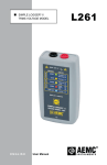
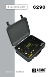
AX501
AX502
AX503
DC POWER SUPPLY
AX 501
VOLTAGE
CURRENT
8.8.8.
8.8.8.
V
A
LIMIT
30V
2.5A
0
0
FINE
COARSE
POWER
ON
OFF
100V
CAT I
IEC 61010-1
AX 503
8.8.8. 8.8.8.
TRACKING
ON
MASTER
A
SLAVE
V
LIMIT
8.8.8. 8.8.8.
V
30V
A
LIMIT 5A
V
LIMIT
2.5A
30V
2.5A
3V
5V
2.7V
0
5.5V
0
0
FINE
0
FINE
COARSE
POWER
ON
OFF
100V
CAT I
IEC 61010-1
ENGLISH
User Manual
100V
CAT I
100V
CAT I
COARSE
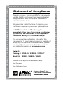
Statement of Compliance
Chauvin Arnoux®, Inc. d.b.a. AEMC® Instruments
certifies that this instrument has been calibrated
using standards and instruments traceable to
international standards.
We guarantee that at the time of shipping your
instrument has met its published specifications.
An NIST traceable certificate may be
requested at the time of purchase, or obtained
by returning the instrument to our repair and
calibration facility, for a nominal charge.
The recommended calibration interval for this
instrument is 12 months and begins on the date of
receipt by the customer. For recalibration, please
use our calibration services. Refer to our repair
and calibration section at www.aemc.com.
Serial #: _________________________________
Catalog #: 2130.05 / 2130.06 / 2130.07
Model #: AX501 / AX502 / AX503
Please fill in the appropriate date as indicated:
Date Received: __________________________________
Date Calibration Due: ________________________
Chauvin Arnoux®, Inc.
d.b.a AEMC® Instruments
www.aemc.com
Table of Contents
1.INTRODUCTION................................................................................ 3
1.1
1.2
1.3
1.4
International Electrical Symbols.................................................3
Definition of Measurement Categories......................................4
Receiving Your Shipment...........................................................4
Ordering Information..................................................................4
1.4.1Accessories...................................................................4
2. PRODUCT FEATURES....................................................................... 5
2.1 Description.................................................................................5
2.2 Control Features........................................................................6
2.2.1 Model AX501.................................................................6
2.2.2 Model AX502.................................................................7
2.2.3 Model AX503.................................................................8
2.3 Control Descriptions..................................................................9
2.3.1 Power On/Off Button......................................................9
2.3.2 Voltage and Current Adjustments..................................9
2.3.3 Current “LIMIT” LED......................................................9
2.3.4 “TRACKING” Switch (Models AX502 and AX503)..........10
2.3.5 Setting “TRACKING”....................................................10
2.3.6 Digital “LED” displays.................................................. 11
2.3.7 Output Terminals.......................................................... 11
2.3.8 Ground Terminal.......................................................... 11
2.4 Power Supply........................................................................... 11
3.SPECIFICATIONS........................................................................... 12
3.1 Specification Chart...................................................................12
3.2 General Specifications.............................................................13
3.3 Safety Specifications...............................................................14
4.OPERATION................................................................................... 15
4.1 Before Using the Instrument....................................................15
4.2 Operating Instructions..............................................................15
4.2.1 Using Independent Outputs.........................................16
4.2.2 Use of 2 Outputs in Parallel (AX502 and AX503)........16
4.2.3 Use of 2 Outputs in Series (AX502 and AX503)..........17
4.2.4 Use of 2.7V to 5.5V (5A) Power Supply (AX503 Only)....18
5.MAINTENANCE.............................................................................. 19
5.1
5.2
5.3
5.4
Warning...................................................................................19
Fuse Replacement...................................................................19
Cleaning...................................................................................19
Storage....................................................................................19
Repair and Calibration............................................................................20
Technical and Sales Assistance.............................................................20
Limited Warranty....................................................................................21
Warranty Repairs....................................................................................21
CHAPTER 1
INTRODUCTION
WARNING
These safety warnings are provided to ensure the safety of personnel
and proper operation of the instrument.
•Read this user manual completely and follow all the safety information
before attempting to use or service this instrument.
•Use caution on any circuit: Potentially high voltages and currents
may be present and may pose a shock hazard.
•Only use leads with the proper rating. Always inspect the instrument
and lead prior to use. Replace any defective parts immediately.
•Safety is the responsibility of the operator!
•Any defective lead insulation, inside or outside of the instrument, or
disconnection of the protective earth/ground terminal may make the
instrument dangerous.
•The plug should only be inserted into a socket equipped with a
grounding contact. The safety connection must not be broken by
use of an extension lead without protective insulation.
•Before connecting the power supply, make sure the distribution network is 115VAC ±10%.
1.1
International Electrical Symbols
This symbol signifies that the instrument is protected by double or
reinforced insulation. Use only specified replacement parts when
servicing the instrument.
This symbol on the instrument indicates a WARNING and that
the operator must refer to the user manual for instructions before
operating the instrument. In this manual, the symbol preceding
instructions indicates that if the instructions are not followed,
bodily injury, installation/sample and product damage may result.
Risk of electric shock. The voltage at the parts marked with this
symbol may be dangerous.
Earth/Ground
DC Power Supply Models AX501, AX502 and AX503
3
1.2
Definition of Measurement Categories
CAT I: For measurements on circuits not directly connected to the AC
supply wall outlet such as protected secondaries, signal level,
and limited energy circuits.
CAT II: For measurements performed on circuits directly connected to
the electrical distribution system. Examples are measurements
on household appliances or portable tools.
CAT III: For measurements performed in the building installation at
the distribution level such as on hardwired equipment in fixed
installation and circuit breakers.
CAT IV: For measurements performed at the primary electrical supply
(<1000V) such as on primary overcurrent protection devices,
ripple control units, or meters.
1.3
Receiving Your Shipment
Upon receiving your shipment, make sure that the contents are consistent
with the packing list. Notify your distributor of any missing items. If the equipment appears to be damaged, file a claim immediately with the carrier and
notify your distributor at once, giving a detailed description of any damage.
Save the damaged packing container to substantiate your claim.
1.4
Ordering Information
DC Power Supply Model AX501........................................... Cat. #2130.05
(Single output, 0 to 2.5A; 0 to 30VDC)
DC Power Supply Model AX502........................................... Cat. #2130.06
(Dual output, 0 to 2.5A; 0 to 30VDC)
DC Power Supply Model AX503........................................... Cat. #2130.07
(Triple output, two 0 to 2.5A; 0 to 30VDC; 5A; 2.7 to 5.5VDC)
1.4.1Accessories
Lead Set (2 color-coded leads, 1 ground lead,
2 alligator clips and 2 grip probes)....................................... Cat. #2117.78
Set of 5 Fuses 10A/250V, 5x20mm Slow Blow.................... Cat. #2118.83
Order Accessories and Replacement Parts Directly Online
Check our Storefront at www.aemc.com/store for availability
4
DC Power Supply Models AX501, AX502 and AX503
CHAPTER 2
PRODUCT FEATURES
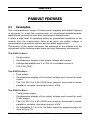
2.1Description
This comprehensive range of linear power supplies with digital displays
is designed to meet the requirements of educational establishments,
laboratories, production tests and maintenance departments.
It offers a high level of operating safety by guaranteed insulation of the
outputs from the mains when used at an extra low safety voltage, a
comprehensive protection system and excellent ergonomics.
The quality of the signal delivered, the precision of the display and the
robustness of the housing make them top-level laboratory instruments.
The AX501 offers:
• Single output
• Simultaneous display of the output voltage and current
• Voltage adjustable from 0 to 30V for a variable current of
0 to 2.5A (75W)
The AX502 offers:
• Dual output
• Simultaneous display of the output voltage and current for each
output
• Two 0 to 30V, 0 to 2.5A (150W max) outputs; connected in series,
parallel or coupled, (tracking function) ±30V
The AX503 offers:
• Triple power supply
• Simultaneous display of the output voltage and current for each
0-30V output
• Two 0 to 30V, 0 to 2.5A (150W max) outputs; connected in series,
parallel or coupled, (tracking function) ±30V
• An adjustable 2.7 to 5.5V, 5A fixed output for supplying logic circuits at 3V or 5V
DC Power Supply Models AX501, AX502 and AX503
5
2.2
Control Features
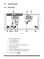
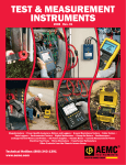
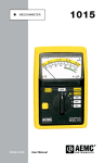
2.2.1 Model AX501
2
1
4
5
6
7
9
8
3
10
Figure 1
1. Voltage display (green)
2. Current display (red)
3. Current limit LED
4. Power On/Off button
5. Fine voltage adjustment potentiometer
6. Output terminal (+)
7. Output terminal (-)
8. Coarse voltage adjustment potentiometer
9. Current limit adjustment potentiometer
10. Ground terminal (
6
)
DC Power Supply Models AX501, AX502 and AX503
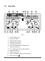
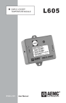
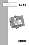
2.2.2 Model AX502
2
1
6
7
8
9
3
4
5
1
6
10 11
2
9
3
10 8 12
11
Figure 2
1. Current display (red)
2. Current limit LED
3. Voltage display (green)
4. Tracking function LED
5. Tracking On/Off switch
6. Current limit adjustment potentiometer
7. Power On/Off button
8. Fine voltage adjustment potentiometer
9. Output terminals (+)
10. Output terminals (-)
11. Coarse voltage adjustment potentiometer
12. Ground terminal (
)
DC Power Supply Models AX501, AX502 and AX503
7
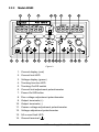
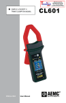
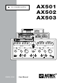
2.2.3 Model AX503
2
1
6
7
8
9
3
4
5
9 12 10 13 6
10 11
1
2
9
3
10 8 14
11
Figure 3
1. Current display (red)
2. Current limit LED
3. Voltage display (green)
4. Tracking function LED
5. Tracking On/Off switch
6. Current limit adjustment potentiometer
7. Power On/Off button
8. Fine voltage adjustment potentiometer
9. Output terminals (+)
10. Output terminals (-)
11. Coarse voltage adjustment potentiometer
12. Voltage adjustment potentiometer
13. 5A current limit LED
14. Ground terminal (
8
)
DC Power Supply Models AX501, AX502 and AX503
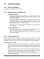
2.3
Control Descriptions
2.3.1 Power On/Off Button
Used to turn the power ON and OFF.
2.3.2 Voltage and Current Adjustments
• Voltage Adjustment:
- Sets the regulated voltage output by turning the large knob
(COARSE adjustment) to the right (increases output) or left
(decreases output).
- Sets the regulated voltage output by turning the small knob
(FINE adjustment) to the right (increases output) or left
(decreases output). The FINE adjustment range represents
approximately 10% of the main range.
- The value of the voltage output is displayed in real time on the
green display.
• Current Adjustment:
- Adjust the value of the current limit by turning the knob to the
right (increases output) or left (decreases output).
- The current value displayed is the value of the output current
on the red display.
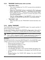
2.3.3 Current “LIMIT” LED
The AX Series Power Supplies provides the ability to limit the current
output. When the “limit” is reached, the power supply will switch to “current”
regulation to ensure the current output and drops the voltage regulation.
Setting a Current Limit:
• Short the output terminals, and adjust the current to the desired limit (you may need to have a little voltage for the current to flow).
The value of current flow will be displayed on the appropriate display.
• Turn the voltage output off and connect to the sample. As the voltage is increased, if the current reaches the set limit, the “LIMIT”
LED will turn on, and the current will no longer increase.
• The current limit may be overridden simply by increasing the current output manually.
DC Power Supply Models AX501, AX502 and AX503
9
2.3.4 “TRACKING” Switch (Models AX502 and AX503)
• “TRACKING” Mode
- This control enables two “0 to 30V” sources to be controlled in
series mode.
- When the “TRACKING” button is switched to ON, it sets up a
series connection between the “–” terminal of the MASTER
power supply and the “+” terminal of the SLAVE power supply.
The external terminals are used to connect the points in the
circuit to be powered.
- Only the voltage settings of the MASTER module cause the
voltages of the MASTER and SLAVE to vary proportionally.
• “TRACKING” LED
- When this LED is on, the “TRACKING” function has been activated.
2.3.5 Setting “TRACKING”
The SLAVE tracks as a % of the MASTER output. You need to set this %
before turning on the Tracking.
To set-up the Tracking, first set the MASTER voltage output, then set the
SLAVE output %. To set this %, simply adjust the SLAVE output voltage.
NOTE: Think of the SLAVE display as a % (10.0 = 100%, 5.0 = 50%,
20.0 = 200%). Once the SLAVE % is set, switching the Tracking ON
will cause the SLAVE to track the MASTER at the inputted %.
Example:
We want the SLAVE to Track the MASTER @ 30% of the MASTER output
voltage, and we want to Track starting @ 10.0V out of the MASTER.
•
•
•
•
•
•
Make sure the Tracking is OFF
Set the MASTER Voltage to 10.0V
Set the SLAVE to 30% (3.0V)
Turn the Tracking switch to ON
The MASTER will display 10.0V and the SLAVE will display 3.0V
As the MASTER is increased or decreased, the SLAVE will track
@ 30%
• During Tracking, the SLAVE LED displays the actual SLAVE
output voltage
10
DC Power Supply Models AX501, AX502 and AX503
In the previous setting, if the MASTER is increased to 20.0V, the SLAVE
will track and display 6.0V (30% of 20.0V).
If you want the SLAVE to track the MASTER @ 100%, set the SLAVE to
10.0 during the setup.
If you want the SLAVE to track the MASTER @ 200%, set the SLAVE to
20.0 during the setup (the output though is still limited to 30.0V).
2.3.6 Digital “LED” displays
A separate display allows you to view the voltage output (in green) and the
current output (in red) simultaneously for each 30V output.
The displays are 3-digit LED indicators with a resolution of 0.1V and
10mA.
2.3.7 Output Terminals
The female two-pin “+” and “–” safety terminals (Ø 4mm) are used to
connect the outputs to the points of the circuit to be powered by means of
safety leads only.
2.3.8 Ground Terminal
This terminal is directly linked internally to the ground on the AC power
plug.
It enables grounding of the circuit to be powered, if necessary.
Its male polarity and “green/yellow” color-coding will prevent any confusion
in the connections.
2.4
Interruption of the protective ground conductor, inside or outside the power supply, is prohibited.
Power Supply
The AX Series Power Supplies are factory configured at 115V ±10%;
50/60Hz. Consult the factory for changing to 220V supply.
DC Power Supply Models AX501, AX502 and AX503
11
CHAPTER 3
SPECIFICATIONS
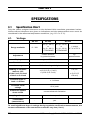
3.1 Specification Chart
Only the values assigned tolerances or the declared limits constitute guaranteed values.
Values without tolerances are given as indications and the measurement errors must be
considered in the reference temperature conditions, (e.g. 23° C ± 5° C).
4.1.
Voltage
Range available
AX 501
AX 502
AX 503
0 - 30V
2 x (0 - 30 V)
or
1 x (0 - 60 V)
+ TRACKING
2 x (0 - 30 V)
or
1 x (0 - 60 V)
+ TRACKING
+ output
2.7 V to 5.5 V
Adjustment
coarse and fine
by potentiometers
by
potentiometer
Display
green LEDs
none
Resolution
0.1 V
-
Accuracy
± 0.5 % of reading ± 1 digit
-
Stability if variation:
mains ± 10%
of the 0 to 2.5 A load
of the 0 to 5 A load
± (0.03 % R + 2 mV)
± (0.02 % R 5 mV)
-
± 4 mV
± (0.2 % R
+10 mV)
Residual ripple in
load < 1 mVrms
± 1 mVrms
Common mode
voltage
60 V peak
Protection against
short-circuit
current electronic limitation
Coupling of outputs
-
series or parallel
-
"TRACKING"
(master/slave)
-
yes
-
To avoid significant drops in voltage during regulation verification measurements, the
contact resistances of the connections must be very low (≤1mΩ).
12
DC Power Supply Models AX501, AX502 and AX503
4.2.
Current
Range available
AX 501
AX 502
AX 503
0 - 2.5 A
2 x (0 -2.5 A)
or
1 x (0 - 5 A)
2 x (0 -2.5 A)
or
1 x (0 - 5 A)
+ output 5 A
Adjustment
by potentiometer
none
Display
red LEDs
-
Resolution
10 mA
-
Accuracy
± 0.5 % of reading ± 1 digit
-
Output current
limitation
adjustable from 0 to 2.5 A
limited to
5A±5%
Residual current
< 22.5 mA
Indication of limitation
LED
Short-circuit protection
current limitation
Protection against
overheating
yes
3.2
General Specifications
Power Supply:115VAC ±10% Consult the factory for changing to 220VAC.
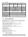
Display: Dual display - “VOLTAGE” in Green and “CURRENT” in Red;
7-segments; 0.56" (14.2mm) digit size.
Operating Temperature Range: 50° to 104°F (10° to 40°C)
Storage Temperature Range: -4° to 158°F (-20° to +70°C)
Temperature Coefficient: <0.1 x accuracy / °C
Operating Relative Humidity: <80% RH up to 104°F (40°C)
Electrical Field: nil
Magnetic Field: <40A/m
Dimensions (without knobs):
10.63 x 8.86 x 4.73" (270 x 225 x 120mm)
Weight:AX501: 8.8 lbs (4kg)
AX502: 9.9 lbs (4.5kg)
AX503: 13.2 lbs (6kg)
DC Power Supply Models AX501, AX502 and AX503
13
3.3
Safety Specifications
IEC 1010-1 (NF EN 61010-1 +A2: 1995) Class 1; Pollution Degree 2
Power supply outputs:Overvoltage Cat. 100V, CAT I
Max. Output Voltage:30.5VDC in normal mode
61.0VDC in series mode
Power supply inputs: Overvoltage CAT 300V, CAT II
Supply Current: 115V ±10%; 50/60Hz
Electromagnetic Compatibility:
EN50081-1 1992; EN50082-2 1998
*Specifications are subject to change without notice
14
DC Power Supply Models AX501, AX502 and AX503
CHAPTER 4
OPERATION
Before Using the Instrument
4.1
• When the required voltage and current parameter values are not
known, start by using the lowest values.
• Before disconnecting the leads of the circuit under test, make sure
that the power supply is turned off. This prevents the creation of
break or closure extra-currents which may melt the fuse at high
currents.
• Never exceed a total output of 60V peak in relation to the
ground.
• The instrument must be placed in a ventilated room. Do not
obstruct the ventilation holes.
• Before opening the instrument, disconnect it from all sources of
electric current and from the measuring circuits; make sure that
you are not charged with static electricity, which could irreparably
damage the instrument’s internal components.
4.2
WARNING: When the instrument is open, some of the internal
capacitors may be dangerous, even once the instrument has been
powered down.
In the event of faults or abnormal constraints, turn the instrument
OFF and do not use it until it has been checked.
Operating Instructions
• Check the label at the rear of the power supply to make sure that
the instrument is set to the AC line voltage compatible with your
setting.
• Connect the AC power cord to the supply.
• No connections should be made before powering up.
• Start up the power supply by pushing the Power On/Off button ON.
• To turn OFF the instrument, unplug the leads and push the Power
On/Off button OFF.
DC Power Supply Models AX501, AX502 and AX503
15
4.2.1 Using Independent Outputs
• Connect the AC power cord to the supply.
• Make sure that the voltage adjustment controls and current adjustment controls are turned to the left as far as they will go (minimum
voltage and current).
• Make sure that the “TRACKING” switch is in the OFF position.
• If necessary, connect the Earth/Ground terminal to the ground of
the circuit to be powered (to provide protection) and the Positive
and Negative terminals to the points of the circuit to be powered,
using the test cables.
• Check the quality and polarity of the connection to the sample.
• Press the Power On/Off button ON. The “LIMIT” LED should be
OFF.
• Set the voltage to be regulated by turning the voltage controls
to the right (increasing values). The voltage set point is then displayed.
• Adjust the value of the current limit by turning the current control
to the right (increasing values). The current value displayed is the
value of the output current. Short the output with a lead to adjust
the output current (See § 2.3.3).
• During use, when the output current reaches the limit current
value, the power supply automatically switches to “current” regulation mode, the “LIMIT” LED turns ON and the voltage is no
longer regulated.
4.2.2 Use of 2 Outputs in Parallel (AX502 and AX503)
To use 2 outputs in parallel (without “TRACKING”) up to 5A at 30V
max (see Fig. 4):
• Set the “TRACKING” switch to the OFF position.
• Set the 2 power supplies (MASTER and SLAVE) to the same
output voltage value.
• Link the “+” terminals together and the “–” terminals together using
short leads.
• Connect one of the two “+” terminals and one of the two “–” terminals to the circuit to be powered.
16
DC Power Supply Models AX501, AX502 and AX503
V max: 30V
Current max: 5.0A
ON
Sample
Figure 4
4.2.3 Use of 2 Outputs in Series (AX502 and AX503)
To use 2 outputs in series (without “TRACKING”) up to 60V at 2.5A
max (see Fig. 5):
•
Set the “TRACKING” switch to the OFF position.
•
Set the 2 power supplies (MASTER and SLAVE) to the same current
limitation value.
•
Use a lead to short the “+” terminal of one power supply to the “–”
terminal of the other power supply. Use the two “+” and “–” terminals
that remain free to make the connection with the circuit to be powered.
V max: 60V
Current max: 2.5A
ON
Sample
Figure 5
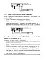
To use 2 outputs in series (with “TRACKING”), symmetrical ±30V
sources at 2.5A max (see Fig. 6):
Procedure: (for serial number > 105500MAV)
•
In sequence (power supply a then b), adjust the "current" potentiometers
to define identical limit currents.
•
Set the 2 Voltage potentiometers of the slave to the maximum (around
30.5V).
•
Press the "TRACKING" button ("ON", LED lit). When set to "ON", a
series connection between the "-" terminal of the "MASTER" power
supply and the "+" terminal of the "SLAVE" power supply is set.
•
The "MASTER" source is on the left (a); set the required initial voltage,
adjust it to the desired voltage.
•
The "SLAVE" source is on the right (b).
DC Power Supply Models AX501, AX502 and AX503
17
•
In this function, only the voltage controls of the "MASTER" source (a)
will be used from now on.
•
Connect the circuit to be powered (external terminals of the "MASTER"
and "SLAVE" power supplies).
•
The symmetrical "SLAVE" source (b) reacts to the "MASTER" source
(a) voltage variations by proportional "tracking" variations in absolute
values ("TRACKING" function).
NOTE: For the use of symmetrical voltages (e.g. ±15V), one of the
2 terminals (MASTER “–” or SLAVE “+”) will be connected to the
circuit to be powered (“0” point).
ON
Proportional Tracking from 0 - 30V
Current max: 2.5A
N Sample
Figure 6
NOTE: If the SLAVE source is taken outside its operating limits
(voltage or current) by the MASTER source, the corresponding
“LIMIT” LED lights up.
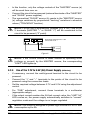
4.2.4 Use of the 2.7V to 5.5V (5A) Power Supply (AX503 Only)
•
If necessary, connect the earth/ground terminal to the circuit to be
powered.
•
Connect the “+” and “–” terminals to the points of the circuit to be
powered using the connection leads.
•
Set the required voltage between 2.7V and 5.5V using the adjustment
control.
•
For “FINE” adjustment, connect these terminals to a multimeter
(appropriate range).
•
If the output current reaches the 5A limit current value, the “LIMIT 5A”
LED comes on, the power supply automatically switches to “current”
regulation mode and the voltage is no longer regulated.
18
NOTE: This output is designed to power logic circuits at 3 or 5V with
consumption up to 5A.
DC Power Supply Models AX501, AX502 and AX503
CHAPTER 5
MAINTENANCE
5.1
Warning
• For maintenance use only specified factory replacement parts.
• To avoid electrical shock, do not attempt to perform any servicing
unless you are qualified to do so.
• To avoid electrical shock and/or damage, do not get water or other
foreign agents into the case. Turn the instrument OFF and disconnect the unit from all the circuits before opening the case.
5.2
Fuse Replacement
• The fuse protects the primary coil of the power supply transformer
against line voltage errors.
• Before opening the power supply to change the fuse, you must
disconnect the leads and power cord.
Only use a fuse of the following type: T 6.3A/250V for 115V
5.3Cleaning
• Disconnect the instrument, then clean it with a cloth lightly moistened with soapy water.
• Wipe with a clean dry cloth. Make sure it has completely dried
before use.
• Do not use abrasives or solvents.
5.4Storage
• To ensure proper operation, wait for the instrument to return to
normal measuring conditions if it has been stored in extreme environmental conditions for a long period of time.
An abrupt change in the ambient temperature may lead to condensation inside the instrument and cause short circuits.
Let the power supply stabilize in temperature before use.
DC Power Supply Models AX501, AX502 and AX503
19
Repair and Calibration
To ensure that your instrument meets factory specifications, we recommend
that it be scheduled back to our factory Service Center at one-year intervals
for recalibration, or as required by other standards or internal procedures.
For instrument repair and calibration:
You must contact our Service Center for a Customer Service Authorization
Number (CSA#). This will ensure that when your instrument arrives, it will be
tracked and processed promptly. Please write the CSA# on the outside of the
shipping container. If the instrument is returned for calibration, we need to
know if you want a standard calibration, or a calibration traceable to N.I.S.T.
(Includes calibration certificate plus recorded calibration data).
Ship To:
Chauvin Arnoux®, Inc. d.b.a. AEMC® Instruments
15 Faraday Drive
Dover, NH 03820 USA
Phone:(800) 945-2362 (Ext. 360)
(603) 749-6434 (Ext. 360)
Fax: (603) 742-2346 or (603) 749-6309
E-mail:[email protected]
(Or contact your authorized distributor)
Costs for repair, standard calibration, and calibration traceable to N.I.S.T. are
available.
NOTE: You must obtain a CSA# before returning any instrument.
Technical and Sales Assistance
If you are experiencing any technical problems, or require any assistance with
the proper operation or application of your instrument, please call, mail, fax or
e-mail our technical support team:
Chauvin Arnoux®, Inc. d.b.a. AEMC® Instruments
200 Foxborough Boulevard
Foxborough, MA 02035 USA
Phone:(800) 343-1391
(508) 698-2115
Fax: (508) 698-2118
E-mail:[email protected]
www.aemc.com
NOTE: Do not ship Instruments to our Foxborough, MA address.
20
DC Power Supply Models AX501, AX502 and AX503
Limited Warranty
The Model AX501, AX502 and AX503 are warranted to the owner for a period
of one year from the date of original purchase against defects in manufacture. This limited warranty is given by AEMC® Instruments, not by the distributor from whom it was purchased. This warranty is void if the unit has been
tampered with, abused or if the defect is related to service not performed by
AEMC® Instruments.
Full warranty coverage and product registration is available on our
website at www.aemc.com/warranty.html.
Please print the online Warranty Coverage Information for your records.
What AEMC® Instruments will do:
If a malfunction occurs within the one-year period, you may return the instrument
to us for repair, provided we have your warranty registration information on file
or a proof of purchase. AEMC® Instruments will, at its option, repair or replace
the faulty material.
REGISTER ONLINE AT:
www.aemc.com
Warranty Repairs
What you must do to return an Instrument for Warranty Repair:
First, request a Customer Service Authorization Number (CSA#) by phone
or by fax from our Service Department (see address below), then return the
instrument along with the signed CSA Form. Please write the CSA# on the
outside of the shipping container. Return the instrument, postage or shipment
pre-paid to:
Ship To:
Chauvin Arnoux®, Inc. d.b.a. AEMC® Instruments
15 Faraday Drive • Dover, NH 03820 USA
Phone:(800) 945-2362 (Ext. 360)
(603) 749-6434 (Ext. 360)
Fax: (603) 742-2346 or (603) 749-6309
E-mail:[email protected]
Caution: To protect yourself against in-transit loss, we recommend you insure
your returned material.
NOTE: You must obtain a CSA# before returning any instrument.
DC Power Supply Models AX501, AX502 and AX503
21
05/14
99-MAN 100252 v9
Chauvin Arnoux®, Inc. d.b.a. AEMC® Instruments
15 Faraday Drive • Dover, NH 03820 USA • Phone: (603) 749-6434 • Fax: (603) 742-2346
www.aemc.com