1
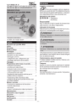
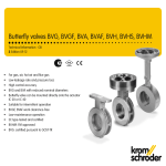
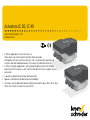
Actuators IC 20, IC 40
Technical Information · GB
3 Edition 04.14
• IC 20 for applications with continuous or
three-point step control and Automatic/Manual m
ode
changeover for easy commissioning, IC 20..E with electronic positioning
function and adjustable behaviour in the event of cable discontinuity
• IC 40 for complex applications with programmable functions for flexible
adjustment to the process, with statistics and fault history to support service
personnel
• A position indicator that can be read externally
• Spacious connection chamber for ease of installation
• Actuators can be delivered ready installed on butterfly valves BVG, BVGF, BVA,
BVAF, BVH, BVHS or linear flow control VFC
Contents
Actuators IC 20, IC 40 . . . . . . . . . . . . . . . . . . . . . . . . . . . . . . 1
Contents . . . . . . . . . . . . . . . . . . . . . . . . . . . . . . . . . . . . . . . . 2
1 Application . . . . . . . . . . . . . . . . . . . . . . . . . . . . . . . . . . . . 4
1.1 Examples of application . . . . . . . . . . . . . . . . . . . . . . . . . . 7
1.1.1 IC 20, continuous control . . . . . . . . . . . . . . . . . . . . . . . . . . . . 7
1.1.2 IC 20..E, continuous control . . . . . . . . . . . . . . . . . . . . . . . . . . 7
1.1.3 IC 20, modulating control with burner control unit BCU 370 8
1.1.4 IC 40, staged control . . . . . . . . . . . . . . . . . . . . . . . . . . . . . . . 9
1.1.5 IC 40, staged control with three burner capacity levels . . . 9
1.1.6 IC 40, continuous control by three-point step signal . . . . . 10
1.1.7 IC 40, staged control with pre-purge . . . . . . . . . . . . . . . . . . 11
1.1.8 IC 40, continuous control with defined ignition position . . 12
1.1.9 IC 40, hot-air compensation . . . . . . . . . . . . . . . . . . . . . . . . 13
1.1.10 IC 40, staged control with online adjustment of the
burner capacity . . . . . . . . . . . . . . . . . . . . . . . . . . . . . . . . . . . . . . 14
2 Certification . . . . . . . . . . . . . . . . . . . . . . . . . . . . . . . . . . .
3 IC 20 function . . . . . . . . . . . . . . . . . . . . . . . . . . . . . . . . . .
3.1 IC 20..T Connection diagram . . . . . . . . . . . . . . . . . . . . .
3.2 IC 20..E connection diagram . . . . . . . . . . . . . . . . . . . . .
15
16
17
18
3.2.1 Continuous control . . . . . . . . . . . . . . . . . . . . . . . . . . . . . . . 18
3.2.2 2-point step control . . . . . . . . . . . . . . . . . . . . . . . . . . . . . . 18
3.3 IC 20..E Display . . . . . . . . . . . . . . . . . . . . . . . . . . . . . . . . 19
3.3.1 In Manual mode . . . . . . . . . . . . . . . . . . . . . . . . . . . . . . . . . 19
3.3.2 Low-fire/High-fire rate adjustment (in Manual mode
only) . . . . . . . . . . . . . . . . . . . . . . . . . . . . . . . . . . . . . . . . . . . . . . . . 19
3.3.3 Warnings and faults . . . . . . . . . . . . . . . . . . . . . . . . . . . . . . 19
3.4 IC 20..E DIP switch . . . . . . . . . . . . . . . . . . . . . . . . . . . . 20
4 IC 40 function . . . . . . . . . . . . . . . . . . . . . . . . . . . . . . . . . . 21
4.1 Operating modes . . . . . . . . . . . . . . . . . . . . . . . . . . . . . 22
4.2 Standard and analogue operating modes . . . . . . . . 22
4.3 Closed, low-fire rate, intermediate and open position 22
4.4 Running times . . . . . . . . . . . . . . . . . . . . . . . . . . . . . . . 23
4.5 Standard operating modes 1 – 12 . . . . . . . . . . . . . . . . 24
4.5.1 2-point operation . . . . . . . . . . . . . . . . . . . . . . . . . . . . . . . . . 24
IC 20, IC 40 · Edition 04.14
4.5.2 2-point operation with flame proving period . . . . . . . . . .
4.5.3 2-step operation with one or two digital inputs . . . . . . . .
4.5.4 2-step operation with two digital inputs . . . . . . . . . . . . . .
4.5.5 3-point step operation . . . . . . . . . . . . . . . . . . . . . . . . . . . .
4.5.6 3-step operation with one or two digital inputs . . . . . . . .
4.5.7 2-point operation with switchover of the adjustment
angle for the “open” position . . . . . . . . . . . . . . . . . . . . . . . . . . .
4.5.8 2-point operation with input-dependent adjustment
angle for the “open” position . . . . . . . . . . . . . . . . . . . . . . . . . . .
4.5.9 2-point operation with switchover of the running times .
4.5.10 3-point step operation with running time fractions . . . .
4.5.11 3-step operation with two digital inputs . . . . . . . . . . . . . .
4.5.12 3-point step operation with low position . . . . . . . . . . . . .
25
26
28
29
30
32
34
35
36
38
39
4.6 Analogue operating modes 21 – 27 . . . . . . . . . . . . . . 40
4.6.1 2-point operation . . . . . . . . . . . . . . . . . . . . . . . . . . . . . . . . . 40
4.6.2 2-point operation with switchover of the adjustment
angle for the “open” position . . . . . . . . . . . . . . . . . . . . . . . . . . . 42
4.6.3 2-point operation with input-dependent adjustment
angle for the “open” position . . . . . . . . . . . . . . . . . . . . . . . . . . . 44
4.6.4 2-point operation with switchover of the running times . 45
4.6.5 2-point operation with characteristic curve switchover I . 47
4.6.6 2-point operation with characteristic curve switchover II . 49
4.6.7 2-step operation with two digital inputs and variable
adjustment angle . . . . . . . . . . . . . . . . . . . . . . . . . . . . . . . . . . . . . 51
4.6.8 Safety closing function . . . . . . . . . . . . . . . . . . . . . . . . . . . . 52
4.7 Parameters . . . . . . . . . . . . . . . . . . . . . . . . . . . . . . . . . . 53
4.7.1 Parameter sets . . . . . . . . . . . . . . . . . . . . . . . . . . . . . . . . . . . 54
4.7.2 Factory default parameters . . . . . . . . . . . . . . . . . . . . . . . . 56
4.8 Inputs . . . . . . . . . . . . . . . . . . . . . . . . . . . . . . . . . . . . . . . 57
4.8.1 Digital . . . . . . . . . . . . . . . . . . . . . . . . . . . . . . . . . . . . . . . . . . 57
4.8.2 Analogue . . . . . . . . . . . . . . . . . . . . . . . . . . . . . . . . . . . . . . . 57
4.9 Outputs . . . . . . . . . . . . . . . . . . . . . . . . . . . . . . . . . . . . . 59
4.10 Manual mode . . . . . . . . . . . . . . . . . . . . . . . . . . . . . . . 60
4.10.1 Direct position preset . . . . . . . . . . . . . . . . . . . . . . . . . . . . . 60
4.10.2 Simulate inputs . . . . . . . . . . . . . . . . . . . . . . . . . . . . . . . . . 60
4.11 Statistics . . . . . . . . . . . . . . . . . . . . . . . . . . . . . . . . . . . . . 61
4.11.1 Counters . . . . . . . . . . . . . . . . . . . . . . . . . . . . . . . . . . . . . . . 61
▼
= To be continued
2
Contents
4.11.2 Measured values . . . . . . . . . . . . . . . . . . . . . . . . . . . . . . . . 61
4.11.3 Resetting statistics . . . . . . . . . . . . . . . . . . . . . . . . . . . . . . . 61
4.11.4 Resetting a signal . . . . . . . . . . . . . . . . . . . . . . . . . . . . . . . . 61
4.12 IC 40 connection diagram . . . . . . . . . . . . . . . . . . . . . 62
4.13 Display . . . . . . . . . . . . . . . . . . . . . . . . . . . . . . . . . . . . . 63
4.13.1 During operation . . . . . . . . . . . . . . . . . . . . . . . . . . . . . . . . 63
4.13.2 Warnings and faults . . . . . . . . . . . . . . . . . . . . . . . . . . . . . 63
4.14 Relay outputs RO 1 and RO 2 function . . . . . . . . . . . . 65
5 Replacement possibilities for actuators . . . . . . . . . . . . 66
5.1 GT 31 is to be replaced with IC 20 . . . . . . . . . . . . . . . . 66
5.2 GT 31 is to be replaced with IC 40 . . . . . . . . . . . . . . . . . 67
5.3 M5/M6 is to be replaced with IC 40 . . . . . . . . . . . . . . 68
6 Selection . . . . . . . . . . . . . . . . . . . . . . . . . . . . . . . . . . . . . 69
6.1 IC 20, IC 40 . . . . . . . . . . . . . . . . . . . . . . . . . . . . . . . . . . 69
6.1.1 Type code . . . . . . . . . . . . . . . . . . . . . . . . . . . . . . . . . . . . . . . 69
7 Project planning information . . . . . . . . . . . . . . . . . . . . . 70
7.1 Electrical connection . . . . . . . . . . . . . . . . . . . . . . . . . . . 70
7.1.1 Cable selection . . . . . . . . . . . . . . . . . . . . . . . . . . . . . . . . . . .
7.1.2 IC 20 . . . . . . . . . . . . . . . . . . . . . . . . . . . . . . . . . . . . . . . . . . .
7.1.3 IC 20..E . . . . . . . . . . . . . . . . . . . . . . . . . . . . . . . . . . . . . . . . .
7.1.4 IC 40 . . . . . . . . . . . . . . . . . . . . . . . . . . . . . . . . . . . . . . . . . . .
70
70
70
70
7.2 Feedback potentiometer . . . . . . . . . . . . . . . . . . . . . . . 72
7.3 Installation . . . . . . . . . . . . . . . . . . . . . . . . . . . . . . . . . . . 73
7.4 IC 40 commissioning . . . . . . . . . . . . . . . . . . . . . . . . . . 73
8 Accessories . . . . . . . . . . . . . . . . . . . . . . . . . . . . . . . . . . 74
8.1 IC 20, IC 40
Heat deflectors . . . . . . . . . . . . . . . . . . . . . . . . . . . . . . . . . . 74
8.2 Adapter set for mounting an actuator IC 20, IC 40
onto a butterfly valve DKL, DKG . . . . . . . . . . . . . . . . . . . . . 74
8.3 IC 20, IC 40 “single application”
attachment set . . . . . . . . . . . . . . . . . . . . . . . . . . . . . . . . . . 74
8.4 IC 20 potentiometer installation set . . . . . . . . . . . . . . 75
8.5 BCSoft® . . . . . . . . . . . . . . . . . . . . . . . . . . . . . . . . . . . . . . . . . . . . . . . . . 75
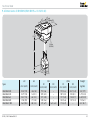
9 Technical data . . . . . . . . . . . . . . . . . . . . . . . . . . . . . . . . . 76
9.1 IC 20, IC 20..E . . . . . . . . . . . . . . . . . . . . . . . . . . . . . . . . 76
9.1.1 IC 20 . . . . . . . . . . . . . . . . . . . . . . . . . . . . . . . . . . . . . . . . . . . 76
9.1.2 IC 20..E . . . . . . . . . . . . . . . . . . . . . . . . . . . . . . . . . . . . . . . . . 76
9.2 IC 40 . . . . . . . . . . . . . . . . . . . . . . . . . . . . . . . . . . . . . . . . 77
9.3 Running times and torques . . . . . . . . . . . . . . . . . . . . . 78
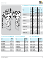
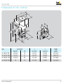
9.4 Dimensions of IBG/IBA (BVG/BVA + IC 20/IC 40) . . . . 79
9.4.1 With full bore = nominal diameter . . . . . . . . . . . . . . . . . . . 79
9.4.2 With 1 × reduced bore . . . . . . . . . . . . . . . . . . . . . . . . . . . . 79
9.4.3 With 2 × reduced bore . . . . . . . . . . . . . . . . . . . . . . . . . . . . 79
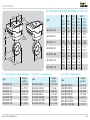
9.5 Dimensions of IBGF/IBAF (BVGF/BVAF + IC 20/IC 40) 80
9.5.1 With full bore = nominal diameter . . . . . . . . . . . . . . . . . . . 80
9.5.2 With 1 × reduced bore . . . . . . . . . . . . . . . . . . . . . . . . . . . . 80
9.5.3 With 2 × reduced bore . . . . . . . . . . . . . . . . . . . . . . . . . . . . 80
9.6 Dimensions of IBH/IBHS (BVH/BVHS + IC 20/IC 40) . . 81
9.7 Dimensions IFC, IFC..T (VFC + IC 20/IC 40) . . . . . . . . . 82
10 Maintenance cycles . . . . . . . . . . . . . . . . . . . . . . . . . . . 83
11 Glossary . . . . . . . . . . . . . . . . . . . . . . . . . . . . . . . . . . . . . 84
11.1 Start fuel flow rate . . . . . . . . . . . . . . . . . . . . . . . . . . . . 84
11.2 Positions . . . . . . . . . . . . . . . . . . . . . . . . . . . . . . . . . . . . 84
11.3 Adjustment angle for the “open” position . . . . . . . . . 84
12 Legend . . . . . . . . . . . . . . . . . . . . . . . . . . . . . . . . . . . . . 85
Feedback . . . . . . . . . . . . . . . . . . . . . . . . . . . . . . . . . . . . . . 86
Contact . . . . . . . . . . . . . . . . . . . . . . . . . . . . . . . . . . . . . . . 86
8.5.1 Opto-adapter PCO 200 . . . . . . . . . . . . . . . . . . . . . . . . . . . . 75
8.5.2 Bluetooth adapter PCO 300 . . . . . . . . . . . . . . . . . . . . . . . . 75
IC 20, IC 40 · Edition 04.14
3
1 Application
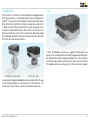
IC 20
The actuators IC 20 and IC 40 are designed for all applications
that require precise, controlled rotary movement between 0°
and 90°. They can be mounted directly onto the butterfly valves
BVG, BVGF, BVA, BVAF, BVH, BVHS or linear flow control VFC
in order to control the gas and air flow rates on gas burners.
Actuators and butterfly valves BVG, BVGF, BVA, BVAF, BVH,
BVHS or linear flow control VFC can also be delivered ready
assembled as butterfly valves with actuator IBG, IBGF, IBA, IBAF,
IBH, IBHS or linear flow control IFC.
IC 20 is ontrolled by a continuous signal or three-point step
signal. The Automatic/Manual mode changeover and the position indicator that can be read externally assist in the setting of
the infinitely adjustable switching cams upon commissioning.
This enables precise settings even in the low-fire rate range.
IBG 80 (IC 20 + BVG 80)
IFC (IC 20 + VFC)
An optional integrated feedback potentiometer offers the option of monitoring the current position of the actuator. This
checking function can be used in automation processes.
IC 20, IC 40 · Edition 04.14
4
Application
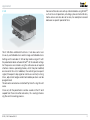
IC 40
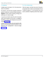
Service technicians can call up statistical data using BCSoft®,
such as hours of operation, actuating cycles and a faul history.
Some values can also be set to zero, for example to record
data over a specific period of time.
The IC 40 offers additional functions. It can be used in continuously-controlled burners and in stage-controlled burners.
Settings on the actuator IC 40 can be made using a PC with
the parameterization software BCSoft®. All the relevant settings
for the process are made using the software via an optical
interface. Various operating modes, which may be modified,
are stored in the unit. In addition, the control type (two-point
signal, three-point step signal or continuous control), running
times, adjustment angles and intermediate positions can be
programmed.
The actuator can also be controlled “by hand” using the software.
Once set, all the parameters can be saved on the PC and
copied from there into other actuators, thus saving time during the commissioning process.
IC 20, IC 40 · Edition 04.14
5
Application
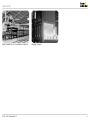
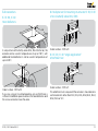
IC 20 with BVG 80
Roller hearth kiln in the ceramics industry
IC 20, IC 40 · Edition 04.14
Forging furnace
6
Application
1.1 Examples of application
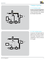
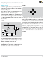
1.1.1 IC 20, continuous control
For processes that require high temperature accuracy and low circulation in the
furnace. The actuator IC 20 is controlled
by a three-point step controller.
Threepoint
step
VAG
M
IC 20 + BVA
BVA
1.1.2 IC 20..E, continuous control
For processes that require high temperature accuracy and low circulation
in the furnace. The actuator IC 20..E is
controlled by a 4 – 20 mA, 0 – 20 mA or
0 – 10 V signal.
VAG
4–20 mA
M
IC 20..E
IC 20, IC 40 · Edition 04.14
BVA
7
Application > Examples of application
R..
M
S4
S3
S1
S10
15 16
0°
6 7 8 11 12 13
90°
1 2 3 4 5
0° ➔ 90°
PE
90° ➔ 0°
IC 20
S2
S11
1 7 1 8 1 9 20
max. 0,5 W
PE
N (L2)
L1 (L1)
3PS
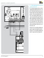
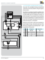
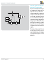
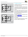
1.1.3 IC 20, modulating control with burner
control unit BCU 370
This connection option can be used on
modulating forced draught burners. The
BCU 370 controls the fan and moves the
butterfly valve to pre-purge and ignition
position. After pre-purge and burner
start, the controller enable signal is issued to an external three-point step controller which positions the butterfly valve
in accordance with the capacity demand.
The “Close contact” (90° ➔ 0°) of the external three-point step controller (3PS)
can be connected to terminal 26 or 27
of the BCU 370.
Terminal 26: the controller operates between the open and ignition positions.
Terminal 27: the controller operates between the open and closed positions.
32 31 30 29 28 27 26 25
90° ➔ 0°
0° ➔ 90°
r
BCU 370
IC 20, IC 40 · Edition 04.14
8
Application > Examples of application
Twopoint
step
VAG +
VAS 1
M
IC 40 + BVA
PLC
BVA
VAG +
VAS 1
M
IC 40 + BVA
IC 20, IC 40 · Edition 04.14
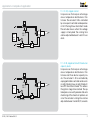
1.1.4 IC 40, staged control
For processes that require a homogeneous temperature distribution in the
furnace. The actuator IC 40 is controlled
by a two-point controller and operates
in On/Off or High/Low intermittent mode.
The actuator closes when the voltage
supply is interrupted. The running time
can be adjusted between 5 and 25 seconds.
BVA
1.1.5 IC 40, staged control with three burner
capacity levels
For processes that require a homogeneous temperature distribution in the
furnace and three burner capacity levels. The actuator IC 40 is controlled by
a programmable controller and works
in High/Medium/Low or High/Medium/
Low/Off intermittent mode. This allows
the ignition stage to be started. The optional pressure switch provides fail-safe
monitoring of the maximum pilot air volume. The actuator running time can be
adjusted between 5 and 50 (75) seconds.
9
Application > Examples of application
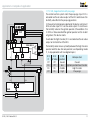
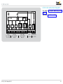
1.1.6 IC 40, continuous control by three-point step signal
The actuator IC 40 is controlled by the three-point step controller
3PS and moves the butterfly valve BVA to the ignition position.
The burner starts.
Once the burner is operating, the operation signalling contact
of the burner control unit BCU 460 closes. The BCU issues the
controller enable signal to the temperature controller. The
butterfly valve opens or closes between the low-fire and highfire rate positions depending on the capacity demand of the
burner. When the three-point step signal is disconnected, the
butterfly valve stops at its current position.
If both inputs on the IC 40 (DI 1 and DI 2) are actuated after the
burner has been shut down, the butterfly valve closes further
than the low-fire rate position (see Operating mode 12, 3-point
step operation with low position)
L1, N, PE
P
3PS
3
5
PLC
4
µC
BCU 460
18
19
16
17
12
V1
9
VAG
BIO/
BIC
DI 1 DI 2
IC 40 position
Valve position
Off Off
Idle/Stop
Idle
On Off Open to high position Open to high-fire rate
Off On Close to middle position Close to low-fire rate
On On
low
Valve closes further
DI 2
DI 1 4
IC 40
µC
7
M
BVA
IC 20, IC 40 · Edition 04.14
10
Application > Examples of application
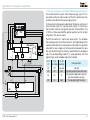
1.1.7 IC 40, staged control with pre-purge
The central control system starts the pre-purge. Input DI 2 is
actuated via the air valve output of the BCU and moves the
butterfly valve BVA to the pre-purge position.
In the event of a temperature demand, the burner control unit
BCU actuates input DI 1 via the valve output V1 and moves
the butterfly valve to the ignition position. (Precondition: the
IC 40 must have reached the ignition position on the instant
of ignition.) The burner starts.
To activate the high-fire rate, DI 2 is actuated via the air valve
output on terminal 26 of the BCU.
The butterfly valve moves cyclically between the high-fire rate
position and the low-fire rate position (see Operating mode
11, 2-step operation with two digital inputs).
L1, N, PE
P
PLC
P
A
22 3
5
23
4
BCU 460..L
µC
18
19
16
17
12
V1
26
9
VAG
BIO/
BIC
DI 1
4
IC 40
DI 1/
DI 2/
V1 air Valve
Off
Off
On
Off
On
On
Off
On
IC 40
position
closed
low
middle
high
Valve position
Closed
Ignition position/low-fire rate
High-fire rate
Pre-purge
DI 2
7
M
BVA
IC 20, IC 40 · Edition 04.14
11
Application > Examples of application
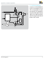
1.1.8 IC 40, continuous control with defined ignition position
The central control system starts the pre-purge. Input DI 2 is
actuated via the air valve output of the BCU and moves the
butterfly valve BVA to the pre-purge position.
In the event of a temperature demand, the burner control unit
BCU actuates input DI 1 via the valve output V1 and moves
the butterfly valve to the ignition position. (Precondition: the
IC 40 must have reached the ignition position on the instant
of ignition.) The burner starts.
The BCU actuates DI 2 via the air valve output. This enables
the analogue input AI on the actuator IC 40. Depending on the
capacity demand of the temperature controller, the butterfly
valve BVA moves steplessly to the position between the lowfire rate and the high-fire rate as specified by the analogue
input AI (see Operating mode 27, 2-step operation with two
digital inputs and variable adjustment angle).
L1, N, PE
P
mA
PLC
P
22 3
5
4
BCU 460..L
µC
18
19
16
17
12
V1
26
9
VAG
BIO/
BIC
DI 1
4
AI
DI 2
7
DI 1/
DI 2/
IC 40
air valve position
V1
Off
Off
closed
On
Off
low
On
On
AI
Off
On
high
Valve position
Closed
Ignition position/low-fire rate
Any position between ignition
position and pre-purge
Pre-purge/high-fire rate
µC
18
IC 40
M
BVA
IC 20, IC 40 · Edition 04.14
12
Application > Examples of application
1.1.9 IC 40, hot-air compensation
For processes in which preheated combustion air at a temperature of up to
450°C must be controlled. In this example, the actuator IC 40 is regulated by a
two-point controller to adjust the burner
capacity. It runs in High/Low intermittent
mode. The running time can be adjusted
between 5 and 25 seconds.
GIK
WPS
VAG +
VAS 1
M
Two
point
IC 40 +
BVH
IC 20, IC 40 · Edition 04.14
13
Application > Examples of application
4–20 mA
PLC
VAG +
VAS 1
M
IC 40 + BVA
IC 20, IC 40 · Edition 04.14
BVA
1.1.10 IC 40, staged control with online
adjustment of the burner capacity
For processes that require a homogeneous temperature distribution and high
temperature accuracy in the furnace.
If only a low heat output is required, for
example to maintain the temperature
in the furnace, the burner can continue
to run in intermittent mode. The adjustment angle of the valve is reduced by the
analogue input (4 – 20 mA) of the actuator and the burner capacity is therefore
lowered. This ensures uniform temperature distribution even with a low burner
capacity.
This function of the actuator IC 40 can
also be used in the ceramics industry to
correct the lambda value or for temperature compensation purposes in hot-air
applications.
14
2 Certification
EC type-tested and certified
Meets the requirements of the
– Low Voltage Directive (2006/95/EC) on the basis of
EN 60730-1,
– Electromagnetic Compatibility Directive (2004/108/EC).
Approval for Russia
Certified by Gosstandart pursuant to GOST R.
Approved by Rostekhnadzor (RTN).
Scan of the approval for Russia (RUS), see www.docuthek.com
➔ Elster Kromschröder ➔ Kromschröder, LBE ➔ Products ➔ 03
Valves and butterfly valves ➔ Actuators IC 20, IC 40 ➔ Type
of document: Certificate ➔ IC B00069 (nationales Zertifikat
Russland) (RUS)
IC 20, IC 40 · Edition 04.14
15
3 IC 20 function
The actuator IC 20 moves towards 0° or 90° if it is energized
electrically at the related terminal. If the voltage is disconnected,
the actuator stops at the current position. A high holding torque
when de-energized renders additional braking elements superfluous. The low-fire and high-fire rates are adjusted using
two infinitely adjustable switching cams (S3, S4). An optional
integrated feedback potentiometer offers the option of monitoring the current position of the actuator.
The actuator IC 20 is optimally tailored to the Kromschröder
butterfly valves BVG, BVGF, BVA, BVAF, BVH, BVHS or linear
flow control VFC.
Automatic/Manual mode
Switchover between Automatic and Manual mode facilitates
setting of the infinitely adjustable switching cams during commissioning. This enables precise settings even in the low-fire
rate range.
The switching point is set directly on the cams with a screwdriver.
External devices can be activated or intermediate positions
can be checked via two additional, floating, infinitely adjustable switches.
IC 20..E
In normal operation, input “OK” is supplied with voltage. The
setpoint device issues an actuating signal (0 (4) – 20 mA,
0 – 10 V). The current signal corresponds to the adjustment
angle to be approached (e.g. with a 0 – 20 mA signal, 10 mA
correspond to a valve angle of 45°). The minimum and maximum adjustment angles can be set manually using the keys.
The hysteresis can be adjusted on a potentiometer to suppress
interference in the input signal.
The IC 20..E offers the option of monitoring the current position
of the actuator via the continuous 4 – 20 mA output signal.
IC 20, IC 40 · Edition 04.14
16
IC 20 function
3.1 IC 20..T Connection diagram
S4
R..
M
S3
S1
S10
S2
S11
PE
1 2 3 4 5
90° ➔ 0°
0° ➔ 90°
L1 L1 L1 N
IC 20, IC 40 · Edition 04.14
6 7 8 11 12 13
15 16
1 7 1 8 1 9 20
90°
0°
IC 20
See page 70 (Project planning information).
See page 76 (Technical data).
max. 0,5 W
17
IC 20 function
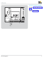
3.2 IC 20..E connection diagram
M
See page 70 (Project planning information).
See page 76 (Technical data).
µC
R
ON
S3
R
R
1 23456
S1
S10
S2
A
A
IC 20..E PE
6 7 8 11 12 13
90°
0°
OK
90° ➔ 0°
0° ➔ 90°
L1 L1 L1 N L1
15 16
M
+
+
1 7 1 8 1 9 20
IN
OUT
0(4)–20 mA
0–10 V
1 2 3 4 5
D
D
µC
R
ON
S3
R
R
1 23456
S1
S10
S2
A
A
OK
N L1
L1
IC 20, IC 40 · Edition 04.14
6 7 8 11 12 13
15 16
90°
0°
IC 20..E PE
1 2 3 4 5
+
D
D
+
1 7 1 8 1 9 20
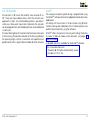
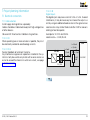
3.2.2 2-point step control
Connect voltage to terminals 1 and 3. Set
the DIP switch to 2-point step control, see
page 20 (IC 20..E DIP switch).
If an input signal is applied to terminal
5 (OK), the actuator opens. If no input
signal is applied to terminal 5, the actuator closes.
Terminals 17 and 18 for continuous
control are not required in the case of
2-point control.
OUT
4–20 mA
S4
3.2.1 Continuous control
Following successful modulation enable
via terminal 5 (OK), the actuator reacts to
the setpoint specification (0 (4) – 20 mA,
0 – 10 V) via terminals 17 and 18.
The pre-purge and ignition positions are
controlled via terminals 1 and 2.
4–20 mA
S4
18
IC 20 function
3.3 IC 20..E Display
3.3.1 In Manual mode
Blue LED
Red LED
Operating state
On
Off
Manual mode
Flashing
Flashing
Calibration (in Manual mode only)
3.3.2 Low-fire/High-fire rate adjustment (in Manual mode only)
Blue LED
Red LED
On
On for 0.5 s
Off for ≤ 0.5 s
Off
Operating state
Min. value ≥ max. value*
Min. or max. setting accepted
* Value will only be accepted, if the Min. or Max. button is pressed for another three seconds.
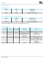
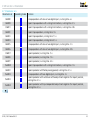
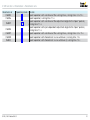
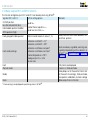
3.3.3 Warnings and faults
Blue LED
Red LED
Warning/fault
Off
Flashing light (1×)
Warning
Off
Flashing light (2×)
Warning
Off
Flashing light (3×)
Warning
Flashing light (1×)
Permanent light
Fault
Flashing light (2×)
Permanent light
Fault
IC 20, IC 40 · Edition 04.14
Description
Cause
The device is in 4 – 20 mA mode, - Cable discontinuity on the 4 – 20 mA setthe input signal is < 3 mA
point input
Many changes of direction, input
- Hysteresis set too small
signal oscillates
- Device programming error (min. and
Control range < 1°
max. setting)
- Control range < 1° (cams overlapping),
Calibration not successful
motor defective, gear defective, potentiometer defective
Internal fault
- Unit defective
19
ON
1 2 3 4 5 6
ICON20 function
OFF 1 2
Choosing
ON
1 2
1 2
ON
OFF
ON
OFF 1 2
OFF
ON 1 2
1 2
ON
OFF
ON
OFF 1 2
OFF
ON 1 2
1 2
ON
OFF
ON
OFF 1 2
OFF
ON 1 2
3 4 5 6
3 4 5 6
3 4 5 6
3 4 5 6
3 4 5 6
3 4 5 6
3 4 5 6
3 4 5 6
3 4 5 6
1 2 3 4 5 6
OFF
ON
ON
OFF
1 2 3in the
4 5event
6
Behaviour
OFF
ON 1 2 3 4 5 6
1 2 3 4 5 6
OFF
ON
ON
OFF 1 2 3 4 5 6
OFF
ON
OFF
ON
ON
OFF
OFF
ON
OFF
ON
ON
OFF
OFF
ON
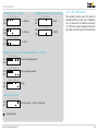
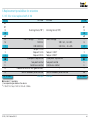
4 – 20 mA
0 – 20 mA
4 – 20 mA
0 – 20 mA
0 – 10 V
0 – 20 mA
0 – 10 V
50 Ω
0 – 10 V
50 Ω
1 2 3 4 5 6
ON
0 – 10 V
OFF
Load impedance of the current input
1 2 3 4 5 6
ON
50 Ω
OFF
1 2 3 4 5 6
ON
250 Ω
OFF
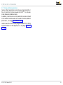
3.4 IC 20..E DIP switch
The setpoint device input, the load impedance of the current input, the behaviour in the event of cable discontinuity
(4 – 20 mA) or 2-point step control are set
by means of a DIP switch on the actuator.
1 2 3 4 5 6
ON
OFF
1 2 3 4 5 6
250 Ω
Ω discontinuity
ON(4 – 20 mA)
of50cable
OFF
250 Ω
Moves to closed position
250 Ω
1 2 3 4 5 6
ON
OFF
11 22 33 44 55 66
Moves to open position
1 2 3 4 5 6
1 2 3 4 5 6
ON
11 22 33 44 55 66
OFF
Stops
1 2 3 4 5 6
11 22 33 44 55 66
OFF
ON
ON
2-point
step control
OFF
OFF 1 2 3 4 5 6
ON
OFF
ON
4 – 20 mA
the
5 6signal
3 4input
3 4 5 6
0 – 20 mA
OFF
1 2 3 4 5 6
Burner control: On/Off or High/Low
OFF
= Switch position
IC 20, IC 40 · Edition 04.14
20
4 IC 40 function
The actuator IC 40 moves the butterfly valve towards 0° or
90°. There are 4 possible positions which the actuator can
approach in steps. Any intermediate position is possible in
continuous three-point step mode. Optionally, the actuator
can also approach any intermediate position via an additional
current input.
The slow flashing blue LED indicates that the motor of actuator
IC 40 is moving. The position indicator on the housing indicates
the opening angle. Further visualization and operation are
performed on a PC using the Kromschröder BCSoft® software.
BCSoft®
The sequence of opening and closing is programmed using
the BCSoft® software and can be adapted individually to any
application.
All settings for the actuator IC 40 are made using BCSoft®.
Commissioning and calibration of the “closed” position are
performed conveniently using the software.
BCSoft® offers the option of moving and setting the butterfly valve in Manual mode via the actuator, see page 60
(Manual mode).
A detailed manual is available for the BCSoft® software:
http://www.docuthek.com
Products 03 Valves and butterfly valves
Actuators IC 20, IC 40.
IC 20, IC 40 · Edition 04.14
21
IC 40 function
4.1 Operating modes
The operating mode is responsible for the setting properties
of the IC 40.
The running times and dwell positions of the actuator are stored
in the various operating modes but can be reprogrammed
at any time using BCSoft® (if mounted on BVA, BVG or BVH).
The actuator operates in continuous and intermittent mode
with various adjustment angles for the “open” position. The adjustment angles for the “open” position indicate the approach
position of the actuator in the case of intermittent operation.
They can be changed in BCSoft®.
The corresponding operating modes are displayed in BCSoft®
as flowcharts by way of example to visualize the opening/
closing behaviour of the actuator.
4.2 Standard and analogue operating modes
In the standard operating modes, two digital inputs (DI 1 and
DI 2) of the actuator are pre-assigned at the works as universal
inputs. If a voltage of 24 V DC or 100 – 230 V AC is applied to
the input, this is recognized as “On” signal (positive logic). It
is not necessary to set or readjust the voltage magnitude or
voltage type.
In the analogue operating modes, an additional input (AI) is
assigned for the actuator. If an actuator IC 40..A with 4 – 20 mA
analogue input is connected (option), further operating modes
are available in addition to the standard operating modes. The
actuator can approach corresponding intermediate positions
via a current signal to the additional input, see page 58
(Priority and running time in operating modes 1 – 10).
IC 20, IC 40 · Edition 04.14
4.3 Closed, low-fire rate, intermediate and open
position
Depending on the set operating mode, there are 4 positions which the actuator can approach:
Closed = 0° = 0%,
Low = low-fire rate position,
Middle = intermediate position,
High = open position.
The positions not used by the operating mode are barred in
this case.
The “closed position” is always the calibrated zero position
of the device and cannot be readjusted. The other positions
can be defined on site.
Basically, the following parameter limits must be noted.
Ascending sequence of positions:
0% = closed –>
low –>
middle –>
high ≤ 100%
The “high position” may not be selected less than 10%.
If the positions have been changed in the software, BCSoft®
checks the new values for compliance with the limits and
adapts the positions.
22
IC 40 function
4.4 Running times
Up to 6 running times (t1 to t6), each between 0 and max. 25.5
seconds, can be set dependent on the operating mode.
A minimum running time is required for each change in position.
Minimum actuator running time tmin:
Safety closing function
A pre-tensioned spiral spring moves the drive shaft with valve
disc against the mechanical stop of the butterfly valve to closed
position in the event of faults or if the continuous supply voltage
is interrupted, within the closing time < 1 s, see page 52
(Safety closing function).
4.5 s x change in position %
100%
Times which are too short are automatically corrected by the
IC 40 to the minimum possible value. If the actuator is to operate as fast as possible, a time of 0 seconds can be pre-set.
In the case of undershoot of position changes < 16.2%, the
maximum running time is reduced from 25.5 s percentagewise. The IC 40 corrects the time to the maximum possible
value.
After they have been entered, the valid parameters are automatically read out and displayed in BCSoft®.
We recommend switching to Manual mode when commissioning in order to establish the right positions and running
times for the application, see page 60 (Manual mode).
tmin=
Outputs
In addition to feedback signals, it is also possible to apply
freely adjustable position ranges to the two outputs, RO 1 and
RO 2, see page 59 (Outputs).
Statistics
The statistical data stored in the unit, such as faults which have
occurred, various counter readings and measured values, are
displayed and read out in BCSoft®, see page 61 (Statistics).
IC 20, IC 40 · Edition 04.14
23
IC 40 function
t1
t2
high
low
closed
t [s]
DI 1
t [s]
Operating mode 1
4.5 Standard operating modes 1 – 12
General description, see page 22 (Operating modes).
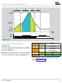
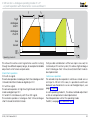
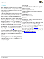
4.5.1 2-point operation
Operating mode 1
In idle state (DI 1 with no signal), the actuator is in “low” position
(“low” position may also be 0° = “closed” position).
If a signal is applied to digital input DI 1, the actuator moves
to “high” position in running time t1. As the signal at digital
input DI 1 drops, the actuator moves back to “low” position in
running time t2.
IC 20, IC 40 · Edition 04.14
DI 1
Off
On
Position
low/closed
high
If the signal at digital input DI 1 is deactivated before “high”
position is reached, the actuator moves directly to “low” position in the percentage time of t2.
The actuator operates in high/low (high/closed) intermittent
mode.
Possible parameter sets for this operating mode: P 68017,
P 68018 and P 68019, see page 54 (Parameter sets).
24
IC 40 function
t1
t2
t3
t4
high
middle
low
closed
t [s]
DI 1
t [s]
Operating mode 2
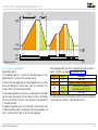
4.5.2 2-point operation with flame proving period
Operating mode 2
In idle state (DI 1 with no signal), the actuator is in “low” position
(“low” position may also be 0° = “closed” position).
If digital input DI 1 is activated, the actuator moves to “middle”
position in running time t1.
After the waiting time t2, the actuator automatically moves
further to “high” position in running time t3.
As the voltage at digital input DI 1 drops, the actuator closes
to the “low” position in running time t4.
IC 20, IC 40 · Edition 04.14
DI 1
Off
On
Position
low/closed
high
If the signal at digital input DI 1 is deactivated before “high”
position is reached, the actuator moves directly to “low” position in the percentage time of t4.
The actuator operates in high/middle/low (high/middle/
closed) intermittent mode.
On burners which must ignite during opening of the butterfly
valve, the waiting time t2 is appropriate for flame proving.
Possible parameter set for this operating mode: P 68021,
see page 54 (Parameter sets).
25
IC 40 function > Standard operating modes 1 – 12
t1
t2
t3
t1
t4
t2
high
middle
low
closed
t [s]
DI 1
DI 2
t [s]
Operating mode 3
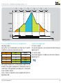
4.5.3 2-step operation with one or two digital inputs
Operating mode 3
In idle state (DI 1 and DI 2 with no signal), the actuator is in “low”
position (“low” position may also be 0° = “closed” position).
Control via two digital inputs
If digital input DI 2 is activated, the actuator moves from “low”
position to “middle” position in running time t1.
If, in addition, digital input DI 1 is activated, the actuator approaches “high” position in running time t2.
When the signal DI 1 drops, the actuator moves back to “middle” position in running time t3 and closes the control element
to the “low” position in running time t4 if the signal is also
disconnected from DI 2.
IC 20, IC 40 · Edition 04.14
The actuator operates in high/middle/low (high/middle/
closed) intermittent mode.
DI 1
Off
On
Off
On
DI 2
Off
Off
On
On
Position
low/closed
high (DI 1 has priority)
middle
high
In this operating mode, digital input DI 1 has priority and its
signal always leads to opening of the actuator to the “high”
position.
▼
26
IC 40 function > Standard operating modes 1 – 12 > 2-step operation with one or two digital inputs
t1
t2
high
middle
low
closed
t [s]
DI 1
DI 2
t [s]
Operating mode 3
This may prove to be practical in order, for instance, to purge
a furnace or kiln via DI 1 (independently of DI 2). It is then
possible to operate with both inputs in high/middle/low intermittent mode.
Possible parameter sets for this operating mode: P 68015,
P 68016, see page.54 (Parameter sets).
Control via one digital input
If digital input DI 1 is activated (DI 2 with no signal), the actuator moves to “high” position. The running times t1 and t2 run
directly in succession.
Likewise, the actuator closes in the successive running times
t3 and t4 if signal DI 1 drops. The “middle” position serves as
an interpolation point and can be freely programmed.
IC 20, IC 40 · Edition 04.14
Owing to the two successive running times, the opening characteristic of the butterfly valve can be changed. For example,
the characteristic of the air circuit can be adapted to that of
the gas circuit.
Running times up to 51 s (2 x 25.5 s) are possible in this operating mode. If the signal at digital input DI 1 is deactivated
before “high” position is reached, the actuator moves directly
to “low” position in the percentage times of t3 and t4.
The actuator operates in high/low (high/closed) intermittent
mode.
DI 1
Off
On
DI 2
Off
Off
Position
low/closed
high
27
IC 40 function > Standard operating modes 1 – 12
t1
t2
t3
t4
high
middle
low
closed
t [s]
DI 1
DI 2
t [s]
Operating mode 4
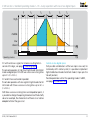
4.5.4 2-step operation with two digital inputs
Operating mode 4
The function corresponds to operating mode 3 with different
priority of the digital inputs.
Digital input DI 2 has priority over DI 1. This means that a signal
at DI 1 has no effect unless a signal is also applied to DI 2.
DI 1
Off
DI 2
Off
On
Off
Off
On
On
On
Position
low/closed
low/closed
(DI 2 has priority))
middle
high
Possible parameter set for this operating mode: P 68022,
see page 54 (Parameter sets).
IC 20, IC 40 · Edition 04.14
28
IC 40 function > Standard operating modes 1 – 12
t1
t2
high
low
closed
t [s]
DI 1
DI 2
t [s]
Operating mode 5
4.5.5 3-point step operation
Operating mode 5
If only digital input DI 1 is active, the actuator opens. If only
digital input DI 2 is active, the actuator closes.
If none of the two digital inputs or both digital inputs is or are
active simultaneously, the actuator stops in its position. This
means that it can stop at any position.
The actuator operates in continuous mode and is controlled
via a 3-point step signal. The actuating function is limited by
the “low” and “high” positions (“low” position may also be 0°
= “closed” position).
The opening speed is pre-set via the time t1 for the entire “low”
to “high” actuating travel. Accordingly, the closing speed is set
with t2 for the entire “high” to “low” actuating travel.
IC 20, IC 40 · Edition 04.14
Possible parameter sets for this operating mode: P 68012, P
68013, P 68014, see page 54 (Parameter sets).
DI 1
Off
On
DI 2
Off
Off
Off
On
On
On
Reaction
Idle/Stop
Open to “high” position at max.
Close to “low” position
(“closed” position) at min.
Idle/Stop
This method of control is frequently used on furnaces and kilns
in the sector of ceramics, steel and aluminium.
29
IC 40 function > Standard operating modes 1 – 12
t1
t2
t3
t4
t5
t6
high
middle
low
closed
t [s]
DI 1
DI 2
t [s]
Operating mode 6
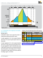
4.5.6 3-step operation with one or two digital inputs
Operating mode 6
Each of the 4 circuit combinations resulting from DI 1 and DI
2 determines precisely one actuator position:
DI 1
Off
On
Off
On
DI 2
Off
Off
On
On
Position
closed
low
middle
high
Control via one digital input
DI 2 with no signal:
The actuator operates in low/closed intermittent mode via
digital input DI 1.
DI 1 with no signal:
The actuator operates in middle/low intermittent mode via
digital input DI 2.
▼
Each signal change results in a new position setpoint for the
actuator. If the signals overlap (see t2), the actuator moves towards “high”. If the signals do not overlap (see t5), the actuator
moves towards “closed”.
Various modes of operation can be implemented with this
operating mode.
IC 20, IC 40 · Edition 04.14
30
IC 40 function > Standard operating modes 1 – 12 > 3-step operation with one or two digital inputs
t1
t2
t3
t4
t5
t6
high
middle
low
closed
t [s]
DI 1
DI 2
Operating mode 6
t [s]
DI 1 with continuous signal, for instance resulting from inControl via two digital inputs
version of the logic, see page 57 (Switching logic):
If all possible combinations of the two inputs are used, for
instance by a PLC control system, it is possible to implement
The actuator operates in high/low (high/closed) intermittent
high/middle/low/closed
intermittent mode (3 steps plus the
mode via digital input DI 2 with two successive running times
“closed”
position).
up to 51 s (2 x 25.5 s).
Possible parameter set for this operating mode: P 68001,
DI 1 and DI 2 are connected in parallel:
see
page 54 (Parameter sets).
The actuator operates with one signal in high/closed intermittent mode with three successive running times up to 76.5 s
(3 x 25.5 s).
With three successive running times via interpolation points, it
is possible to change the opening characteristic of the butterfly
valve. For example, the characteristic of the air circuit can be
adapted to that of the gas circuit.
IC 20, IC 40 · Edition 04.14
31
IC 40 function > Standard operating modes 1 – 12
t1
t2
high
middle
low
closed
t [s]
DI 1
DI 2
t [s]
Operating mode 7
4.5.7 2-point operation with switchover of the adjustment angle
for the “open” position
Operating mode 7
In idle state (DI 1 and DI 2 with no signal), the actuator is in “low”
position (“low” position may also be 0° = “closed” position).
Digital input DI 1 functions as a pulse input.
DI 2 has no signal:
The actuator operates in high/low (high/closed) intermittent
mode via digital input DI 1.
Signal at DI 2:
The actuator can switch over its intermittent mode between
high/low (high/closed) and middle/low (middle/closed) during ongoing operation. The adjustment angle for the “open”
position is then approached with signal at DI 1 and switched
over via DI 2.
IC 20, IC 40 · Edition 04.14
The actuator now operates in middle/low (middle/closed)
intermittent mode via digital input DI 1.
The heat output can now be reduced and it is nevertheless
possible to continue operation in intermittent mode so as to
ensure a uniform temperature distribution. High/low may
also be used for purging and middle/low may also be used
for heating mode in order, for instance, to reduce the prepurge time.
DI 1
Off
On
DI 2
Off
Off
Off
On
On
On
Position
low/closed
high
low/closed
(DI 1 has priority)
middle
▼
32
IC 40 function > Standard operating modes 1 – 12
t1
t2
high
middle
low
closed
t [s]
DI 1
DI 2
t [s]
Operating mode 7
The opening speed is pre-set via the running time t 1 for the
entire “low” to “high” actuating travel. Accordingly, the closing speed is set with t2 for the entire “high” to “low” actuating
travel. The speeds are retained when switching with reduced
capacity (signal at DI 2). The running time is shortened in accordance with the reduced position.
Alternative function (2-step operation with constant speed):
DI 1
Off
On
DI 2
Off
Off
Off
On
On
On
IC 20, IC 40 · Edition 04.14
Position
low/closed
high
low/closed
(DI 1 has priority)
middle
For as long as a signal is applied to DI 1, DI 2 switches to and
fro between “high” and “middle” position. In this case, it may
be practical to invert the logic of digital input DI 2, see page
57 (Switching logic).
This mode of operation ensures that the actuator always opens
or closes at constant speed.
Possible parameter set for this operating mode: P 68023,
see page 54 (Parameter sets).
33
IC 40 function > Standard operating modes 1 – 12
t1
t2
high
middle
low
closed
t [s]
DI 1
DI 2
t [s]
Operating mode 8
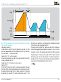
4.5.8 2-point operation with input-dependent adjustment angle
for the “open” position
Operating mode 8
The function corresponds to operating mode 7 apart from the
fact that both digital inputs function as pulse inputs.
The actuator operates in high/low (high/closed) intermittent
mode via digital input DI 1 and operates in middle/low (middle/closed) mode via DI 2.
A signal at DI 1 (priority) always leads to approaching to “high”
position which, for instance, can be used to purge the furnace
or kiln.
IC 20, IC 40 · Edition 04.14
DI 1
Off
On
Off
On
DI 2
Off
Off
On
On
Position
low/closed
high
middle
high (DI 1 has priority)
Alternative function: 2-step operation with constant speed.
For as long as a signal is applied to DI 2, DI 1 switches to and
fro between “high” and “middle” position.
This mode of operation ensures that the actuator always opens
or closes at constant speed.
Possible parameter set for this operating mode: P 6802,
see page 54 (Parameter sets).
34
IC 40 function > Standard operating modes 1 – 12
t1
t2
t3
t4
high
low
closed
t [s]
DI 1
DI 2
t [s]
Operating mode 9
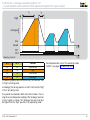
4.5.9 2-point operation with switchover of the running times
Operating mode 9
Digital input DI 1 functions as a pulse input.
The actuator operates in high/low (high/closed) intermittent
mode via digital input DI 1.
In idle state (DI 1 with no signal), the actuator is in “low” position
(“low” position may also be 0° = “closed” position).
DI 1
Position
Off
low/closed
On
high
IC 20, IC 40 · Edition 04.14
The running times are switched over via DI 2.
DI 2
Off
On
Opening time
t1
t3
Closing time
t2
t4
Switchover of the running times may also occur during movement of the actuator.
This function can also, for instance, be used for fast movement
to the pre-purge position, with correspondingly slow running
time for burner operation.
Possible parameter set for this operating mode: P 68025,
see page 54 (Parameter sets).
35
IC 40 function > Standard operating modes 1 – 12
t1
t2
t3
t4
high
middle
{
low
closed
t [s]
DI 1
DI 2
t [s]
Operating mode 10
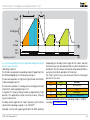
4.5.10 3-point step operation with running time fractions
Operating mode 10
If only digital input DI 1 is active, the actuator opens. If only
digital input DI 2 is active, the actuator closes.
If none of the two digital inputs or both digital inputs is or are
active simultaneously, the actuator stops in its position. The
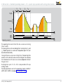
actuator can be stopped in any position.
The actuator operates in continuous mode and is controlled
via a 3-point step signal.
The actuating function is limited by the “low” and “high” positions (“low” position may also be 0° = “closed” position).
IC 20, IC 40 · Edition 04.14
DI 1
Off
ON
DI 2
Off
Off
Off
ON
ON
ON
Reaction
Idle/Stop
Open to “high” position at max.
Close to “low” position
(“closed” position) at min.
Idle/Stop
▼
36
IC 40 function > Standard operating modes 1 – 12 > 3-point step operation with running time fractions
t1
t2
t3
t4
high
middle
{
low
closed
t [s]
DI 1
DI 2
Operating mode 10
t [s]
The opening time results from the two successive running
times t1 and t2.
The closing time results accordingly from running times t3 and
t4. “Middle” position is used as an interpolation point. This can
be defined individually.
Owing to the two successive running times, the opening characteristic of the butterfly valve can be changed. For example,
the characteristic of the air circuit can be adapted to that of
the gas circuit.
Running times up to 51 s (2 x 25.5 s) are possible in this operating mode.
Possible parameter sets for this operating mode: P 68010, P
68011 and P 68020, see page 54 (Parameter sets).
IC 20, IC 40 · Edition 04.14
37
IC 40 function > Standard operating modes 1 – 12
t1
t2
t3
t4
t5
t6
high
middle
low
closed
t [s]
DI 1
DI 2
t [s]
Operating mode 11
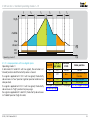
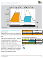
4.5.11 3-step operation with two digital inputs
Operating mode 11
In idle state (DI 1 and DI 2 with no signal), the actuator is in
“closed” position and the butterfly valve is closed.
If a signal is applied to DI 1 (DI 2 with no signal), the butterfly
valve moves to “low” position (ignition position and low-fire
rate position).
If a signal is applied to DI 2 (DI 1 with no signal), the butterfly
valve moves to “high” position for pre-purge.
If a signal is applied to DI 1 and DI 2, the butterfly valve moves
to “middle” position (high-fire rate).
IC 20, IC 40 · Edition 04.14
DI 1/V1
Off
DI 2/
air valve
Off
Position
IC 40
closed
Valve position
Closed
Igniting position/lowOn
Off
low
fire rate
On
On
middle
High-fire rate
Off
On
high
Pre-purge
Example of application, see page 11 (IC 40, staged control
with pre-purge)
38
IC 40 function > Standard operating modes 1 – 12
t1
t1
t2
high
middle
low
closed
t [s]
DI 1
DI 2
t [s]
Operating mode 12
4.5.12 3-point step operation with low position
Operating mode 12
If a three-point step signal is applied to DI 1 (DI 2 with no signal),
the butterfly valve moves to “high” position.
If a three-point step signal is applied to DI 2 (DI 1 with no signal),
the butterfly valve moves to “middle” position.
If no three-point step signal is applied to the inputs (DI 1 and
DI 2 with no signal), the actuator stops and the butterfly valve
remains in its current position.
If a three-point step signal is applied to inputs DI 1 and DI 2, the
actuator moves from the low-fire rate position to “low” position.
IC 20, IC 40 · Edition 04.14
DI 1 DI 2
Off Off
IC 40 position
Idle/Stop
On
Off
Open to high position
Off
On
Close to middle position
On
On
low
Valve position
Idle
Open to high-fire
rate
Close to low-fire
rate
Valve closes further
Example of application, see page 10 (IC 40, continuous
control by three-point step signal)
39
IC 40 function
t1
t2
high
analogue
low
closed
t [s]
DI 1
t [s]
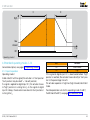
Operating mode 21
4.6 Analogue operating modes 21 – 27
General description, see page 22 (Operating modes).
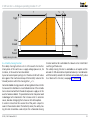
4.6.1 2-point operation
Operating mode 21
In idle state (DI 1 with no signal), the actuator is in “low” position
(“low” position may also be 0° = “closed” position).
If a signal is applied to digital input DI 1, the actuator moves to
the position pre-set via analogue input 4 – 20 mA. When the
signal at DI 1 drops, the actuator moves back to “low” position.
The actuator operates in circuit intermittent mode analogue/
low (analogue/closed), whereby the analogue signal determines the adjustment angle for the “open” position (= setpoint).
The adjustment angle for the “open” position which can be
varied via the analogue signal is set in BCSoft®.
IC 20, IC 40 · Edition 04.14
Example: 4 mA for 60% opening and 20 mA for 100% opening.
If no analogue value is pre-set, the actuator remains in “low”
position (“closed” position).
DI 1
Off
On
Position
low/closed
analogue
The opening speed is pre-set via the time t1 for the entire “low”
to “high” actuating travel. Accordingly, the closing speed is set
with t2 for the entire “high” to “low” actuating travel.
▼
40
IC 40 function > Analogue operating modes 21 – 27 > 2-point operation
T
t2
t1
analogue
high
low
closed
t [s]
DI 1
t [s]
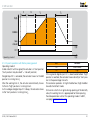
Operating mode 21 with prolonged reaction time
The “high” position can be selected correspondingly lower in
order to obtain longer running times (> 25.5 s).
The “high” position does not limit the adjustment angle for the
“open” position but defines only the speeds here.
Consequently, the “high” position may also be lower than the
“analogue” position. The magnitude of the current signal is
crucial as regards the “analogue” position.
Example for double running time T:
The “high” position is set to 50%.
T = t1
100%
high
T = 25.5 s
100%
50%
T = 51 s
Possible parameter set for this operating mode:
P 68026, see page 54 (Parameter sets).
Note:
The running time can be prolonged up to max. 150 s for the
full adjustment range 0 – 90°. Running times outside of this
permitted range are adapted automatically by BCSoft®.
IC 20, IC 40 · Edition 04.14
41
IC 40 function > Analogue operating modes 21 – 27
t1
t2
high
analogue
{
low
closed
t [s]
DI 1
DI 2
t [s]
Operating mode 22
4.6.2 2-point operation with switchover of the adjustment angle
for the “open” position
Operating mode 22
In idle state (DI 1 and DI 2 with no signal), the actuator is in “low”
position independently of the analogue signal (“low” position
may also be 0° = “closed” position).
Signal at DI 1, DI 2 with no signal:
The actuator operates in high/low (high/closed) intermittent
mode via digital input DI 1.
Digital input DI 1 functions as a pulse input.
Signal at DI 2:
Intermittent mode can switch in ongoing operation between
high/low (high/closed) and analogue/low (analogue/closed).
The adjustment angle for the “open” position is then approached with signal at DI 1 and switched over via DI 2. The
IC 20, IC 40 · Edition 04.14
actuator now operates in analogue/low (analogue/closed)
intermittent mode via digital input DI 1.
The adjustment angle for the “open” position which can be varied via the analogue signal (position setpoint) is set in BCSoft ®.
Example: 4 mA for 60% opening and 20 mA for 100% opening.
Depending on the adjustment angle for the “open” position,
the heat output can be reduced and a uniform temperature
distribution in the furnace or kiln can be achieved nevertheless
owing to intermittent operation of the burner.
▼
42
IC 40 function > Analogue operating modes 21 – 27
> 2-point operation with switchover of the adjustment angle for the “open” position
t1
t2
high
analogue
{
low
closed
t [s]
DI 1
DI 2
t [s]
Operating mode 22
DI 1
Off
On
Off
On
DI 2
Off
Off
On
On
Position
low/closed
high
low/closed
analogue
Possible parameter set for this operating mode:
P 68027, see page 54 (Parameter sets).
The opening speed is pre-set via the time t1 for the entire “low”
to “high” actuating travel.
Accordingly, the closing speed is set with t2 for the entire “high”
to “low” actuating travel.
The speeds are retained in both intermittent modes. The running times are changed accordingly if the “analogue” position
(current signal) is moved. The “analogue” position may also
be higher than the “high” position in this operating mode.
IC 20, IC 40 · Edition 04.14
43
IC 40 function > Analogue operating modes 21 – 27
t1
t2
high
analogue
{
low
closed
t [s]
DI 1
DI 2
t [s]
Operating mode 23
4.6.3 2-point operation with input-dependent adjustment angle
for the “open” position
Operating mode 23
The function corresponds to operating mode 22 apart from the
fact that both digital inputs function as pulse inputs.
The actuator operates in high/low (high/closed) intermittent
mode via digital input DI 1.
The actuator operates in analogue/low (analogue/closed)
intermittent mode via digital input DI 2.
A signal at DI 1 (priority) always leads to approaching “high”
position. This application can be used, for instance, for purging a furnace or kiln.
The adjustment angle for the “open” position which can be
varied via the analogue signal is set in BCSoft®.
Example: 4 mA for 60% opening and 20 mA for 100% opening.
IC 20, IC 40 · Edition 04.14
Depending on the adjustment angle for the “open” position,
the heat output can be reduced and a uniform temperature
distribution in the furnace or kiln can be achieved nevertheless
owing to intermittent operation of the burner.
The “high” position may also be lower than the “analogue”
position in this case.
DI 1
Off
On
Off
On
DI 2
Off
Off
On
On
Position
low/closed
high
analogue
high (DI 1 has priority)
Possible parameter set for this operating mode: P 68028,
see page 54 (Parameter sets).
44
IC 40 function > Analogue operating modes 21 – 27
t1
t2
t3
t4
high
analogue
{
low
closed
t [s]
DI 1
DI 2
t [s]
Operating mode 24
4.6.4 2-point operation with switchover of the running times
Operating mode 24
Digital input DI 1 functions as a pulse input. The actuator operates in analogue/low (analogue/closed) intermittent mode
via DI 1.
In idle state (DI 1 with no signal), the actuator is in “low” position.
(“low” position may also be 0° = “closed” position).
The adjustment angle for the “open” position which can be
varied via the analogue signal is set in BCSoft®.
Example: 4 mA for 60% opening and 20 mA for 100% opening.
Depending on adjustment angle for the “open” position, the
heat output can be reduced and a uniform temperature distribution in the furnace or kiln can be achieved nevertheless
owing to intermittent operation of the burner.
IC 20, IC 40 · Edition 04.14
DI 1
Off
On
Position
low/closed
analogue
The running times are switched over via DI 2.
DI 2
Off
On
Opening time
t1
t3
Closing time
t2
t4
The running times can also be switched over in ongoing operation.
▼
45
IC 40 function > Analogue operating modes 21 – 27
> 2-point operation with switchover of the running times
t1
t2
t3
t4
high
analogue
{
low
closed
t [s]
DI 1
DI 2
Operating mode 24
t [s]
The “high” position can be selected correspondingly lower in
order to obtain longer running times (> 25.5 s).
The “high” position does not limit the adjustment angle for the
“open” position but only defines the speeds.
Consequently, the “high” position may also be lower than the
“analogue” position. The magnitude of the current signal is
crucial as regards the “analogue” position.
Possible parameter set for this operating mode:
P 68029, see page 54 (Parameter sets).
IC 20, IC 40 · Edition 04.14
46
IC 40 function > Analogue operating modes 21 – 27
t1
t2
high
analogue
chart 1
analogue
chart 2
low
closed
t [s]
DI 1
DI 2
t [s]
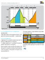
Operating mode 25
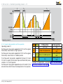
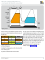
4.6.5 2-point operation with characteristic curve switchover I
Operating mode 25
In idle state (DI 1 and DI 2 with no signal), the actuator is in “low”
position (“low” position may also be 0° = “closed” position).
DI 1 functions as a pulse input. The analogue characteristic
curve (analogue chart 1/analogue chart 2) is switched over
via DI 2 and the adjustment angle for the “open” position is
pre-set by this. This angle is approached with signal at DI 1.
DI 2 with no signal:
The actuator operates in analogue chart 1/low (analogue
chart 1/closed) intermittent mode via digital input DI 1.
Signal at DI 2:
The actuator operates in analogue chart 2/low (analogue
chart 2/closed) intermittent mode via digital input DI 1.
This function allows the actuator to switch over its intermittent
mode in ongoing operation. The adjustment angle for the “open”
position is pre-set via two characteristic curves (charts), each
with 5 interpolation points, see page 57 (Inputs). This allows
the same current signal to be used for running through two different capacity ranges, for example for lambda adjustment or
for hot-air compensation.
The adjustment angles for the “open” position of the characteristic curves chart 1 and chart 2 can be set mutually independently. The adjustment angle for the “open” position of chart 2
may thus also be higher than that of chart 1.
▼
IC 20, IC 40 · Edition 04.14
47
IC 40 function > Analogue operating modes 21 – 27
> 2-point operation with characteristic curve switchover I
t1
t2
high
analogue
chart 1
analogue
chart 2
low
closed
t [s]
DI 1
DI 2
Operating mode 25
t [s]
The burner continues to be operated in intermittent mode so
as to ensure a uniform temperature distribution even with
low heat output.
The “high” position can be selected correspondingly lower
in order to obtain longer running times (> 25.5 s). The “high”
position does not limit the adjustment angle for the “open”
position but only defines the speeds. The adjustment angles
DI 1
DI 2
Position
for the “open” position are pre-set by the current signal.
Off
Off
low/closed
Consequently, “high” position may also be lower than the
On
Off
analogue chart 1
“analogue
chart” positions. If no analogue value is pre-set, the
low/closed
Off
On
actuator remains in “low” position (“closed” position).
On
On
analogue chart 2
Possible parameter set for this operating mode:
The opening speed is pre-set via the time t1 for the entire “low”
P 68030, see page 54 (Parameter sets).
to “high” actuating travel.
Accordingly, the closing speed is set with t2 for the entire “high”
to “low” actuating travel.
The speeds are retained in both intermittent modes.
IC 20, IC 40 · Edition 04.14
48
IC 40 function > Analogue operating modes 21 – 27
t1
t2
high
analogue
chart 1
analogue
chart 2
low
closed
t [s]
DI 1
DI 2
t [s]
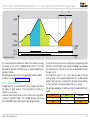
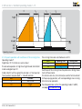
Operating mode 26
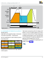
4.6.6 2-point operation with characteristic curve switchover II
Operating mode 26
In idle state (DI 1 with no signal), the actuator is in “low” position
(“low” position may also be 0° = “closed” position).
Each circuit combination of DI 1 and DI 2 determines precisely
one actuator position:
DI 1
Off
ON
Off
ON
DI 2
Off
Off
ON
ON
Position
low/closed
analogue chart 1
high
analogue chart 2
“High” position may also be lower than the “analogue chart”
positions in this case. The opening speed is pre-set via the
running time t1 for the entire “low” to “high” actuating travel.
Accordingly, the closing speed is set with t2 for the entire “high”
to “low” actuating travel. The speeds are independent of the
digital inputs and the analogue input in this case.
Two characteristic curves, each with 5 interpolation points, are
available, see page 57 (Inputs).
▼
A change in the circuit combination directly triggers approach
to the new position.
IC 20, IC 40 · Edition 04.14
49
IC 40 function > Analogue operating modes 21 – 27
> 2-point operation with characteristic curve switchover II
t1
t2
high
analogue
chart 1
analogue
chart 2
low
closed
t [s]
DI 1
DI 2
Operating mode 26
This allows the same current signal to be used for running
through two different capacity ranges, for example for lambda
adjustment or for hot-air compensation.
Intermittent operation
DI 2 with no signal:
The actuator operates in analogue chart 1/low (analogue chart
1/closed) intermittent mode via digital input DI 1.
DI 1 with no signal:
The actuator operates in high/low (high/closed) intermittent
mode via digital input DI 2.
DI 1 and DI 2 simultaneously with ON or OFF signal:
The actuator operates in analogue chart 2/low (analogue
chart 2/closed) intermittent mode.
IC 20, IC 40 · Edition 04.14
t [s]
If all possible combinations of the two inputs are used, for
instance by a PLC control system, this allows high/analogue
chart 1/analogue chart 2/low (closed) intermittent mode to
be implemented.
Continuous operation
The actuator may also operate in continuous mode via current input 4 – 20 mA. In this case, it is possible to switch over
between two characteristic curves via the digital inputs, see
page 57 (Inputs).
As with operating mode 25, this allows lambda adjustment
or hot-air compensation to be implemented.
Possible parameter set for this operating mode:
P 68031, see page 54 (Parameter sets).
50
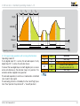
IC 40 function > Analogue operating modes 21 – 27
t1
t2
t3
t4
t5
t6
high
analogue
input AI
low
closed
t [s]
DI 1
DI 2
t [s]
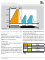
Operating mode 27
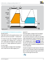
4.6.7 2-step operation with two digital inputs and variable
adjustment angle
Operating mode 27
In idle state (DI 1 and DI 2 with no signal), the actuator is in
“closed” position and the butterfly valve is closed.
If a signal is applied to DI 1 (DI 2 with no signal), the butterfly
valve moves to “low” position (ignition position and low-fire
rate position).
If a signal is applied to DI 2 (DI 1 with no signal), the butterfly
valve moves to “high” position for pre-purge (high-fire rate).
If a signal is applied to DI 1 and DI 2, the butterfly valve can be
moved steplessly between the low-fire rate position and the
high-fire rate position via the analogue input AI. The adjustment angle for the “open” position which can be varied via
the analogue signal is set in BCSoft®.
IC 20, IC 40 · Edition 04.14
Example: 4 mA for 60% opening and 20 mA for 100% opening.
DI 1 DI 2 IC 40 position
Off
On
Off
Off
closed
low
On
On
AI
Off
On
high
Valve position
Closed
Ignition position/low-fire rate
Any position between ignition
position and pre-purge
Pre-purge/high-fire rate
Example of application, see page 12 (IC 40, continuous
control with defined ignition position)
51
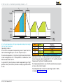
IC 40 function > Analogue operating modes 21 – 27
t1
t2
tS
high
low
closed
t [s]
DI 1
Power
Safety closing function
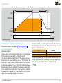
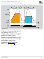
4.6.8 Safety closing function
The safety closing function cuts in in the event of a fault or
interruption of the continuous supply voltage (power) or, for
instance, in the event of a motor defect.
A pre-tensioned spiral spring turns the drive shaft with valve
disc against the mechanical stop of the butterfly valve to the
“closed” position within the closing time tS < 1 s.
Fast and reliable closing prevents air being able to flow into the
furnace or kiln chamber in uncontrolled manner if the installation is disconnected from the electrical power supply or in the
event of a device defect. The penetration of air may also lead
to damage to the material in the furnace or kiln in extreme
cases, besides changing the furnace or kiln atmosphere.
In order to maximize the service life of the parts subject to
wear in the actuator and in the butterfly valve, the safety closing function should be used only for the scheduled closing
IC 20, IC 40 · Edition 04.14
t [s]
function and not for controlled shut-down or for intermittent
switching of the burner.
The safety closing function is available as an option on the
actuator IC 40S and can be implemented only in combination
with the butterfly valve BVHS. Both actuator and butterfly valve
must feature this function, see page 69 (Selection).
52
IC 40 function
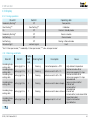
4.7 Parameters
Various parameter sets are saved in the BCSoft® software to
assist programming. Selecting a parameter set pre-selects the
corresponding operating mode and assigns practical values
to all parameters which can be set. Each parameter can be
tailored to the individual requirements of the installation
IC 20, IC 40 · Edition 04.14
53
IC 40 function > Parameters
4.7.1 Parameter sets
Parameter set
Operating mode Function
P68001
6
3-step operation with one or two digital inputs, running time: 6 s
P68010
10
3-point step operation with running time fractions, running time: 51 s
P68011
10
3-point step operation with running time fractions, running time: 30 s
P68012
5
3-point step operation, running time: 15 s
P68013
5
3-point step operation, running time: 7.5 s
P68014
5
3-point step operation, running time: 4.5 s
P68015
3
2-step operation with one or two digital inputs, running time: 51 s
P68016
3
2-step operation with one or two digital inputs, running time: 30 s
P68017
1
2-point operation, running time: 15 s
P68018
1
2-point operation, running time: 7.5 s
P68019
1
2-point operation, running time: 4.5 s
P68020
10
3-point step operation with running time fractions, running time: 15 s
P68021
2
2-point operation with flame proving period, running time: 4.5 s
P68022
4
P68023
7
P68024
8
2-step operation with two digital inputs, running time: 5 s
2-point operation with switchover of the adjustment angle for the “open” position,
running time: 4.5 s
2-point operation with input-dependent adjustment angle for the “open” position,
running time: 4.5 s
▼
IC 20, IC 40 · Edition 04.14
54
IC 40 function > Parameters > Parameter sets
Parameter set
P68025
P68026
P68027
P68028
P68029
P68030
P68031
Operating mode Function
9
2-point operation with switchover of the running times, running time: 4.5 s/15 s
21
2-point operation, running time: 7.5 s
2-point operation with switchover of the adjustment angle for the “open” position,
22
running time: 7.5 s
2-point operation with input-dependent adjustment angle for the “open” position,
23
running time: 7.5 s
24
2-point operation with switchover of the running times, running time: 4.5 s/ 15 s
25
2-point operation with characteristic curve switchover I, running time: 7.5 s
26
2-point operation with characteristic curve switchover II, running time: 7.5 s
IC 20, IC 40 · Edition 04.14
55
IC 40 function > Parameters
4.7.2 Factory default parameters
Factory default parameters are data saved permanently in
the unit and which can be viewed in BCSoft®. This includes
motor data and calibration data.
In addition, information on which parameter set was entered
in the condition as delivered is also saved in the factory default
parameters, see page 54 (Parameter sets).
Certain special functions can be programmed with this, changing the behaviour of the digital inputs, see page 57 (Switching logic).
IC 20, IC 40 · Edition 04.14
56
IC 40 function
4.8 Inputs
4.8.1 Digital
In the basic setting, the two digital inputs operate as universal
inputs. If a voltage of 24 V DC or 100 – 230 V AC is applied
to the input, this is recognized as “On” signal (positive logic).
Switching logic
The switching logic can be inverted for each individual digital
input. An applied voltage is then recognized as “Off” signal
while no voltage results in an “On” signal (negative logic).
Inversion of the input switching logic in conjunction with the
operating modes provides new options for defining the behaviour of the actuator.
4.8.2 Analogue
The actuator can approach corresponding intermediate positions via a current signal to the additional input. This function
can be used only if an actuator IC 40 with 4 – 20 mA analogue input is connected (option). The switch-on and switch-off
threshold of the analogue input is defined at approx. 3 mA.
The assignment of current value to position can be freely defined via 5 pairs of values (interpolation points).
One position which the actuator approaches when the corresponding current signal is applied can be assigned to each of
the interpolation points at 4, 8, 12, 16 and 20 mA. The position
is interpolated on the basis of a linear function in each case
between the interpolation points.
In the case of operating modes 25 and 26, 2 characteristic
curves, each with 5 interpolation points, can be defined. In
this case, the digital inputs define which characteristic curve
currently applies. This allows the same current signal to be
used to run through two different capacity ranges, for example
for lambda adjustment or for hot-air compensation, see page
47 (2-point operation with characteristic curve switchover
IC 20, IC 40 · Edition 04.14
I) and see page 49 (2-point operation with characteristic
curve switchover II).
Filtering and hysteresis of the current signal
In order to suppress noise of the current signal, the analogue
input is sampled equidistantly every millisecond and a mean
value is generated over 0.1 s. This filtering can be prolonged up
to 1 s in the case of a very poor input signal. However, this also
prolongs the response time to a change at the analogue input.
The current input (4 – 20 mA) operates internally with a resolution of 10 bit (corresponding to 0.1% of the actuator). This allows
the analogue input to detect a change of 0.02 mA (hysteresis).
If the input signal fluctuates too greatly (owing to noise for
instance), this high resolution results in constant corrections
of the actuator and butterfly valve (when mounted onto BVA,
BVAF, BVG, BVGF, BVH or BVHS).
Consequently, the hysteresis may be increased to up to 0.2 mA.
The resolution in this case is reduced down to 1% of the actuator
accordingly. The maximum resolution is always set in each
case as the basic setting.
▼
57
IC 40 function > Inputs > Analogue
Priority and running time in operating modes 1 – 10
In operating modes 1 to 10, the actuator is positioned (0 – 100%)
by both digital inputs DI 1 and DI 2. Alternatively, on the
IC 40A..A, there is the option of positioning the actuator with
a 4 – 20 mA current signal. Simultaneous presets via the analogue input and via the digital inputs necessitate defining a
priority in BCSoft®. The digital inputs have priority by default.
Opening speeds and closing speeds between 0 and 25.5 s
can be set for analogue mode. The time always relates to the
distance between the positions at 4 and 20 mA. If the current
signal changes more slowly than the set running time, the
actuator follows more slowly accordingly through to step-bystep movement, see page 23 (Running times).
IC 20, IC 40 · Edition 04.14
58
IC 40 function
4.9 Outputs
Device defective:
An
internal fault, such as a fault in the memory chip, leads
Various, independent signalling functions can be assigned to
to
failure
of the device.
the two outputs RO 1 and RO 2: closed position, low position,
Internal
warning
(reference switch):
middle position and high position, fault signals and freely
Internal
monitoring
of the motor position has detected a
programmable positions.
fault. Recalibrate!
2 relays with change-over contacts are available for signalling. The contacts are floating and are thus referred to as dry Internal temperature > 90°C:
Warning! Attach heat deflectors.
contacts. They can be integrated in automation processes.
Service note:
For instance, reaching the pre-set position can be signalled
Number of cycles, changes of direction or relay switching
back as a signal function. The range in which the output
operations
greater than limit.
switches can be defined in BCSoft® using the relational op“Fault
signals”
also covers a “Device in Manual mode” signal
erator. The range may be =, ≥ or ≤ of the set position. Thus,
even
though
the
signal is not actually a fault signal.
for instance, the behaviour of a cam disk can be simulated.
®
Example for output 1 (RO 1): if the condition is met, the output The precise cause of the signal is displayed in BCSoft and
saved
in
the
statistics,
see
page
61
(Statistics).
relay is energized. Terminals 10 and 12 are connected, see
The feedback signal of the IC 40 may not be used on its own
page 62 (IC 40 connection diagram).
The switching range can also be set individually via one min- for fail-safe signalling of a status or a fail-safe position, see
imum value and one maximum value. These settings are page 70 (Project planning information).
independent of the selected low position, middle position or
high position.
A feedback signal can also be used as a fault signal. In BCSoft®,
it is possible to select what status is to lead to setting of the
output (relay energized).
IC 20, IC 40 · Edition 04.14
59
IC 40 function
4.10 Manual mode
For simplified commissioning, the actuator can be operated
“by hand” via the BCSoft® software. Manual mode is activated
via BCSoft®.
A distinction is made between two types of Manual-mode:
Direct position preset and Simulate inputs. The related setting options are enabled after the required Manual mode is
selected.
The exterior, applied input signals have no effect on the control
element in both Manual operating modes. Instead, the device
responds to the presets from the software.
Fast blinking of the blue LED indicates that the actuator is in
Manual mode.
Only one Manual mode may be activated at any one time. If
the Manual mode is to be changed, the existing Manual mode
must first be deactivated before the other Manual mode can
be activated.
4.10.2 Simulate inputs
When this Manual mode is activated, the external inputs are
deactivated. Instead, the signals of the two digital inputs can
be pre-set “manually”. If the actuator has a 4 – 20 mA analogue
input (option), this can also be simulated.
Switching the inputs allows the behaviour of the actuator to
be tested. This allows the set running times to be checked
and optimized in BCSoft®.
4.10.1 Direct position preset
This Manual mode serves to determine the operating positions
for the process, such as the low-fire rate (low) position, the
ignition (middle position) and the high-fire rate (high) position.
For this purpose, the actuator can be moved to any position,
regardless of the input signal. The position can be entered
or changed directly in BCSoft®. The resolution is defined in
ranges fine/medium/coarse, whereby “fine” allows any step
of the step motor (< 0.05%).
After transfer of the values from BCSoft® to the actuator, the
actuator responds accordingly to the new presets. The new
position is always approached at maximum speed in this case.
The operating position determined can be assigned in BCSoft®
to a position, for example ignition position.
IC 20, IC 40 · Edition 04.14
60
IC 40 function
4.11 Statistics
The statistical data stored in the unit, such as fault signals
which have occurred, various counter readings and measured
values, is displayed in statistics in BCSoft®.
The counters and measured values ranges are each split into
overall data and customer data. The customer data is used
for recording information over a specific period.
4.11.1 Counters
Actuating cycles (0 – 100 – 0%), changes of direction (Open/
Closed), switching of the output relays, “Power On” switching
operations and mains operating hours are added in the statistics. Besides the total counters, there are customer counters
for recording information over a specific period.
4.11.3 Resetting statistics
All signals and customer data can be reset. The reset date
is saved automatically and displayed together with the customer data.
Counters and measured values cannot be reset or deleted.
4.11.4 Resetting a signal
A fault signal is signalled by the red LED on the actuator. The
detailed cause of the signal is displayed in BCSoft®. The cause
must be remedied. The signal can then be acknowledged
and reset with BCSoft®.
4.11.2 Measured values
The minimum and maximum internal housing temperatures
are saved in statistics. In addition, the current internal temperature is displayed. Here as well, there is a customer memory
for viewing a period.
IC 20, IC 40 · Edition 04.14
61
IC 40 function
PE
R..
4.12 IC 40 connection diagram
M
See page 70 (Project planning information).
See page 76 (Technical data).
IC 40
DC
AC
1
D
2
4 5
7
N L1
+ –
+ –
Power
100 – 230 VAC
50 – 60 Hz
IC 20, IC 40 · Edition 04.14
8
DI 1 / DI 2
100 – 230 VAC
24 VDC
10 11 12
14 15 16
RO 1 / RO 2
max. 230 VAC
max. 2 A
A
18 19
+ –
AI
20 21 22
Potentiometer
4 – 20 mA max. 0.25 W
62
IC 40 function
4.13 Display
4.13.1 During operation
Blue LED
Red LED
Operating state
Off
Zero position
Moderately flashing**
Slow flashing***
Calibration
On
Slow flashing***
Off
Device in Standby mode
Moderately flashing**
Off
Device in motion
Fast flashing
Off
Manual mode
Fast flashing
Off
Moving in Manual mode
see Fault signal
Fault
Permanent light
* Fast: 5 times per second, ** moderately: 3 times per second, *** slow: once per second
4.13.2 Warnings and faults
Blue LED
Red LED
BCSoft®
fault
code
Warning/fault
According to opFlashing light (1×)
erating state
According to opFlashing light (2×)
erating state
According to opFlashing light (3×)
erating state
1
Warning
4
Warning
7
Warning
According to opFlashing light (4×)
erating state
8
Warning
According to opFlashing light (5×)
erating state
9
Warning
According to opFlashing light (6×)
erating state
10
Warning
Description
Internal temperature > 90°C
Cause
- High ambient temperature
- Mechanical valve offset
- Valve moving against its stop
- Mechanical valve offset
Reference switch drift > 10%
- Valve moving against its stop
- Valve blocked
- Large mechanical offset
Reference switch does not open
- Internal fault
- Actuator offset
- Valve blocked
Reference switch does not close - Internal fault
- Actuator offset, mechanical offset
- Signal interrupted
Analogue input AI < 4 mA
- Signal not connected
- Input defective
Reference switch drift > 5%
▼
IC 20, IC 40 · Edition 04.14
63
IC 40 function > Display > Warnings and faults
BCSoft
fault
code
Warning/fault
21
Warning
22
Warning
According to oper- Flashing
ating state
light (9×)
23
Warning
Flashing light (1×)
Permanent light
5
Fault
Flashing light (2×)
Permanent light
11
Fault
Flashing light (3×)
Permanent light
12
Fault
Flashing light (4×)
Permanent light
13
Fault
14
Fault
30
Fault
31
Fault
32
Fault
Saving error: user calibration
33
Fault
Saving error: analogue parameters
Blue LED
Red LED
According to oper- Flashing
ating state
light (7×)
According to oper- Flashing
ating state
light (8×)
Flashing light (5×)
Flashing light (6×)
Flashing light (7×)
Flashing light (8×)
Flashing light (9×)
Permanent light
Permanent light
Permanent light
Permanent light
Permanent light
IC 20, IC 40 · Edition 04.14
Description
Cause
Service note: number of OPEN/CLOSE
cycles > limit value
Service note: number of changes of
direction > limit value
Service note: number of relay output
RO 1 or RO 2 switching operations >
limit value
Internal fault
- e.g. EEPROM reading or writing error
- Valve blocked
Zero position: reference switch does - Internal fault
not close
- Actuator offset
- Valve not closed (BVHS)
- Valve blocked
Zero position: reference switch does
- Internal fault
not open
- Actuator offset
- Spring defective/not strong enough
Zero position: reference switch opens
- Valve not closed tightly
too early (BVHS)
- Cam maladjusted
Zero position: reference switch opens - Motor or gear defective
too late (BVHS)
- Cam maladjusted
Saving error for adjustable parameters, etc.
Saving error: factory default parameters
64
IC 40 function
4.14 Relay outputs RO 1 and RO 2 function
The function of digital outputs RO 1 and RO 2 can be adjusted using BCSoft®.
Signal at RO 1 or RO 2
Further setting options
CLOSED position
equal to =
Low-fire rate position (low)
greater than or equal to > =
Intermediate position (middle)
equal to or less than < =
OPEN position (high)
Remarks
Freely programmable position
Minimum and maximum value [°, %]
Relay switches when valve between min.
and max. position
Faults and warnings
Reference switch drift > 5%*
Reference switch drift > 10%*
Reference switch does not open*
Reference switch does not close*
Internal temperature > 90°C
Analogue input AI < 4 mA
Service note
Faults are always signalled, warnings are
signalled depending on the selection in
BCSoft® (see Inputs/Outputs, Display of
warnings)
Fault
Manual mode
Ready
None
Only faults are displayed
Device is in Manual mode
Relay drops out in the event of: faults (not
in the event of warnings), Manual-mode,
zero position, calibration, no mains voltage
Relay output has no function
* These warnings are displayed as positioning errors in BCSoft®.
IC 20, IC 40 · Edition 04.14
65
5 Replacement possibilities for actuators
5.1 GT 31 is to be replaced with IC 20
GT 31
03
07
15
30
60
H
M
T
1
2
3
R
E
G
Actuator
Running time [s/90°]
1)
GT 31-30T3
Mains voltage:
24 V AC
120 V AC
220/240 V AC
Torque 1.2 Nm
Torque 2.5 Nm
Torque 3.0 Nm
Three-point step control
Two-point control
Continuous control
Additional switches with gold contacts
1000 Ω feedback potentiometer
Example
Actuator
IC 20
Running time [s/90°]
Mains voltage:
–
120 V AC, -15/+10%
230 V AC, -15/+10%
–
Torque 2.5 Nm*
Torque 3.0 Nm*
Three-point step control
Two-point control
Continuous control
–
1000 Ω feedback potentiometer
Example
07
15
30
60
–
Q
W
–
2
3
E
E
–
R10
IC 20-30W3
standard, available
1) See separate type label on the device
2) C 20-07: 2.5 Nm, IC 20-15/-30/-60: 3.0 Nm.
IC 20, IC 40 · Edition 04.14
66
Replacement possibilities for actuators
5.2 GT 31 is to be replaced with IC 40
GT 31
03
07
15
30
60
H
M
T
1
2
3
R
E
G
P
GT 31-07T2E
Actuator
Running time [s/90°]
24 V AC
120 V AC
220/240 V AC
Torque: 1.2 Nm
Torque: 2.5 Nm
Torque: 3.0 Nm
Three-point step control
Two-point control
Continuous control
Additional switches with gold contacts
1000 Ω feedback potentiometer
Example
Actuator
IC 40
Running time: 4.5 – 76.5 [s/90°]3)
Mains voltage4): 100 – 230 V AC, ±10%
A
Mains voltage:
–
Torque 2.5: Nm2)
Torque 3.0: Nm2)
Three-point step control3)
Two-point control3)
4 – 20 mA analogue input
–
1000 Ω feedback potentiometer
Example
–
2
3
D
D
A
–
R10
IC 40A2A
with parameter set P 680133)
standard, available
1) See separate type label on the device
2) IC 40: 2.5 Nm, IC 40S: 3.0 Nm.
3) Various parameter sets can be pre-set ex-works.
4) Supply the IC 40 permanently with voltage.
IC 20, IC 40 · Edition 04.14
67
Replacement possibilities for actuators
5.3 M5/M6 is to be replaced with IC 40
M
5
6
R
L
N
T
3
6
M 6RT3
Solenoid actuator
Closed when de-energized
Actuator size 5 for DN 40 – 80
Actuator size 6 for DN 100
Slow opening, slow closing
Slow opening, quick closing
Quick opening, quick closing
Mains voltage: 220/240 V AC
110 V AC
24 V DC
Two-point control
Terminal connection box, IP 54
... Standard plug
Example
Actuator
Safety closing function
–
–
IC 40
S
–
–
Running time: 4.5 – 76.5 [s/90°]1)
Mains voltage2):100 – 230 V AC, ±10%
100 – 230 V AC, ±10%
–
Two-point control1)
IP 65
–
Example
A
A
–
–
IC 40SA
with parameter set P 680191)
standard, available
1) Various parameter sets can be pre-set ex-works.
2) Supply the IC 40 permanently with voltage.
IC 20, IC 40 · Edition 04.14
68
6 Selection
6.1 IC 20, IC 40
IC 20
IC 401)
S2) -07 -15 -30 -60 W Q A 23) 33) E3) T3) A4) D4) R105)
1) Please quote the required parameter set in your order.
Running time programmable between 4.5 and 76.5 s.
2) Only in conjunction with butterfly valve BVHS. If “none”, this specification
is omitted.
3) IC 20-07: 2.5 Nm, IC 20-15/-30/-60: 3.0 Nm,
IC 40: 2.5 Nm, IC 40..S: 3.0 Nm.
4) If “none”, this specification is omitted.
5) Can be retrofitted on IC 20. If “none”, this specification is omitted.
= standard, = available
Example
IC 40A2D
IC 20, IC 40 · Edition 04.14
6.1.1 Type code
Code
IC 20
IC 40
S
-07
-15
-30
-60
W
Q
A
2
3
E
T
A
D
R10
Description
Actuator for basic applications
Actuator for complex applications
Safety closing function
Running time in s/90°:
7.5
15
30
60
Mains voltage (50/60 Hz):
230 V AC, -15/+10%
120 V AC, -15/+10%
100 – 230 V AC, ± 10%
Torque:
2.5 Nm
3 Nm
Continuous control
Three-point step control
4 – 20 mA analogue input and digital inputs
Digital inputs
Feedback potentiometer
69
7 Project planning information
7.1 Electrical connection
7.1.1 Cable selection
Install supply and signal lines separately.
Cables should be installed well away from high-voltage lines
of other devices.
Observe EMC Directive for installation of signal lines.
7.1.2 IC 20
When operating two or more actuators in parallel, they must
be electrically isolated to avoid leakage currents.
7.1.4 IC 40
Digital inputs
The digital inputs require a current of 3 mA ±1.5 mA. To avoid
interference, it may be necessary to increase the output current by using an additional load resistor on the signal sensor.
Load resistors may not be fitted inside the IC 40 for reasons
relating to heat dissipation.
Example for 24 V DC and 10 mA:
Load resistor = 3.3 kΩ, 0.6 W.
I = 10 mA
± 1,5 mA
7.1.3 IC 20..E
Position feedback at terminals 15 and 16:
Any interference suppression capacitors installed in the system must only be used in conjunction with a series resistor so
as not to exceed the maximum switch-on current, see page
76 (Technical data).
IC 40
-
I = 3 mA
± 1,5 mA
i = 7 mA
RL
+
PLC
3,3 kΩ
0,6 W
24 V OUT
DI 1, DI 2
▼
IC 20, IC 40 · Edition 04.14
70
Project planning information > Electrical connection > IC 40
Feedback signalling
The feedback signal function (relay contact) possible with the
outputs may not be used on its own for fail-safe signalling of
the status or of the position.
Please refer to the relevant Directives and Standards as to
whether and when a fail-safe signal is required.
As defined in European Standard EN 746-2 for instance, gating
of two non-fail-safe sensors (signals) must be considered as
a fail-safe equivalent array if the two sensors detect different
physical variables.
Example 1:
PLC
VAG +
VAS 1
M
IC 40 + BVA
Example 2:
VAS..N
VAS 1
One other option of fail-safe limitation of the start fuel flow
rate is utilization of a bypass in the gas circuit. A bypass valve
can limit the amount of gas in fail-safe manner owing to its
nominal cross-section. The maximum possible gas pressure
must be allowed for when selecting the nominal cross-section.
At all events, the plant operator is responsible for assessing
installation safety. Elster Kromschröder can, in this case, only
provide its own estimates and resultant recommendations
which do not reflect the individual situation of the particular
installation.
BVA
A fail-safe equivalent array for the ignition position of the butterfly valve for air may be series connection of a pressure switch
signal with the feedback signal of the IC 40.
In this application, the pressure switch monitors the maximum
permitted air pressure so as to restrict the maximum permitted
start fuel flow rate using the air/gas ratio control GIK.
IC 20, IC 40 · Edition 04.14
71
Project planning information
7.2 Feedback potentiometer
U+
22
21
Wiper
(e.g. 1 V DC)
UM
20
U-
Potentiometer
(Ground)
IC 40
U+
20
19
Wiper
(e.g. 1 V DC)
UM
18
Potentiometer
U-
The feedback potentiometer offers the option of monitoring
the current position of the actuator.
It must be utilized as a voltage divider. The change in position
of the potentiometer wiper (which corresponds to the actuator
position) can be measured as a changing voltage between
U+ and UM.
Other circuit layouts produce measurement results that are
inaccurate and do not remain stable over a long period of
time or are non-reproducible. They also reduce the service
life of the feedback potentiometer.
The feedback potentiometer can be retrofitted on actuator
IC 20, see page 74 (Accessories).
On the IC 20..E, a 4 – 20 mA continuous signal is used for
position feedback.
IC 40 cannot be retrofitted with a potentiometer. As an option,
the actuator is available with fitted potentiometer.
(Ground)
IC 20
IC 20, IC 40 · Edition 04.14
72
Project planning information
7.3 Installation
7.4 IC 40 commissioning
Installation position of actuators IC 20, IC 40: vertical or horizontal, not upside down.
If the actuator is used with hot air, the pipeline should be adequately insulated so as to reduce the ambient temperature.
Important! In order to avoid over-heating, the flanges and
butterfly valve must not be insulated.
In conjunction with butterfly valves BVH, BVHS, the actuator
can be used in temperatures of up to 250°C, with additional
heat deflectors it can be used in temperatures of up to 450°C,
see page 74 (Accessories).
In order to mount the actuator onto control elements other
than DKL, DKG, BVA, BVAF, BVG, BVGF, BVH, BVHS or VFC, the
attachment set for “single application” is required, see page
74 (Accessories).
When mains power is connected, the actuator IC 40 conducts
a zero position check. To do this, the actuator opens the control element to approx. 30°. Then the actuator moves to the
position specified by the operating mode and input signals.
IC 20, IC 40 · Edition 04.14
73
8 Accessories
8.2 Adapter set for mounting an actuator IC 20, IC 40
onto a butterfly valve DKL, DKG
8.1 IC 20, IC 40
Heat deflectors
Ø 130
Ø 90
220
220
0,4 kg
40
53,5
8
M6
10
In conjunction with butterfly valves BVH, BVHS for hot air, the
actuator can be used in temperatures of up to 250°C, with
additional heat deflectors it can be used in temperatures of
up to 450°C.
Order number: 74921672
8.3 IC 20, IC 40 “single application”
attachment set
Ø 130
Ø 5,5
Ø 90
20
25 16
ø 4 H12
7
0,4 kg
Ø8
Ø 17
Order number: 74921670
If you are using an insulated pipeline, ensure that there is
sufficient installation space to access the heat deflectors and
the screw connectors near the valve.
IC 20, IC 40 · Edition 04.14
Order number: 74921671
This attachment set is required if the actuator is mounted onto
control elements other than DKL, DKG, BVA, BVAF, BVG, BVGF,
BVH, BVHS or VFC.
74
Accessories
8.4 IC 20 potentiometer installation set
D-49018 Osnabrück, Germany
R..
8.5 BCSoft®
The current software can be downloaded from our Internet site
at http://www.docuthek.com. To do so, you need to register
in the DOCUTHEK.
Zusatzausrüstung / Addit. Equipment
8.5.1 Opto-adapter PCO 200
1000 Ω feedback potentiometer. The power consumption of the potentiometer is max. 0.5 W.
Order number: 74921144
BCSoft® CD-ROM included,
Order No.: 74960625.
8.5.2 Bluetooth adapter PCO 300
BCSoft® CD-ROM included,
Order No.: 74960617.
IC 20, IC 40 · Edition 04.14
75
9 Technical data
9.1 IC 20, IC 20..E
Mains voltage:
120 V AC, -15/+10%, 50/60 Hz,
230 V AC, -15/+10%, 50/60 Hz.
Screw terminals using the elevator principles for cables up
to 4 mm2 (single core cables) and for cables up to 2.5 mm2
with wire end ferrules.
Angle of rotation: 0 – 90°, adjustable.
Holding torque = torque.
Control by three-point step signal to terminals 1 and 2:
minimum pulse duration: 100 ms,
minimum pause between 2 pulses: 100 ms.
Switching capacity of the position switches:
Incandescent Inductive
lamp load
load
125 V AC
2A
0.5 A
2A
250 V AC
2A
0.5 A
2A
< 30 V DC
2A
2A
2A
< 50 V DC
1A
0.4 A
1A
< 75 V DC
0.75 A
0.3 A
0.75 A
< 125 V DC
0.5 A
0.2 A
0.03 A
< 250 V DC
0.25 A
0.1 A
0.03 A
12 – 30 V AC/DC 10 – 100 mA
–
10 – 100 mA
Enclosure: IP 65 pursuant to IEC 529.
Safety class: I pursuant to EN 60335.
Line entrance for electrical connection:
3 × M20 plastic cable glands.
Ambient temperature: -20 to +60°C, no condensation permitted.
Voltage
Resistive load
IC 20, IC 40 · Edition 04.14
9.1.1 IC 20
Power consumption:
4.9 VA at 50 Hz, 5.8 VA at 60 Hz.
9.1.2 IC 20..E
Power consumption:
terminals 1, 2 and 5:
4.9 VA at 50 Hz, 5.8 VA at 60 Hz,
terminal 3:
8.4 VA at 50 Hz, 9.5 VA at 60 Hz,
in total not exceeding:
8.4 VA at 50 Hz, 9.5 VA at 60 Hz.
Position feedback output:
4 – 20 mA, electrically isolated, max. 500 Ω load impedance.
The output is always active when supply voltage is applied
to terminals 3 and 4.
Input:
electrically isolated,
0 (4) – 20 mA: load impedance switchable between 50 Ω
and 250 Ω,
0 – 10 V: 100 kΩ input resistance.
76
Technical data
9.2 IC 40
Mains voltage:
IC 40: 100 – 230 V AC, ±10%, 50/60 Hz; the actuator automatically adjusts to the respective mains voltage.
Power consumption: 8.4 W,
switch-on peak current: max. 8 A for max. 10 ms.
Screw terminals using the elevator principles for cables up
to 4 mm2 (single core cables) and for cables up to 2.5 mm2
with wire end ferrules.
Angle of rotation: 0 – 90°.
Holding torque = torque as long as permanent supply voltage is applied.
2 digital inputs:
IC 40: 24 V DC or 100 – 230 V AC each.
Current requirement of digital inputs: 3 mA ± 1.5 mA.
1 analogue input (optional): 4 – 20 mA (internal load impedance: max. 500 Ω at 20 mA).
Potentiometer (optional):
1000 Ω +/- 20%,
linearity tolerance +/- 2%,
max. capacity 0.25 W,
conductive plastic element.
Important: tap wiper at high resistance, see page 70
(Project planning information)
2 digital outputs:
Signalling contacts designed as relay change-over contacts.
Contact current of digital outputs: min. 5 mA (resistive) and
max. 2 A.
The relay contacts can be connected to 100 – 230 V AC or
24 V DC. If the contacts have been connected with a voltage > 24 V and a current > 0.1 A once, the gold plating on
IC 20, IC 40 · Edition 04.14
the contacts will have been burnt through. This contact can
then only be connected with this power rating or higher
power rating.
2 LED status displays:
– Blue LED for operation “ON”;
drive in motion = slow flashing light;
manual operation = fast flashing light;
drive stopped = permanent light.
– Red LED for warnings and faults;
warning = permanent light;
fault = flashing light.
– Red and blue LED simultaneously,
calibration in progress = flashing light.
Enclosure: IP 65 pursuant to IEC 529.
Safety class: I pursuant to EN 60335.
Line entrance for electrical connection:
3 × M20 plastic cable glands.
Ambient temperature: -20 to +60°C, no condensation permitted.
77
Technical data
9.3 Running times and torques
Type
Running time [s/90°]
50 Hz
60 Hz
7.5
6.25
15
12.5
30
25
60
50
4.5 – 76.5
4.5 – 76.5
4.5 – 76.5
4.5 – 76.5
Torque [Nm]
50 Hz
60 Hz
2.5
2
3
3
3
3
3
3
2.5
2.5
3
3
IC 20-07
IC 20-15
IC 20-30
IC 20-60
IC 40
IC 40S
IC 20:
The running time per 90° depends on the required torque.
The running time is reduced by a factor of 0.83 at 60 Hz.
IC 40:
On the IC 40, the running time and torque are independent
of the mains frequency. The running time can be freely programmed between the limits of 4.5 – 76.5 s.
IC 20, IC 40 · Edition 04.14
78
Technical data
9.4 Dimensions of IBG/IBA (BVG/BVA + IC 20/IC 40)
103
)
(4 .05"
H2
86
)
(3 .38"
Type
132
(5 .2")
mm mm
(inch) (inch)
IBG/IBA 40
97
(3 .81")
IBG/IBA 50
2,0 kg
(4 .4 lbs)
IBG/IBA 65
H2
IBG/IBA 80
H3
IBG/IBA 100
D1
42
(1 .65")
D2
IBG/IBA 125
IBG/IBA 150
9.4.1 With full bore = nominal diameter
Type
IBG/IBA 40
IBG/IBA 50
IBG/IBA 65
IBG/IBA 80
IBG/IBA 100
IBG/IBA 125
IBG/IBA 150
IC 20, IC 40 · Edition 04.14
Weight
kg (lbs)
2.7 (5.95)
2.8 (6.17)
3.0 (6.61)
3.2 (7.05)
3.3 (7.27)
3.6 (7.93)
3.9 (8.60)
9.4.2 With 1 × reduced bore
Type
IBG/IBA 40/32
IBG/IBA 50/40
IBG/IBA 65/50
IBG/IBA 80/65
IBG/IBA 100/80
IBG/IBA 125/100
IBG/IBA 150/125
H3
Weight
kg (lbs)
2.7 (5.95)
2.9 (6.39)
3.2 (7.05)
3.4 (7.49)
3.6 (7.93)
4.1 (9.04)
4.4 (9.70)
96
(3.78)
100
(3.94)
108
(4.25)
115
(4.53)
125
(4.92)
138
(5.43)
150
(5.9)
52
(2.05)
59
(2.32)
69
(2.72)
76
(2.99)
86
(3.39)
101
(3.98)
114
(4.49)
DIN
D1
mm
(inch)
92
(3.62)
107
(4.21)
127
(5)
142
(5.59)
162
(6.38)
192
(7.56)
218
(8.58)
ANSI
D1
D2
mm
mm
(inch) (inch)
92
85.7
(3.62) (3.37)
107
105
(4.21) (4.13)
127
124
(5)
(4.88)
142
137
(5.59) (5.39)
162
–
(6.38)
192
–
(7.56)
218
–
(8.58)
9.4.3 With 2 × reduced bore
Type
IBG/IBA 40/25
IBG/IBA 50/32
IBG/IBA 65/40
IBG/IBA 80/50
IBG/IBA 100/65
IBG/IBA 125/80
IBG/IBA 150/100
Weight
kg (lbs)
2.8 (6.17)
3.0 (6.61)
3.2 (7.05)
3.5 (7.70)
3.8 (8.38)
4.4 (9.70)
4.9 (10.80)
79
Technical data
9.5 Dimensions of IBGF/IBAF (BVGF/BVAF + IC 20/IC 40)
86
)
(3 .38"
103
)
(4 .05"
H2
132
(5 .2")
Type
mm mm
(inch) (inch)
IBGF/IBAF 40
97
(3 .81")
IBGF/IBAF 50
2,0 kg
(4 .4 lbs)
IBGF/IBAF 65
H2
IBGF/IBAF 80
H3
IBGF/IBAF 100
42
(1 .6
5")
D2
IBGF/IBAF 125
D1
IBGF/IBAF 150
9.5.1 With full bore = nominal diameter
Type
IBGF/IBAF 40
IBGF/IBAF 50
IBGF/IBAF 65
IBGF/IBAF 80
IBGF/IBAF 100
IBGF/IBAF 125
IBGF/IBAF 150
IC 20, IC 40 · Edition 04.14
Weight
kg (lbs)
3.5 (7.70)
3.6 (7.93)
3.8 (8.38)
4.0 (8.82)
4.1 (9.04)
4.4 (9.70)
4.7 (10.36)
9.5.2 With 1 × reduced bore
Type
IBGF/IBAF 40/32
IBGF/IBAF 50/40
IBGF/IBAF 65/50
IBGF/IBAF 80/65
IBGF/IBAF 100/80
IBGF/IBAF 125/100
IBGF/IBAF 150/125
H3
Weight
kg (lbs)
3.5 (7.70)
3.7 (8.16)
4.0 (8.82)
4.1 (9.04)
4.4 (9.70)
4.9 (10.80)
5.2 (11.46)
134
(5.28)
138
(5.43)
146
(5.74)
153
(6.02)
163
(6.41)
176
(6.93)
188
(7.40)
52
(2.05)
59
(2.32)
69
(2.72)
76
(2.99)
86
(3.39)
101
(3.98)
114
(4.49)
DIN
D1
mm
(inch)
92
(3.62)
107
(4.21)
127
(5.00)
142
(5.59)
162
(6.38)
192
(7.56)
218
(8.58)
ANSI
D1
D2
mm
mm
(inch) (inch)
92
85.7
(3.62) (3.37)
107
105
(4.21) (4.13)
127
124
(5.00) (4.88)
142
137
(5.59) (5.39)
162
–
(6.38)
192
–
(7.56)
218
–
(8.58)
9.5.3 With 2 × reduced bore
Type
IBGF/IBAF 40/25
IBGF/IBAF 50/32
IBGF/IBAF 65/40
IBGF/IBAF 80/50
IBGF/IBAF 100/65
IBGF/IBAF 125/80
IBGF/IBAF 150/100
Weight
kg (lbs)
3.6 (7.93)
3.8 (8.38)
4.0 (8.82)
4.3 (9.48)
4.6 (10.14)
5.2 (11.46)
5.7 (12.57)
80
Technical data
9.6 Dimensions of IBH/IBHS (BVH/BVHS + IC 20/IC 40)
103
)
(4 .05"
86
)
(3 .38"
132
(5 .2")
97
(3 .81")
2,0 kg
(4 .4 lbs)
H2
H3
H2
Type
IBH/IBHS 40
IBH/IBHS 50
IBH/IBHS 65
IBH/IBHS 80
IBH/IBHS 100
IC 20, IC 40 · Edition 04.14
D2
D1
42
(1 .65")
H3
mm (inch)
mm (inch)
234 (9.2)
239 (9.4)
243 (9.5)
254 (10)
265 (10.4)
46 (1.8)
54 (2.1)
64 (2.5)
71 (2.8)
88 (3.4)
DIN
D1
mm (inch)
92 (3.6)
107 (4.2)
127 (5.0)
142 (5.6)
175 (6.9)
D2
mm (inch)
–
–
–
–
162 (6.4)
ANSI
D1
D2
mm (inch)
mm (inch)
85.7 (3.4)
92 (3.6)
105 (4.1)
107 (4.2)
124 (4.9)
127 (5.0)
137 (5.4)
142 (5.6)
175 (6.9)
–
Weight
kg (lbs)
5.4 (11.9)
5.9 (13.0)
6.8 (15.0)
7.3 (16.1)
8.5 (18.7)
81
Technical data
9.7 Dimensions IFC, IFC..T (VFC + IC 20/IC 40)
197,7
132
65,8
192,5
155
Rp ¼
58
70,5
37,5
Type
IFC 110 (IFC 1T10)
IFC 115 (IFC 1T50)
IFC 120 (IFC 1T20)
IFC 125 (IFC 1T25)
IC 20, IC 40 · Edition 04.14
Connection
Rp (NPT)
3/8 (3/8)
1/2 (1/2)
3/4 (3/4)
1 (1)
65,5
F
DN
10
15
20
25
53
L
L
mm (inch)
75 (2.95)
75 (2.95)
91 (3.58)
91 (3.58)
92,5
F
mm (inch)
15 (0.59)
15 (0.59)
23 (0.91)
23 (0.91)
Weight
kg (lbs)
2.65 (5.83)
2.60 (5.72)
2.75 (6.05)
2.65 (5.83)
82
10 Maintenance cycles
The actuators IC 20, IC 40 suffer little wear and require little
servicing.
We recommend a function check once a year.
IC 40
A service note is issued after
3 million cycles (0 – 90 – 0°/0 – 100 – 0%),
3 million relay switching operations,
5 million changes of direction.
IC 20, IC 40 · Edition 04.14
83
11 Glossary
11.1 Start fuel flow rate
The start fuel flow rate is the quantity of fuel ignited by the
ignition device on start-up of the burner.
11.2 Positions
Position is the angle (0 – 90° or 0 – 100%) which the actuator
approaches. There are 4 positions, depending on the set
operating mode:
Closed = 0° = 0%,
Low = low-fire rate,
Middle = intermediate,
High = open.
11.3 Adjustment angle for the “open” position
The adjustment angle for the “open” position indicates the
approached position of the actuator and thus determines the
maximum quantity in intermittent mode.
IC 20, IC 40 · Edition 04.14
84
12 Legend
Manual mode
Safety interlocks (Limits)
Start-up signal
DI
High temperature mode
Ignition transformer
Gas valve
Air valve
P
A
Purge
Ext. air valve control
Flame signal
Operating signal
1, 2 Pilot and main burner
Fault signal
Reset
tS Closing time
Air pressure switch
IC 20, IC 40 · Edition 04.14
85
Feedback
Finally, we are offering you the opportunity to assess this “Technical Information (TI)” and to give us your opinion, so that we
can improve our documents further and suit them to your needs.
Clarity
Found information quickly
Searched for a long time
Didn’t find information
What is missing?
No answer
Comprehension
Coherent
Too complicated
No answer
Scope
Too little
Sufficient
Too wide
No answer
Use
To get to know the product
To choose a product
Planning
To look for information
Navigation
I can find my way around
I got “lost”
No answer
My scope of functions
Technical department
Sales
No answer
Remarks
Kromschröder AG
Michael Rehkamp
[email protected]
Osnabrück
(Adobe Reader 7 or higher required)
www.adobe.com
Contact
IC 20, IC 40 · Edition 04.14
The current addresses of our international agents are
available on the Internet:
www.kromschroeder.de/index.php?id=718&L=1
We reserve the right to make technical modifications
in the interests of progress.
Copyright © 2014 Elster GmbH
All rights reserved.
03250533
Elster GmbH
Postfach 2809 · 49018 Osnabrück
Strotheweg 1 · 49504 Lotte (Büren)
Germany
T +49 541 1214-0
F +49 541 1214-370
[email protected]
www.kromschroeder.com