1
GPIB-SCSI-A
User Manual
SCSI-to-IEEE 488 Controller
July 1994 Edition
Part Number 370947A-01
© Copyright 1991, 1994 National Instruments Corporation.
All Rights Reserved.
National Instruments Corporate Headquarters
6504 Bridge Point Parkway
Austin, TX 78730-5039
(512) 794-0100
Technical support fax: (800) 328-2203
(512) 794-5678
Branch Offices:
Australia (03) 879 9422, Austria (0662) 435986, Belgium 02/757.00.20,
Canada (Ontario) (519) 622-9310, Canada (Québec) (514) 694-8521,
Denmark 45 76 26 00, Finland (90) 527 2321, France (1) 48 14 24 24,
Germany 089/741 31 30, Italy 02/48301892, Japan (03) 3788-1921,
Netherlands 03480-33466, Norway 32-848400, Spain (91) 640 0085,
Sweden 08-730 49 70, Switzerland 056/20 51 51, U.K. 0635 523545
Limited Warranty
The GPIB-SCSI-A is warranted against defects in materials and
workmanship for a period of two years from the date of shipment, as
evidenced by receipts or other documentation. National Instruments will, at
its option, repair or replace equipment that proves to be defective during the
warranty period. This warranty includes parts and labor.
A Return Material Authorization (RMA) number must be obtained from the
factory and clearly marked on the outside of the package before any
equipment will be accepted for warranty work. National Instruments will
pay the shipping costs of returning to the owner parts which are covered by
warranty.
National Instruments believes that the information in this manual is
accurate. The document has been carefully reviewed for technical accuracy.
In the event that technical or typographical errors exist, National
Instruments reserves the right to make changes to subsequent editions of
this document without prior notice to holders of this edition. The reader
should consult National Instruments if errors are suspected. In no event
shall National Instruments be liable for any damages arising out of or
related to this document or the information contained in it.
EXCEPT AS SPECIFIED HEREIN, NATIONAL INSTRUMENTS MAKES NO
WARRANTIES, EXPRESS OR IMPLIED, AND SPECIFICALLY DISCLAIMS
ANY WARRANTY OF MERCHANTABILITY OR FITNESS FOR A
PARTICULAR PURPOSE. CUSTOMER'S RIGHT TO RECOVER DAMAGES
CAUSED BY FAULT OR NEGLIGENCE ON THE PART OF NATIONAL
INSTRUMENTS SHALL BE LIMITED TO THE AMOUNT THERETOFORE
PAID BY THE CUSTOMER . N ATIONAL INSTRUMENTS WILL NOT BE
LIABLE FOR DAMAGES RESULTING FROM LOSS OF DATA, PROFITS,
USE OF PRODUCTS, OR INCIDENTAL OR CONSEQUENTIAL DAMAGES ,
EVEN IF ADVISED OF THE POSSIBILITY THEREOF. This limitation of the
liability of National Instruments will apply regardless of the form of action,
whether in contract or tort, including negligence. Any action against
National Instruments must be brought within one year after the cause of
action accrues. National Instruments shall not be liable for any delay in
performance due to causes beyond its reasonable control. The warranty
provided herein does not cover damages, defects, malfunctions, or service
failures caused by owner's failure to follow the National Instruments
installation, operation, or maintenance instructions; owner's modification of
the product; owner's abuse, misuse, or negligent acts; and power failure or
surges, fire, flood, accident, actions of third parties, or other events outside
reasonable control.
Copyright
Under the copyright laws, this publication may not be reproduced or
transmitted in any form, electronic or mechanical, including photocopying,
recording, storing in an information retrieval system, or translating, in
whole or in part, without the prior written consent of National Instruments
Corporation.
Trademarks
NI-488® is a trademark of National Instruments Corporation.
Product and company names listed are trademarks or trade names of their
respective companies.
Warning Regarding Medical and Clinical Use
of National Instruments Products
National Instruments products are not designed with components and testing
intended to ensure a level of reliability suitable for use in treatment and
diagnosis of humans. Applications of National Instruments products
involving medical or clinical treatment can create a potential for accidental
injury caused by product failure, or by errors on the part of the user or
application designer. Any use or application of National Instruments
products for or involving medical or clinical treatment must be performed by
properly trained and qualified medical personnel, and all traditional medical
safeguards, equipment, and procedures that are appropriate in the particular
situation to prevent serious injury or death should always continue to be
used when National Instruments products are being used. National
Instruments products are NOT intended to be a substitute for any form of
established process, procedure, or equipment used to monitor or safeguard
human health and safety in medical or clinical treatment.
FCC/DOC Radio Frequency
Interference Compliance
This equipment generates and uses radio frequency energy and, if not
installed and used in strict accordance with the instructions in this manual,
may cause interference to radio and television reception. This equipment
has been tested and found to comply with the following two regulatory
agencies:
Federal Communications Commission
This device complies with Part 15 of the Federal Communications
Commission (FCC) Rules for a Class A digital device. Operation is subject
to the following two conditions:
1.
This device may not cause harmful interference in commercial
environments.
2.
This device must accept any interference received, including
interference that may cause undesired operation.
Canadian Department of Communications
This device complies with the limits for radio noise emissions from digital
apparatus set out in the Radio Interference Regulations of the Canadian
Department of Communications (DOC).
Le présent appareil numérique n’émet pas de bruits radioélectriques
dépassant les limites applicables aux appareils numériques de classe A
prescrites dans le règlement sur le brouillage radioélectrique édicté par le
ministère des communications du Canada.
Instructions to Users
These regulations are designed to provide reasonable protection against
harmful interference from the equipment to radio reception in commercial
areas. Operation of this equipment in a residential area is likely to cause
harmful interference, in which case the user will be required to correct the
interference at his own expense.
There is no guarantee that interference will not occur in a particular
installation. However, the chances of interference are much less if the
equipment is installed and used according to this instruction manual.
If the equipment does cause interference to radio or television reception,
which can be determined by turning the equipment on and off, one or more
of the following suggestions may reduce or eliminate the problem.
•
Operate the equipment and the receiver on different branches of your
AC electrical system.
•
Move the equipment away from the receiver with which it is interfering.
•
Reorient or relocate the receiver’s antenna.
•
Be sure that the equipment is plugged into a grounded outlet and that
the grounding has not been defeated with a cheater plug.
Notice to user: Changes or modifications not expressly approved by
National Instruments could void the user’s authority to
operate the equipment under the FCC Rules.
If necessary, consult National Instruments or an experienced radio/television
technician for additional suggestions. The following booklet prepared by
the FCC may also be helpful: How to Identify and Resolve Radio-TV
Interference Problems. This booklet is available from the U.S. Government
Printing Office, Washington, DC 20402, Stock Number 004-000-00345-4.
Contents
About This Manual ..........................................................................xvii
Organization of This Manual......................................................xvii
Conventions Used in This Manual ............................................. xix
Related Documentation ..............................................................xix
Customer Communication ..........................................................xix
Chapter 1
Description of the GPIB-SCSI-A ................................................1-1
What You Need to Get Started................................................... 1-2
Optional Equipment....................................................................1-3
Inspection ................................................................................... 1-4
GPIB-SCSI-A Specifications ..................................................... 1-4
The GPIB-SCSI-A Front Panel ..................................................1-7
The GPIB-SCSI-A Rear Panel ................................................... 1-8
The SCSI Port............................................................................. 1-9
The GPIB Port ............................................................................1-10
Choosing Between S Mode and G Mode ................................... 1-10
Chapter 2
Installation and Configuration of the GPIB-SCSI-A ......... 2-1
Installation ..................................................................................2-1
Step 1. Verify the Voltage Requirement....................2-1
Step 2. Configure the Operating Characteristics ....... 2-2
Configuration Switch Settings for SW1 ........2-2
Configuration Switch Settings for SW2
in S Mode....................................................... 2-5
Configuration Switch Settings for SW2
in G Mode ......................................................2-7
SCSI Terminating Resistors........................... 2-8
Step 3. Connect the Cables ........................................2-10
Step 4. Switch On Your GPIB-SCSI-A and
Power on Your System ..................................2-11
Chapter 3
Technical Information ....................................................................3-1
Assumption of Previous Knowledge ..........................................3-1
Buffering Methods......................................................................3-1
© National Instruments Corp.
vii
GPIB-SCSI-A User Manual
Contents
S Mode Operation....................................................................... 3-2
Configuration Switches at SW2 ................................... 3-3
Switch 7 ......................................................... 3-3
Switch 6 ......................................................... 3-4
Switch 5 ......................................................... 3-4
Switch 4 ......................................................... 3-5
Switches 1 Through 3 ....................................3-5
G Mode Operation ......................................................................3-6
Configuration Switches at SW2 ................................... 3-6
Switch 7 ......................................................... 3-6
Switch 6 ......................................................... 3-7
Switch 5 ......................................................... 3-8
Switch 4 ......................................................... 3-9
Switches 1 Through 3 ....................................3-9
Chapter 4
Programming in S Mode ................................................................4-1
Programming Messages..............................................................4-1
Programming Message Format ....................................4-1
Function Names and Opcodes ....................................................4-2
GPIB Address............................................................... 4-2
Status Information ......................................................................4-3
GPIB Read and Write Termination Method (END and EOS) ... 4-3
The SCSI Message System and the GPIB-SCSI-A in S Mode ..4-4
S Mode Error Indication............................................................. 4-4
Disconnection/Reconnection ......................................................4-5
Disconnection/Reconnection during Data Transfers ... 4-5
Disconnection/Reconnection while Waiting for
GPIB Events................................................................. 4-8
S Mode Default Settings............................................................. 4-10
S Mode Functions....................................................................... 4-11
GPIB Function Group ..................................................4-11
SCSI Function Group................................................... 4-14
General Use Function Group ....................................... 4-14
Alphabetical List of S Mode Functions ......................................4-15
Chapter 5
S Mode Functions ............................................................................. 5-1
Points to Remember ................................................................... 5-1
Understanding the Examples ......................................................5-2
S Mode Function Descriptions ................................................... 5-4
brd Board Level Read Data ................................................5-5
bwrt - Board Level Write Data ............................................... 5-10
GPIB-SCSI-A User Manual
viii
© National Instruments Corp.
Contents
cac caddr clr cmd config eos eot gts id inq ist lines ln -
Become Active Controller ........................................... 5-15
Change the GPIB Address of the GPIB-SCSI-A ......... 5-17
Clear Specified Device*............................................... 5-20
Send GPIB Commands................................................. 5-23
Read/Change GPIB-SCSI-A Configuration................. 5-26
Change/Disable GPIB EOS Termination Mode ..........5-30
Enable/Disable END Message on GPIB Writes ..........5-34
Go from Active Controller to Standby......................... 5-36
Identify System ............................................................5-39
Inquiry ..........................................................................5-41
Set or Clear Individual Status Bit................................. 5-45
Return the State of the Eight GPIB Control Lines....... 5-47
Check for the Presence of a Listening Device
on the Bus..................................................................... 5-49
loc Go to Local *................................................................5-51
onl Place the GPIB-SCSI-A Online/Offline....................... 5-54
pct Pass Control ................................................................. 5-56
ppc Parallel Poll Configure................................................. 5-58
ppu Parallel Poll Unconfigure............................................. 5-62
rd Read Data * ..................................................................5-64
rpp Request (Conduct) a Parallel Poll ................................5-70
rqsns - Request Sense............................................................... 5-72
rsc Request/Release System Control ................................. 5-76
rsp Request (Conduct) a Serial Poll ................................... 5-79
rsv Request Service/Set or Change Serial Poll
Status Byte ................................................................... 5-82
sic Send Interface Clear..................................................... 5-84
sre Set/Clear Remote Enable ............................................. 5-86
stat Return GPIB-SCSI-A Status ........................................5-89
tmo - Change or Disable Time Limit..................................... 5-98
trg Trigger Specified Device * ..........................................5-102
wait - Wait for Selected Event ............................................... 5-105
wrt Write Data * ................................................................. 5-110
Chapter 6
Programming in G Mode............................................................... 6-1
Programming Messages..............................................................6-1
Programming Message Format ....................................6-1
Example of a Programming Message ............6-1
How Messages are Processed....................................... 6-3
Function Names ..........................................................................6-3
Function Argument Delimiters................................................... 6-3
Numerical Input and Output......................................... 6-4
© National Instruments Corp.
ix
GPIB-SCSI-A User Manual
Contents
Status and Error Information ......................................................6-4
Communicating with the GPIB-SCSI-A and SCSI
Peripherals ..................................................................................6-5
Addressing Terminology..............................................6-5
The GPIB-SCSI-A and SCSI System as Listener....................... 6-5
The GPIB-SCSI-A and SCSI System as Talker ......................... 6-7
GPIB Read and Write Termination (END and EOS)................. 6-8
SCSI Data Transmission............................................................. 6-9
The SCSI Message System and the GPIB-SCSI-A ....................6-9
Handling of SCSI Phases in G Mode ......................................... 6-9
Commands That Do Not Require a Data Phase ........... 6-10
Commands That Require a Data In Phase....................6-10
Commands That Require a Data Out Phase................. 6-11
Disconnection/Reconnection ....................................... 6-11
G Mode Default Settings ............................................................6-12
G Mode Functions ......................................................................6-12
SCSI Function Group................................................... 6-13
SCSI Configuration Function Group ........................... 6-17
GPIB Configuration Function Group........................... 6-18
General Use Function Group ....................................... 6-18
List of G Mode Functions in Alphabetical Order....................... 6-19
Operation of the GPIB-SCSI-A as a GPIB Device ....................6-23
Serial Poll ..................................................................... 6-24
SCSI Bits ....................................................... 6-24
DCR Bit ......................................................... 6-24
RDY Bit ......................................................... 6-25
ERR Bit..........................................................6-25
SRQ* Bit........................................................6-25
Parallel Poll ..................................................................6-26
Group Execute Trigger (GET) ..................................... 6-26
Go To Local (GTL) ......................................................6-26
Take Control (TCT) ..................................................... 6-26
Device Clear................................................................. 6-26
Chapter 7
G Mode Functions............................................................................. 7-1
Points to Remember ................................................................... 7-1
Points to Remember in the Function Examples ......................... 7-2
G Mode Function Descriptions................................................... 7-3
autotst - Enable/Disable Automatic Testing of SCSI Targets ..7-4
blksz - Set Blocksize ..............................................................7-7
cmd Build SCSI Command Descriptor Block and
Execute SCSI Command Phase ..................................7-9
GPIB-SCSI-A User Manual
x
© National Instruments Corp.
Contents
cmp config dtin dtout format getscsi hcmd id inquiry lun mdsct mdsns msgin msgout pad rblks rcdia rcnct rdbuf rdcap rdext rdfct read rewind rlseu rqsns rsrvu rst selwa selwo sndia space srqen stat tid tstur vcb wfmks -
Complete the SCSI Command Sequence By
Processing the Status and Message In Phases ............7-11
Read/Change GPIB-SCSI-A Configuration ............... 7-13
Transfer Data In Information from Selected
SCSI Target ................................................................7-16
Transfer Data Out Information to Selected
SCSI Target ................................................................7-21
Format Unit................................................................. 7-26
Arbitrate for the SCSI Bus ......................................... 7-28
Execute a High-Level SCSI Command ......................7-29
Identify System........................................................... 7-32
Inquiry......................................................................... 7-33
Set Logical Unit Number............................................7-35
Mode Select ................................................................7-37
Mode Sense................................................................. 7-39
Transfer Message Bytes from the Target to the
GPIB-SCSI-A ............................................................. 7-41
Transfer Message Bytes from the GPIB-SCSI-A
to the SCSI Target ......................................................7-43
Set Pad Byte ............................................................... 7-45
Reassign Blocks..........................................................7-47
Receive Diagnostic Results ........................................7-49
Reconnect the GPIB-SCSI-A to the SCSI ..................7-52
Read Buffer................................................................. 7-58
Read Capacity............................................................. 7-61
Read Extended ............................................................7-63
Read Defect Data........................................................7-67
Read ............................................................................7-70
Rewind........................................................................7-74
Release Logical Unit................................................... 7-76
Request Sense............................................................. 7-78
Reserve Logical Unit ..................................................7-80
Reset SCSI Bus........................................................... 7-82
Select a SCSI Target With SCSI ATN* Asserted ......7-83
Select a SCSI Target Without SCSI ATN*
Asserted ......................................................................7-85
Send Diagnostic ..........................................................7-86
Space........................................................................... 7-89
Enable/Disable Setting of SRQ ..................................7-91
Return GPIB-SCSI-A Status....................................... 7-94
Set SCSI Id of Target Device ..................................... 7-101
Test Unit Ready ..........................................................7-103
Set Vendor Unique Control Byte Bits ........................7-105
Write Filemarks ..........................................................7-107
© National Instruments Corp.
xi
GPIB-SCSI-A User Manual
Contents
wrext - Write Extended........................................................... 7-109
write - Write ........................................................................... 7-113
wrtbuf - Write Buffer................................................................7-117
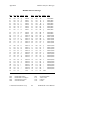
Appendix A
Multiline Interface Messages ....................................................... A-1
Appendix B
Status and Message Information ................................................B-1
Status Bits................................................................................... B-1
S Mode ......................................................................... B-1
G Mode......................................................................... B-5
GPIB Error Codes....................................................................... B-7
SCSI Error Codes ....................................................................... B-10
Status Bytes ................................................................................B-12
Message Bytes ............................................................................B-13
Sense Keys..................................................................................B-16
Appendix C
Operation of the GPIB ....................................................................C-1
Types of Messages ..................................................................... C-1
Talkers, Listeners, and Controllers............................................. C-1
The Controller-In-Charge and System Controller ......................C-2
GPIB Signals and Lines..............................................................C-3
Data Lines ....................................................................C-3
Handshake Lines ..........................................................C-3
NRFD* (not ready for data)........................... C-3
NDAC* (not data accepted)........................... C-4
DAV* (data valid) ......................................... C-4
Interface Management Lines ........................................C-4
ATN* (attention) ........................................... C-4
IFC* (interface clear)..................................... C-4
REN* (remote enable) ................................... C-4
SRQ* (service request) ..................................C-4
EOI* (end or identify) ................................... C-5
Physical and Electrical Characteristics....................................... C-5
Configuration Requirements....................................................... C-9
Related Documentation ..............................................................C-9
GPIB-SCSI-A User Manual
xii
© National Instruments Corp.
Contents
Appendix D
Operation of the SCSI ..................................................................... D-1
History of the SCSI..................................................................... D-1
Operation of the SCSI................................................................. D-1
Communication on the SCSI ......................................................D-5
SCSI Signals............................................................................... D-6
Data Bus Signals ..........................................................D-8
Control Signals............................................................. D-9
Handshake Lines............................................D-9
Phase Control Lines....................................... D-9
Miscellaneous Control Lines ......................... D-9
The TERMPWR Pin..................................................... D-10
Physical and Electrical Characteristics....................................... D-11
Configuration Restrictions..........................................................D-11
Appendix E
Parallel Polling ................................................................................... E-1
Operation ....................................................................................E-1
Configuration..............................................................................E-1
Issuing Remote Configurations in S Mode................................. E-3
Issuing Local Configurations in S Mode ....................................E-4
The Parallel Poll ......................................................................... E-5
S Mode Example......................................................................... E-5
Appendix F
Customer Communication ............................................................F-1
Glossary................................................................................................. G-1
Index ................................................................................................. Index-1
© National Instruments Corp.
xiii
GPIB-SCSI-A User Manual
Contents
Figures
Figure 1-1.
Figure 1-2.
Figure 1-3.
Figure 1-4.
Figure 1-5.
Figure 1-6.
GPIB-SCSI-A........................................................................1-1
The GPIB-SCSI-A Rear Panel ..............................................1-8
The SCSI Connector and Signal Designations......................1-9
The GPIB Connector and Signal Assignments ..................... 1-10
SCSI Computer Controlling GPIB Devices ..........................1-11
A SCSI Bus Connected to a GPIB Controller....................... 1-12
Figure 2-1.
Figure 2-2.
Figure 2-3.
Figure 2-4.
Figure 2-5.
SW1 Default Mode Switch Settings ..................................... 2-2
SW2 Default Switch Settings ................................................2-5
SW2 Sample Setting for G Mode..........................................2-7
GPIB-SCSI-A Physically Located at End of SCSI Bus ........2-9
GPIB-SCSI-A Not Physically Located at End of
SCSI Bus............................................................................... 2-10
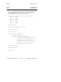
Figure 4-1. Command Descriptor Block Example................................... 4-2
Figure 6-1. Serial Poll Status Byte........................................................... 6-24
Figure 7-1. Valid Bits of mask................................................................. 7-13
Figure C-1. The GPIB Connector and Signal Assignments..................... C-6
Figure C-2. Linear Configuration ............................................................C-7
Figure C-3. Star Configuration ................................................................C-8
Figure D-1. Standard 50-Pin SCSI Connector......................................... D-7
Figure D-2. Daisy-Chain Configuration of the SCSI Bus ....................... D-11
Tables
Table 1-1.
Table 1-2.
Table 1-3.
Table 1-4.
Table 1-5.
Electrical Characteristics ........................................................1-4
Environmental Characteristics................................................1-5
Physical Characteristics ..........................................................1-5
Maximum Transfer Rates ....................................................... 1-6
LED Descriptions ................................................................... 1-7
Table 2-1.
Table 2-2.
Table 2-3.
Table 2-4.
Configuration Parameters for Switches 1 through 3............... 2-3
Configuration Parameters for Switches 4 through 8............... 2-4
Possible Configurations for SW2 in S Mode ......................... 2-6
Possible Configurations for SW2 in G Mode......................... 2-8
GPIB-SCSI-A User Manual
xiv
© National Instruments Corp.
Contents
Table 4-1.
Table 4-2.
Table 4-3.
Table 4-4.
Table 4-5.
GPIB Characteristics ..............................................................4-10
GPIB Function Group............................................................. 4-11
SCSI Functions....................................................................... 4-14
General Use Functions ........................................................... 4-14
GPIB-SCSI-A S Mode Functions........................................... 4-15
Table 5-1. Buffering Methods for Data Transfer Commands..................5-27
Table 5-2. Data Transfer Termination Methods ......................................5-31
Table 5-3. Inquiry Data Format for the GPIB-SCSI-A............................5-42
Table 5-4. Sense Data Format for the GPIB-SCSI-A ..............................5-73
Table 5-5. GPIB-SCSI-A Sense Keys ..................................................... 5-74
Table 5-6. GPIB-SCSI-A Status Conditions............................................5-92
Table 5-7. GPIB Error Conditions ........................................................... 5-93
Table 5-8. SCSI Error Conditions............................................................5-94
Table 5-9. Timeout Limit Values............................................................. 5-98
Table 5-10. Wait Mask Values ................................................................5-106
Table 6-1.
Table 6-2.
Table 6-3.
Table 6-4.
Table 6-5.
SCSI Functions....................................................................... 6-13
SCSI Configuration Functions ............................................... 6-17
GPIB Configuration Function ................................................6-18
General Use Functions ........................................................... 6-18
GPIB-SCSI-A G Mode Functions ..........................................6-19
Table 7-1.
Table 7-2.
Table 7-3.
Table 7-4.
Table 7-5.
Buffering Methods for High-Level Commands. ....................7-14
SRQ Mask Bits ....................................................................... 7-91
GPIB-SCSI-A Status Conditions............................................7-95
GPIB Error Conditions ........................................................... 7-97
SCSI Error Conditions............................................................7-98
Table D-1. Data Bus Signals....................................................................D-8
Table E-1. Parallel Poll Message Bits......................................................E-3
© National Instruments Corp.
xv
GPIB-SCSI-A User Manual
About This Manual
This manual describes the function of the GPIB-SCSI-A and contains
information concerning its operation and programming.
The GPIB-SCSI-A is one of the National Instruments family of IEEE 488
support products. These products are small, high-performance, converters,
and controllers packaged in all-metal cases.
Organization of This Manual
This manual is organized as follows:
•
Chapter 1, Description of the GPIB-SCSI-A, contains general
information about the National Instruments GPIB-SCSI-A, the
IEEE 488 port, and the SCSI port. This chapter also lists all the
components and accessories as well as electrical, environmental, and
physical specifications of the GPIB-SCSI-A, and explains the two
modes of operation for the GPIB-SCSI-A.
•
Chapter 2, Installation and Configuration of the GPIB-SCSI-A,
contains the steps for installing and configuring the GPIB-SCSI-A in S
mode and G mode.
•
Chapter 3, Technical Information, contains detailed information for
advanced users who want to increase the power of the GPIB-SCSI-A.
•
Chapter 4, Programming in S Mode, explains how to program the
GPIB-SCSI-A when operating in S mode. In this mode, the
GPIB-SCSI-A can be programmed from any operating system and
language that has access to a SCSI port. This chapter describes
programming messages, their format, and how they are processed,
along with the functions and function arguments that make up the
programming messages.
•
Chapter 5, S Mode Functions, contains a detailed description of each
S mode function. These functions are in alphabetical order for easy
reference.
© National Instruments Corp.
xvii
GPIB-SCSI-A User Manual
About This Manual
•
Chapter 6, Programming in G Mode, explains how to program the
GPIB-SCSI-A when operating in G mode. It describes programming
messages, their format, and how they are processed, along with the
functions and function arguments that make up the programming
messages. This chapter also explains how to communicate with your
SCSI device(s) through the GPIB-SCSI-A.
•
Chapter 7, G Mode Functions, contains a detailed description of each G
mode function. The functions are in alphabetical order for easy
reference and each function contains its syntax and purpose, as well as
some examples.
•
Appendix A, Multiline Interface Messages, contains an interface
message reference list, which describes the mnemonics and messages
that correspond to the interface functions.
•
Appendix B, Status and Message Information, describes the status and
error information that the GPIB-SCSI-A records as it executes each
programming message. Also described are the SCSI message bytes
that the GPIB-SCSI-A responds to or generates while operating, as well
as the Extended Sense keys that the GPIB-SCSI-A uses.
•
Appendix C, Operation of the GPIB, describes the operation of the
GPIB.
•
Appendix D, Operation of the SCSI, describes the operation of the
SCSI.
•
Appendix E, Parallel Polling, explains the use and operation of parallel
polls.
•
Appendix F, Customer Communication, contains forms you can use to
request help from National Instruments or to comment on our products
and manuals.
•
The Glossary contains an alphabetical list and description of terms used
in this manual including abbreviations, acronyms, metric prefixes,
mnemonics, and symbols.
•
The Index contains an alphabetical list of key terms and topics used in
this manual, including the page where each can be found.
GPIB-SCSI-A User Manual
xviii
© National Instruments Corp.
About This Manual
Conventions Used in This Manual
The following conventions are used in this manual:
italic
Italic text denotes emphasis, a cross reference, or
an introduction to a key concept.
monospace
Lowercase text in this font denotes text or
characters that are to be literally input from the
keyboard, sections of code, programming
examples, and syntax examples. This font is also
used for the proper names of disk drives, paths,
directories, programs, subprograms, subroutines,
device names, functions, variables, filenames,
and extensions, and for statements and comments
taken from program code.
IEEE 488 and
IEEE 488.2
IEEE 488 and IEEE 488.2 are used throughout
this manual to refer to the ANSI/IEEE Standard
488.1-1987 and the ANSI/IEEE Standard 488.2-1987,
respectively, which define the GPIB.
Related Documentation
The following documents contain information that you may find helpful as
you read this manual:
•
ANSI X3.131-1986, small computer system interface (SCSI).
•
ANSI/IEEE Standard 488.1-1987, IEEE Standard Digital Interface for
Programmable Instrumentation.
•
ANSI/IEEE Standard 488.2-1987, IEEE Standard Codes, Formats, Protocols,
and Common Commands
© National Instruments Corp.
xix
GPIB-SCSI-A User Manual
About This Manual
Customer Communication
National Instruments wants to receive your comments on our products and
manuals. We are interested in the applications you develop with our
products, and we want to help if you have problems with them. To make it
easy for you to contact us, this manual contains comment and configuration
forms for you to complete. These forms are in Appendix F, Customer
Communication, at the end of this manual.
GPIB-SCSI-A User Manual
xx
© National Instruments Corp.
Description of the GPIB-SCSI-A
Chapter 1
The GPIB-SCSI-A is an 8-bit microcomputer that operates as a full-function
IEEE 488/SCSI Controller. The GPIB-SCSI-A can turn any computer with
a SCSI port into a GPIB Talker/Listener/Controller or can make any device
on the SCSI bus look like a GPIB device.
The GPIB-SCSI-A has all the software and logic required to implement the
physical and electrical specifications of the IEEE 488.2 and the ANSI
X3T9.2 standards. It is able to interpret and execute commands that you
send to it over the GPIB or SCSI ports and perform all necessary GPIB-toSCSI protocol conversion.
What You Need to Get Started
One of the following boxes:
GPIB-SCSI-A, 100 to 120 VAC
GPIB-SCSI-A, 220 to 240 VAC
One of the following power cords:
U.S.A. standard power cord
Switzerland power cord
Australian power cord
Universal European power cord
North American power cord
U.K. power cord
Standard 50-pin SCSI-1 terminator
GPIB-SCSI-A User Manual
1-2
© National Instruments Corp.
Chapter 1
Description of the GPIB-SCSI-A
Optional Equipment
You can call National Instruments to order the following optional
equipment.
•
Rack-mount kit
Single (one unit)
Dual (two units)
•
Type SCSI-A cable
25-pin D-Sub to SCSI-1 (50-pin Champ)
—1 m, 2 m, 3 m, 4 m, or 5 m lengths
•
Type SCSI-G cable
SCSI-1 (50-pin) to SCSI-2 (50-pin)
—1 m or 2 m
•
Type SCSI-H cable
SCSI-1 (50-pin) to DEC VAXstation (68-pin)
—1 m or 2 m
•
Type SCSI-J cable
SCSI-1 (50-pin Champ) to SCSI-1 (50-pin Champ)
—1 m or 2 m lengths
•
Type SCSI-L cable
SCSI-1 (50-pin) to Sun-3/60 workstation port (68-pin D-shell)
—1 m or 2 m
•
Type SCSI-M cable
SCSI-1 (50-pin) to Macintosh Powerbook port
—0.5 m
•
Shielded GPIB cables*
GPIB Type X1 cables—1 m, 2 m, 4 m, or 8 m
GPIB Type X2 cables—1 m, 2 m, 4 m, or 8 m
*
To meet FCC emission limits for a Class A device, you must use a
shielded (Type X1 or X2) GPIB cable. Operating this equipment
with a non-shielded GPIB cable may cause interference to radio
and television reception in commercial areas.
© National Instruments Corp.
1-3
GPIB-SCSI-A User Manual
Description of the GPIB-SCSI-A
Chapter 1
Inspection
Before you install the GPIB-SCSI-A, inspect the shipping container and its
contents for damage. Retain the packaging material for possible inspection
or for reshipment.
If the equipment appears to be damaged, do not attempt to operate it.
Contact National Instruments for instructions. If the damage appears to
have been caused in shipment, file a claim with the carrier.
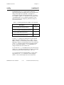
GPIB-SCSI-A Specifications
The following tables specify the electrical, environmental, and physical
characteristics of the GPIB-SCSI-A as well as the maximum transfer rates
for the GPIB-SCSI-A.
Table 1-1. Electrical Characteristics
Characteristic
Specification
Power Supply Unit
100 to 120 VAC ± 10%, 50 to 60 Hz, or
220 to 240 VAC ± 10%, 50 to 60 Hz
Current Requirement
100 to 120 VAC, 90 mA
220 to 240 VAC, 45 mA
Fuse Rating and Type
100 to 120 VAC, 200 mA UL/CSA approved
220 to 240 VAC, 125 mA IEC approved
GPIB-SCSI-A User Manual
1-4
© National Instruments Corp.
Chapter 1
Description of the GPIB-SCSI-A
Table 1-2. Environmental Characteristics
Characteristic
Specification
Operating Temperature
0° to 40° C
Storage Temperature
-20° to 70° C
Relative Humidity
10% to 90% noncondensing conditions
EMI
FCC Class A Verified
Table 1-3. Physical Characteristics
Characteristic
Specification
Overall Case Size
2.934 in. by 7.489 in. by 9.88 in.
(74.5 mm by 190.2 mm by 250.9 mm)
Case Material
All metal enclosure
Rack Mounting
Single or dual kits available
Weight
4 lb
(1.81 kg)
© National Instruments Corp.
1-5
GPIB-SCSI-A User Manual
Description of the GPIB-SCSI-A
Chapter 1
Table 1-4. Maximum Transfer Rates
Transfer Type
Transfer Rate
Buffered Transfer Rates:
SCSI Reads to Buffer Memory
1 Mbytes/sec
SCSI Writes from Buffer Memory
800 kbytes/sec
GPIB Reads to Buffer Memory
980 kbytes/sec
GPIB Writes from Buffer Memory
615 kbytes/sec
Straight-Through Transfer Rates:
GPIB Read/SCSI Write
800 kbytes/sec
GPIB Write/SCSI Read
615 kbytes/sec
Note: These numbers are the maximum rates that the hardware can
send/receive data. Software overhead will affect the actual
throughput of your system.
GPIB-SCSI-A User Manual
1-6
© National Instruments Corp.
Chapter 1
Description of the GPIB-SCSI-A
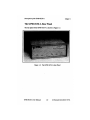
The GPIB-SCSI-A Front Panel
The front panel of the GPIB-SCSI-A is shown in Figure 1-1. Six status
Light Emitting Diodes (LEDs) are mounted on the GPIB-SCSI-A front
panel.
The LEDs show the current status of the GPIB-SCSI-A at all times.
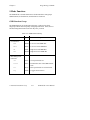
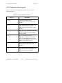
Table 1-5 describes each LED.
Table 1-5. LED Descriptions
LED
Indication
POWER
Indicates that power to the unit has been applied and the
ON/OFF switch is in the ON position.
READY
Indicates that the power-on self-test has passed successfully
and the unit is ready to operate.
TALK
Indicates that the GPIB-SCSI-A is configured as a GPIB
Talker.
LISTEN
Indicates that the GPIB-SCSI-A is configured as a GPIB
Listener.
SEND
Indicates that the GPIB-SCSI-A is sending data across the
SCSI.
RECEIVE
Indicates that the GPIB-SCSI-A is receiving data from the
SCSI.
© National Instruments Corp.
1-7
GPIB-SCSI-A User Manual
Chapter 1
Description of the GPIB-SCSI-A
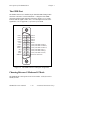
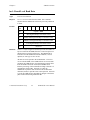
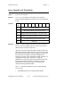
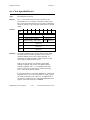
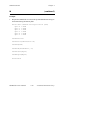
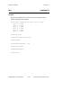
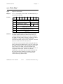
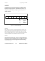
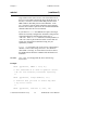
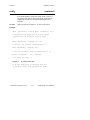
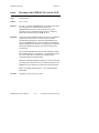
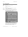
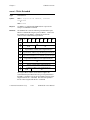
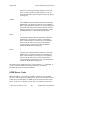
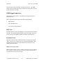
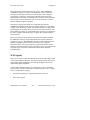
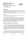
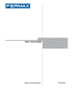
The SCSI Port
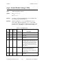
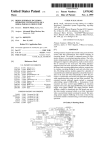
The SCSI port on the GPIB-SCSI-A uses a standard SCSI-1 50 pin shielded
female connector with locking clamps. A diagram of the SCSI connector
and the signals supported is shown in Figure 1-3 (a * suffix indicates that
the signal is active low). For a description of each of the signal lines, refer
to Appendix D, Operation of the SCSI.
ground
ground
ground
ground
ground
ground
ground
ground
ground
ground
ground
reserved
open
reserved
ground
ground
ground
ground
ground
ground
ground
ground
ground
ground
ground
1
2
3
4
5
6
7
8
9
10
11
12
13
14
15
16
17
18
19
20
21
22
23
24
25
26
27
28
29
30
31
32
33
34
35
36
37
38
39
40
41
42
43
44
45
46
47
48
49
50
SDB0*
SDB1*
SDB2*
SDB3*
SDB4*
SDB5*
SDB6*
SDB7*
SDBP*
ground
ground
reserved
TERMPWR
reserved
ground
ATN*
ground
BSY*
ACK*
RST*
MSG*
SEL*
C/D*
REQ*
I/O*
Figure 1-3. The SCSI Connector and Signal Designations
© National Instruments Corp.
1-9
GPIB-SCSI-A User Manual
Description of the GPIB-SCSI-A
Chapter 1
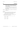
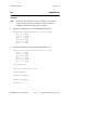
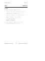
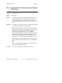
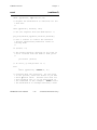
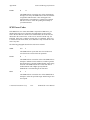
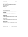
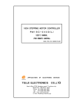
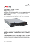
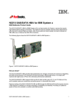
The GPIB Port
The GPIB connector is a standard 24-pin shielded AMP Champ female
connector with metric screwlock hardware. A diagram of the GPIB
connector and the signals supported is shown in Figure 1-4 (a * suffix
indicates that the signal is active low). For a description of each of the
signal lines, refer to Appendix C, Operation of the GPIB.
DIO1*
DIO2*
DIO3*
DIO4*
EOI*
DAV*
NRFD*
NDAC*
IFC*
SRQ*
ATN*
SHIELD
1
2
3
4
5
6
7
8
9
10
11
12
13
14
15
16
17
18
19
20
21
22
23
24
DIO5*
DIO6*
DIO7*
DIO8*
REN*
GND (TW PAIR W/DAV*)
GND (TW PAIR W/NRFD*)
GND (TW PAIR W/NDAC*)
GND (TW PAIR W/IFC*)
GND (TW PAIR W/SRQ*)
GND (TW PAIR W/ATN*)
SIGNAL GROUND
Figure 1-4. The GPIB Connector and Signal Assignments
Choosing Between S Mode and G Mode
The GPIB-SCSI-A can operate in one of two modes: SCSI (S) mode or
GPIB (G) mode.
GPIB-SCSI-A User Manual
1-10
© National Instruments Corp.
Chapter 1
Description of the GPIB-SCSI-A
You will be connecting the GPIB-SCSI-A to both a SCSI device or system
and a GPIB device or system. The mode of operation is determined from
the method by which the GPIB-SCSI-A receives its programming
instructions.
If you are using the GPIB-SCSI-A to communicate with and/or control
GPIB devices from a SCSI host, the GPIB-SCSI-A receives its
programming instructions from the SCSI host and is configured as a SCSI
device. Therefore, set the GPIB-SCSI-A to operate in S mode.
If, on the other hand, you are using the GPIB-SCSI-A to communicate with
SCSI devices from a GPIB host, the GPIB-SCSI-A receives its
programming instructions from the GPIB host and is configured as a GPIB
device. Therefore, set the GPIB-SCSI-A to operate in G mode.
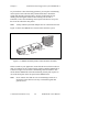
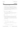
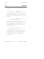
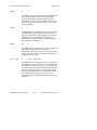
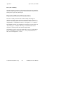
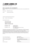
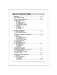
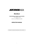
Figure 1-5 shows the GPIB-SCSI-A operating in S mode where a personal
computer with a SCSI port is controlling a GPIB system.
SCSI tape
drive
SCSI disk
drive
GPIB
cable
SCSI host
GPIB plotter
GPIB-SCSI-A
GPIB device
Figure 1-5. SCSI Computer Controlling GPIB Devices
© National Instruments Corp.
1-11
GPIB-SCSI-A User Manual
Description of the GPIB-SCSI-A
Chapter 1
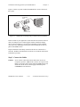
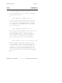
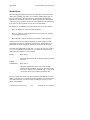
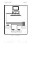
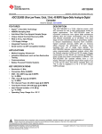
Figure 1-6 shows the GPIB-SCSI-A operating in the G mode where the
GPIB-SCSI-A enables SCSI devices to be accessed by a GPIB Controller.
GPIB
printer
GPIB
cable
SCSI
scanner
SCSI
cable
SCSI disk
drive
GPIB-SCSI-A
GPIB
Controller
Figure 1-6. A SCSI Bus Connected to a GPIB Controller
GPIB-SCSI-A User Manual
1-12
© National Instruments Corp.
Chapter 2
Installation and Configuration of the
GPIB-SCSI-A
This chapter contains the steps for installing and configuring the
GPIB-SCSI-A in S mode and G mode.
Use this chapter to configure your GPIB-SCSI-A for operation.
Installation
There are four basic steps to installing the GPIB-SCSI-A.
1. Verify the voltage requirement.
2. Configure the operating characteristics.
3. Connect the cables.
4. Switch on your GPIB-SCSI-A and power on your system.
These steps are described in more detail in the following sections.
Step 1. Verify the Voltage Requirement
The GPIB-SCSI-A is shipped from the factory with a 100 to 120 VAC or
220 to 240 VAC power supply. Verify that the voltage specified on the
label on the bottom of the GPIB-SCSI-A matches the voltage that is
supplied in your area.
Caution:
Operating the GPIB-SCSI-A at any voltage other than the one
specified could damage the unit. Replacement fuses should be the
proper type and rating. Refer to Chapter 1, the section entitled
GPIB-SCSI-A Specifications, for fuse information.
© National Instruments Corp.
2-1
GPIB-SCSI-A User Manual
Installation and Configuration of the GPIB-SCSI-A
Chapter 2
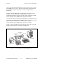
Step 2. Configure the Operating Characteristics
The GPIB-SCSI-A is shipped from the factory configured to operate in S
mode. Optional parity checking on the SCSI port is disabled. The SCSI ID
that the GPIB-SCSI-A responds to is set at 5, and the primary GPIB address
is set at 0. Additionally, the GPIB-SCSI-A is shipped from the factory with
a SCSI terminating resistor pack installed. Depending on your system, you
may want to remove it.
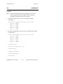
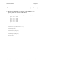
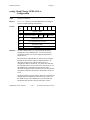
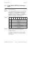
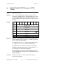
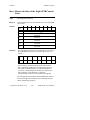
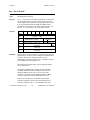
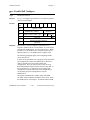
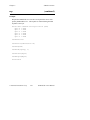
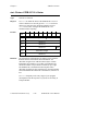
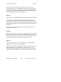
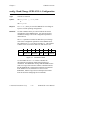
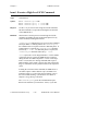
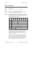
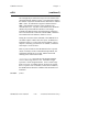
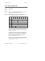
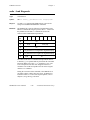
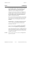
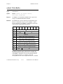
Configuration Switch Settings for SW1
The DIP switch at location SW1 on the rear panel is used to configure the
power-on primary GPIB address and SCSI ID of the GPIB-SCSI-A. The
DIP switch has eight configuration switches.
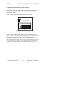
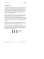
The factory default setting is shown in Figure 2-1. In this figure, the black
side of the switch is the side of the switch you press down.
Key
= side you press down
1 2 3 4 5 6 7 8
O
N
SW1
Figure 2-1. SW1 Default Mode Switch Settings
Figure 2-1 shows the factory default setting of the GPIB-SCSI-A for switch
SW1. Switches 1 through 3 are ON, OFF, ON, respectively, to indicate that
the SCSI ID of the GPIB-SCSI-A is 5. Switches 4 through 8 are OFF to
indicate that the primary GPIB address of the GPIB-SCSI-A is 0.
GPIB-SCSI-A User Manual
2-2
© National Instruments Corp.
Chapter 2
Installation and Configuration of the GPIB-SCSI-A
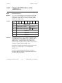
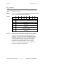
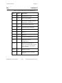
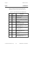
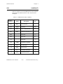
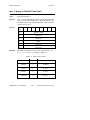
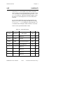
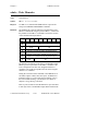
Tables 2-1 and 2-2 show the possible configurations of the eight switches
and what each configuration indicates.
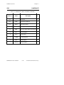
Note: The factory default settings are in bold italic.
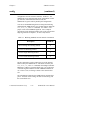
Table 2-1. Configuration Parameters for Switches 1 through 3
1
OFF
OFF
OFF
OFF
ON
ON
ON
ON
Switches
2
OFF
OFF
ON
ON
OFF
OFF
ON
ON
© National Instruments Corp.
Indication
3
OFF
ON
OFF
ON
OFF
ON
OFF
ON
2-3
SCSI ID of 0
SCSI ID of 1
SCSI ID of 2
SCSI ID of 3
SCSI ID of 4
SCSI ID of 5
SCSI ID of 6
SCSI ID of 7
GPIB-SCSI-A User Manual
Installation and Configuration of the GPIB-SCSI-A
Chapter 2
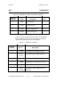
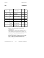
Table 2-2. Configuration Parameters for Switches 4 through 8
Switches
2
1
OFF
OFF
OFF
OFF
OFF
OFF
OFF
OFF
OFF
OFF
OFF
OFF
OFF
OFF
OFF
OFF
ON
ON
ON
ON
ON
ON
ON
ON
ON
ON
ON
ON
ON
ON
ON
ON
OFF
OFF
OFF
OFF
OFF
OFF
OFF
OFF
ON
ON
ON
ON
ON
ON
ON
ON
OFF
OFF
OFF
OFF
OFF
OFF
OFF
OFF
ON
ON
ON
ON
ON
ON
ON
ON
OFF
OFF
OFF
OFF
ON
ON
ON
ON
OFF
OFF
OFF
OFF
ON
ON
ON
ON
OFF
OFF
OFF
OFF
ON
ON
ON
ON
OFF
OFF
OFF
OFF
ON
ON
ON
ON
OFF
OFF
ON
ON
OFF
OFF
ON
ON
OFF
OFF
ON
ON
OFF
OFF
ON
ON
OFF
OFF
ON
ON
OFF
OFF
ON
ON
OFF
OFF
ON
ON
OFF
OFF
ON
ON
GPIB-SCSI-A User Manual
Indication
3
OFF
ON
OFF
ON
OFF
ON
OFF
ON
OFF
ON
OFF
ON
OFF
ON
OFF
ON
OFF
ON
OFF
ON
OFF
ON
OFF
ON
OFF
ON
OFF
ON
OFF
ON
OFF
ON
2-4
GPIB Primary address 0
GPIB Primary address 1
GPIB Primary address 2
GPIB Primary address 3
GPIB Primary address 4
GPIB Primary address 5
GPIB Primary address 6
GPIB Primary address 7
GPIB Primary address 8
GPIB Primary address 9
GPIB Primary address 10
GPIB Primary address 11
GPIB Primary address 12
GPIB Primary address 13
GPIB Primary address 14
GPIB Primary address 15
GPIB Primary address 16
GPIB Primary address 17
GPIB Primary address 18
GPIB Primary address 19
GPIB Primary address 20
GPIB Primary address 21
GPIB Primary address 22
GPIB Primary address 23
GPIB Primary address 24
GPIB Primary address 25
GPIB Primary address 26
GPIB Primary address 27
GPIB Primary address 28
GPIB Primary address 29
GPIB Primary address 30
GPIB Primary address 0
© National Instruments Corp.
Chapter 2
Installation and Configuration of the GPIB-SCSI-A
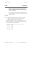
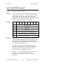
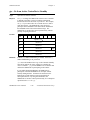
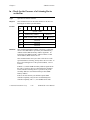
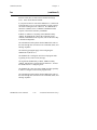
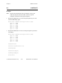
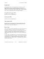
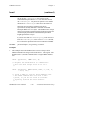
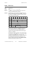
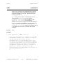
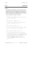
Configuration Switch Settings for SW2 in S Mode
The DIP switch at location SW2 on the rear panel is used to configure the
mode of operation for the GPIB-SCSI-A. The DIP switch has eight
configuration switches.
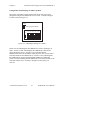
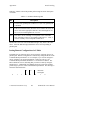
Figure 2-2 shows the factory default switch settings for SW2.
Key
= side you press down
1 2 3 4 5 6 7 8
O
N
SW2
Figure 2-2. SW2 Default Switch Settings
Switch 8 is OFF, indicating that the GPIB-SCSI-A will be operating in S
mode. Switch 7 is ON, indicating that the GPIB-SCSI-A will neither notice
nor report SCSI parity errors. Switch 6 is ON, indicating that the
GPIB-SCSI-A will buffer data during data transfer commands. Switch 5 is
OFF, indicating that the GPIB-SCSI-A will complete all data requests to the
exact count specified. Switches 4 is ON, indicating that double buffering
will be used. Switches 1 through 3 are OFF because they are reserved.
© National Instruments Corp.
2-5
GPIB-SCSI-A User Manual
Installation and Configuration of the GPIB-SCSI-A
Chapter 2
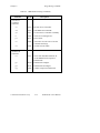
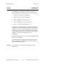
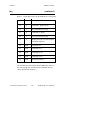
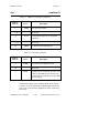
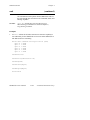
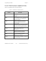
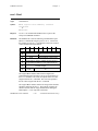
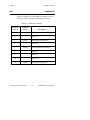
Table 2-3 shows the possible configurations of the eight switches in S mode
and what each configuration indicates.
Table 2-3. Possible Configurations for SW2 in S Mode
Switch
Position
8
OFF
S mode
7
OFF
SCSI parity generation/checking enabled
ON
SCSI parity generation/checking
disabled
OFF
Buffering disabled
ON
Buffering enabled
OFF
Complete SCSI data phases
ON
Do not complete SCSI data phases
OFF
If buffering is enabled, use single
buffering
ON
If buffering is enabled, use double
buffering
OFF
Reserved and should remain OFF
6
5
4
1-3
GPIB-SCSI-A User Manual
Indication
2-6
© National Instruments Corp.
Chapter 2
Installation and Configuration of the GPIB-SCSI-A
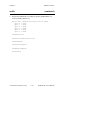
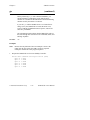
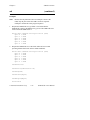
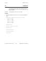
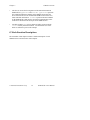
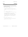
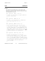
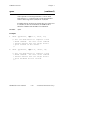
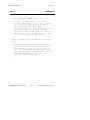
Configuration Switch Settings for SW2 in G Mode
The setting of the DIP switch at location SW2 on the rear panel can be
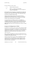
changed to configure the GPIB-SCSI-A for G mode. A sample setting for
G mode is shown in Figure 2-3.
Key
= side you press down
1 2 3 4 5 6 7 8
O
N
SW2
Figure 2-3. SW2 Sample Setting for G Mode
Switch 8 is ON, indicating that the GPIB-SCSI-A will be operating in G
mode. Switch 7 is OFF, indicating that the GPIB-SCSI-A detects and
reports SCSI parity errors. Switch 6 is ON, indicating that the
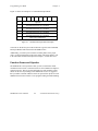
GPIB-SCSI-A asserts the SCSI RST* signal at power on to reset the entire
SCSI bus attached to the GPIB-SCSI-A. Switch 5 is OFF, indicating that
the GPIB-SCSI-A responds to Major/Minor GPIB device addressing.
Switch 4 is OFF indicating that the GPIB-SCSI-A will not assert EOI on the
serial poll response byte. Switches 1 through 3 are OFF as they are
reserved.
© National Instruments Corp.
2-7
GPIB-SCSI-A User Manual
Installation and Configuration of the GPIB-SCSI-A
Chapter 2
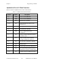
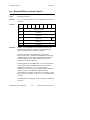
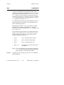
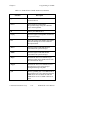
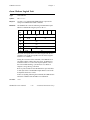
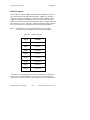
Table 2-4 shows the possible configurations of the eight switches in G
mode and what each configuration indicates.
Table 2-4. Possible Configurations for SW2 in G Mode
Switch
Position
Indication
8
ON
G mode
7
OFF
SCSI parity generation/checking
enabled
ON
SCSI parity generation/checking disabled
OFF
Do not assert the SCSI RST* signal at
power on
ON
Assert the SCSI RST* signal at power on
OFF
Major/minor GPIB addressing used
ON
Secondary addressing used
OFF
Do not assert EOI with serial poll
response
ON
Assert EOI with serial poll response
OFF
Reserved and should remain OFF
6
5
4
1-3
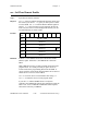
SCSI Terminating Resistors
Because of its high-speed capabilities, the SCSI bus is sensitive to the
electrical characteristics of the SCSI cabling. When a signal is sent through
the SCSI bus, it bounces back and creates echoes along the cabling.
Devices in the middle of the daisy-chained SCSI bus receive these signal
echoes.
GPIB-SCSI-A User Manual
2-8
© National Instruments Corp.
Chapter 2
Installation and Configuration of the GPIB-SCSI-A
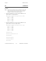
To prevent these echoes from being generated, you can place a terminating
resistor pack at each end of the daisy-chained SCSI bus to absorb the
signals and eliminate potential echoes. Because SCSI signals are not
reliably passed along the SCSI bus after reaching a device with a
terminator, remove the terminating resistor pack on all devices except for
the two at the ends of the daisy-chain.
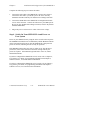
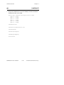
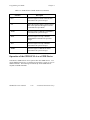
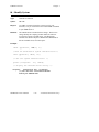
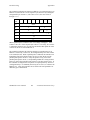
Note:
A daisy-chained system has multiple devices connected to the host.
Figure 2-4 shows the GPIB-SCSI-A located at the end of the system.
SCSI host
SCSI tape
drive
SCSI disk
drive
GPIB-SCSI-A
Figure 2-4. GPIB-SCSI-A Physically Located at End of SCSI Bus
If this is similar to your application, ensure that all devices between the two
ends (for example, the two ends being the SCSI host and the GPIB-SCSI-A
as shown in Figure 2-4) do not have terminating resistors installed. Also
ensure that the GPIB-SCSI-A has the terminating resistor pack in place on
one of the SCSI ports on the rear panel of the GPIB-SCSI-A.
Note:
Never connect more than two sets of terminating resistors on a
SCSI bus as more than two sets may overload the signals and
generate errors.
© National Instruments Corp.
2-9
GPIB-SCSI-A User Manual
Installation and Configuration of the GPIB-SCSI-A
Chapter 2
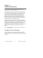
Figure 2-5 shows a system in which the GPIB-SCSI-A is not at the end of
the system.
SCSI disk
drive
SCSI host
SCSI tape
drive
GPIB-SCSI-A
Figure 2-5. GPIB-SCSI-A Not Physically Located at End of SCSI Bus
If this is similar to your application, ensure that all devices between the two
ends (for example, the two ends being the SCSI host and the SCSI tape
drive as shown in Figure 2-5) do not have terminating resistors installed.
Also remove the terminating resistor pack from the SCSI port on the rear
panel of the GPIB-SCSI-A.
Proper termination is absolutely essential to the devices connected on a
SCSI bus. Read the documentation for each device to find out what kind of
termination it provides.
Step 3. Connect the Cables
Caution:
Never connect or disconnect SCSI cables when any device
(computer, tape drive, GPIB-SCSI-A, and so on) is powered on.
Doing so can cause fuses to blow inside the GPIB-SCSI-A and
inside other SCSI devices which supply termination power
(TERMPWR) to the SCSI bus.
GPIB-SCSI-A User Manual
2-10
© National Instruments Corp.
Chapter 2
Installation and Configuration of the GPIB-SCSI-A
Complete the following steps to connect the cables:
1.
Connect the SCSI cable to the GPIB-SCSI-A and securely fasten it.
Connect the other end to your SCSI system. Be sure to use only
shielded SCSI cables and obey all ANSI X3T9.2 cabling restrictions.
2.
Connect the GPIB cable to the GPIB-SCSI-A and tighten the thumb
screws on the connector. Connect the other end to your GPIB system.
Be sure to obey all IEEE 488 cabling restrictions, and use only doubleshielded GPIB cables.
3.
Plug in the power cord into an AC outlet of the correct voltage.
Step 4. Switch On Your GPIB-SCSI-A and Power on
Your System
Power on your GPIB-SCSI-A by using the rocker switch on the rear panel.
The POWER LED should come on immediately and the READY indicator
on the front panel should come on after the GPIB-SCSI-A has passed its
power-on self-test, indicating the unit is ready for operation.
If the READY indicator does not come on within 10 sec after the unit is
powered on, recheck all connections and switch settings and retry the
power-on sequence. If the READY light still fails to come on, contact
National Instruments.
If you have configured the GPIB-SCSI-A for S mode, refer to Chapter 4,
Programming in S Mode, for programming information and Chapter 5,
S Mode Functions, for S mode function information.
If you have configured the GPIB-SCSI-A for G mode, refer to Chapter 6,
Programming in G Mode, for programming information and Chapter 7,
G Mode Functions, for G mode function information.
© National Instruments Corp.
2-11
GPIB-SCSI-A User Manual
Chapter 3
Technical Information
This chapter contains detailed information for advanced users who
want to increase the power of the GPIB-SCSI-A.
The GPIB-SCSI-A is actually a powerful 8-bit microcomputer tailored for
use as an IEEE 488-to-SCSI protocol controller. The operating system of
the unit is contained in Read-Only Memory (ROM) and 256 kilobytes of
Dynamic Random-Access Memory (DRAM). The GPIB-SCSI-A
microprocessor operates at 10 MHz and contains an integrated Direct
Memory Access (DMA) controller for high-speed data transfers from the
GPIB and SCSI circuitry. The processor also contains an integrated
memory management unit, a DRAM refresh controller, a clock generator, a
programmable timer unit, and an interrupt controller.
All GPIB functionality is provided by a NAT4882 application-specific
integrated circuit (ASIC) GPIB Controller chip, which is programmed and
maintained by the operating system. All SCSI functionality is provided by
an LSI SCSI controller chip, which is also programmed and maintained by
the operating system. Both the GPIB and SCSI ports use interrupt
conditions to process important events on either bus. The remainder of this
chapter contains additional technical information for each mode of
operation.
Note:
Unless stated otherwise, all numbers presented in this chapter are
in decimal notation.
Assumption of Previous Knowledge
This chapter assumes that you have a basic knowledge of the SCSI bus. If
you are a first-time user or you would like to review the basics, refer to
Appendix D, Operation of the SCSI, for a history of and a basic introduction
to the SCSI.
© National Instruments Corp.
3-1
GPIB-SCSI-A User Manual
Technical Information
Chapter 3
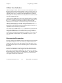
Buffering Methods
In both S mode and G mode, the GPIB-SCSI-A supports three different
methods of buffering data transferred between the GPIB and SCSI ports. In
S mode, the buffering method can be chosen using switches 4 and 6 of
SW2, or by using the config command. In G mode, the GPIB-SCSI-A
powers up using the straight-through method, but this can be changed by
using the config command.
When using the straight-through method, the GPIB-SCSI-A does not use
the DRAM buffer to hold data transferred between the ports. The DMA
controller transfers each byte directly from one port to the other, without
using the DRAM buffer.
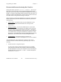
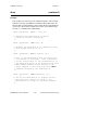
When using the single buffering method, the GPIB-SCSI-A uses the
available DRAM buffer space as a single buffer for data. During every data
transfer, it first fills the buffer with data from the source port. Then, it
writes this data out to the destination port. If there is more data available, it
fills the buffer from the source port again, and writes it out to the
destination port. This process continues until all available data has been
transferred.
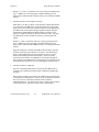
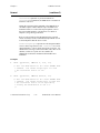
When using the double buffering method, the GPIB-SCSI-A splits the
available DRAM buffer space into two distinct buffers. During every data
transfer, it first fills the first buffer with data from the source port. Then, it
simultaneously writes this data to the destination port while it fills the
second buffer with data from the source port. If there is more data
available, it fills the first buffer from the source port while it writes data
from the second buffer to the destination port. The buffers are switched like
this until all the available data has been read, after which the last buffer
filled is written out to the destination port.
When the GPIB-SCSI-A powers up, the number of bytes of DRAM buffer
space is 224 kilobytes. This means that if double buffering is used, each of
the two buffers are 112 kilobytes in size. If a smaller size is desired, it can
be changed using the config command.
GPIB-SCSI-A User Manual
3-2
© National Instruments Corp.
Chapter 3
Technical Information
S Mode Operation
When operating in S mode, the GPIB-SCSI-A appears as a SCSI target
device on the SCSI system. In this mode, any SCSI device that can perform
Initiator abilities (that is, the ability to select, command, and communicate
with targets) on the SCSI can use the GPIB-SCSI-A to control a GPIB
system of which the GPIB-SCSI-A is a part.
In the following paragraphs, the term Initiator refers to the SCSI device that
performs Initiator duties. The term Target refers to the SCSI device that is
commanded by the Initiator to perform specific activities.
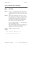
Configuration Switches at SW2
This section describes the purpose of each configuration switch located at
SW2 on the GPIB-SCSI-A during S mode operation.
Switch 7
Switch 7 determines whether or not the GPIB-SCSI-A notifies users of the
error condition created if the SCSI data bus parity is incorrect when the
GPIB-SCSI-A reads data from the SCSI. Since the parity error will only be
valid on SCSI reads, this error could occur in the Selection, Command, Data
Out, or Message Out phase, as all these phases read data from the SCSI.
The default setting of Switch 7 is ON, parity error detection and reporting
disabled.
Switch 7 ON
If Switch 7 is ON, the GPIB-SCSI-A neither detects nor reports parity
errors.
© National Instruments Corp.
3-3
GPIB-SCSI-A User Manual
Technical Information
Chapter 3
Switch 7 OFF
If Switch 7 is OFF, parity error detection and notification is enabled. Upon
detection of the parity error, the GPIB-SCSI-A will complete the command
as if nothing were wrong and set the status byte returned to the Initiator
during the Status phase to CHECK CONDITION and the Extended Sense
key to ERROR. To understand the error reporting technique employed on
the GPIB-SCSI-A during S mode, see the S Mode Error Indication section
in Chapter 4, Programming in S Mode.
Because the GPIB-SCSI-A does not terminate the processing of a command
immediately upon detection of a parity error and the error indication is
identical for each of the possible phases in which the parity error can occur,
there is no way to know in which phase the error occurred. Therefore, it is
recommended to issue the command again.
The parity error is very rare if you are using correct SCSI cabling. If you
are receiving this error often, and you are using properly shielded SCSI
cabling, recheck all SCSI connections within your system to ensure proper
connection. If this does not solve the problem and you are sure everything
else is performing as it should, contact National Instruments for further
assistance.
Switch 6
Switch 6 determines whether or not the GPIB-SCSI-A buffers data
transferred during brd, bwrt, rd, and wrt commands.
The default setting of Switch 6 is ON, buffering enabled.
Switch 6 ON
If Switch 6 is ON, the GPIB-SCSI-A buffers data transferred during the
brd, bwrt, rd, or wrt commands. Switch 4 is used to determine what
method of buffering will be used.
Switch 6 OFF
If Switch 6 is OFF, the GPIB-SCSI-A does not buffer data transferred
during the brd, bwrt, rd, or wrt commands. The straight-through
method is used to transfer data from one port to the other.
GPIB-SCSI-A User Manual
3-4
© National Instruments Corp.
Chapter 3
Technical Information
Switch 5
Switch 5 determines whether or not the GPIB-SCSI-A completes the SCSI
data transfers to the specified count. That is, if a rd or brd command is
issued and something occurs that would create a short count (an error, a
device clear, or END detected), the GPIB-SCSI-A sends all the valid data to
the SCSI Initiator followed by a number of null bytes (0) equal to the
difference of the original count requested and the actual count transferred.
Likewise, if a cmd, wrt, or bwrt command is issued and something
occurs that would create a short count (an error or a device clear), the
GPIB-SCSI-A stops attempting to send data to the GPIB and reads in and
discards the rest of the SCSI data.
The default setting of Switch 5 is OFF, complete SCSI data transfers to the
specified count.
Switch 5 ON
Setting configuration Switch 5 ON causes the GPIB-SCSI-A to immediately
change into the Status phase from a data transfer phase in the event of a
short count instead of completing SCSI activity to the specified length.
Switch 5 OFF
If Switch 5 is OFF, the GPIB-SCSI-A completes the SCSI Data Transfer
phase to the specified length.
Switch 4
If Switch 6 is ON, Switch 4 determines which buffering method to use
during brd, bwrt, rd, and wrt commands. If Switch 6 is OFF, Switch 4
has no meaning.
The default setting of Switch 4 is ON, double buffering enabled.
Switch 4 ON
If Switch 4 and Switch 6 are ON, the GPIB-SCSI-A uses the double
buffering method to buffer data transferred during the brd, bwrt, rd, and
wrt commands.
© National Instruments Corp.
3-5
GPIB-SCSI-A User Manual
Technical Information
Chapter 3
Switch 4 OFF
If Switch 4 is OFF and Switch 6 is ON, the GPIB-SCSI-A uses the single
buffering method to buffer data transferred during the brd, bwrt, rd, and
wrt commands.
Switches 1 Through 3
Switches 1 through 3 are reserved for future use and should remain in the
factory default position of OFF.
G Mode Operation
When operating in G mode, the GPIB-SCSI-A appears as a GPIB device on
the GPIB system. In this mode, any GPIB device attached to the GPIB
system of which the GPIB-SCSI-A is a part can use the GPIB-SCSI-A to
control a SCSI system attached to the GPIB-SCSI-A.
Configuration Switches at SW2
This section describes the purpose of each configuration switch located at
SW2 on the GPIB-SCSI-A during G mode operation.
Switch 7
Switch 7 determines whether or not the GPIB-SCSI-A notifies users of the
error condition created if the SCSI data bus parity is incorrect when the
GPIB-SCSI-A reads data from the SCSI. Because the parity error is only
valid on SCSI reads, this error can occur in the Reselection, Data In, or
Message In phase, as all these phases read data from the SCSI.
Switch 7 ON
If Switch 7 is ON, the GPIB-SCSI-A neither detects nor reports parity
errors.
GPIB-SCSI-A User Manual
3-6
© National Instruments Corp.
Chapter 3
Technical Information
Switch 7 OFF
Setting configuration Switch 7 OFF enables parity error detection and
notification. Upon detection of the parity error, the GPIB-SCSI-A
completes the command as if nothing were wrong to prevent the locking up
of the SCSI. After the operation is complete, the GPIB-SCSI-A reports an
error condition by setting the ERR bit in the 16-bit internal status word of
the GPIB-SCSI-A. SCERR is set to EPAR for a parity error. To
understand the error reporting technique employed on the GPIB-SCSI-A in
G mode, see the Status and Error Information section in Chapter 6,
Programming in G Mode.
Because the GPIB-SCSI-A does not terminate the processing of a command
immediately upon detection of a parity error and the error indication is
identical for each of the possible phases in which the parity error can occur,
there is no way to know in which phase the error occurred. Therefore, it is
recommended to issue the command again.
The parity error is very rare if you are using correct SCSI cabling. If you
are receiving this error often, and you are using proper, shielded SCSI
cables, recheck all SCSI connections within your system to ensure proper
connection. If this does not seem to be solving the problem and you are
sure everything else is performing as it should, contact National Instruments
for further assistance.
Switch 6
Switch 6 determines whether or not the GPIB-SCSI-A causes an
asynchronous RESET condition on the SCSI bus at power on by asserting
the SCSI RST* signal.
Switch 6 ON
If Switch 6 is ON, the GPIB-SCSI-A causes a RESET condition on the
SCSI bus at power on by asserting the SCSI RST* signal for approximately
100 µsec. Asserting the RST* signal for 25 µsec creates the SCSI RESET
condition. The response to this condition is somewhat device-dependent,
with some constraints imposed by the SCSI specification.
© National Instruments Corp.
3-7
GPIB-SCSI-A User Manual
Technical Information
Chapter 3
The main purpose for creating the RESET condition is that all SCSI signals
are released within a specified time period of the RST* signal assertion.
The Bus Free phase always follows this condition. By asserting the RST*
signal, the GPIB-SCSI-A can be used to clear a hung SCSI bus.
Note:
If you are attaching the GPIB-SCSI-A to a SCSI system with
several Initiators currently present, take care when the
GPIB-SCSI-A is powered on. If this option is enabled and there is
another Initiator-Target communication occurring, the assertion of
the RST* signal by the GPIB-SCSI-A will cause the other
communication to fail.
Additionally, you may create a RESET condition by issuing the rst
command via the GPIB port.
Switch 6 OFF
If Switch 6 is OFF, the GPIB-SCSI-A does not cause a RESET condition on
the SCSI bus at power-on.
Switch 5
Switch 5 determines whether the GPIB-SCSI-A uses Major/Minor GPIB
addressing or secondary GPIB addressing to differentiate between the
Command and Status Channel and the Data Channel.
For Major/Minor GPIB addressing, the Command and Status Channel of the
GPIB-SCSI-A is at the address specified by switches 4 through 8 of SW1
and the Data Channel is at the address specified plus one. If GPIB primary
address 30 is selected for the Command and Status Channel , the Data
Channel is at GPIB primary address 0. If switches 4 through 8 of SW1 are
all ON, the Command and Status Channel is at GPIB primary address 0 and
the Data Channel is at GPIB primary address 1.
With secondary GPIB addressing, the Command and Status Channel of the
GPIB-SCSI-A is at the GPIB primary address specified by switches 4
through 8 of SW1 with a secondary address of 0. The Data Channel is at
the GPIB primary address specified by switches 4 through 8 of SW1 with a
secondary address of 1. If switches 4 through 8 of SW1 are all ON, the
GPIB primary address of the GPIB-SCSI-A is 0.
GPIB-SCSI-A User Manual
3-8
© National Instruments Corp.
Chapter 3
Technical Information
Switch 5 ON
If Switch 5 is ON, the GPIB-SCSI-A uses secondary GPIB addressing.
Switch 5 OFF
If Switch 5 is OFF, the GPIB-SCSI-A uses Major/Minor GPIB addressing.
Switch 4
Switch 4 determines whether or not the GPIB-SCSI-A asserts the GPIB
EOI* signal during a serial poll response.
Switch 4 ON
If Switch 4 is ON, the GPIB-SCSI-A asserts the GPIB EOI* signal during a
serial poll response.
Switch 4 OFF
If Switch 4 is OFF, the GPIB-SCSI-A will not assert the GPIB EOI* signal
during a serial poll response.
Switches 1 Through 3
Switches 1 through 3 are reserved for future use and should remain in the
factory default position of OFF.
© National Instruments Corp.
3-9
GPIB-SCSI-A User Manual
Chapter 4
Programming in S Mode
This chapter explains how to program the GPIB-SCSI-A when operating in
S mode. In this mode, the GPIB-SCSI-A can be programmed from any
operating system and language that has access to a SCSI port. This chapter
describes programming messages, their format, and how they are processed,
along with the functions and function arguments that make up the
programming messages.
Note:
This chapter presumes some basic knowledge of the SCSI
operation. For basic information about the SCSI, refer to
Appendix D, Operation of the SCSI.
Programming Messages
You program the GPIB-SCSI-A by sending it programming messages
(which are SCSI Command Descriptor Blocks) by way of its SCSI port.
The Command Descriptor Blocks and all interaction on the SCSI bus must
be handled by you through SCSI system calls provided by the host system.
Programming Message Format
There is only one programming message format, the Command Descriptor
Block. These are six consecutive bytes representing information required
by the GPIB-SCSI-A for each command.
© National Instruments Corp.
4-1
GPIB-SCSI-A User Manual
Programming in S Mode
Chapter 4
Figure 4-1 shows an example of a Command Descriptor Block.
Bit
Byte
7
6
5
4
3
2
0
Opcode
1
Possible Parameters for Command
2
Possible Parameters for Command
3
Possible Parameters for Command
4
Possible Parameters for Command
5
Reserved (Control Byte)
1
0
Figure 4-1. Command Descriptor Block Example
You must use the SCSI system calls of the host to get the SCSI Command
Descriptor Blocks built and issued to the GPIB-SCSI-A.
Additionally, you need to process all the SCSI bus phases in the proper
order. For more information on the proper order of SCSI bus phases, refer
to the individual command descriptions in Chapter 5, S Mode Functions.
Function Names and Opcodes
The GPIB-SCSI-A uses operation codes (opcodes) to determine which
command it must execute. In the discussion of each command in Chapter 5,
S Mode Functions, there is an associated name for each command. These
names do not have any meaning to the GPIB-SCSI-A, but it is suggested
that you define constants with these names to represent the opcode for each
GPIB-SCSI-A function in order to ease program reading and understanding.
GPIB-SCSI-A User Manual
4-2
© National Instruments Corp.
Chapter 4
Programming in S Mode
GPIB Address
Each device on the GPIB has a GPIB address. The GPIB-SCSI-A's address
at power on is configured with Switches 4 through 8 of Switch SW1 located
on the rear panel and can be changed using the caddr function. Together,
the GPIB Primary Address and the optional GPIB Secondary Address fields
of certain Command Descriptor Blocks comprise the GPIB address of the
device that you wish to communicate with. Refer to your GPIB device
documentation to learn the addresses of your GPIB device. You will need
to know these when you begin to program the GPIB-SCSI-A.
Status Information
The function descriptions in Chapter 5, S Mode Functions, explain that the
GPIB-SCSI-A records specific status and error information. This means
that it stores that information in its memory so that the status information is
available to you when you request it.
The function descriptions also explain that the GPIB-SCSI-A returns to you
certain information. This means that the GPIB-SCSI-A sends information
to you over the SCSI port when requested. You then interpret this status in
your application.
GPIB Read and Write Termination Method (END
and EOS)
You must program the GPIB-SCSI-A to talk in order to send data messages
over the GPIB, and to listen in order to receive data messages from the
GPIB.
The IEEE 488 specification defines two methods that GPIB Talkers and
Listeners can use to identify the last byte of data messages—END and EOS.
The two methods permit a Talker to send data messages of any length
without the Listener(s) knowing in advance the number of bytes in the
transmission.
END message
The Talker asserts the End Or Identify (EOI*) signal
while the last data byte is being transmitted. The Listener
stops reading when it detects a data byte accompanied by
EOI.
© National Instruments Corp.
4-3
GPIB-SCSI-A User Manual
Programming in S Mode
EOS character
Chapter 4
The Talker sends an End Of String (EOS) character at the
end of its data string. The Listener stops receiving data
when it detects the EOS character. Either a 7-bit ASCII
character or a full 8-bit binary byte can be used.
END and EOS can be used individually or combined. It is important that
the Listener is configured to detect the end of a transmission.
The GPIB-SCSI-A always terminates GPIB read operations on the END
message. By using the eos and eot functions, you can change the other
GPIB read and write termination methods.
The SCSI Message System and the GPIB-SCSI-A
in S Mode
The SCSI specification details how an Initiator can, at any time, notify a
Target that it has a message ready for the Target by creating the
ATTENTION condition with the assertion of the SCSI ATN* signal. It is
the prerogative of the Target to respond to the ATTENTION condition by
entering the Message Out phase. The Target does not have to process this
ATTENTION condition. The GPIB-SCSI-A processes the ATTENTION
condition, but only if the GPIB-SCSI-A is selected by the Initiator with the
ATN* signal active. The GPIB-SCSI-A responds to this condition by
entering the Message Out phase immediately after selection and receiving
the message from the Initiator. If the Initiator ever creates the
ATTENTION condition again, it will be ignored by the GPIB-SCSI-A
during the remainder of the command.
For additional information on the SCSI message system, see Appendix D,
Operation of the SCSI and Appendix B, Status and Message Information.
GPIB-SCSI-A User Manual
4-4
© National Instruments Corp.
Chapter 4
Programming in S Mode
S Mode Error Indication
When operating in S mode, the error indication of the GPIB-SCSI-A takes
the form specified by the SCSI specification. In the event of any error, the
GPIB-SCSI-A may or may not complete the command to its fullest extent,
depending on the error. Eventually, when the GPIB-SCSI-A reaches the
Status phase, the status byte that is sent (if any kind of error occurred) is the
CHECK CONDITION status.
At this point, the GPIB-SCSI-A also sets the Extended Sense key to further
indicate the error that has occurred. To get the Sense data, you need to use
the rqsns command to request that sense data be returned from the
GPIB-SCSI-A to the Initiator. You then must analyze the returned sense
data to see what type of error occurred. This is the accepted way of
obtaining and analyzing any error data occurring with the SCSI. For more
information on the Extended Sense keys and what each key represents, see
Appendix B, Status and Message Information.
You can also use the GPIB-SCSI-A stat command to receive the internal
status of the GPIB-SCSI-A. You can also use the stat command to
configure the GPIB-SCSI-A for continuous status reporting. Continuous
status reporting is helpful during program development, because status and
error information is returned after every command (except for inq and
rqsns).
Disconnection/Reconnection
For many operations, the GPIB-SCSI-A can disconnect itself from the SCSI
bus when its SCSI port is not in use. In this way, the SCSI bus does not
remain idle, and can be used by other Targets (such as disk drives). Once
the GPIB-SCSI-A requires use of the SCSI bus again, it reconnects itself to
the Initiator.
In order for disconnection/reconnection to be possible, the Initiator must
indicate to the GPIB-SCSI-A that it supports disconnection/reconnection.
This is done by selecting the GPIB-SCSI-A with ATN* active to indicate
that the Initiator has a message for the GPIB-SCSI-A. The message it sends
must be an IDENTIFY with bit 6 (the hex 0x40 bit) set to indicate that it
can support disconnection/ reconnection.
© National Instruments Corp.
4-5
GPIB-SCSI-A User Manual
Programming in S Mode
Chapter 4
Disconnection/Reconnection during Data Transfers
During data transfer operations (brd, bwrt, rd, and wrt), there may be
times when you do not want to use the straight-through method. Doing
DMA port to port in this fashion essentially ties the GPIB bus and SCSI bus
together. Any delay on the GPIB will affect transfers on the entire SCSI. If
buffering is enabled, the GPIB-SCSI-A can disconnect itself from the SCSI
bus when no data is being transferred along its SCSI port.
When an Initiator commands the GPIB-SCSI-A to perform a buffered data
transfer operation and you want disconnection/reconnection, perform the
following steps:
1.
Selection Phase. The Initiator must select the GPIB-SCSI-A with
ATN* active to indicate that the Initiator has a message for the
GPIB-SCSI-A.
2.
Message Out Phase. As soon as the GPIB-SCSI-A is selected and
before going into the Command phase, the GPIB-SCSI-A responds to
the ATN* signal by going into the Message Out phase. The Initiator
should then send the IDENTIFY message with bit 6 (the hex 0x40 bit)
set to indicate that it can support disconnection/ reconnection. If this
bit is not set, or the Initiator does not issue an IDENTIFY message, the
GPIB-SCSI-A does not disconnect/reconnect during the transfer.
3.
Command Phase. Following the Message Out phase, the
GPIB-SCSI-A goes into the Command phase to receive the command.
After the GPIB-SCSI-A has completed its preparation to disconnect/
reconnect the SCSI, it transfers the data by performing steps 1 and 2 as
necessary.
1.
The Data Transfer is using the SCSI port
As long as there is data to transfer along the SCSI port, the GPIBSCSI-A remains connected on the SCSI bus. While transferring the
data the GPIB-SCSI-A asserts either the Data In or the Data Out phase.
The Data In phase is asserted for brd and rd. The Data Out phase is
asserted for bwrt and wrt.
GPIB-SCSI-A User Manual
4-6
© National Instruments Corp.
Chapter 4
Programming in S Mode
During bwrt and wrt operations, this step is always performed before
step 2. Whether you are using single or double buffering, the first
buffer must be filled from the SCSI port before you can begin the GPIB
transfer.
2.
The Data Transfer is not using the SCSI port
When there is no data to transfer on the SCSI port, and the data transfer
is not complete, the GPIB-SCSI-A disconnects from the SCSI so that
other devices can use the SCSI. This disconnection is accomplished by
the GPIB-SCSI-A entering the Message In phase and delivering the
SAVE DATA POINTER and the DISCONNECT messages to the
Initiator to signal its intention to disconnect from the SCSI. After this,
the GPIB-SCSI-A enters the Bus Free phase by releasing all SCSI
signals.
During brd and rd operations, this step is always performed before
step 1. Whether you are using single or double buffering, the first
buffer must be filled from the GPIB port before you can begin the SCSI
transfer.
When the SCSI port is needed, the GPIB-SCSI-A arbitrates, gains the
SCSI bus, and reselects the Initiator to reconnect. (The Reselection
phase is distinguished from the Selection phase by the I/O* signal,
which is active during the Reselection phase.) After successful
reselection of the Initiator, the GPIB-SCSI-A enters the Message In
phase and delivers an IDENTIFY (0x80) message to the Initiator before
resuming the data transfer (step 1) or completing the command (step 3).
3.
The Data Transfer is completed
Once all of the needed data has been transferred, the GPIB-SCSI-A
terminates the command by performing the usual Status and Message
In phases.
If the transfer completes successfully, the GPIB-SCSI-A terminates the
command with a GOOD status. If, however, the command was aborted
due to an error, the command is terminated with a CHECK
CONDITION status. For information on how to analyze this condition,
see the S Mode Error Indication section earlier in this chapter.
© National Instruments Corp.
4-7
GPIB-SCSI-A User Manual
Programming in S Mode
Chapter 4
When using the single buffering method, the GPIB-SCSI-A disconnects
whenever it is transferring data to or from the GPIB port. For example, if
the buffer size is 224K, and you issue a 300K bwrt, the box completes the
following steps:
Step 1 :
Step 2 :
Step 3 :
Step 4 :
Step 5 :
Step 6 :
Prepares for disconnection/reconnection and receives the
command.
Fills the buffer with 224K bytes from the SCSI.
Disconnects from the SCSI, writes 224K bytes from the
buffer to the GPIB port, then reconnects.
Fills the buffer with 76K bytes from the SCSI.
Disconnects from the SCSI, writes 76K bytes from the
buffer to the GPIB port, then reconnects.
Completes the command.
When using the double buffering method, the GPIB-SCSI-A disconnects
whenever it can no longer transfer data to or from the SCSI port. For
example, if the buffer size is 224K, and you issue a 200K brd, the box
completes the following steps:
Step 1 :
Prepares for disconnection/reconnection and receives the
command.
Step 2:
Disconnects from the SCSI, reads 112K bytes from the
GPIB into the first buffer, then reconnects.
Step 3 :
Begins writing the 112K bytes from the first buffer to the
SCSI. It also begins reading 88K bytes from the GPIB
into the second buffer.
Step 4 :
If the SCSI transfer completes before the GPIB transfer,
the box disconnects from the SCSI. When the GPIB
transfer completes, the box reconnects.
Step 5 :
Writes the 88K bytes from the second buffer to the
SCSI.
Step 6 :
Completes the command.
If the GPIB-SCSI-A detects a condition on the GPIB port that causes a data
transfer to abort (such as the END message or Device Clear), it immediately
reconnects to the SCSI Initiator. If there is valid GPIB data that remains to
be sent out the SCSI, or if Switch 5 of SW2 is OFF (complete SCSI data
phases), the GPIB-SCSI-A transfers all of the needed data to or from the
SCSI port.
GPIB-SCSI-A User Manual
4-8
© National Instruments Corp.
Chapter 4
Programming in S Mode
Disconnection/Reconnection while Waiting for GPIB
Events
When an Initiator commands the GPIB-SCSI-A to perform a wait
operation and you want a disconnection/reconnection, perform the
following steps:
1.
Selection Phase. The Initiator must select the GPIB-SCSI-A with
ATN* active to indicate that the Initiator has a message for the
GPIB-SCSI-A.
2.
Message Out Phase. As soon as the GPIB-SCSI-A is selected and
before going into the Command phase, the GPIB-SCSI-A responds to
the ATN* signal by going into the Message Out phase. The Initiator
then sends the IDENTIFY message with bit 6 (the hex 0x40 bit) set to
indicate that it can support disconnection/ reconnection. If this bit is
not set, or the Initiator does not issue an IDENTIFY message, the
GPIB-SCSI-A does not disconnect/reconnect.
3.
Command Phase. After following the Message Out phase, the
GPIB-SCSI-A goes into the Command phase to receive the command.
Once you have completed steps 1 through 3, the GPIB-SCSI-A performs
the following:
1.
The GPIB-SCSI-A disconnects from the SCSI by entering the Message
In phase and delivering the SAVE DATA POINTER and
DISCONNECT messages to the Initiator signalling its intention to
disconnect from the SCSI.
2.
Then the GPIB-SCSI-A enters the Bus Free phase by releasing all SCSI
signals and waits until any of the conditions occur that have been
specified in the wait mask.
3.
When one of the conditions occurs, the GPIB-SCSI-A arbitrates, gains
the SCSI bus, and reselects the Initiator to reconnect. (The Reselection
phase is distinguished from the Selection phase by the I/O* signal,
which is active during the Reselection phase.)
4.
After reconnection, the GPIB-SCSI-A enters the Message In phase and
delivers an IDENTIFY message (0x80) to the Initiator.
5.
The GPIB-SCSI-A then goes into the Status and Message In phases as
required to complete the command.
© National Instruments Corp.
4-9
GPIB-SCSI-A User Manual
Programming in S Mode
Chapter 4
If the Initiator does not indicate a desire to disconnect while waiting for the
GPIB events to occur, the GPIB-SCSI-A will go into the Status phase
immediately after it completes the Command phase, and remains in that
phase until one of the conditions occurs.
S Mode Default Settings
Table 4-1 lists power-on (default) characteristics of the GPIB-SCSI-A and
the functions you can use to change those characteristics.
Table 4-1. GPIB Characteristics
Default
Value
Characteristic
Primary/secondary address
Function
pad = switches
4 through 8
of SW1, sad = none
caddr
End Of String modes
none
eos
Assert EOI* on last byte of writes
yes
eot
ist bit setting0
ist
GPIB-SCSI-A is System Controller
yes
rsc
I/O timeout
10 sec
tmo
Serial poll timeout
.1 sec
———
Buffering method
switches 4 and 6
of SW2
config
224K
config
PP1 (remote)
config
Buffer size
IEEE 488 Parallel Poll subset
GPIB-SCSI-A User Manual
4-10
© National Instruments Corp.
Chapter 4
Programming in S Mode
S Mode Functions
The GPIB-SCSI-A S mode functions are divided into three main groups:
GPIB functions, SCSI functions, and General Use functions.
GPIB Function Group
The GPIB functions are divided into subgroups. Table 4-2 lists these
subgroups with the most frequently used groups listed first. Often, the I/O
and bus management functions are the only ones you need.
Table 4-2. GPIB Function Group
Function
Opcode
Description
I/O Functions:
brd
0xDD
Low-level read GPIB data
bwrt
0xDC
Low-level write GPIB data
rd
0xCF
High-level read GPIB data
wrt
0xDB
High-level write GPIB data
clr
0xC2
Clear specified device
lines
0xC3
Examine the state of the GPIB control
lines
loc
0xCA
Place specified device in local mode
trg
0xD9
Trigger selected device
Bus Management
Functions:
(continues)
© National Instruments Corp.
4-11
GPIB-SCSI-A User Manual
Programming in S Mode
Chapter 4
Table 4-2. GPIB Function Group (continued)
Function
Opcode
Description
caddr
0xC1
Change the IEEE 488 address of the
GPIB-SCSI-A
eos
0xC5
Change or disable GPIB EOS
termination mode
eot
0xC6
Enable or disable END termination
message on GPIB write operations
onl
0xCB
Place the GPIB-SCSI-A online/offline
rsc
0xD1
Request System Control
tmo
0xD8
Change or disable time limits
rsp
0xD3
Conduct (request) a serial poll of
specified device
rsv
0xD4
Request service and/or set or change
the serial poll status byte
GPIB Initialization
Functions:
Serial Poll Functions:
(continues)
GPIB-SCSI-A User Manual
4-12
© National Instruments Corp.
Chapter 4
Programming in S Mode
Table 4-2. GPIB Function Group (continued)
Function
Opcode
Description
Low-Level
Controller
Functions:
cac
0xC0
Become Active Controller
cmd
0xC4
Send IEEE 488 commands
gts
0xC7
Go from Active Controller to Standby
ln
0xD2
Check for a listening device
pct
0xCC
Pass Control
sic
0xD5
Assert IFC* for 500 µsec to become
Controller-In-Charge
sre
0xD6
Set/clear remote enable
ist
0xC9
Set or clear individual status bit for
use in GPIB-SCSI-A response to
Parallel Polls
ppc
0xCD
Parallel Poll Configure
ppu
0xCE
Parallel Poll Unconfigure
rpp
0xD0
Conduct (request) a Parallel Poll
Parallel Poll
Functions:
© National Instruments Corp.
4-13
GPIB-SCSI-A User Manual
Programming in S Mode
Chapter 4
SCSI Function Group
The SCSI functions are provided to comply with the SCSI specification as
well as to provide ways for users to determine internal conditions within the
GPIB-SCSI-A. Table 4-3 lists these SCSI functions.
Table 4-3. SCSI Functions
Function
Opcode
Description
inq
0x12
Request Inquiry data from GPIB-SCSI-A
rqsns
0x03
Request Sense data from GPIB-SCSI-A
General Use Function Group
Table 4-4 lists the General Use functions.
Table 4-4. General Use Functions
Function
Opcode
Description
id
0xC8
Identify system
config
0xDE
Read or change GPIB-SCSI-A
configuration
stat
0xD7
Return GPIB-SCSI-A status
wait
0xDA
Wait for selected event(s)
GPIB-SCSI-A User Manual
4-14
© National Instruments Corp.
Chapter 4
Programming in S Mode
Alphabetical List of S Mode Functions
Table 4-5 contains an alphabetical list of all S mode functions.
Table 4-5. GPIB-SCSI-A S Mode Functions
Function
Opcode
Description
brd
0xDD
Low Level read GPIB data
bwrt
0xDC
Low Level write GPIB data
cac
0xC0
Become active controller
caddr
0xC1
Change the IEEE 488 address of the
GPIB-SCSI-A
clr
0xC2
Clear specified device
cmd
0xC4
Send IEEE 488 commands
config
0xDE
Read or change GPIB-SCSI-A
configuration
eos
0xC5
Change or disable GPIB End-Of-String
termination mode
eot
0xC6
Enable or disable END termination
message on GPIB write operations
gts
0xC7
Go from Active Controller to Standby
id
0xC8
Identify system
inq
0x12
Request Inquiry data from GPIB-SCSI-A
ist
0xC9
Set or clear individ. status bit for use in
GPIB-SCSI-A response to Parallel Polls
lines
0xC3
Examine the state of GPIB control lines
(continues)
© National Instruments Corp.
4-15
GPIB-SCSI-A User Manual
Programming in S Mode
Chapter 4
Table 4-5. GPIB-SCSI-A S Mode Functions (continued)
Function
Opcode
Description
ln
0xD2
Check for a listening device
loc
0xCA
Place specified device into local mode
onl
0xCB
Place the GPIB-SCSI-A online/offline
pct
0xCC
Pass Control
ppc
0xCD
Parallel Poll Configure
ppu
0xCE
Parallel Poll Unconfigure
rd
0xCF
High Level read GPIB data
rpp
0xD0
Conduct (request) a Parallel Poll
rqsns
0x03
Request Sense data from GPIB-SCSI-A
rsc
0xD1
Request System Control
rsp
0xD3
Conduct (request) a serial poll of device
rsv
0xD4
Request service and/or set or change the
serial poll status byte
sic
0xD5
Assert IFC* for 500 µsec
sre
0xD6
Set/clear remote enable
stat
0xD7
Return GPIB-SCSI-A status
tmo
0xD8
Change or disable time limits
trg
0xD9
Trigger selected device
wait
0xDA
Wait for selected event(s)
wrt
0xDB
High Level write GPIB data
GPIB-SCSI-A User Manual
4-16
© National Instruments Corp.
Chapter 5
S Mode Functions
This chapter contains a detailed description of each S mode function. These
functions are in alphabetical order for easy reference. Each command is
presented with the following information:
•
The purpose for the command
•
The associated Command Descriptor Block (CDB) that the
GPIB-SCSI-A uses to interpret the command, along with the meaning
of each bit, field, or byte within the CDB
•
Additional and related remarks concerning the command
•
Information transfer phases that the GPIB-SCSI-A drives the SCSI
through after selection
•
A description and cause of possible errors
•
Programming examples presented algorithmically in a pseudo-code
format.
Points to Remember
Consider the following points when reading through the S mode functions:
•
The programming examples presented for each command are in an
algorithmic format to show you the proper steps required to execute
each command. You should substitute in each algorithm the commands
required for your system to handle any SCSI activity specified in the
algorithm. The algorithms are presented from the point of view of the
SCSI Initiator that is trying to communicate with the GPIB-SCSI-A.
•
The algorithms are presented to give you an idea of where to start. If
used correctly, they will most assuredly work but will not necessarily
be the most efficient.
© National Instruments Corp.
5-1
GPIB-SCSI-A User Manual
S Mode Functions
Chapter 5
•
The SCSI information transfer phases and the programming examples
for each command are presented with the assumption that continuous
status reporting is disabled. If continuous status reporting is enabled,
an extra Message In phase will exist just before the Status phase. For
more information on continuous status reporting, see the stat
command later in this chapter.
•
Commands that do not show an example of the GPIB-SCSI-A being
selected with the SCSI ATN* signal asserted indicate that the
GPIB-SCSI-A does not attempt to disconnect for that particular
command.
Note:
The GPIB-SCSI-A responds to the SCSI ATN* signal being
asserted during the Selection phase for any command.
However, even if the message is the IDENTIFY message and
the Initiator is indicating its ability to support disconnection/
reconnection, the GPIB-SCSI-A does not disconnect with
these commands.
•
The I/O and bus management functions should meet most of your needs
for GPIB activity. In the descriptions that follow, these functions are
marked with an asterisk (*). These are the most frequently used
functions.
•
Any bit, field, or byte in the Command Descriptor Blocks that is
marked Reserved and is not zero when issued to the GPIB-SCSI-A will
cause the GPIB-SCSI-A to abort the command, issue a CHECK
CONDITION status response, and set the Sense Key to ILLEGAL
REQUEST. For more information on Sense Keys, error indications,
and status bytes, see Appendix B, Status and Message Information.
•
Some knowledge of SCSI is assumed. If you need to acquaint yourself
with SCSI, or you need a review of what you know, see Appendix D,
Operation of the SCSI.
Understanding the Examples
Each command example contains steps for performing that particular
command. Within each example, there are various functions. For the sake
of brevity, these functions are defined in the following list instead of being
defined within each example:
GPIB-SCSI-A User Manual
5-2
© National Instruments Corp.
Chapter 5
•
S Mode Functions
Build SCSI Command Descriptor Block (CDB)
Byte 0 = [hex value]
Byte 1 = [hex value]
Byte 2 = [hex value]
Byte 3 = [hex value]
Byte 4 = [hex value]
Byte 5 = [hex value]
In this step, you should use a data structure that provides six
consecutive 8-bit bytes. For example, an array of bytes.
•
SCSIArbitrate
Attempt to gain control of the SCSI. If the SCSI is not in the Bus Free
phase or there is another Initiator with a higher priority arbitrating, you
will not gain control of the SCSI.
•
SCSISelect(GPIB-SCSI-A id)
Select the GPIB-SCSI-A with the SCSI ATN* signal not asserted.
•
SCSISelectATN(GPIB-SCSI-A id)
Select the GPIB-SCSI-A with the SCSI ATN* signal asserted.
•
SCSIMesgOut([IDENTIFY message])
If the GPIB-SCSI-A is selected with the ATN* line asserted, the first
phase it enters is the Message Out phase. The message sent here
should be the IDENTIFY message. If you want to indicate support of
disconnection/reconnection, bit 6 in the IDENTIFY message should be
set (for example, 0xC0).
•
SCSICmd(CDB)
Send the Command Descriptor Block to the GPIB-SCSI-A. The
GPIB-SCSI-A interprets the command requested and starts processing
the command.
•
SCSIStatus(Sbyte)
To indicate the completion of the command, the GPIB-SCSI-A goes
into the Status phase to deliver a status byte pertaining to the last
command request.
© National Instruments Corp.
5-3
GPIB-SCSI-A User Manual
S Mode Functions
•
Chapter 5
SCSIMesgIn(Mbyte)
After the Status phase, the GPIB-SCSI-A goes into the Message In
phase to deliver a message to the Initiator. This message is always 1
byte long and is always the COMMAND COMPLETE message.
•
ErrorCheck
After each command, you should check the status byte to determine the
status of the previous command.
•
SCSIRead(databuffer, count)
The GPIB-SCSI-A is now in the Data In phase. As an Initiator, you
should read data from the SCSI bus. This data comes from the GPIB.
Count indicates the number of bytes desired.
•
SCSIWrite(databuffer, count)
The GPIB-SCSI-A is now in the Data Out phase. As an Initiator, you
should send data from the SCSI bus. This data goes out to the GPIB.
Count bytes should be sent.
S Mode Function Descriptions
The remainder of this chapter contains a detailed description of each
GPIB-SCSI-A S mode function with examples.
GPIB-SCSI-A User Manual
5-4
© National Instruments Corp.
Chapter 5
S Mode Functions
brd - Board Level Read Data
Type:
Low-level I/O function
Purpose:
Use brd to receive data from the GPIB. This command
assumes that the GPIB-SCSI-A has been previously addressed
to listen.
Format:
Remarks:
Bit
Byte
7
6
5
4
3
2
1
0
0
Opcode = DDH
1
Most Significant Byte of Transfer Count
2
Middle Most Significant Byte of Transfer Count
3
Middle Least Significant Byte of Transfer Count
4
Least Significant Byte of Transfer Count
5
Reserved
Count is a 4-byte unsigned count that represents the number of
bytes to read from the GPIB; therefore, Count can represent a
number between 0 and 4,294,967,295. The GPIB-SCSI-A
reads data from the GPIB until an END condition, count is
depleted, or some type of error occurs.
All data received is passed to the SCSI Initiator. If an error
occurs with the GPIB, or the GPIB-SCSI-A receives an END
condition, the GPIB-SCSI-A stops attempting to transfer data
from the GPIB to the SCSI. Instead, the GPIB-SCSI-A
finalizes processing of the command according to Switch 5 of
configuration switch SW2. If Switch 5 is OFF, the
GPIB-SCSI-A pads the data sent back to the SCSI Initiator
with nulls (0x00) to equal the exact count requested. If Switch
5 is ON, the GPIB-SCSI-A immediately changes to the Status
phase without transferring additional data.
© National Instruments Corp.
5-5
GPIB-SCSI-A User Manual
S Mode Functions
Chapter 5
brd
(continued)
Depending on the setting of Switch 5, you may have received
some bytes that do not represent true GPIB data. Therefore,
you should request and analyze the GPIB-SCSI-A status that
contains a count equal to the exact number of bytes read from
the GPIB. This number represents the number of valid data
bytes received.
The brd operation terminates when:
•
The GPIB-SCSI-A successfully reads all data
•
The GPIB-SCSI-A detects an error
•
The I/O time limit is exceeded
•
The END message is detected
•
The EOS character is detected (if this option is enabled)
•
Device Clear (DCL) or Selected Device Clear (SDC)
command is received from another device that is
Controller-In-Charge (CIC).
After brd terminates, the GPIB-SCSI-A records the number
of data bytes it actually read from the GPIB. If one of the
previous events occurs (except for the GPIB-SCSI-A
successfully reading all data), the count may be less than
expected.
The only possible errors are an EABO (if the I/O time limit is
exceeded) or an EADR (if the GPIB-SCSI-A has not been
addressed by the Controller to listen). If an error occurs, the
GPIB-SCSI-A will abort the command, issue a Check
Condition status response, and set the Sense Key to ERROR.
This command is referred to as Board-Level because it
performs none of the necessary GPIB addressing. All
addressing must be done by the CIC of the GPIB, or by the
GPIB-SCSI-A User Manual
5-6
© National Instruments Corp.
Chapter 5
S Mode Functions
brd
(continued)
user through cmd if the GPIB-SCSI-A is CIC and the highlevel command, rd, does not perform satisfactorily with your
device.
The information transfer phases that the GPIB-SCSI-A drives
the SCSI through after selection are the Command, Data In,
Status, and Message In phases.
See Also:
eos, eot, stat, and tmo.
Examples:
1.
Use brd without the SCSI disconnection/reconnection capability to
read 16 bytes from the GPIB.
Build SCSI Command Descriptor Block (CDB)
Byte 0 = 0xDD
Byte 1 = 0x00
Byte 2 = 0x00
Byte 3 = 0x00
Byte 4 = 0x10
Byte 5 = 0x00
SCSIArbitrate
SCSISelect(GPIB-SCSI-A id)
SCSICmd(CDB)
SCSIRead(databuffer, 16)
SCSIStatus(Sbyte)
SCSIMesgIn(Mbyte)
ErrorCheck
© National Instruments Corp.
5-7
GPIB-SCSI-A User Manual
S Mode Functions
Chapter 5
brd
2.
(continued)
Use brd with the SCSI disconnection/reconnection capability to read
250 bytes from the GPIB.
Build SCSI Command Descriptor Block (CDB)
Byte 0 = 0xDD
Byte 1 = 0x00
Byte 2 = 0x00
Byte 3 = 0x00
Byte 4 = 0xFA
Byte 5 = 0x00
SCSIArbitrate
SCSISelectATN(GPIB-SCSI-A id)
SCSIMesgOut(0xC0)
SCSICmd(CDB)
While Not Done
While SCSI phase = Data In
SCSIRead(buffer, 1)
Increment buffer pointer
If SCSI phase = Message In
SCSIMesgIn(Mbyte)
If Mbyte = SAVE DATA POINTER
Set up necessary conditions and
wait to be reconnected by the
GPIB-SCSI-A. Upon reconnection,
the GPIB-SCSI-A enters the Message
In phase and sends an IDENTIFY
message of 0x80. The Data In
phase should resume.
If SCSI Phase = Status
SCSIStatus(Sbyte)
SCSIMesgIn(Mbyte)
Done
GPIB-SCSI-A User Manual
5-8
© National Instruments Corp.
Chapter 5
S Mode Functions
brd
(continued)
/* In the outer While loop, wait until you
* are sure that the GPIB-SCSI-A has finished
* the command. The only time you can be sure
* about this is after the final Status and
* Message In phases. That is why Done is set
* in the Status phase condition. Also, the
* only phase that can normally follow the
* Status phase is the Message In phase. If
* the Message In phase is not following a
* Status phase, the GPIB-SCSI-A is notifying
* the Initiator that it is going to
* disconnect from the SCSI or, after
* reconnection, is sending an IDENTIFY
* message. As long as the phase is the Data
* In phase, the GPIB-SCSI-A has data bytes
* from the GPIB to send to the Initiator.
*/
ErrorCheck
© National Instruments Corp.
5-9
GPIB-SCSI-A User Manual
S Mode Functions
Chapter 5
bwrt - Board Level Write Data
Type:
Low-level I/O Function
Purpose:
Use bwrt to send data over the GPIB. This command
assumes that the GPIB-SCSI-A has been previously addressed
to talk.
Format:
Remarks:
Bit
Byte
7
6
5
4
3
2
1
0
0
Opcode = DC H
1
Most Significant Byte of Transfer Count
2
Middle Most Significant Byte of Transfer Count
3
Middle Least Significant Byte of Transfer Count
4
Least Significant Byte of Transfer Count
5
Reserved
Count is a 4-byte unsigned count that represents the number of
bytes to write to the GPIB. Therefore, Count can represent a
number between 0 and 4,294,967,295.
All data received from the SCSI Initiator during the Data Out
phase is passed to the GPIB Listeners. If an error occurs with
the GPIB, the GPIB-SCSI-A stops attempting to transfer data
from the SCSI to the GPIB. Instead, the GPIB-SCSI-A
finalizes processing of the command according to Switch 5 of
configuration switch SW2. If Switch 5 is OFF, the
GPIB-SCSI-A reads all the data from the SCSI Initiator until
the count requested is exhausted. If Switch 5 is ON, the
GPIB-SCSI-A immediately changes to the Status phase
without transferring additional data.
The bwrt operation terminates when one of the following
events occurs:
•
The GPIB-SCSI-A successfully transfers all data
GPIB-SCSI-A User Manual
5-10
© National Instruments Corp.
Chapter 5
S Mode Functions
bwrt
(continued)
•
The GPIB-SCSI-A detects an error
•
The I/O time limit is exceeded
•
Device Clear (DCL) or Selected Device Clear (SDC)
command is received from another device that is
Controller-In-Charge (CIC)
After bwrt terminates, the GPIB-SCSI-A records the number
of data bytes it actually wrote to the GPIB. If one of the
previous events occurs (except for the GPIB-SCSI-A
successfully transferring all data), the count may be less than
expected.
The only possible errors are EABO (if the I/O time limit is
exceeded), EADR (if the GPIB-SCSI-A has not been
addressed by the Controller to talk), or ENOL (if there are no
Listeners on the GPIB). If an error occurs, the GPIB-SCSI-A
aborts the command, issues a Check Condition status
response, and sets the Sense Key to ERROR.
This command is referred to as Board-Level because it
performs none of the necessary GPIB addressing. All
addressing must be done by the CIC of the GPIB, or by the
user through cmd if the GPIB-SCSI-A is CIC and the highlevel command, wrt, does not perform satisfactorily with
your device.
The information transfer phases that the GPIB-SCSI-A drives
the SCSI through after selection are the Command, Data Out,
Status, and Message In phases.
See Also:
eos, eot, stat, and tmo.
© National Instruments Corp.
5-11
GPIB-SCSI-A User Manual
S Mode Functions
Chapter 5
bwrt
(continued)
Examples:
1.
Use bwrt without the SCSI disconnection/reconnection capability to
write 16 bytes of data to the GPIB.
Build SCSI Command Descriptor Block (CDB)
Byte 0 = 0xDC
Byte 1 = 0x00
Byte 2 = 0x00
Byte 3 = 0x00
Byte 4 = 0x10
Byte 5 = 0x00
SCSIArbitrate
SCSISelect(GPIB-SCSI-A id)
SCSICmd(CDB)
SCSIWrite(databuffer, 16)
SCSIStatus(Sbyte)
SCSIMesgIn(Mbyte)
ErrorCheck
2.
Use bwrt with the SCSI disconnection/reconnection capability to
write 250 bytes of data to the GPIB.
Build SCSI Command Descriptor Block (CDB)
Byte 0 = 0xDC
Byte 1 = 0x00
Byte 2 = 0x00
Byte 3 = 0x00
Byte 4 = 0xFA
Byte 5 = 0x00
SCSIArbitrate
GPIB-SCSI-A User Manual
5-12
© National Instruments Corp.
Chapter 5
S Mode Functions
bwrt
(continued)
SCSISelectATN(GPIB-SCSI-A id)
SCSIMesgOut(0xC0)
SCSICmd(CDB)
While Not Done
While SCSI phase = Data Out
SCSIWrite(buffer, 1)
Increment buffer pointer
If SCSI phase = Message In
SCSIMesgIn(Mbyte)
If Mbyte = SAVE DATA POINTER
Set up necessary conditions and
wait to be reconnected by the
GPIB-SCSI-A. Upon reconnection,
the GPIB-SCSI-A enters the
Message In phase and sends an
IDENTIFY message of 0x80. The
Data Out phase should resume.
If SCSI Phase = Status
SCSIStatus(Sbyte)
SCSIMesgIn(Mbyte)
Done
/*
*
*
*
*
*
*
*
*
*
*
*
*
In the outer While loop, wait until you
are sure that the GPIB-SCSI-A has finished
the command. The only time you can be sure
about this is after the final Status and
Message In phases. That is why Done is set
in the Status phase condition. Also, the
only phase that can normally follow the
Status phase is the Message In phase. If
the Message In phase is not following a
Status phase, the GPIB-SCSI-A is notifying
the Initiator that it is going to
disconnect from the SCSI or after
reconnection, is sending an IDENTIFY
© National Instruments Corp.
5-13
GPIB-SCSI-A User Manual
S Mode Functions
Chapter 5
bwrt
(continued)
* message. As long as the phase is the Data
* Out phase, the GPIB-SCSI-A is receiving data
* bytes from the SCSI to send to the GPIB.
* The count of bytes specified in the CDB
* should be sent.
*/
ErrorCheck
GPIB-SCSI-A User Manual
5-14
© National Instruments Corp.
Chapter 5
S Mode Functions
cac - Become Active Controller
Type:
Specialized Controller function
Purpose:
Use cac to change the GPIB-SCSI-A from Standby
Controller to Active Controller when the I/O and bus
management functions do not meet your needs. cac gives
you more precise control over the GPIB than the I/O and bus
management functions.
Format:
Remarks:
Bit
Byte
7
6
5
4
3
0
Opcode = C0H
1
Reserved
2
Reserved
3
Reserved
4
Reserved
5
Reserved
2
1
0
Mode
If Mode is 0, the GPIB-SCSI-A takes control immediately–
that is, it takes control asynchronously. If Mode is 1, the
GPIB-SCSI-A takes control after any handshake in progress
completes–that is, it takes control synchronously.
If you call cac and the GPIB-SCSI-A is not Controller-InCharge (CIC), the GPIB-SCSI-A records the ECIC error,
issues a CHECK CONDITION status response, and sets the
Sense Key to ERROR.
The power-on default Controller status of the GPIB-SCSI-A is
Idle Controller.
The information transfer phases that the GPIB-SCSI-A drives
the SCSI through after selection are the Command, Status, and
Message In phases.
See Also:
gts and sic.
© National Instruments Corp.
5-15
GPIB-SCSI-A User Manual
S Mode Functions
Chapter 5
cac
(continued)
Examples:
Note:
1.
Because the only difference between Examples 1 and 2 is the
CDB, only the place where the CDB is created is repeated.
Example 2 contains the entire program sequence.
Request the GPIB to become Active Controller of the GPIB
immediately.
Build SCSI Command Descriptor Block (CDB)
Byte 0 = 0xC0
Byte 1 = 0x00
Byte 2 = 0x00
Byte 3 = 0x00
Byte 4 = 0x00
Byte 5 = 0x00
2.
Request the GPIB-SCSI-A to become Active Controller of the GPIB
synchronously.
Build SCSI Command Descriptor Block (CDB)
Byte 0 = 0xC0
Byte 1 = 0x00
Byte 2 = 0x00
Byte 3 = 0x01
Byte 4 = 0x00
Byte 5 = 0x00
SCSIArbitrate
SCSISelect(GPIB-SCSI-A id)
SCSICmd(CDB)
SCSIStatus(Sbyte)
SCSIMesgIn(Mbyte)
ErrorCheck
GPIB-SCSI-A User Manual
5-16
© National Instruments Corp.
Chapter 5
S Mode Functions
caddr - Change the GPIB Address of the
GPIB-SCSI-A
Type:
Initialization function
Purpose:
Use caddr at the beginning of your program to change the
GPIB address of the GPIB-SCSI-A from that indicated on
configuration switch SW1, or to assign a secondary GPIB
address to the GPIB-SCSI-A.
Format:
Bit
Byte
7
6
5
0
Remarks:
4
3
2
1
0
Opcode = C1H
1
GPIB Primary Address
2
GPIB Secondary Addr. (Opt.)
3
Reserved
4
Reserved
5
Reserved
Reserved
Mode Reserved
GPIB Primary Address is a device address that indicates the
new GPIB address for the GPIB-SCSI-A. GPIB Secondary
Address indicates an optional secondary address for the
GPIB-SCSI-A. To indicate that secondary addressing is
desired and that the GPIB Secondary Address field contains a
valid device address, Mode should be set to 1.
The address assigned by this function remains in effect until
you call caddr again, call onl, or you turn off the
GPIB-SCSI-A.
The power-on default GPIB addressing uses Switches 4
through 8 of DIP Switch SW1 for the primary address with
secondary addressing disabled.
© National Instruments Corp.
5-17
GPIB-SCSI-A User Manual
S Mode Functions
Chapter 5
caddr
(continued)
If Mode is 0 and there is anything in the GPIB Secondary
Address, the GPIB-SCSI-A will abort the command, issue a
CHECK CONDITION status response, and set the Sense Key
to ILLEGAL REQUEST.
The information transfer phases that the GPIB-SCSI-A drives
the SCSI through after selection are the Command, Status, and
Message In phases.
Examples:
Note:
1.
Because the only difference between Examples 1 and 2 is the
CDB, only the place where the CDB is created is repeated.
Example 2 contains the entire program sequence.
Request the GPIB-SCSI-A to change its primary GPIB address to 5,
with no secondary addressing. If secondary addressing were enabled,
this would disable secondary addressing, too.
Build SCSI Command Descriptor Block (CDB)
Byte 0 = 0xC1
Byte 1 = 0x28
Byte 2 = 0x00
Byte 3 = 0x00
Byte 4 = 0x00
Byte 5 = 0x00
GPIB-SCSI-A User Manual
5-18
© National Instruments Corp.
Chapter 5
S Mode Functions
caddr
(continued)
2.
Request the GPIB-SCSI-A to change its primary GPIB address to 8,
with a secondary address of 2.
Build SCSI Command Descriptor Block (CDB)
Byte 0 = 0xC1
Byte 1 = 0x40
Byte 2 = 0x14
Byte 3 = 0x00
Byte 4 = 0x00
Byte 5 = 0x00
SCSIArbitrate
SCSISelect(GPIB-SCSI-A id)
SCSICmd(CDB)
SCSIStatus(Sbyte)
SCSIMesgIn(Mbyte)
ErrorCheck
© National Instruments Corp.
5-19
GPIB-SCSI-A User Manual
S Mode Functions
Chapter 5
clr - Clear Specified Device*
Type:
Bus Management function
Purpose:
Use clr to reset the internal or device functions of the
specified devices. For example, a multimeter might require
that you send it the Selected Device Clear (SDC) command to
change its function, range, and trigger mode back to its default
setting.
Format:
Bit
Byte
7
6
5
0
Remarks:
4
3
2
1
0
Opcode = C2H
1
GPIB Primary Address
2
GPIB Secondary Addr. (Opt.)
3
Reserved
4
Reserved
5
Reserved
Reserved
Mode Reserved
The argument GPIB Primary Address along with the GPIB
Secondary Address indicates the address of the device to
which the GPIB-SCSI-A issues an SDC command. To
indicate that the GPIB Secondary Address contains a valid
device address, Mode should be set to 1.
If this is the first function you call that requires GPIB
Controller capability and you have not disabled System
Controller capability with rsc, the GPIB-SCSI-A sends
Interface Clear (IFC) to make itself Controller-In-Charge
(CIC). It also asserts Remote Enable.
If you passed control to some other GPIB device, control must
be passed back to you or you must send IFC to make yourself
CIC before making this call. Otherwise, the GPIB-SCSI-A
will abort the command, issue a CHECK CONDITION status
response, and set the Sense Key to ERROR.
GPIB-SCSI-A User Manual
5-20
© National Instruments Corp.
Chapter 5
S Mode Functions
clr
(continued)
If Mode is 0 and there is anything in the GPIB Secondary
Address, the GPIB-SCSI-A will abort the command, issue a
CHECK CONDITION status response, and set the Sense Key
to ILLEGAL REQUEST.
The information transfer phases that the GPIB-SCSI-A drives
the SCSI through after selection are the Command, Status, and
Message In phases.
See Also:
Appendix C, Operation of the GPIB, for more information on
clearing devices.
Examples:
Note:
1.
Because the only difference between Examples 1 and 2 is the
CDB, only the place where the CDB is created is repeated.
Example 2 contains the entire program sequence.
Request the GPIB-SCSI-A to send SDC to the GPIB device with
primary address 9, secondary address 5.
Build SCSI Command Descriptor Block (CDB)
Byte 0 = 0xC2
Byte 1 = 0x48
Byte 2 = 0x2C
Byte 3 = 0x00
Byte 4 = 0x00
Byte 5 = 0x00
© National Instruments Corp.
5-21
GPIB-SCSI-A User Manual
S Mode Functions
Chapter 5
clr
2.
(continued)
Request the GPIB-SCSI-A to send SDC to the GPIB device with
primary address 15 and no secondary address.
Build SCSI Command Descriptor Block (CDB)
Byte 0 = 0xC2
Byte 1 = 0x78
Byte 2 = 0x00
Byte 3 = 0x00
Byte 4 = 0x00
Byte 5 = 0x00
SCSIArbitrate
SCSISelect(GPIB-SCSI-A id)
SCSICmd(CDB)
SCSIStatus(Sbyte)
SCSIMesgIn(Mbyte)
ErrorCheck
GPIB-SCSI-A User Manual
5-22
© National Instruments Corp.
Chapter 5
S Mode Functions
cmd - Send GPIB Commands
Type:
Specialized Controller function
Purpose:
Use cmd when the I/O and bus management functions do not
meet the needs of your device. cmd gives you precise control
over the GPIB. For example, in applications that require
command sequences not sent by other I/O or bus management
functions, cmd allows you to transmit any sequence of
interface messages (commands) over the GPIB.
Format:
Remarks:
Bit
Byte
7
6
5
4
3
2
1
0
Opcode = C4H
1
Reserved
2
Reserved
3
Most Significant Byte of Command Count
4
Least Significant Byte of Command Count
5
Reserved
0
Command Count is a 16-bit unsigned number representing the
number of GPIB command bytes (interface messages) to send.
These commands are represented by their ASCII character
equivalents. For example, the GPIB Untalk (UNT) command
is the ASCII character underscore (_).
The GPIB commands, or interface messages, are listed in
Appendix A. They include device talk and listen addresses,
secondary addresses, messages, device clear and trigger
instructions, and other management messages.
Do not use cmd to send programming instructions to devices.
Use rd, wrt, brd, and bwrt to send or receive
programming instructions and other device-dependent
information.
© National Instruments Corp.
5-23
GPIB-SCSI-A User Manual
S Mode Functions
Chapter 5
cmd
(continued)
The cmd operation terminates when one of the following
events occurs:
•
The GPIB-SCSI-A successfully transfers all commands
•
The GPIB-SCSI-A detects an error
•
The I/O time limit is exceeded
•
The Take Control (TCT) command is in your command
string and is sent to the GPIB
•
The Interface Clear (IFC) message is received from the
System Controller (not the GPIB-SCSI-A)
After cmd terminates, the GPIB-SCSI-A records the number
of command bytes it actually sent. If one of the events
described above occurs (except for the successful transfer of
commands), the count may be less than expected.
The only possible errors are ECIC (if the GPIB-SCSI-A is not
Controller-In-Charge (CIC)), ENOL (if there is no device on
the bus receiving the command bytes), or EABO (if the I/O
time limit is exceeded). If either error occurs, the GPIB-SCSIA aborts the command, issues a CHECK CONDITION status
response, and sets the Sense Key to ERROR.
If the GPIB-SCSI-A is CIC, but not Active Controller, it takes
control and asserts ATN* before sending the command bytes.
It remains Active Controller afterward.
The information transfer phases that the GPIB-SCSI-A drives
the SCSI through after selection are the Command, Data Out,
Status, and Message In phases.
See Also:
Appendix A, Multiline Interface Messages.
GPIB-SCSI-A User Manual
5-24
© National Instruments Corp.
Chapter 5
S Mode Functions
cmd
(continued)
Example:
The GPIB-SCSI-A is commanded to send four bytes across the GPIB
with the GPIB ATN* signal asserted. This is interpreted as GPIB
command data.
Build SCSI Command Descriptor Block (CDB)
Byte 0 = 0xC4
Byte 1 = 0x00
Byte 2 = 0x00
Byte 3 = 0x00
Byte 4 = 0x04
Byte 5 = 0x00
SCSIArbitrate
SCSISelect(GPIB-SCSI-A id)
SCSICmd(CDB)
SCSIWrite(cmdbuffer, 4)
SCSIStatus(Sbyte)
SCSIMesgIn(Mbyte)
ErrorCheck
© National Instruments Corp.
5-25
GPIB-SCSI-A User Manual
S Mode Functions
Chapter 5
config - Read/Change GPIB-SCSI-A
Configuration
Type:
General Use function
Purpose:
Use config when you want the GPIB-SCSI-A to change or
report its current operating configuration.
Format:
Bit
Byte
7
0
1
Remarks:
6
5
4
3
2
1
0
PP2
BufMode
Opcode = DEH
High 4 bits of Size
Rsvd
2
Middle Byte of Size
3
Least Significant Byte of Size
4
Allocation Length
5
Reserved
Use this command when you want to find out the current
configuration of the GPIB-SCSI-A. You can also use this
command to change some of the configuration parameters
within the box.
The Allocation Length indicates the number of bytes that the
Initiator has allocated for returned configuration data. An
Allocation Length of zero indicates that no bytes of
configuration data are transferred. Any other value indicates
the maximum number of bytes that can be transferred, up to 5.
The GPIB-SCSI-A terminates the Data In phase when
Allocation Length bytes have transferred or when all available
configuration data have transferred to the Initiator, whichever
is less.
The PP2 argument is used to indicate what type of parallel poll
configurations the GPIB-SCSI-A should accept. If PP2 is 0,
the GPIB circuitry of the GPIB-SCSI-A uses the IEEE 488
Parallel Poll (PP) interface function subset PP1 (remote
GPIB-SCSI-A User Manual
5-26
© National Instruments Corp.
Chapter 5
S Mode Functions
config
(continued)
configuration from an external controller). If PP2 is 1, the
GPIB-SCSI-A uses PP subset PP2 (local configuration via the
ppc function). When PP subset PP2 is used, the
GPIB-SCSI-A ignores remote parallel poll configurations.
You can use the BufMode argument to change the buffering
method that the GPIB-SCSI-A uses for data transfer during the
brd,bwrt,rd, and wrt commands. See Table 5-1 for
proper values of the BufMode argument. For a complete
description of each buffering method, refer to the section titled
Buffering Methods in Chapter 3, Technical Information.
Table 5-1. Buffering Methods for Data Transfer Commands
Description
BufMode
Do not change the buffering method.
0
Use the No Buffering method.
1
Use the Single Buffering method.
2
Use the Double Buffering method.
3
The Size argument is used to change the size of the internal
buffer used by the GPIB-SCSI-A. This buffer is used by the
brd,bwrt,rd, and wrt commands when Single or Double
Buffering is enabled. The actual buffer size is set to the lower
of the Size argument and the amount of DRAM available for
use. If Size is zero, no change is made to the current buffer
size.
The information returned by the GPIB-SCSI-A contains three
pieces: the SW2 switch setting, the SW1 switch setting, and
the current buffer size.
© National Instruments Corp.
5-27
GPIB-SCSI-A User Manual
S Mode Functions
Chapter 5
config
(continued)
The GPIB-SCSI-A responds by sending five bytes to the
Initiator during the Data In phase representing the following:
•
Byte 1: Power-On SW2 configuration
•
Byte 2: Power-On SW1 configuration
•
Byte 3: High byte of current buffer size
•
Byte 4: Middle byte of current buffer size
•
Byte 5: Low byte of current buffer size
With the bytes representing SW1 and SW2 configurations, bit
0 of the byte corresponds to Switch 1 and bit 7 corresponds to
Switch 8. If the bit is 1, the corresponding switch on the DIP
switch is On. For a description of what each switch indicates,
refer to the Configure the Operating Characteristics section in
Chapter 2, Installation and Configuration of the
GPIB-SCSI-A.
The buffer size returned in bytes 3 to 5 reflects changes made
due to the Size argument.
The information transfer phases that the GPIB-SCSI-A drives
the SCSI through after selection are the Command, Data In,
Status, and Message In phases.
See Also:
ppc and Chapter 2, Installation and Configuration of the
GPIB-SCSI-A.
GPIB-SCSI-A User Manual
5-28
© National Instruments Corp.
Chapter 5
S Mode Functions
config
(continued)
Example:
Request the GPIB-SCSI-A to return to the Initiator the five bytes of
parameter identification. The buffering method used is Single
Buffering, and the buffer size is set to 32K. The Parallel Poll subset
used by the GPIB-SCSI-A is set to PP1.
Build SCSI Command Descriptor Block (CDB)
Byte 0 = 0xDE
Byte 1 = 0x02
Byte 2 = 0x80
Byte 3 = 0x00
Byte 4 = 0x05
Byte 5 = 0x00
SCSIArbitrate
SCSISelect(GPIB-SCSI-A id)
SCSICmd(CDB)
SCSIRead(configinfo,5)
SCSIStatus(Sbyte)
SCSIMesgIn(Mbyte)
ErrorCheck
© National Instruments Corp.
5-29
GPIB-SCSI-A User Manual
S Mode Functions
Chapter 5
eos - Change/Disable GPIB EOS Termination
Mode
Type:
Initialization function
Purpose:
Use eos at the beginning of your program if you want to use
an End-Of-String (EOS) mode when you transfer data to and
from the GPIB. eos tells the GPIB-SCSI-A when to stop
reading information from the GPIB. eos also enables the
GPIB-SCSI-A to tell other devices that it is finished writing
information to the GPIB. eos defines a specific EOS
character to be recognized as a string terminator.
Format:
Remarks:
Bit
Byte
7
6
5
4
3
2
0
Opcode = C5H
1
Reserved
2
Reserved
3
EOS Mode
4
ASCII value of EOS Character
5
Reserved
1
0
EOS Mode indicates GPIB termination methods. See
Table 5-2 for proper values of the EOS Mode and a
description of each bit.
The ASCII value of an EOS character represents a single
ASCII character. For example, 10 represents the ASCII
linefeed character.
GPIB-SCSI-A User Manual
5-30
© National Instruments Corp.
Chapter 5
S Mode Functions
eos
(continued)
Table 5-2. Data Transfer Termination Methods
Description
EOS Mode
Terminate read when EOS is detected.
0x04
Set EOI with EOS on write functions.
0x08
Compare all 8 bits of EOS byte rather
than low 7 bits (all read and write functions).
0x10
Disable all EOS modes.
0x00
The first and third methods listed in Table 5-2 determine how
GPIB read operations performed by the GPIB-SCSI-A
terminate. If the first method alone is chosen, reads terminate
when the low seven bits of the byte that is read match the low
seven bits of ASCII Value of EOS Character. If the first and
third methods are chosen, a full 8-bit comparison is used.
The second and third methods listed in Table 5-2 determine
when GPIB write operations performed by the GPIB-SCSI-A
send the END message. If the second method alone is chosen,
the END message is sent automatically with the EOS byte
when the low seven bits of that byte match the low seven bits
of the EOS character's ASCII value. If the second and third
methods are chosen, a full 8-bit comparison is used.
Note:
Defining an EOS byte for the GPIB-SCSI-A does not
cause the GPIB-SCSI-A to insert that byte into the
data string when performing GPIB writes. To send
the EOS byte, you must include it in the data string
that you send following the wrt or bwrt
programming messages.
By default, no EOS modes are enabled.
© National Instruments Corp.
5-31
GPIB-SCSI-A User Manual
S Mode Functions
Chapter 5
eos
(continued)
The assignment made by this function remains in effect until
you call eos again, call onl, or you turn off the
GPIB-SCSI-A.
If you specify only the third method listed in Table 5-2, the
GPIB-SCSI-A will abort the command, issue a CHECK
CONDITION status response, and set the Sense Key to
ILLEGAL REQUEST.
The information transfer phases that the GPIB-SCSI-A drives
the SCSI through after selection are the Command, Status, and
Message In phases.
See Also:
GPIB Read and Write Termination Method in Chapter 4,
Programming in S Mode.
Examples:
Note:
1.
Because the only difference among Examples 1, 2, and 3 is the
CDB, only the place where the CDB is created is repeated.
Example 3 contains the entire program sequence.
Command the GPIB-SCSI-A to terminate GPIB reads when <LF> is
detected with an 8-bit comparison. The GPIB-SCSI-A will not assert
EOI* when writing <LF>.
Build SCSI Command Descriptor Block (CDB)
Byte 0 = 0xC5
Byte 1 = 0x00
Byte 2 = 0x00
Byte 3 = 0x14
Byte 4 = 0x0A
Byte 5 = 0x00
GPIB-SCSI-A User Manual
5-32
© National Instruments Corp.
Chapter 5
S Mode Functions
eos
2.
(continued)
Command the GPIB-SCSI-A to assert EOI* with a <CR> on GPIB
writes and a 7-bit comparison. The GPIB-SCSI-A will not terminate
GPIB reads when <CR> is detected.
Build SCSI Command Descriptor Block (CDB)
Byte 0 = 0xC5
Byte 1 = 0x00
Byte 2 = 0x00
Byte 3 = 0x08
Byte 4 = 0x0D
Byte 5 = 0x00
3.
Command the GPIB-SCSI-A to disable all EOS modes.
Build SCSI Command Descriptor Block (CDB)
Byte 0 = 0xC5
Byte 1 = 0x00
Byte 2 = 0x00
Byte 3 = 0x00
Byte 4 = 0x00
Byte 5 = 0x00
SCSIArbitrate
SCSISelect(GPIB-SCSI-A id)
SCSICmd(CDB)
SCSIStatus(Sbyte)
SCSIMesgIn(Mbyte)
ErrorCheck
© National Instruments Corp.
5-33
GPIB-SCSI-A User Manual
S Mode Functions
Chapter 5
eot - Enable/Disable END Message on GPIB
Writes
Type:
Initialization function
Purpose:
Use eot at the beginning of your program if you want to
change how the GPIB-SCSI-A terminates GPIB writes. Using
eot, you tell the GPIB-SCSI-A to automatically send or not
send the GPIB END message with the last byte that it writes to
the GPIB.
Format:
Remarks:
Bit
Byte
7
6
5
4
3
0
Opcode = C6H
1
Reserved
2
Reserved
3
Reserved
4
Reserved
5
Reserved
2
1
0
Mode
If Mode is 1, the GPIB-SCSI-A automatically sends the END
message with the last byte of each wrt. If Mode is 0, END is
not sent. The power-on default is 1.
The assignment made by eot remains in effect until you call
eot again, call onl, or you turn off the GPIB-SCSI-A.
The GPIB-SCSI-A sends the END message by asserting the
GPIB EOI* signal during the last byte of a data transfer. eot
is used primarily to send variable length data.
The information transfer phases that the GPIB-SCSI-A drives
the SCSI through after selection are the Command, Status, and
Message In phases.
See Also:
GPIB Read and Write Termination Method in Chapter 4,
Programming in S Mode.
GPIB-SCSI-A User Manual
5-34
© National Instruments Corp.
Chapter 5
S Mode Functions
eot
(continued)
Examples:
Note:
1.
Because the only difference between Examples 1 and 2 is the
CDB, only the place where the CDB is created is repeated.
Example 2 contains the entire program sequence.
Request the GPIB-SCSI-A to not assert the GPIB EOI* signal with the
last byte of GPIB writes.
Build SCSI Command Descriptor Block (CDB)
Byte 0 = 0xC6
Byte 1 = 0x00
Byte 2 = 0x00
Byte 3 = 0x00
Byte 4 = 0x00
Byte 5 = 0x00
2.
Request the GPIB-SCSI-A to assert the GPIB EOI* signal with the last
byte of GPIB writes.
Build SCSI Command Descriptor Block (CDB)
Byte 0 = 0xC6
Byte 1 = 0x00
Byte 2 = 0x00
Byte 3 = 0x01
Byte 4 = 0x00
Byte 5 = 0x00
SCSIArbitrate
SCSISelect(GPIB-SCSI-A id)
SCSICmd(CDB)
SCSIStatus(Sbyte)
SCSIMesgIn(Mbyte)
ErrorCheck
© National Instruments Corp.
5-35
GPIB-SCSI-A User Manual
S Mode Functions
Chapter 5
gts - Go from Active Controller to Standby
Type:
Specialized Controller function
Purpose:
Use gts to change the GPIB-SCSI-A from Active Controller
to Standby Controller or if the I/O and bus management
functions do not meet the needs of your device. For example,
use gts if you want to allow two external devices to talk to
each other directly. The GPIB-SCSI-A can selectively
participate in the handshake of the data transfer and hold off
the handshake when it detects the END message. The
GPIB-SCSI-A can then take control synchronously without
possibly corrupting the transfer.
Format:
Remarks:
Bit
Byte
7
6
5
4
3
0
Opcode = C7H
1
Reserved
2
Reserved
3
Reserved
4
Reserved
5
Reserved
2
1
0
Mode
If Mode is 1, shadow handshaking is enabled. If Mode is 0,
shadow handshaking is not performed.
gts causes the GPIB-SCSI-A to go to the Controller Standby
state and to unassert the ATN* signal if it is initially the
Active Controller. gts permits GPIB devices to transfer data
without the GPIB-SCSI-A participating in the transfer.
If you enable shadow handshaking, the GPIB-SCSI-A
participates in the data handshake as an Acceptor without
actually reading the data. It monitors the transfers for the
END (EOI* or EOS character) message and holds off
subsequent transfers. By using this mechanism, the
GPIB-SCSI-A can take control synchronously on a subsequent
operation such as cmd or rpp.
GPIB-SCSI-A User Manual
5-36
© National Instruments Corp.
Chapter 5
S Mode Functions
gts
(continued)
Before performing a gts with a shadow handshake, you
should call EOS to establish the proper End-Of-String
character or to disable the EOS detection if the End-Of-String
character used by the Talker is not known.
If you call gts and the GPIB-SCSI-A is not Controller-InCharge (CIC), the GPIB-SCSI-A records the ECIC error,
issues a CHECK CONDITION status response, and sets the
Sense Key to ERROR.
The information transfer phases that the GPIB-SCSI-A drives
the SCSI through after selection are the Command, Status, and
Message In phases.
See Also:
cac.
Examples:
Note:
1.
Because the only difference between Examples 1 and 2 is the
CDB, only the place where the CDB is created is repeated.
Example 2 contains the entire program sequence.
Request the GPIB-SCSI-A to become Standby Controller.
Build SCSI Command Descriptor Block (CDB)
Byte 0 = 0xC7
Byte 1 = 0x00
Byte 2 = 0x00
Byte 3 = 0x00
Byte 4 = 0x00
Byte 5 = 0x00
© National Instruments Corp.
5-37
GPIB-SCSI-A User Manual
S Mode Functions
Chapter 5
gts
2.
(continued)
Request the GPIB-SCSI-A to become Standby Controller and shadow
handshake the data on the GPIB.
Build SCSI Command Descriptor Block (CDB)
Byte 0 = 0xC7
Byte 1 = 0x00
Byte 2 = 0x00
Byte 3 = 0x01
Byte 4 = 0x00
Byte 5 = 0x00
SCSIArbitrate
SCSISelect(GPIB-SCSI-A id)
SCSICmd(CDB)
SCSIStatus(Sbyte)
SCSIMesgIn(Mbyte)
ErrorCheck
GPIB-SCSI-A User Manual
5-38
© National Instruments Corp.
Chapter 5
S Mode Functions
id - Identify System
Type:
General Use function
Purpose:
Use id if you want to know the revision level of your
firmware, or if you want to know how much DRAM is
installed in your GPIB-SCSI-A.
Format:
Remarks:
Bit
Byte
7
6
5
4
3
0
Opcode = C8H
1
Reserved
2
Reserved
3
Reserved
4
Allocation Length
5
Reserved
2
1
0
The Allocation Length specifies the number of bytes that the
Initiator has allocated for returned identification data. An
Allocation Length of zero indicates that no bytes of
identification data are transferred. Any other value indicates
the maximum number of bytes that are transferred, up to 75.
The GPIB-SCSI-A terminates the Data In phase when
Allocation Length bytes have transferred or when all available
identification data have transferred to the Initiator, whichever
is less.
The identification is returned in 75 bytes, consisting of three
substrings separated by a <CR><LF> pair. The first two
strings identify the company product model, the software
revision level, and a copyright notice. The third string
identifies the number of bytes of DRAM in the GPIB-SCSI-A
that are available for use as buffer space.
The information transfer phases that the GPIB-SCSI-A drives
the SCSI through after selection are the Command, Data In,
Status, and Message In phases.
© National Instruments Corp.
5-39
GPIB-SCSI-A User Manual
S Mode Functions
Chapter 5
id
(continued)
Example:
1.
Request the GPIB-SCSI-A to return the System Identification strings to
the Initiator during the Data In phase.
Build SCSI Command Descriptor Block (CDB)
Byte 0 = 0xC8
Byte 1 = 0x00
Byte 2 = 0x00
Byte 3 = 0x00
Byte 4 = 0x4B
Byte 5 = 0x00
SCSIArbitrate
SCSISelect(GPIB-SCSI-A id)
SCSICmd(CDB)
SCSIRead(databuffer, 75)
SCSIStatus(Sbyte)
SCSIMesgIn(Mbyte)
ErrorCheck
GPIB-SCSI-A User Manual
5-40
© National Instruments Corp.
Chapter 5
S Mode Functions
inq - Inquiry
Type:
General Use function
Purpose:
Use inq to request information detailing fixed operating parameters
and device identification of the GPIB-SCSI-A.
Format:
Remarks:
Bit
Byte
7
6
5
4
3
0
Opcode = 12H
1
Reserved
2
Reserved
3
Reserved
4
Allocation Length
5
Reserved
2
1
0
The Allocation Length indicates the number of bytes that the
Initiator has allocated for returned inquiry data. An Allocation
Length of zero indicates that no bytes of inquiry data are
transferred. Any other value indicates the maximum number
of bytes that are transferred, up to 49. The GPIB-SCSI-A
terminates the Data In phase when Allocation Length bytes
have transferred or when all available inquiry data have
transferred to the Initiator, whichever is less. Listed in
Table 5-3 is the format for the GPIB-SCSI-A's inquiry data
along with a description about each byte.
© National Instruments Corp.
5-41
GPIB-SCSI-A User Manual
S Mode Functions
Chapter 5
inq
(continued)
Table 5-3. Inquiry Data Format for the GPIB-SCSI-A
Byte
Value
Description
0
9FH
Peripheral Device Type
1
0
Device Type Qualifier
2
1
ISO Version 0, ECMA Version 0,
ANSI Approved Version 1
3
2
SCSI-2 Inquiry Data Format
4
2CH
5
0
Reserved
6
0
Reserved
7
0
Reserved
Additional Inquiry Data Bytes
8-15
Vendor ID in ASCII, "N. I. "
16-31
Product ID in ASCII,
"GPIB-SCSI-A "
32-35
Revision level in ASCII, "x.y "
where x represents a major revision
letter, and y represents a minor
revision number
36, 37
0
Number of extents
38
0
Bit map of Group 0 commands
supported
(continues)
GPIB-SCSI-A User Manual
5-42
© National Instruments Corp.
Chapter 5
S Mode Functions
inq
(continued)
Table 5-3. Inquiry Data Format for the GPIB-SCSI-A (continued)
Byte
Value
Description
39
8
Command 3, Request Sense
40
0
No commands in this range
41
4
Command 18, Inquiry
42
0
No commands in this range
43
6
Bit map of Group 6 (Vendor Unique)
commands supported
44
FFH
Commands 0-7
45
FFH
Commands 8-15
46
FFH
Commands 16-23
47
FFH
Commands 24-31
48
FFH
End of list indicator
The information transfer phases that the GPIB-SCSI-A drives
the SCSI through after selection are the Command, Data In,
Status, and Message In phases.
© National Instruments Corp.
5-43
GPIB-SCSI-A User Manual
S Mode Functions
Chapter 5
inq
(continued)
Example:
Request the GPIB-SCSI-A to return 49 bytes of inquiry data to the
Initiator during the Data In phase.
Build SCSI Command Descriptor Block (CDB)
Byte 0 = 0x12
Byte 1 = 0x00
Byte 2 = 0x00
Byte 3 = 0x00
Byte 4 = 0x31
Byte 5 = 0x00
SCSIArbitrate
SCSISelect(GPIB-SCSI-A id)
SCSICmd(CDB)
SCSIRead(databuffer, 49)
SCSIStatus(Sbyte)
SCSIMesgIn(Mbyte)
ErrorCheck
GPIB-SCSI-A User Manual
5-44
© National Instruments Corp.
Chapter 5
S Mode Functions
ist - Set or Clear Individual Status Bit
Type:
Parallel Poll function
Purpose:
Use ist when the GPIB-SCSI-A participates in a parallel poll
that is conducted by another device that is Active Controller.
Format:
Remarks:
Bit
Byte
7
6
5
4
3
0
Opcode = C9H
1
Reserved
2
Reserved
3
Reserved
4
Reserved
5
Reserved
2
1
0
Mode
If Mode is 1, the individual status bit of the GPIB-SCSI-A is
set to 1. If Mode is 0, the individual status bit of the
GPIB-SCSI-A is cleared. The power-on default is 0.
The information transfer phases that the GPIB-SCSI-A drives
the SCSI through after selection are the Command, Data In,
Status, and Message In phases.
See Also:
ppc and Appendix E, Parallel Polling.
© National Instruments Corp.
5-45
GPIB-SCSI-A User Manual
S Mode Functions
Chapter 5
ist
(continued)
Examples:
Note:
1.
Because the only difference between Examples 1 and 2 is the
CDB, only the place where the CDB is created is repeated.
Example 2 contains the entire program sequence.
Request the GPIB-SCSI-A to clear its Individual Status bit.
Build SCSI Command Descriptor Block (CDB)
Byte 0 = 0xC9
Byte 1 = 0x00
Byte 2 = 0x00
Byte 3 = 0x00
Byte 4 = 0x00
Byte 5 = 0x00
2.
Request the GPIB-SCSI-A to set its Individual Status bit.
Build SCSI Command Descriptor Block (CDB)
Byte 0 = 0xC9
Byte 1 = 0x00
Byte 2 = 0x00
Byte 3 = 0x01
Byte 4 = 0x00
Byte 5 = 0x00
SCSIArbitrate
SCSISelect(GPIB-SCSI-A id)
SCSICmd(CDB)
SCSIStatus(Sbyte)
SCSIMesgIn(Mbyte)
ErrorCheck
GPIB-SCSI-A User Manual
5-46
© National Instruments Corp.
Chapter 5
S Mode Functions
lines - Return the State of the Eight GPIB Control
Lines
Type:
Bus Management function
Purpose:
This command is used to determine the state of the eight GPIB
control lines.
Format:
Remarks:
Bit
Byte
7
6
5
4
3
2
0
Opcode = C3H
1
Reserved
2
Reserved
3
Reserved
4
Reserved
5
Reserved
1
0
This command returns two bytes of information. The state of
the eight GPIB control lines is returned in the first byte, as
follows :
7
6
5
4
3
EOI
ATN
SRQ
REN
IFC
2
1
0
NRFD NDAC DAV
The second byte contains mask bits in the same order as
above, indicating which lines are actually being reported,
and which are undeterminable. If a particular mask bit is
1, then the corresponding bit in the first byte indicates the
state of that line. If the mask bit is 0, then the
corresponding bit in the first byte should be disregarded.
The information transfer phases that the GPIB-SCSI-A drives
the SCSI through after selection are the Command, Data In,
Status, and Message In phases.
© National Instruments Corp.
5-47
GPIB-SCSI-A User Manual
S Mode Functions
Chapter 5
lines
(continued)
Example:
Request the GPIB-SCSI-A to return the current state of the eight GPIB
control lines.
Build SCSI Command Descriptor Block (CDB)
Byte 0 = 0xC3
Byte 1 = 0x00
Byte 2 = 0x00
Byte 3 = 0x00
Byte 4 = 0x00
Byte 5 = 0x00
SCSIArbitrate
SCSISelect(GPIB-SCSI-A id)
SCSICmd(CDB)
SCSIRead(linesinfo,2)
SCSIStatus(Sbyte)
SCSIMesgIn(Mbyte)
ErrorCheck
GPIB-SCSI-A User Manual
5-48
© National Instruments Corp.
Chapter 5
S Mode Functions
ln - Check for the Presence of a Listening Device
on the Bus
Type:
Specialized Controller function.
Purpose:
This command is used to determine whether or not there is a
listening device at the specified address.
Format:
Bit
Byte
7
0
1
2
Remarks:
6
5
4
3
2
1
0
Opcode = D2H
GPIB Primary Address
Reserved
GPIB Secondary Addr. (Opt.) Mode
3
Reserved
4
Reserved
5
Reserved
Reserved
This command determines whether or not there is a listening
device at the GPIB address specified by the GPIB Primary
Address and the GPIB Secondary Address arguments. To
indicate that the GPIB Secondary Address contains a valid
device address, Mode must be set to 1.
This command returns one byte of data. If the device at the
specified address is listening, the byte has a non-zero value. If
there is no listening device at the specified address, a zero is
returned.
If Mode is 1, and the GPIB Secondary Address argument has
the value 31 (1F hex), the byte returned from the command
reflects whether a listening device is present on any of the
secondary addresses associated with the specified GPIB
Primary Address.
If this is the first function you call that requires GPIB
Controller capability, and you have not disabled System
Controller capability with rsc, the GPIB-SCSI-A sends
© National Instruments Corp.
5-49
GPIB-SCSI-A User Manual
S Mode Functions
Chapter 5
ln
(continued)
Interface Clear (IFC) to make itself Controller-In-Charge
(CIC). It also asserts Remote Enable.
If Mode is 0 and there is anything in the GPIB Secondary
Address, the GPIB-SCSI-A aborts the command, issues a
CHECK CONDITION status response, and sets the Sense Key
to ILLEGAL REQUEST.
The information transfer phases that the GPIB-SCSI-A drives
the SCSI through after selection are the Command, Data In,
Status, and Message In phases.
Example:
1.
Request the GPIB-SCSI-A to detect if there are any GPIB devices
located at primary address 1. All secondary addresses are checked.
Build SCSI Command Descriptor Block (CDB)
Byte 0 = 0xD2
Byte 1 = 0x08
Byte 2 = 0xFC
Byte 3 = 0x00
Byte 4 = 0x00
Byte 5 = 0x00
SCSIArbitrate
SCSISelect(GPIB-SCSI-A id)
SCSICmd(CDB)
SCSIRead(lnstatus,1)
SCSIStatus(Sbyte)
SCSIMesgIn(Mbyte)
ErrorCheck
GPIB-SCSI-A User Manual
5-50
© National Instruments Corp.
Chapter 5
S Mode Functions
loc - Go to Local *
Type:
Bus Management function
Purpose:
Use loc to put a device in local program mode. In this mode
you can program the device from its front panel. Because a
device usually must be placed in remote program mode before
it can be programmed from the GPIB, the GPIB-SCSI-A
automatically puts the device in remote program mode. You
then use loc to return devices to local program mode.
Format:
Bit
Byte
7
0
1
2
Remarks:
6
5
4
3
2
1
0
Opcode = CA H
GPIB Primary Address
GPIB Secondary Addr. (Opt.)
3
Reserved
4
Reserved
5
Reserved
Reserved
Mode Reserved
Me
This function is used to configure a specified device for local
program mode. It can be used to configure the GPIB-SCSI-A
as well as other devices. When the Me bit is 0, the
GPIB-SCSI-A configures another device. When the Me bit is
1, the GPIB-SCSI-A configures itself.
The following paragraphs apply when configuring another
device (Me bit is 0):
The argument GPIB Primary Address along with GPIB
Secondary Address indicates the address of the device to
which the GPIB-SCSI-A issues a Go To Local (GTL)
command. To indicate that the GPIB Secondary Address
contains a valid device address, Mode must be set to 1.
If this is the first function you call that requires GPIB
Controller capability, and you have not disabled System
Controller capability with rsc, the GPIB-SCSI-A sends
© National Instruments Corp.
5-51
GPIB-SCSI-A User Manual
S Mode Functions
Chapter 5
loc
(continued)
Interface Clear (IFC) to make itself Controller-In-Charge
(CIC). It also asserts Remote Enable.
If you passed control to some other GPIB device, control must
be passed back to you or you must send IFC to make yourself
CIC before making this call. Otherwise, the GPIB-SCSI-A
aborts the command, issues a CHECK CONDITION status
response, and sets the Sense Key to ERROR.
If Mode is 0 and there is anything in the GPIB Secondary
Address, the GPIB-SCSI-A aborts the command, issues a
CHECK CONDITION status response, and sets the Sense Key
to ILLEGAL REQUEST.
The information transfer phases that the GPIB-SCSI-A drives
the SCSI through after selection are the Command, Status, and
Message In phases.
The following paragraphs apply when configuring the
GPIB-SCSI-A (Me bit is 1):
The GPIB-SCSI-A configures itself for local program mode
by pulsing its rtl (return to local) message.
The arguments GPIB Primary Address, GPIB Secondary
Address, and Mode are ignored when the Me bit is 1, because
the GPIB-SCSI-A is configuring itself.
The GPIB-SCSI-A does not require GPIB controller capability
in order to configure itself for local program mode.
The information transfer phases that the GPIB-SCSI-A drives
the SCSI through after selection are the Command, Status, and
Message In phases.
GPIB-SCSI-A User Manual
5-52
© National Instruments Corp.
Chapter 5
S Mode Functions
loc
(continued)
Examples:
Note:
1.
Because the only difference between Examples 1 and 2 is the
CDB, only the place where the CDB is created is repeated.
Example 2 contains the entire program sequence.
Request the GPIB-SCSI-A to send the Go To Local (GTL) command to
the GPIB device with primary address 1, secondary address 2.
Build SCSI Command Descriptor Block (CDB)
Byte 0 = 0xCA
Byte 1 = 0x08
Byte 2 = 0x14
Byte 3 = 0x00
Byte 4 = 0x00
Byte 5 = 0x00
2.
Request the GPIB-SCSI-A to configure itself for local program mode.
Build SCSI Command Descriptor Block (CDB)
Byte 0 = 0xCA
Byte 1 = 0x00
Byte 2 = 0x00
Byte 3 = 0x01
Byte 4 = 0x00
Byte 5 = 0x00
SCSIArbitrate
SCSISelect (GPIB-SCSI-A id)
SCSICmd (CDB)
SCSIStatus (Sbyte)
SCSIMesgIn (Mbyte)
ErrorCheck
© National Instruments Corp.
5-53
GPIB-SCSI-A User Manual
S Mode Functions
Chapter 5
onl - Place the GPIB-SCSI-A Online/Offline
Type:
Initialization function
Purpose:
Use onl to disable communications between the
GPIB-SCSI-A and the GPIB, or to re-initialize the
GPIB-SCSI-A characteristics to their default values.
Format:
Remarks:
Bit
Byte
7
6
5
4
3
0
Opcode = CBH
1
Reserved
2
Reserved
3
Reserved
4
Reserved
5
Reserved
2
1
0
Mode
If Mode is 1, the GPIB-SCSI-A places itself online. If Mode
is 0, the GPIB-SCSI-A places itself offline. By default, the
GPIB-SCSI-A powers up online, is in the Idle Controller state,
and configures itself to be the System Controller.
Placing the GPIB-SCSI-A offline can be thought of as
disconnecting its GPIB cable from the other GPIB devices.
Placing the GPIB-SCSI-A online allows the GPIB-SCSI-A to
communicate over the GPIB, and also restores all
GPIB-SCSI-A settings to their power-on values.
The information transfer phases that the GPIB-SCSI-A drives
the SCSI through after selection are the Command, Status, and
Message In phases.
See Also:
Table 4-1 for the GPIB-SCSI-A default settings.
GPIB-SCSI-A User Manual
5-54
© National Instruments Corp.
Chapter 5
S Mode Functions
onl
(continued)
Examples:
Note:
1.
Because the only difference between Examples 1 and 2 is the
CDB, only the place where the CDB is created is repeated.
Example 2 contains the entire program sequence.
Request the GPIB-SCSI-A to go offline. This means that the
GPIB-SCSI-A ignores all GPIB activity, just as if the GPIB cable were
removed from the GPIB-SCSI-A.
Build SCSI Command Descriptor Block (CDB)
Byte 0 = 0xCB
Byte 1 = 0x00
Byte 2 = 0x00
Byte 3 = 0x00
Byte 4 = 0x00
Byte 5 = 0x00
2.
Request the GPIB-SCSI-A to come back online and reset certain
operating characteristics back to their default conditions.
Build SCSI Command Descriptor Block (CDB)
Byte 0 = 0xCB
Byte 1 = 0x00
Byte 2 = 0x00
Byte 3 = 0x01
Byte 4 = 0x00
Byte 5 = 0x00
SCSIArbitrate
SCSISelect(GPIB-SCSI-A id)
SCSICmd(CDB)
SCSIStatus(Sbyte)
SCSIMesgIn(Mbyte)
ErrorCheck
© National Instruments Corp.
5-55
GPIB-SCSI-A User Manual
S Mode Functions
Chapter 5
pct - Pass Control
Type:
Specialized Controller function
Purpose:
Use pct to pass Controller-In-Charge (CIC) authority from
the GPIB-SCSI-A to some other device.
Format:
Bit
Byte
7
0
1
2
Remarks:
6
5
4
3
2
1
0
Opcode = CCH
GPIB Primary Address
GPIB Secondary Addr. (Opt.)
3
Reserved
4
Reserved
5
Reserved
Reserved
Mode Reserved
If you call pct and the GPIB-SCSI-A is not Controller-InCharge (CIC), the GPIB-SCSI-A records the ECIC error,
issues a CHECK CONDITION status response, and sets the
Sense Key to ERROR.
If Mode is 0 and there is anything in the GPIB Secondary
Address, the GPIB-SCSI-A aborts the command, issues a
CHECK CONDITION status response, and sets the Sense Key
to ILLEGAL REQUEST.
The information transfer phases that the GPIB-SCSI-A drives
the SCSI through after selection are the Command, Status, and
Message In phases.
GPIB-SCSI-A User Manual
5-56
© National Instruments Corp.
Chapter 5
S Mode Functions
pct
(continued)
Examples:
Note:
1.
Because the only difference between Examples 1 and 2 is the
CDB, only the place where the CDB is created is repeated.
Example 2 contains the entire program sequence.
Request the GPIB-SCSI-A to send TCT to the GPIB device with
primary address 3, secondary address 0.
Build SCSI Command Descriptor Block (CDB)
Byte 0 = 0xCC
Byte 1 = 0x18
Byte 2 = 0x04
Byte 3 = 0x00
Byte 4 = 0x00
Byte 5 = 0x00
2.
Request the GPIB-SCSI-A to send TCT to the GPIB device with
primary address 12 with no secondary address.
Build SCSI Command Descriptor Block (CDB)
Byte 0 = 0xCA
Byte 1 = 0x60
Byte 2 = 0x00
Byte 3 = 0x00
Byte 4 = 0x00
Byte 5 = 0x00
SCSIArbitrate
SCSISelect(GPIB-SCSI-A id)
SCSICmd(CDB)
SCSIStatus(Sbyte)
SCSIMesgIn(Mbyte)
ErrorCheck
© National Instruments Corp.
5-57
GPIB-SCSI-A User Manual
S Mode Functions
Chapter 5
ppc - Parallel Poll Configure
Type:
Parallel Poll function
Purpose:
Use ppc to configure specified devices to respond to parallel
polls in a certain manner.
Format:
Bit
Byte
7
0
1
2
6
5
3
2
1
0
Opcode = CD H
GPIB Primary Address
GPIB Secondary Addr. (Opt.)
3
4
Reserved
Mode Reserved
Reserved
Me
Parallel Poll Enable Message
5
Remarks:
4
Reserved
This function is used to configure a specified device to
respond to parallel polls in a certain manner. It can be used to
configure the GPIB-SCSI-A as well as other devices. When
the Me bit is 0, the GPIB-SCSI-A configures another device.
When the Me bit is 1, the GPIB-SCSI-A configures itself.
The following paragraphs apply when configuring another
device (Me bit is 0):
In order for the specified device to properly accept the parallel
poll configuration issued by the GPIB-SCSI-A, that device
must be configured to accept remote parallel poll
configurations. Thus, the specified device must be using
IEEE 488 Parallel Poll (PP) interface function subset PP1. If
the specified device is configured to accept parallel poll
configurations using PP subset PP2 (local configuration), it
will probably ignore the configuration sent by the
GPIB-SCSI-A.
The argument GPIB Primary Address along with GPIB
Secondary Address indicates the address of the device which
the GPIB-SCSI-A will configure. To indicate that the GPIB
GPIB-SCSI-A User Manual
5-58
© National Instruments Corp.
Chapter 5
S Mode Functions
ppc
(continued)
Secondary Address contains a valid device address, Mode
must be set to 1.
The GPIB-SCSI-A configures the specified device by issuing
a Parallel Poll Configure (PPC) command followed by the
command contained in the Parallel Poll Message argument.
The Parallel Poll Message is a byte in the range of 60 to 7E
hex, where 60 to 6F hex are Parallel Poll Enable (PPE)
messages and 70 to 7E hex are Parallel Poll Disable (PPD)
messages.
If this is the first function you call that requires GPIB
controller capability, and you have not disabled System
Controller capability with rsc, the GPIB-SCSI-A sends
Interface Clear (IFC*) to make itself Controller-In-Charge
(CIC). It also asserts Remote Enable.
If you passed control to some other GPIB device, control must
be passed back to you or you must send IFC to make yourself
CIC before making this call. Otherwise, the GPIB-SCSI-A
aborts the command, issues a CHECK CONDITION status
response, and sets the Sense Key to ERROR.
If Mode is 0 and there is anything in the GPIB Secondary
Address, the GPIB-SCSI-A aborts the command, issues a
CHECK CONDITION status response, and sets the Sense Key
to ILLEGAL REQUEST.
The information transfer phases that the GPIB-SCSI-A drives
the SCSI through after selection are the Command, Status, and
Message In phases.
The following paragraphs apply when configuring the
GPIB-SCSI-A (Me bit is 1):
In order for the GPIB-SCSI-A to configure itself for parallel
polls, it must be configured to accept local parallel poll
configurations. Thus, the GPIB-SCSI-A must be using
IEEE 488 Parallel Poll (PP) interface function subset PP2.
This can be done by setting the PP2 bit in the config function.
If the GPIB-SCSI-A is configured to accept parallel poll
© National Instruments Corp.
5-59
GPIB-SCSI-A User Manual
S Mode Functions
Chapter 5
ppc
(continued)
configurations using PP subset PP1 (remote configuration), it
records the ECAP error. If this error occurs, the
GPIB-SCSI-A aborts the command, issues a CHECK
CONDITION status response, and sets the Sense Key to
ERROR.
The arguments GPIB Primary Address, GPIB Secondary
Address, and Mode are ignored when the Me bit is 1, because
the GPIB-SCSI-A is configuring itself.
The GPIB-SCSI-A configures itself using the value contained
in the Parallel Poll Message argument. The Parallel Poll
Message is a byte in the range of 60 to 7E hex, where 60 to 6F
hex are Parallel Poll Enable (PPE) messages and 70 to 7E hex
are Parallel Poll Disable (PPD) messages.
The GPIB-SCSI-A does not require GPIB controller capability
in order to configure itself for parallel polls.
The information transfer phases that the GPIB-SCSI-A drives
the SCSI through after selection are the Command, Status, and
Message In phases.
See Also:
config, ist, ppu, rpp, and Appendix E, Parallel Polling.
Examples:
Note:
1.
Because the only difference between Examples 1, 2, and 3 is the
CDB, only the place where the CDB is created is repeated.
Example 3 contains the entire program sequence.
Request the GPIB-SCSI-A to configure the device at primary address
24 to respond on GPIB data line 7 when its individual status (ist) bit is
set.
Build SCSI Command Descriptor Block (CDB)
Byte 0 = 0xCD
Byte 1 = 0xC0
Byte 2 = 0x00
GPIB-SCSI-A User Manual
5-60
© National Instruments Corp.
Chapter 5
S Mode Functions
ppc
(continued)
Byte 3 = 0x00
Byte 4 = 0x6E
Byte 5 = 0x00
2.
Request the GPIB-SCSI-A to disable the device at primary address 1
from responding to parallel polls.
Build SCSI Command Descriptor Block (CDB)
Byte 0 = 0xCD
Byte 1 = 0x08
Byte 2 = 0x00
Byte 3 = 0x00
Byte 4 = 0x70
Byte 5 = 0x00
3.
Request the GPIB-SCSI-A to configure itself to respond on GPIB data
line 1 when its individual status (ist) bit is cleared.
Build SCSI Command Descriptor Block (CDB)
Byte 0 = 0xCD
Byte 1 = 0x00
Byte 2 = 0x00
Byte 3 = 0x01
Byte 4 = 0x60
Byte 5 = 0x00
SCSIArbitrate
SCSISelect(GPIB-SCSI-A id)
SCSICmd(CDB)
SCSIStatus(Sbyte)
SCSIMesgIn(Mbyte)
ErrorCheck
© National Instruments Corp.
5-61
GPIB-SCSI-A User Manual
S Mode Functions
Chapter 5
ppu - Parallel Poll Unconfigure
Type:
Parallel Poll function
Purpose:
Use ppu to unconfigure all devices from responding to
parallel polls.
Format:
Remarks:
Bit
Byte
7
6
5
4
3
0
Opcode = CE H
1
Reserved
2
Reserved
3
Reserved
4
Reserved
5
Reserved
2
1
0
This function causes the GPIB Parallel Poll Unconfigure
(PPU) message to be sent. This message unconfigures all
devices from responding to parallel polls. This function
should be used only if you want to unconfigure all devices. If
you want to unconfigure only one device, the ppc function
should be used to send a parallel poll disable message to that
device.
If this is the first function you call that requires GPIB
controller capability, and you have not disabled System
Controller capability with rsc, the GPIB-SCSI-A sends
Interface Clear (IFC*) to make itself Controller-In-Charge
(CIC). It also asserts Remote Enable.
If you passed control to some other GPIB device, control must
be passed back to you or you must send IFC to make yourself
CIC before making this call. Otherwise, the GPIB-SCSI-A
aborts the command, issues a CHECK CONDITION status
response, and sets the Sense Key to ERROR.
GPIB-SCSI-A User Manual
5-62
© National Instruments Corp.
Chapter 5
S Mode Functions
ppu
(continued)
The information transfer phases that the GPIB-SCSI-A drives
the SCSI through after selection are the Command, Status, and
Message In phases.
See Also:
ist, ppc, rpp, and Appendix E, Parallel Polling.
Example:
Request the GPIB-SCSI-A unconfigure the devices from responding to
parallel polls.
Build SCSI Command Descriptor Block (CDB)
Byte 0 = 0xCE
Byte 1 = 0x00
Byte 2 = 0x00
Byte 3 = 0x00
Byte 4 = 0x00
Byte 5 = 0x00
SCSIArbitrate
SCSISelect(GPIB-SCSI-A id)
SCSICmd(CDB)
SCSIStatus(Sbyte)
SCSIMesgIn(Mbyte)
ErrorCheck
© National Instruments Corp.
5-63
GPIB-SCSI-A User Manual
S Mode Functions
Chapter 5
rd - Read Data *
Type:
High-level I/O function
Purpose:
Use rd to read data from the GPIB. All GPIB addressing is
performed automatically.
Format:
Bit
Byte
7
6
5
0
1
2
Remarks:
4
3
2
1
0
Opcode = CFH
GPIB Primary Address
GPIB Secondary Addr. (Opt.)
High 3 bits of Cnt
Mode 2 bits of Cnt
3
Middle Byte of Count
4
Least Significant Byte of Count
5
Reserved
The argument GPIB Primary Address along with the GPIB
Secondary Address indicates the address of the device from
which the GPIB-SCSI-A attempts to read data. To indicate
that the GPIB Secondary Address contains a valid device
address, Mode must be set to 1. Count is a 21-bit unsigned
count that represents the number of bytes to read. Therefore,
Count can represent a number between 0 and 2,097,152.
All data received is passed to the SCSI Initiator. If an error
occurs with the GPIB, or the GPIB-SCSI-A receives an END
condition, the GPIB-SCSI-A stops attempting to transfer data
from the GPIB to the SCSI. Instead, the GPIB-SCSI-A
finalizes processing of the command according to Switch 5 of
configuration switch SW2. If Switch 5 is OFF, the GPIBSCSI-A pads the data sent back to the SCSI Initiator with nulls
(0x00) to equal the exact count requested. If Switch 5 is ON,
the GPIB-SCSI-A immediately changes to the Status phase
without transferring additional data.
Depending on the setting of Switch 5 on configuration Switch
SW2, you may have received some null bytes that do not
represent true GPIB data. Therefore, you should request and
GPIB-SCSI-A User Manual
5-64
© National Instruments Corp.
Chapter 5
S Mode Functions
rd
(continued)
analyze the GPIB-SCSI-A status that contains a count equal to
the exact number of bytes read from the GPIB. This number
represents the number of valid data bytes received.
The rd operation terminates when:
•
The GPIB-SCSI-A successfully reads all data.
•
The GPIB-SCSI-A detects an error.
•
The I/O time limit is exceeded.
•
The END message is detected.
•
The EOS character is detected (if this option is enabled).
•
The Device Clear (DCL) or Selected Device Clear (SDC)
command is received from another device that is
Controller-In-Charge (CIC).
After rd terminates, the GPIB-SCSI-A records the number of
data bytes it actually read from the GPIB. If one of the events
above occurs (except if the GPIB-SCSI-A successfully reads
all data), the count may be less than expected.
If the GPIB-SCSI-A is CIC, rd causes the GPIB-SCSI-A to
address itself to listen if it is not already addressed. The
GPIB-SCSI-A also addresses the device indicated by the
address values in the CDB to talk.
The GPIB-SCSI-A then places itself in Standby Controller
state with ATN* off and remains there after the read operation
is complete.
The GPIB-SCSI-A must be CIC to perform the addressing. If
this is the first function you call that requires GPIB Controller
capability, and you have not disabled System Controller
capability with rsc, the GPIB-SCSI-A sends Interface Clear
(IFC*) to make itself CIC. It also asserts Remote Enable.
© National Instruments Corp.
5-65
GPIB-SCSI-A User Manual
S Mode Functions
Chapter 5
rd
(continued)
The only possible errors are EABO (if the I/O time limit is
exceeded), ECIC (if you passed control to some other GPIB
device and control has not been returned to you or you have
not sent IFC* to make yourself CIC before making this call),
or EBUS (if the command bytes used for addressing cannot be
sent out). If an error occurs, the GPIB-SCSI-A aborts the
command, issues a CHECK CONDITION status response, and
sets the Sense Key to ERROR.
If Mode is 0 and there is anything in the GPIB Secondary
Address, the GPIB-SCSI-A will abort the command, issue a
CHECK CONDITION status response, and set the Sense Key
to ILLEGAL REQUEST.
The information transfer phases that the GPIB-SCSI-A drives
the SCSI through after selection are the Command, Data In,
Status, and Message In phases.
See Also:
eos, eot, stat, and tmo.
GPIB-SCSI-A User Manual
5-66
© National Instruments Corp.
Chapter 5
S Mode Functions
rd
(continued)
Examples:
1.
Use rd without the SCSI disconnection/reconnection capability to read
1,350 bytes from the GPIB device at primary address 4 and no
secondary address.
Build SCSI Command Descriptor Block (CDB)
Byte 0 = 0xCF
Byte 1 = 0x20
Byte 2 = 0x00
Byte 3 = 0x05
Byte 4 = 0x46
Byte 5 = 0x00
SCSIArbitrate
SCSISelect(GPIB-SCSI-A id)
SCSICmd(CDB)
SCSIRead(databuffer, 1350)
SCSIStatus(Sbyte)
SCSIMesgIn(Mbyte)
ErrorCheck
© National Instruments Corp.
5-67
GPIB-SCSI-A User Manual
S Mode Functions
Chapter 5
rd
2.
(continued)
Use rd with the SCSI disconnection/reconnection capability to read
34,300 bytes from the GPIB device at primary address 2 and secondary
address 10.
Build SCSI Command Descriptor Block (CDB)
Byte 0 = 0xCF
Byte 1 = 0x10
Byte 2 = 0x54
Byte 3 = 0x85
Byte 4 = 0xFC
Byte 5 = 0x00
SCSIArbitrate
SCSISelectATN(GPIB-SCSI-A id)
SCSIMesgOut(0xc0)
SCSICmd(CDB)
While Not Done
While SCSI phase = Data In
SCSIRead(buffer, 1)
Increment buffer pointer
If SCSI phase = Message In
SCSIMesgIn(Mbyte)
If Mbyte = SAVE DATA POINTER
Set up necessary conditions and
wait to be reconnected by the
GPIB-SCSI-A. Upon reconnection,
the GPIB-SCSI-A enters the
Message In phase and sends an
IDENTIFY message of 0x80. The
Data In phase should resume.
GPIB-SCSI-A User Manual
5-68
© National Instruments Corp.
Chapter 5
S Mode Functions
rd
(continued)
If SCSI Phase = Status
SCSIStatus(Sbyte)
SCSIMesgIn(Mbyte)
Done
/* In the outer While loop, wait until you are
* sure that the GPIB-SCSI-A has finished the
* command, which is after the Status and
* Message In phases. That is why Done is set
* in the Status phase condition. Also, the
* only phase that can normally follow the
* Status phase is the Message In phase. If
* the Message In phase is not following a
* Status phase, the GPIB-SCSI-A is notifying
* the Initiator that it is going to disconnect
* from the SCSI or, after reconnection, is
* sending the IDENTIFY message. As long as
* the phase is the Data In phase, the
* GPIB-SCSI-A has data bytes from the GPIB to
* send to the Initiator.
*/
ErrorCheck
© National Instruments Corp.
5-69
GPIB-SCSI-A User Manual
S Mode Functions
Chapter 5
rpp - Request (Conduct) a Parallel Poll
Type:
Parallel Poll function
Purpose:
Use rpp if you want to conduct a parallel poll to obtain
information from several devices at the same time.
Format:
Remarks:
Bit
Byte
7
6
5
4
3
0
Opcode = D0H
1
Reserved
2
Reserved
3
Reserved
4
Reserved
5
Reserved
2
1
0
rpp causes the GPIB-SCSI-A to conduct a parallel poll of
previously configured devices by sending the IDY message
(ATN* and EOI* both asserted) and reading the response from
the GPIB data lines. The GPIB-SCSI-A pulses the IDY
message for greater than or equal to 2 µsec and expects valid
responses within that time. It remains Active Controller
afterward.
The GPIB-SCSI-A returns the Parallel Poll Response (PPR)
following the poll in the form of a 1 byte binary number
during the Data In phase.
If this is the first function you call that requires GPIB
Controller capability and you have not disabled System
Controller capability with rsc, the GPIB-SCSI-A sends
Interface Clear (IFC*) to make itself Controller-In-Charge
(CIC). It also asserts Remote Enable.
GPIB-SCSI-A User Manual
5-70
© National Instruments Corp.
Chapter 5
S Mode Functions
rpp
(continued)
If you passed control to some other GPIB device, control must
be passed back to you or you must send IFC* to make
yourself CIC before making this call. Otherwise, the
GPIB-SCSI-A aborts the command, issues a CHECK
CONDITION status response, and sets the Sense Key to
ERROR.
The information transfer phases that the GPIB-SCSI-A drives
the SCSI through after selection are the Command, Data In,
Status, and Message In phases.
See Also:
ist, ppc, ppu, and Appendix E, Parallel Polling.
Examples:
Request the GPIB-SCSI-A to execute a Parallel Poll on the GPIB. The
response is returned during the Data In phase as one unsigned byte.
Build SCSI Command Descriptor Block (CDB)
Byte 0 = 0xD0
Byte 1 = 0x00
Byte 2 = 0x00
Byte 3 = 0x00
Byte 4 = 0x00
Byte 5 = 0x00
SCSIArbitrate
SCSISelect(GPIB-SCSI-A id)
SCSICmd(CDB)
SCSIRead(ppresp, 1)
SCSIStatus(Sbyte)
SCSIMesgIn(Mbyte)
ErrorCheck
© National Instruments Corp.
5-71
GPIB-SCSI-A User Manual
S Mode Functions
Chapter 5
rqsns - Request Sense
Type:
General Use function
Purpose:
Use rqsns when you want the GPIB-SCSI-A to report its
sense data to detail problems that have occurred.
Format:
Remarks:
Bit
Byte
7
6
5
4
3
0
Opcode = 03H
1
Reserved
2
Reserved
3
Reserved
4
Allocation Length
5
Reserved
2
1
0
The Allocation Length indicates the number of bytes that the
Initiator has allocated for returned sense data. An Allocation
Length of zero indicates that no data is transferred. This
condition should not be considered an error. Any other value
indicates the maximum number of bytes that are transferred,
up to 22. The GPIB-SCSI-A terminates the Data In phase
when Allocation Length bytes have transferred or when all
available sense data has transferred to the Initiator, whichever
is less.
GPIB-SCSI-A User Manual
5-72
© National Instruments Corp.
Chapter 5
S Mode Functions
rqsns
(continued)
Table 5-4 contains the format for the Sense data of the
GPIB-SCSI-A along with a description about each byte.
Table 5-4. Sense Data Format for the GPIB-SCSI-A
Byte
Value
0
70H
1
0
Segment number
2
x
Sense key, describes error condition
3-6
0
Information
7
14
Additional Sense Length
8
x
GPIB error indicator iberr as in
that returned by stat.
9
x
SCSI error indicator scerr, as in
that returned by stat.
10 - 11
x
GPIB-SCSI-A status, as in
that returned by stat.
12 - 17
0
Reserved
18 - 21
x
Count of bytes transferred, as in
that returned by stat.
© National Instruments Corp.
Description
Error class 7, code 0
5-73
GPIB-SCSI-A User Manual
S Mode Functions
Chapter 5
rqsns
(continued)
Table 5-5 lists the possible Sense Keys that can be returned in
byte 2 of the sense data. It also includes a description of what
each sense key indicates.
Table 5-5. GPIB-SCSI-A Sense Keys
Sense Key
Description
0
No Sense Key
5
Illegal Request
Indicates that there was an illegal opcode or
parameter in the Command Descriptor Block.
9
Error
Indicates that the GPIB-SCSI-A encountered
some error on the last command. You
may use bytes 8 - 11 of the returned
sense data to discover what problem occurred
and what action to take.
11
Aborted Command
Indicates that the GPIB-SCSI-A aborted the
command. You may be able to recover by
trying the command again.
The information transfer phases that the GPIB-SCSI-A drives
the SCSI through after selection are the Command, Data In,
Status, and Message In phases.
See Also:
stat and Appendix B, Status and Message Information, for
more information on Sense Keys.
GPIB-SCSI-A User Manual
5-74
© National Instruments Corp.
Chapter 5
S Mode Functions
rqsns
(continued)
Example:
Request the GPIB-SCSI-A to return to the Initiator 16 bytes of sense
data during the Data In phase.
Build SCSI Command Descriptor Block (CDB)
Byte 0 = 0x03
Byte 1 = 0x00
Byte 2 = 0x00
Byte 3 = 0x00
Byte 4 = 0x10
Byte 5 = 0x00
SCSIArbitrate
SCSISelect(GPIB-SCSI-A id)
SCSICmd(CDB)
SCSIRead(databuffer, 16)
SCSIStatus(Sbyte)
SCSIMesgIn(Mbyte)
ErrorCheck
© National Instruments Corp.
5-75
GPIB-SCSI-A User Manual
S Mode Functions
Chapter 5
rsc - Request/Release System Control
Type:
Initialization function
Purpose:
Use rsc if some other device in your GPIB system is System
Controller.
Format:
Remarks:
Bit
Byte
7
6
5
4
3
0
Opcode = D1H
1
Reserved
2
Reserved
3
Reserved
4
Reserved
5
Reserved
2
1
0
Mode
If Mode is 1, the GPIB-SCSI-A configures itself to be the
GPIB System Controller. If Mode is 0, the GPIB-SCSI-A
does not configure itself as System Controller.
As System Controller, the GPIB-SCSI-A can send the
Interface Clear (IFC*) and Remote Enable (REN*) messages
to GPIB devices. If some other Controller asserts Interface
Clear, the GPIB-SCSI-A cannot respond unless it is not
configured as System Controller.
In most applications, the GPIB-SCSI-A is System Controller.
In some applications, the GPIB-SCSI-A is never System
Controller. In either case, rsc is used only if the
GPIB-SCSI-A is not going to be System Controller while the
program executes. The IEEE 488 standard does not
specifically allow schemes in which System Control can pass
from one device to another, however, rsc can be used in such
a scheme.
The GPIB-SCSI-A configures itself to be System Controller at
power-on.
GPIB-SCSI-A User Manual
5-76
© National Instruments Corp.
Chapter 5
S Mode Functions
rsc
(continued)
The information transfer phases that the GPIB-SCSI-A drives
the SCSI through after selection are the Command, Status, and
Message In phases.
See Also:
sic and sre.
Examples:
Note:
1.
Because the only difference between Examples 1 and 2 is the
CDB, only the place where the CDB is created is repeated.
Example 2 contains the entire program sequence.
Request the GPIB-SCSI-A to release System Control.
Build SCSI Command Descriptor Block (CDB)
Byte 0 = 0xD1
Byte 1 = 0x00
Byte 2 = 0x00
Byte 3 = 0x00
Byte 4 = 0x00
Byte 5 = 0x00
© National Instruments Corp.
5-77
GPIB-SCSI-A User Manual
S Mode Functions
Chapter 5
rsc
2.
(continued)
Request the GPIB-SCSI-A to configure itself as System Controller.
Build SCSI Command Descriptor Block (CDB)
Byte 0 = 0xD1
Byte 1 = 0x00
Byte 2 = 0x00
Byte 3 = 0x01
Byte 4 = 0x00
Byte 5 = 0x00
SCSIArbitrate
SCSISelect(GPIB-SCSI-A id)
SCSICmd(CDB)
SCSIStatus(Sbyte)
SCSIMesgIn(Mbyte)
ErrorCheck
GPIB-SCSI-A User Manual
5-78
© National Instruments Corp.
Chapter 5
S Mode Functions
rsp - Request (Conduct) a Serial Poll
Type:
Serial Poll function
Purpose:
Use rsp if you want to conduct a serial poll to obtain devicespecific status information from one or more devices.
Format:
Bit
Byte
7
6
5
0
Remarks:
4
3
2
1
0
Opcode = D3H
1
GPIB Primary Address
2
GPIB Secondary Addr. (Opt.)
3
Reserved
4
Reserved
5
Reserved
Reserved
Mode Reserved
The argument GPIB Primary Address along with GPIB
Secondary Address specifies the address of the device the
GPIB-SCSI-A serial polls. To indicate that GPIB Secondary
Address contains a valid device address, Mode is set to 1.
rsp serial polls the specified device to obtain its status byte.
If bit 6 (hex 40 or RQS bit) of a device response is set, its
status response is positive – that is, the device is requesting
service. The interpretation of each device response, other than
the RQS bit, is device specific. For example, the polled
device might set a particular bit in the response byte to
indicate that it has data to transfer, and another bit to indicate a
need for reprogramming. Consult your device documentation
for interpretation of the response byte.
If a device does not respond in the timeout period, the
GPIB-SCSI-A returns -1 (FF hex) and records the EABO
error. The time limit is set to 1/10 sec.
© National Instruments Corp.
5-79
GPIB-SCSI-A User Manual
S Mode Functions
Chapter 5
rsp
(continued)
The GPIB-SCSI-A returns the serial poll response following
the poll in the form of a 1 byte binary number during the Data
In phase.
If this is the first function you call that requires GPIB
Controller capability, and you have not disabled System
Controller capability with rsc, the GPIB-SCSI-A sends
Interface Clear (IFC*) to make itself Controller-In-Charge
(CIC). It also asserts Remote Enable.
If you passed control to some other GPIB device, control must
be passed back to you or you must send IFC to make yourself
CIC before making this call. Otherwise, the GPIB-SCSI-A
aborts the command, issues a CHECK CONDITION status
response, and sets the Sense Key to ERROR.
If the 1/10 sec serial poll time limit is exceeded before the
device responds, the GPIB-SCSI-A aborts the command,
issues a CHECK CONDITION status response, and sets the
Sense Key to ERROR.
If Mode is 0 and there is anything in the GPIB Secondary
Address, the GPIB-SCSI-A aborts the command, issues a
CHECK CONDITION status response, and sets the Sense Key
to ILLEGAL REQUEST.
The information transfer phases that the GPIB-SCSI-A drives
the SCSI through after selection are the Command, Data In,
Status, and Message In phases.
See Also:
tmo for timeout information.
GPIB-SCSI-A User Manual
5-80
© National Instruments Corp.
Chapter 5
S Mode Functions
rsp
(continued)
Example:
Request the GPIB-SCSI-A to execute a serial poll of the device with
primary GPIB address of 3. The response is returned during the Data
In phase as one byte.
Build SCSI Command Descriptor Block (CDB)
Byte 0 = 0xD3
Byte 1 = 0x18
Byte 2 = 0x00
Byte 3 = 0x00
Byte 4 = 0x00
Byte 5 = 0x00
SCSIArbitrate
SCSISelect(GPIB-SCSI-A id)
SCSICmd(CDB)
SCSIRead(spresp, 1)
SCSIStatus(Sbyte)
SCSIMesgIn(Mbyte)
ErrorCheck
© National Instruments Corp.
5-81
GPIB-SCSI-A User Manual
S Mode Functions
Chapter 5
rsv - Request Service/Set or Change Serial Poll
Status Byte
Type:
Serial Poll function
Purpose:
Use rsv if the GPIB-SCSI-A is not the GPIB Controller and
you want to request service from the Controller using the
Service Request (SRQ) signal. The GPIB-SCSI-A provides
the user defined status byte indicated by this command when
the Controller serial polls it.
Format:
Remarks:
Bit
Byte
7
6
5
4
3
2
0
Opcode = D4H
1
Reserved
2
Reserved
3
Serial Poll Response
4
Reserved
5
Reserved
1
0
The Serial Poll Response represents the value of the new
GPIB-SCSI-A serial poll response byte.
The serial poll response byte is the status byte that the
GPIB-SCSI-A provides when serial polled by another device
that is Controller-In-Charge (CIC). If bit 6 (hex 40 or RQS
bit) is also set, the GPIB-SCSI-A additionally requests service
by asserting the SRQ* line.
The information transfer phases that the GPIB-SCSI-A drives
the SCSI through after selection are the Command, Status, and
Message In phases.
GPIB-SCSI-A User Manual
5-82
© National Instruments Corp.
Chapter 5
S Mode Functions
rsv
(continued)
Examples:
Note:
1.
Because the only difference between Examples 1 and 2 is the
CDB, only the place where the CDB is created is repeated.
Example 2 contains the entire program sequence.
Request the GPIB-SCSI-A to set its serial poll response byte to 6 and
assert the GPIB SRQ* signal.
Build SCSI Command Descriptor Block (CDB)
Byte 0 = 0xD4
Byte 1 = 0x00
Byte 2 = 0x00
Byte 3 = 0x46
Byte 4 = 0x00
Byte 5 = 0x00
2.
Request the GPIB-SCSI-A to clear its serial poll response byte and not
assert SRQ*.
Build SCSI Command Descriptor Block (CDB)
Byte 0 = 0xD4
Byte 1 = 0x00
Byte 2 = 0x00
Byte 3 = 0x00
Byte 4 = 0x00
Byte 5 = 0x00
SCSIArbitrate
SCSISelect(GPIB-SCSI-A id)
SCSICmd(CDB)
SCSIStatus(Sbyte)
SCSIMesgIn(Mbyte)
ErrorCheck
© National Instruments Corp.
5-83
GPIB-SCSI-A User Manual
S Mode Functions
Chapter 5
sic - Send Interface Clear
Type:
Specialized Controller function
Purpose:
You use sic if the initialization, I/O, or bus management
functions do not meet the needs of your device, or you want to
have more precise control over the GPIB. sic makes the
GPIB-SCSI-A Controller-In-Charge (CIC) and initializes the
GPIB. sic is not a function you use frequently because in
most cases the first I/O or bus management function you call
does this automatically.
Format:
Remarks:
Bit
Byte
7
6
5
4
3
0
Opcode = D5H
1
Reserved
2
Reserved
3
Reserved
4
Reserved
5
Reserved
2
1
0
Interface Clear (IFC*) is sent for 500 µsec. The action of
asserting the IFC* line for at least 100 µsec initializes the
GPIB and makes the GPIB-SCSI-A CIC. When needed, sic
is generally used at the beginning of a program to make the
GPIB-SCSI-A CIC and is used when a bus fault condition is
suspected.
The IFC* signal resets only the GPIB interface functions of
bus devices and not the internal device functions. (Device
functions are reset with the clr programming message.) To
determine the effect of these messages, consult your device
documentation.
If you have disabled its System Controller capability with the
rsc function, the GPIB-SCSI-A aborts the command, records
the ESAC error, issues a CHECK CONDITION status
response, and sets the Sense Key to ERROR.
GPIB-SCSI-A User Manual
5-84
© National Instruments Corp.
Chapter 5
S Mode Functions
sic
(continued)
The information transfer phases that the GPIB-SCSI-A drives
the SCSI through after selection are the Command, Status, and
Message In phases.
See Also:
clr and Appendix C, Operation of the GPIB.
Examples:
Request the GPIB-SCSI-A to become CIC by asserting the GPIB IFC*
signal.
Build SCSI Command Descriptor Block (CDB)
Byte 0 = 0xD5
Byte 1 = 0x00
Byte 2 = 0x00
Byte 3 = 0x00
Byte 4 = 0x00
Byte 5 = 0x00
SCSIArbitrate
SCSISelect(GPIB-SCSI-A id)
SCSICmd(CDB)
SCSIStatus(Sbyte)
SCSIMesgIn(Mbyte)
ErrorCheck
© National Instruments Corp.
5-85
GPIB-SCSI-A User Manual
S Mode Functions
Chapter 5
sre - Set/Clear Remote Enable
Type:
Specialized Controller function
Purpose:
Use sre if the I/O and bus management functions do not meet
the needs of your device. sre gives you more precise control
over the GPIB. Use sre to turn the Remote Enable signal on
and off. sre is not a function you use frequently because in
most cases, the first I/O or bus management function you call
will automatically set remote enable.
Format:
Remarks:
Bit
Byte
7
6
5
4
3
0
Opcode = D6H
1
Reserved
2
Reserved
3
Reserved
4
Reserved
5
Reserved
2
1
0
Mode
If Mode is 1, the GPIB-SCSI-A asserts the Remote Enable
(REN*) signal. If Mode is 0, the GPIB-SCSI-A unasserts
REN*.
Many GPIB devices have a remote program mode and a local
program mode. It is usually necessary to place devices in
remote mode before programming them from the GPIB. A
device enters the remote mode when the REN* line is asserted
and the device receives its listen address.
Use cmd to send a device its listen address after using sre.
Use loc to return the device to local program mode.
If you call sre and the GPIB-SCSI-A is not System
Controller, the GPIB-SCSI-A aborts the command, records the
ESAC error, issues a CHECK CONDITION status response,
and sets the Sense Key to ERROR.
GPIB-SCSI-A User Manual
5-86
© National Instruments Corp.
Chapter 5
S Mode Functions
sre
(continued)
The information transfer phases that the GPIB-SCSI-A drives
the SCSI through after selection are the Command, Status, and
Message In phases.
See Also:
rsc, cmd, and loc.
Examples:
Note:
1.
Because the only difference between Examples 1 and 2 is the
CDB, only the place where the CDB is created is repeated.
Example 2 contains the entire program sequence.
Request the GPIB-SCSI-A to turn off the REN* signal on the GPIB.
Build SCSI Command Descriptor Block (CDB)
Byte 0 = 0xD6
Byte 1 = 0x00
Byte 2 = 0x00
Byte 3 = 0x00
Byte 4 = 0x00
Byte 5 = 0x00
© National Instruments Corp.
5-87
GPIB-SCSI-A User Manual
S Mode Functions
Chapter 5
sre
2.
(continued)
Request the GPIB-SCSI-A to assert the GPIB REN* signal.
Build SCSI Command Descriptor Block (CDB)
Byte 0 = 0xD6
Byte 1 = 0x00
Byte 2 = 0x00
Byte 3 = 0x01
Byte 4 = 0x00
Byte 5 = 0x00
SCSIArbitrate
SCSISelect(GPIB-SCSI-A id)
SCSICmd(CDB)
SCSIStatus(Sbyte)
SCSIMesgIn(Mbyte)
ErrorCheck
GPIB-SCSI-A User Manual
5-88
© National Instruments Corp.
Chapter 5
S Mode Functions
stat - Return GPIB-SCSI-A Status
Type:
General Use function
Purpose:
Use stat to obtain the status of the GPIB-SCSI-A to see if
certain conditions are currently present. stat is used most
often to see if the previous operation resulted in an error.
stat is also used to configure the GPIB-SCSI-A for
continuous status reporting.
Format:
Remarks:
Bit
Byte
7
6
5
4
3
0
Opcode = D7H
1
Reserved
2
Reserved
3
Reserved
4
Allocation Length
5
Reserved
2
1
0
Mode
The Allocation Length indicates the number of bytes that the
Initiator allocates for returned status information. An
Allocation Length of zero indicates that no bytes of status
information are transferred. Any other value indicates the
maximum number of bytes that are transferred, up to eight.
The GPIB-SCSI-A terminates the Data In phase when
Allocation Length bytes have transferred or when all available
status information has transferred to the Initiator, whichever is
less.
Use stat frequently in the early stages of your program
development when the responses of your device are likely to
be unpredictable.
© National Instruments Corp.
5-89
GPIB-SCSI-A User Manual
S Mode Functions
Chapter 5
stat
(continued)
The status information returned by the GPIB-SCSI-A contains
four pieces of information: the GPIB-SCSI-A status, a GPIB
error code, a SCSI error code, and a count.
GPIB-SCSI-A status represents a combination of conditions.
Internally, status is stored as a 16-bit integer. Each bit in the
integer represents a single condition.
A bit value of 1 indicates that the corresponding condition is
in effect. A bit value of zero indicates that the condition is not
in effect. Because more than one GPIB-SCSI-A condition can
exist at a time, more than one bit may be set in status. The
highest order bit of status, also called the sign bit, is set when
the GPIB-SCSI-A detects either a GPIB error or a SCSI port
error. Consequently, if the status is negative, an error
condition exists. If the status is positive, no error condition
exists.
GPIB error represents a single GPIB error condition present.
SCSI error represents a single SCSI error condition present.
The count is the number of bytes transferred over the GPIB by
the last rd, wrt, brd, bwrt, or cmd function.
The GPIB-SCSI-A responds by sending up to eight bytes to
the Initiator during the Data In phase representing the
following:
•
Byte 1: High byte of GPIB-SCSI-A status
•
Byte 2: Low byte of GPIB-SCSI-A status
•
Byte 3: GPIB error indicator byte
•
Byte 4: SCSI error indicator byte
GPIB-SCSI-A User Manual
5-90
© National Instruments Corp.
Chapter 5
S Mode Functions
stat
(continued)
•
Byte 5: High byte of high word of Count of bytes
transferred during a rd, wrt, brd, bwrt, or
cmd.
•
Byte 6: Low byte of high word of Count of bytes
transferred during a rd, wrt, brd, bwrt, or
cmd.
•
Byte 7: High byte of low word of Count of bytes
transferred during a rd, wrt, brd, bwrt, or
cmd.
•
Byte 8: Low byte of low word of Count of bytes
transferred during a rd, wrt, brd, bwrt, or
cmd.
© National Instruments Corp.
5-91
GPIB-SCSI-A User Manual
S Mode Functions
Chapter 5
stat
(continued)
Table 5-6 contains a list of the GPIB-SCSI-A status conditions
along with each condition's numeric value, bit, and a brief
description.
Table 5-6. GPIB-SCSI-A Status Conditions
Numeric
Value (n)
Status
Description
Bit
-32768
ERR
Error detected
15
16384
TIMO
Timeout
14
8192
END
EOI or EOS detected
13
4096
SRQI
SRQ detected while CIC
12
2048
-
Reserved
11
1024
-
Reserved
10
512
-
Reserved
9
256
CMPL
Operation completed
8
128
LOK
Lockout state
7
64
REM
Remote state
6
32
CIC
Controller-In-Charge
5
16
ATN
Attention asserted
4
(continued)
GPIB-SCSI-A User Manual
5-92
© National Instruments Corp.
Chapter 5
S Mode Functions
stat
(continued)
Table 5-6. GPIB-SCSI-A Status Conditions (continued)
Numeric
Value (n)
Status
8
TACS
Talker active
3
4
LACS
Listener active
2
2
DTAS
Device trigger state
1
1
DCAS
Device clear state
0
Description
Bit
Tables 5-7 and 5-8 contain lists of possible error conditions
for the GPIB and SCSI, respectively, along with a numeric
value and a brief description of each condition.
Table 5-7. GPIB Error Conditions
Numeric
Value (n)
Error
Description
0
NGER
No GPIB error condition to report
1
ECIC
be CIC
Command requires GPIB-SCSI-A to
2
ENOL
Write detected no listeners
3
EADR
GPIB-SCSI-A not addressed correctly
4
-
Reserved
5
ESAC
Command requires GPIB-SCSI-A to
be System Controller
(continued)
© National Instruments Corp.
5-93
GPIB-SCSI-A User Manual
S Mode Functions
Chapter 5
stat
(continued)
Table 5-7. GPIB Error Conditions (continued)
Numeric
Value (n)
Error
Description
6
EABO
I/O operation aborted
7-10
-
Reserved
11
ECAP
Command attempted to use a disabled
capability
12-13
-
Reserved
14
EBUS
Could not send command bytes
Table 5-8. SCSI Error Conditions
Numeric
Value (n)
Error
Description
0
NSER
No SCSI error condition to report
-
Reserved
EPAR
SCSI parity error occurred. No steps were
taken by the GPIB-SCSI-A, but the data
read from the SCSI and given to the GPIB
may be corrupt.
1-5
6
A detailed description of the conditions under which each bit
in status is set or cleared and the conditions under which each
error occurs, can be found in Appendix B, Status and Message
Information.
GPIB-SCSI-A User Manual
5-94
© National Instruments Corp.
Chapter 5
S Mode Functions
stat
(continued)
In general, the GPIB-SCSI-A updates the first three status
variables at the end of each programming message. It updates
the fourth status variable, count, after a cmd, rd, brd, bwrt,
or wrt function. Errors reported correspond to the previous
programming message. For example, if you call wrt and then
stat, any errors returned to you correspond to errors in the
wrt programming message, not stat.
The information transfer phases that the GPIB-SCSI-A drives
the SCSI through after selection are the Command, Data In,
Status, and Message In phases.
Mode indicates whether or not we want to enable or disable
continuous status reporting. When Mode is 1, the status
information is sent to the Initiator after every command except
for inq and rqsns.
The continuous status information is sent during the Message
In phase as an extended message. This message is sent just
before the Status byte is sent. The bytes of the extended
message consist of the following :
•
Byte 1:
01H : extended message indicator
•
Byte 2:
09H : extended message length
•
Byte 3:
FFH : extended message code
•
Bytes 4-11:
The eight bytes of status information as
defined above.
Note: Even when continuous status reporting is enabled, the
stat command returns the status information during
the Data In phase, not the Message In phase.
See Also:
Appendix B, Status and Message Information, for additional
status information.
© National Instruments Corp.
5-95
GPIB-SCSI-A User Manual
S Mode Functions
Chapter 5
stat
(continued)
Examples:
1.
Request the GPIB-SCSI-A to return to the Initiator all eight bytes
of the internal status recorded by the GPIB-SCSI-A.
Build SCSI Command Descriptor Block (CDB)
Byte 0 = 0xD7
Byte 1 = 0x00
Byte 2 = 0x00
Byte 3 = 0x00
Byte 4 = 0x08
Byte 5 = 0x00
SCSIArbitrate
SCSISelect(GPIB-SCSI-A id)
SCSICmd(CDB)
SCSIRead(statusinf, 8)
SCSIStatus(Sbyte)
SCSIMesgIn(Mbyte)
ErrorCheck
2.
Configure the GPIB-SCSI-A for continuous status reporting. Send the
sic command, then read the continuous status information returned
after its execution.
Build SCSI Command Descriptor Block (CDB) for
the stat command
Byte 0 = 0xD7
Byte 1 = 0x00
Byte 2 = 0x00
Byte 3 = 0x01
Byte 4 = 0x08
Byte 5 = 0x00
GPIB-SCSI-A User Manual
5-96
© National Instruments Corp.
Chapter 5
S Mode Functions
stat
(continued)
SCSIArbitrate
SCSISelect(GPIB-SCSI-A id)
SCSICmd(CDB)
SCSIRead(statusinf, 8)
SCSIStatus(Sbyte)
SCSIMesgIn(Mbyte)
Build SCSI Command Descriptor Block (CDB) for
the sic command
Byte 0 = 0xD5
Byte 1 = 0x00
Byte 2 = 0x00
Byte 3 = 0x00
Byte 4 = 0x00
Byte 5 = 0x00
SCSIArbitrate
SCSISelect(GPIB-SCSI-A id)
SCSICmd(CDB)
/* Call a routine that will read in the eleven
* Message In bytes. */
SCSIExtMesgIn(statusinf, 11)
SCSIStatus(Sbyte)
SCSIMesgIn(Mbyte)
ErrorCheck
© National Instruments Corp.
5-97
GPIB-SCSI-A User Manual
S Mode Functions
Chapter 5
tmo - Change or Disable Time Limit
Type:
Initialization function
Purpose:
Use tmo at the beginning of your program to change the time
limits in effect on the GPIB-SCSI-A. The time limits prevent
the GPIB-SCSI-A from hanging indefinitely when waiting for
critical events to occur.
Format:
Remarks:
Bit
Byte
7
6
5
4
3
2
0
Opcode = D8H
1
Reserved
2
Reserved
3
Mode
4
Reserved
5
Reserved
1
0
The Mode specifies the I/O time limits in effect for the cmd,
bwrt, brd, rd, and wrt according to Table 5-9.
Table 5-9. Timeout Limit Values
Mnemonic
Value
Minimum Timeout
TNONE
0
disabled
T10µsec
1
10 µsec
T30µsec
2
30 µsec
T100µsec
3
100 µsec
(continues)
GPIB-SCSI-A User Manual
5-98
© National Instruments Corp.
Chapter 5
S Mode Functions
tmo
(continued)
Table 5-9. Timeout Limit Values (continued)
Mnemonic
Value
Minimum Timeout
T300 µsec
4
300 µsec
T1 msec
5
1 msec
T3 msec
6
3 msec
T10 msec
7
10 msec
T30 msec
8
30 msec
T100 msec
9
100 msec
T300 msec
10
300 msec
T1 sec
11
1 sec
T3 sec
12
3 sec
T10 sec
13
10 sec
T30 sec
14
30 sec
T100 sec
15
100 sec
T300 sec
16
300 sec
T1000 sec
17
1000 sec
© National Instruments Corp.
5-99
GPIB-SCSI-A User Manual
S Mode Functions
Chapter 5
tmo
(continued)
If the GPIB-SCSI-A cannot complete any of these functions
within the period of time set by Mode, it aborts the function
and records the EABO error. Bytes that were transferred
before the timeout are not affected.
The Mode time limit is also the maximum amount of time the
wait function waits when you call it with the TIMO bit set in
the wait mask.
The assignment made by this function remains in effect until
you call tmo again, call onl, or turn off the GPIB-SCSI-A.
If you call tmo with Mode greater than decimal 17, the
GPIB-SCSI-A aborts the command, issues a CHECK
CONDITION status response, and sets the Sense Key to
ILLEGAL REQUEST.
The information transfer phases that the GPIB-SCSI-A drives
the SCSI through after selection are the Command, Status, and
Message In phases.
See Also:
cmd, bwrt, brd, rd, wait, and wrt.
GPIB-SCSI-A User Manual
5-100
© National Instruments Corp.
Chapter 5
S Mode Functions
tmo
(continued)
Example:
Request the GPIB-SCSI-A to change its I/O time limit to 30 sec.
Build SCSI Command Descriptor Block (CDB)
Byte 0 = 0xD8
Byte 1 = 0x00
Byte 2 = 0x00
Byte 3 = 0x0E
Byte 4 = 0x00
Byte 5 = 0x00
SCSIArbitrate
SCSISelect(GPIB-SCSI-A id)
SCSICmd(CDB)
SCSIStatus(Sbyte)
SCSIMesgIn(Mbyte)
ErrorCheck
© National Instruments Corp.
5-101
GPIB-SCSI-A User Manual
S Mode Functions
Chapter 5
trg - Trigger Specified Device *
Type:
Bus Management function
Purpose:
Use trg to trigger the specified device. Refer to your GPIB
device documentation for information on the appropriate time
to trigger your device and what effect the trigger has.
Format:
Bit
Byte
7
6
5
0
Remarks:
4
3
2
1
0
Opcode = D9H
1
GPIB Primary Address
Reserved
2
GPIB Secondary Addr. (Opt.)
Mode Reserved
3
Reserved
4
Reserved
5
Reserved
The argument GPIB Primary Address along with GPIB
Secondary Address indicates the address of the device that the
GPIB-SCSI-A will trigger. To indicate that GPIB Secondary
Address contains a valid device address, Mode must be set to
1.
If this is the first function you call that requires GPIB
Controller capability, and you have not disabled System
Controller capability with rsc, the GPIB-SCSI-A sends
Interface Clear (IFC*) to make itself Controller-In-Charge
(CIC). It also asserts Remote Enable.
If you passed control to some other GPIB device, control must
be passed back to you or you must send IFC to make yourself
CIC before making this call. Otherwise, the GPIB-SCSI-A
aborts the command, issues a CHECK CONDITION status
response, and sets the Sense Key to ERROR.
GPIB-SCSI-A User Manual
5-102
© National Instruments Corp.
Chapter 5
S Mode Functions
trg
(continued)
If Mode is 0 and there is anything in the GPIB Secondary
Address, the GPIB-SCSI-A aborts the command, issues a
CHECK CONDITION status response, and sets the Sense Key
to ILLEGAL REQUEST.
The information transfer phases that the GPIB-SCSI-A drives
the SCSI through after selection are the Command, Status, and
Message In phases.
Examples:
Note:
1.
Because the only difference between Examples 1 and 2 is the
CDB, only the place where the CDB is created is repeated.
Example 2 contains the entire program sequence.
Request the GPIB-SCSI-A to send the Group Execute Trigger (GET)
message to the GPIB device with primary address 2, secondary address
10.
Build SCSI Command Descriptor Block (CDB)
Byte 0 = 0xD9
Byte 1 = 0x10
Byte 2 = 0x54
Byte 3 = 0x00
Byte 4 = 0x00
Byte 5 = 0x00
© National Instruments Corp.
5-103
GPIB-SCSI-A User Manual
S Mode Functions
Chapter 5
trg
2.
(continued)
Request the GPIB-SCSI-A to send GET to the GPIB device with
primary address 20 with no secondary address.
Build SCSI Command Descriptor Block (CDB)
Byte 0 = 0xC2
Byte 1 = 0xA0
Byte 2 = 0x00
Byte 3 = 0x00
Byte 4 = 0x00
Byte 5 = 0x00
SCSIArbitrate
SCSISelect(GPIB-SCSI-A id)
SCSICmd(CDB)
SCSIStatus(Sbyte)
SCSIMesgIn(Mbyte)
ErrorCheck
GPIB-SCSI-A User Manual
5-104
© National Instruments Corp.
Chapter 5
S Mode Functions
wait - Wait for Selected Event
Type:
General Use function
Purpose:
Use wait to monitor selected GPIB events and to delay any
further GPIB-SCSI-A activity until any of them occur.
Format:
Remarks:
Bit
Byte
7
6
5
4
3
2
0
Opcode = DAH
1
High Byte of Wait Mask
2
Low Byte of Wait Mask
3
Reserved
4
Reserved
5
Reserved
1
0
The Wait Mask is a 16-bit value that indicates the events to
wait for. The value represents a bit mask containing a subset
of the same bit assignments as the status word described in the
stat function. Each bit is set or cleared to wait or not to
wait, respectively, for the corresponding event to occur.
The GPIB-SCSI-A supports the SCSI disconnection/
reconnection scheme with this command if the steps detailed
in the section Disconnection/Reconnection while Waiting for
GPIB Events in Chapter 4, Programming in S Mode, are
followed.
After receiving the wait programming message, the
GPIB-SCSI-A monitors GPIB activity. When any event
corresponding to the bits set in Wait Mask occurs, the
GPIB-SCSI-A completes the command and updates status
information indicating its current status. Completion of the
command consists of reconnecting to the Initiator if a
disconnection has occurred.
© National Instruments Corp.
5-105
GPIB-SCSI-A User Manual
S Mode Functions
Chapter 5
wait
(continued)
You can use wait, for example, if you want to wait until a
device requests service before performing a serial poll. In this
case, you send the wait programming message with mask set
to 4,096 (1000 hex). When the command completes, check
the status to see if the SRQI bit is set in the returned status
indicators.
To prevent the GPIB-SCSI-A from waiting indefinitely for
SRQ* to be asserted, set the SRQI and TIMO bits by setting
mask to 4096 + 16384 (5000 hex). This causes the wait
to terminate either on SRQI or TIMO, whichever occurs first.
Table 5-10 lists possible Wait Mask Values.
Table 5-10. Wait Mask Values
Decimal
Value
Mnemonic
Description
Hex
Value
Bit
—
—
Reserved
—
15
16384
TIMO
Timeout
4000
14
8192
END
EOI or EOS detected
2000
13
4096
SRQISRQ detected while CIC
1000
12
—
—
Reserved
—
11
—
—
Reserved
—
10
—
—
Reserved
—
9
—
—
Reserved
—
8
(continues)
GPIB-SCSI-A User Manual
5-106
© National Instruments Corp.
Chapter 5
S Mode Functions
wait
(continued)
Table 5-10. Wait Mask Values (continued)
Decimal
Value
Mnemonic
Description
Hex
Value
Bit
128
LOK
Lockout state
80
7
64
REM
Remote state
40
6
32
CIC
Controller-In-Charge
20
5
16
ATN
Attention asserted
10
4
8
TACS
Talker active
8
3
4
LACS
Listener active
4
2
2
DTAS
Device trigger state
2
1
1
DCAS
Device clear state
1
0
If mask is 0, the function completes immediately after
updating the status.
If the TIMO bit is 0 or the time limit is disabled by using tmo
with 0 as Mode, timeouts for this function are disabled. You
should disable timeouts only when you are certain the selected
event will occur. Otherwise, the GPIB-SCSI-A waits
indefinitely for the event to occur.
If any bits listed in Table 5-10 as Reserved are set in the Wait
Mask, the GPIB-SCSI-A aborts the command, issues a
CHECK CONDITION status response, and sets the Sense Key
to ILLEGAL REQUEST.
© National Instruments Corp.
5-107
GPIB-SCSI-A User Manual
S Mode Functions
Chapter 5
wait
(continued)
The information transfer phases that the GPIB-SCSI-A drives
the SCSI through after selection are the Command, Status, and
Message In phases.
See Also:
stat, tmo, and the Disconnection/Reconnection
While Waiting for GPIB Events section in Chapter 4,
Programming in S Mode.
Examples:
1.
Use wait without the SCSI disconnection/reconnection capability to
wait indefinitely for the GPIB-SCSI-A to become either GPIB listen or
talk addressed before continuing.
Build SCSI Command Descriptor Block (CDB)
Byte 0 = 0xDA
Byte 1 = 0x00
Byte 2 = 0x0C
Byte 3 = 0x00
Byte 4 = 0x00
Byte 5 = 0x00
SCSIArbitrate
SCSISelect(GPIB-SCSI-A id)
SCSICmd(CDB)
SCSIStatus(Sbyte)
SCSIMesgIn(Mbyte)
ErrorCheck
GPIB-SCSI-A User Manual
5-108
© National Instruments Corp.
Chapter 5
S Mode Functions
wait
2.
(continued)
Use wait with the SCSI disconnection/reconnection capability to wait
for the GPIB-SCSI-A to either timeout or detect the END message
along the GPIB (either EOS sent or EOI* signaled).
Build SCSI Command Descriptor Block (CDB)
Byte 0 = 0xDA
Byte 1 = 0x60
Byte 2 = 0x00
Byte 3 = 0x00
Byte 4 = 0x00
Byte 5 = 0x00
SCSIArbitrate
SCSISelectATN(GPIB-SCSI-A id)
SCSIMesgOut(0xc0)
SCSICmd(CDB)
If SCSI phase = Message In
SCSIMesgIn(Mbyte)
If Mbyte = SAVE DATA POINTER
Set up necessary conditions and
wait to be reconnected by the
GPIB-SCSI-A. Upon reconnection,
the GPIB-SCSI-A enters the
Message In phase and sends an
IDENTIFY message of 0x80.
SCSIStatus(Sbyte)
SCSIMesgIn(Mbyte)
ErrorCheck
© National Instruments Corp.
5-109
GPIB-SCSI-A User Manual
S Mode Functions
Chapter 5
wrt - Write Data *
Type:
High-level I/O Function
Purpose:
Use wrt to send data over the GPIB. All GPIB addressing is
performed automatically.
Format:
Bit
Byte
7
6
5
0
1
2
Remarks:
4
3
2
1
0
Opcode = DB H
GPIB Primary Address
GPIB Secondary Addr. (Opt.)
High 3 bits of Cnt
Mode 2 bits of Cnt
3
Middle Byte of Count
4
Least Significant Byte of Count
5
Reserved
The argument GPIB Primary Address along with the GPIB
Secondary Address indicates the address of the device to
which the GPIB-SCSI-A attempts to write data. To indicate
that GPIB Secondary Address contains a valid device address,
set Mode to 1. Count is a 21-bit unsigned count that
represents the number of bytes to write. Therefore, Count can
represent a number between 0 and 2,097,152.
All data received from the SCSI Initiator during the Data Out
phase is passed to the GPIB Listeners. If an error occurs with
the GPIB, the GPIB-SCSI-A stops attempting to transfer data
from the SCSI to the GPIB. Instead, the GPIB-SCSI-A
finalizes processing of the command according to Switch 5 of
configuration switch SW2. If Switch 5 is OFF, the
GPIB-SCSI-A reads all the data from the SCSI Initiator until
the count requested is exhausted. If Switch 5 is ON, the
GPIB-SCSI-A immediately changes to the Status phase
without transferring additional data.
GPIB-SCSI-A User Manual
5-110
© National Instruments Corp.
Chapter 5
S Mode Functions
wrt
(continued)
The wrt operation terminates when one of the following
events occurs:
•
The GPIB-SCSI-A successfully transfers all data.
•
The GPIB-SCSI-A detects an error.
•
The I/O time limit is exceeded.
•
Device Clear (DCL) or Selected Device Clear (SDC)
command is received from another device that is
Controller-In-Charge (CIC).
After wrt terminates, the GPIB-SCSI-A records the number
of data bytes it actually wrote to the GPIB. If one of the
events described above occurs (except if the GPIB-SCSI-A
successfully transfers all data), the count may be less than
expected.
If the GPIB-SCSI-A is CIC, wrt causes the GPIB-SCSI-A to
address itself to talk if it is not already addressed. The
GPIB-SCSI-A also addresses the device indicated by the
Address values in the CDB to listen.
The GPIB-SCSI-A then places itself in Standby Controller
state with ATN* off and remains there after the write
operation is complete.
The GPIB-SCSI-A must be CIC to perform the addressing.
If this is the first function you call that requires GPIB
controller capability and you have not disabled System
Controller capability with rsc, the GPIB-SCSI-A sends
Interface Clear (IFC*) to make itself CIC. It also asserts
Remote Enable.
The only possible errors are EABO (if the I/O time limit is
exceeded), ECIC (if you passed control to some other GPIB
device and control has not been returned to you or you have
not sent IFC to make yourself CIC before making this call),
© National Instruments Corp.
5-111
GPIB-SCSI-A User Manual
S Mode Functions
Chapter 5
wrt
(continued)
EBUS (if the command bytes used for addressing cannot be
sent out), or ENOL (if there are no addressed Listeners when
the GPIB-SCSI-A begins to write data). If an error occurs,
the GPIB-SCSI-A aborts the command, issues a CHECK
CONDITION status response, and sets the Sense Key to
ERROR.
If Mode is 0 and there is anything in the GPIB Secondary
Address, the GPIB-SCSI-A aborts the command, issues a
CHECK CONDITION status response, and sets the Sense Key
to ILLEGAL REQUEST.
The information transfer phases that the GPIB-SCSI-A drives
the SCSI through after selection are the Command, Data Out,
Status, and Message In phases.
See Also:
eos, eot, and tmo for timeout information.
GPIB-SCSI-A User Manual
5-112
© National Instruments Corp.
Chapter 5
S Mode Functions
wrt
(continued)
Examples:
1.
Use wrt without the SCSI disconnection/reconnection capability to
write 50 bytes of data to the GPIB device at primary address 9 and
secondary address 1.
Build SCSI Command Descriptor Block (CDB)
Byte 0 = 0xDB
Byte 1 = 0x48
Byte 2 = 0x0C
Byte 3 = 0x00
Byte 4 = 0x32
Byte 5 = 0x00
SCSIArbitrate
SCSISelect(GPIB-SCSI-A id)
SCSICmd(CDB)
SCSIWrite(databuffer, 50)
SCSIStatus(Sbyte)
SCSIMesgIn(Mbyte)
ErrorCheck
© National Instruments Corp.
5-113
GPIB-SCSI-A User Manual
S Mode Functions
Chapter 5
wrt
2.
(continued)
Use wrt with the SCSI disconnection/reconnection capability to write
1,500 bytes of data to the GPIB device at primary address 2 with no
secondary address.
Build SCSI Command Descriptor Block (CDB)
Byte 0 = 0xDB
Byte 1 = 0x10
Byte 2 = 0x00
Byte 3 = 0x05
Byte 4 = 0xDC
Byte 5 = 0x00
SCSIArbitrate
SCSISelectATN(GPIB-SCSI-A id)
SCSIMesgOut(0xc0)
SCSICmd(CDB)
While Not Done
While SCSI phase = Data Out
SCSIWrite(buffer, 1)
Increment buffer pointer
If SCSI phase = Message In
SCSIMesgIn(Mbyte)
If Mbyte = SAVE DATA POINTER
Set up necessary conditions and
wait to be reconnected by the
GPIB-SCSI-A. Upon reconnection,
the GPIB-SCSI-A enters the
Message In phase and sends an
IDENTIFY message of 0x80. The
Data Out phase should resume.
GPIB-SCSI-A User Manual
5-114
© National Instruments Corp.
Chapter 5
S Mode Functions
wrt
(continued)
If SCSI Phase = Status
SCSIStatus(Sbyte)
SCSIMesgIn(Mbyte)
Done
/*
*
*
*
*
*
*
*
*
*
*
*
*
*
*
*
*
*
*/
In the outer While loop, wait until you are
sure that the GPIB-SCSI-A has finished the
command. The only time you can be sure
about this is after the final Status and
Message In phases–that is why Done is set
in the Status phase condition. Also, the
only phase that can normally follow the
Status phase is the Message In phase. If
the phase is Message In not following a
Status phase, the GPIB-SCSI-A is either
notifying the Initiator that it is going to
disconnect from the SCSI or after
reconnection, is sending the IDENTIFY
message. As long as the phase is the Data
Out phase, the GPIB-SCSI-A is receiving
data bytes from the SCSI to send to the
GPIB. The byte count specified in the CDB
should be sent.
ErrorCheck
© National Instruments Corp.
5-115
GPIB-SCSI-A User Manual
Chapter 6
Programming in G Mode
This chapter explains how to program the GPIB-SCSI-A when operating in
G mode. It describes programming messages, their format, and how they
are processed, along with the functions and function arguments that make
up the programming messages. This chapter also explains how to
communicate with your SCSI device(s) through the GPIB-SCSI-A.
Note:
This chapter presumes some basic knowledge of the SCSI
operation. For basic information about the SCSI, refer to
Appendix D, Operation of the SCSI.
Programming Messages
You program the GPIB-SCSI-A by sending it programming messages
(which are ASCII strings) by way of its GPIB port.
Programming Message Format
The programming message format consists of a function name, one or more
arguments (which may or may not be optional), followed by a carriage
return (<CR>), a linefeed (<LF>), or both a linefeed and a carriage return
(<LF><CR>).
Example of a Programming Message
In the following lines of code, the GPIB-SCSI-A is commanded to return its
system identification to the Command and Status Channel's buffer. The
code then retrieves this information and displays it on the computer.
© National Instruments Corp.
6-1
GPIB-SCSI-A User Manual
Programming in G Mode
Note:
Chapter 6
This example uses the National Instruments NI-488 functions for
an Apple Macintosh computer using THINK C.
char *wrtbuf, *rdbuf;
int gpibscsia;
if (gpibscsia = ibfind("gpibscsia"))
/* Open GPIB communications with the
* Command and Status Channel
*/
{
printf("gpibscsia not found.\n");
ExitToShell();
}
rdbuf = calloc (200, 1);
wrtbuf = calloc (15,1)
/* Allocate memory for the buffers.
* also clears the memory to nulls.
*/
This call
if ((rdbuf == NULL) || (wrtbuf == NULL))
/* Make sure that the buffers were allocated. */
{
printf("Out of memory.\n");
ExitToShell();
}
strcpy (wrtbuf, "id\n");
/* Assign a programming message to the string
* buffer. The '\n' will put an <LF> at the end
* of the command.
*/
ibwrt (gpibscsia, wrtbuf, 3);
/* Command the GPIB-SCSI-A to report system
* identification.
*/
ibrd
(gpibscsia, rdbuf, 1000);
GPIB-SCSI-A User Manual
6-2
© National Instruments Corp.
Chapter 6
/*
*
*
*
*
*
*/
Programming in G Mode
Read in the system identification of the GPIBSCSI-A. The GPIB read is performed with a
count of 1000 because the byte count returned
may not be known. The GPIB-SCSI-A signals an
END condition on GPIB writes for the last byte
in the Command and Status Channel buffer.
printf(" response:
%s\n", rdbuf)
/* Because calloc clears the memory we allocated,
* and the GPIB-SCSI-A does not have a null byte
* in the system identification, we can use the
* C printing of a string until a null character
* to print the response.
*/
Note:
You can enter programming messages to the GPIB-SCSI-A in any
combination of uppercase and lowercase letters.
How Messages are Processed
The GPIB-SCSI-A processes each programming message separately on a
line-by-line basis. The GPIB-SCSI-A buffers the entire message, interprets
the function name and arguments, then executes the message.
Function Names
The function names have been selected to indicate the purpose of each
function, thereby making your programs easy to understand. However, if
you wish to reduce some overhead in your program, use only as much of the
function name as is necessary to distinguish it from other functions. This
abbreviated form of the function name is shown in boldface in the function
tables later in this chapter and in the syntax portions of the function
descriptions contained in Chapter 7, G Mode Functions.
© National Instruments Corp.
6-3
GPIB-SCSI-A User Manual
Programming in G Mode
Chapter 6
Function Argument Delimiters
When specifying a function, separate the first argument from the function
name with at least one space. Separate each additional argument with at
least one space or comma.
In the syntax portions of the function descriptions in Chapter 7, G Mode
Functions, the square brackets ([]) that enclose some arguments indicate
that those arguments are optional. Do not enter the brackets as part of your
argument.
Numerical Input and Output
The GPIB-SCSI-A has variable numeric argument formats. In the
programming messages, numeric arguments can be specified in decimal
(base 10), binary (base 2), octal (base 8), or hexadecimal (base 16). To
indicate one of these bases, you must attach one of the following prefixes to
the number:
•
decimal
To indicate decimal numbers, just enter the number
without a prefix.
•
binary
To indicate a binary number, precede the number with
a #b or #B prefix. For example, #b11011001
represents the byte value of D9 hex, or 217 decimal.
•
octal
To indicate an octal number, precede the number with
a #q or #Q prefix. For example, #Q153 represents the
byte value of 6B hex, or decimal 107.
•
hexadecimal
To indicate a hexadecimal number, precede the
number with a #h or #H prefix. For example, #h45
represents the byte value of 45 hex, or decimal 69.
Unless otherwise indicated, when you are asked for a numerical value, you
can supply the value in any of the above mentioned ways.
Although the GPIB-SCSI-A accepts numerical values in any of the previous
four formats, all the responses generated by the GPIB-SCSI-A are in
decimal.
GPIB-SCSI-A User Manual
6-4
© National Instruments Corp.
Chapter 6
Programming in G Mode
Status and Error Information
The function descriptions in Chapter 7, G Mode Functions, explain that the
GPIB-SCSI-A records specific status and error information. This means
that it stores that information in its memory so that when you request it it is
available.
The function descriptions also explain that the GPIB-SCSI-A returns to you
certain information. This means that the GPIB-SCSI-A sends information
to you over the GPIB when requested. You then interpret this status in your
application. This information is returned either separately in response to the
issuing of the stat command or continuously if specified by the C flag in
the stat command. In the event of an error, the GPIB-SCSI-A may or
may not complete the command to its fullest extent, depending on the error.
For more information about G mode error indications, refer to the
description of stat in Chapter 7, G Mode Functions, as well as Appendix
B, Status and Message Information.
Communicating with the GPIB-SCSI-A and SCSI
Peripherals
The GPIB-SCSI-A uses two channels for data processing. These channels
are referred to as the Command and Status Channel and the Data Channel.
The GPIB-SCSI-A differentiates between the data depending on which
channel is addressed.
There are two different ways to address the channels. The types of
addressing are user selectable between Major/Minor GPIB addressing and
secondary GPIB addressing by setting Switch 5 of SW2. For a more
detailed description of the two types of addressing, refer to the Switch 5
section in Chapter 3, Technical Information.
© National Instruments Corp.
6-5
GPIB-SCSI-A User Manual
Programming in G Mode
Chapter 6
Addressing Terminology
When the GPIB-SCSI-A receives the Data Channel address, the data it
sends and receives is referred to as SCSI data.
When the GPIB-SCSI-A receives its own address, that of the Command and
Status Channel, the data it receives is referred to as programming messages.
The data it sends is referred to as status or message information.
The GPIB-SCSI-A and SCSI System as Listener
When the GPIB-SCSI-A receives the Command and Status Channel listen
address, it examines the data received over the GPIB (treating it as a
programming message or messages) and responds accordingly.
When the GPIB-SCSI-A receives the Data Channel listen address, it
forwards the data received over the GPIB to the SCSI port during the Data
Out phase without examining the data.
Because the GPIB-SCSI-A can communicate with any SCSI device in the
SCSI system of which the GPIB-SCSI-A is a part, one of the first
requirements is that you indicate to the GPIB-SCSI-A the SCSI ID of the
Target device with which you want to communicate by using tid. After
using tid, any other request made to the GPIB-SCSI-A that causes
communication with the SCSI system is made to the device with a SCSI
Target ID set by tid.
For example, if you have a SCSI disk drive that responds to a SCSI Target
ID of 4 connected to the GPIB-SCSI-A and you want to send data from
your computer over the GPIB to be stored on the disk drive, you must
complete the following steps:
1.
Use tid 4 to indicate to the GPIB-SCSI-A that future communication
with the SCSI system is made to the device with Target ID 4.
2.
Send the write command to indicate to the GPIB-SCSI-A that you
want to send data from the GPIB to the SCSI device at Target ID 4.
This is analogous to making the SCSI device at Target ID 4 a GPIB
Listener.
GPIB-SCSI-A User Manual
6-6
© National Instruments Corp.
Chapter 6
Programming in G Mode
Once you have completed steps 1 and 2, the GPIB-SCSI-A performs the
following:
1.
The GPIB-SCSI-A automatically handles the arbitration for the SCSI
bus, the selection of the disk drive at Target ID 4, and waits for data
from the Data Channel. Any of this data is sent directly to the SCSI
device.
2.
When all of the data has been sent, the GPIB-SCSI-A automatically
handles the final Status and Message In phases that the disk drive
creates to complete the transfer.
3.
The information bytes received from the Status and Message In phases
are stored in a buffer in the GPIB-SCSI-A and can be retrieved by
reading GPIB data from the Command and Status Channel.
The LISTEN LED on the GPIB-SCSI-A front panel is lit when the
GPIB-SCSI-A is addressed to listen.
The GPIB-SCSI-A and SCSI System as Talker
When the GPIB-SCSI-A receives the Command and Status Channel talk
address, it sends out status information that has been buffered. This can be
either the SCSI Status phase and Message In phase information or, if you
have enabled status reporting with the stat command, the internal status
of the GPIB-SCSI-A.
When the GPIB-SCSI-A receives the Data Channel talk address, it sends all
data received from the SCSI during the Data In phase to the GPIB.
Because the GPIB-SCSI-A can communicate with any SCSI device in the
SCSI system of which the GPIB-SCSI-A is a part, one of the first
requirements is that you indicate to the GPIB-SCSI-A the Target ID of the
SCSI device with which you want to communicate by using tid. After
using tid, any other request made to the GPIB-SCSI-A that causes
communication with the SCSI system is made to the device with a SCSI
Target ID set by tid.
© National Instruments Corp.
6-7
GPIB-SCSI-A User Manual
Programming in G Mode
Chapter 6
For example, if you have a SCSI disk drive that responds to a SCSI Target
ID of 4 connected to the GPIB-SCSI-A and you want to receive data from
the disk drive into your computer through the GPIB, you must complete the
following steps:
1.
Use tid 4 to indicate to the GPIB-SCSI-A that future communication
with the SCSI system is made with the device at Target ID 4.
2.
Send the read command to indicate to the GPIB-SCSI-A that you
want to receive data from the SCSI device at Target ID 4. This is
analogous to making the SCSI device at Target ID 4 a GPIB Talker.
Once you have completed steps 1 and 2, the GPIB-SCSI-A performs the
following:
1.
The GPIB-SCSI-A automatically handles the arbitration for the SCSI
bus, the selection of the disk drive at Target ID 4, and waits for the
Data Channel to become talk addressed by the GPIB Controller before
passing data from the disk drive to the GPIB.
2.
When all of the data has been sent, the GPIB-SCSI-A automatically
handles the final Status and Message In phases that the disk drive
creates to complete the transfer.
3.
The information bytes received from the Status and Message In phases
are stored in a buffer in the GPIB-SCSI-A and can be retrieved by
reading GPIB data from the Command and Status Channel.
If the GPIB-SCSI-A receives the Command and Status Channel talk address
but has nothing to send, it responds to GPIB reads with a carriage return and
a linefeed, accompanied by END.
The TALK LED on the GPIB-SCSI-A front panel is lit when the
GPIB-SCSI-A is addressed to talk.
GPIB-SCSI-A User Manual
6-8
© National Instruments Corp.
Chapter 6
Programming in G Mode
GPIB Read and Write Termination (END and
EOS)
The IEEE 488 specification defines two methods GPIB Talkers and
Listeners can use to identify the last byte of data messages—END and EOS.
The two methods permit a Talker to send data messages of any length
without the Listener(s) knowing in advance the number of bytes in the
transmission.
END message
The Talker asserts the End Or Identify (EOI*) signal
while the last data byte is transmitted. The Listener stops
reading when it detects a data message accompanied by
EOI*, regardless of the value of the byte.
EOS character
The Talker sends an End Of String (EOS) character at the
end of its data string. The Listener stops receiving data
when it detects the EOS character. Either a 7-bit ASCII
character or a full 8-bit binary byte can be used.
You can use the two methods individually or in combination. It is
important that the Listener be configured to detect the end of a transmission.
When the GPIB-SCSI-A receives the Command and Status Channel talk or
listen address, no EOS modes are in effect. When talking, the
GPIB-SCSI-A asserts EOI* with the last byte of its response.
When the GPIB-SCSI-A receives the Data Channel talk address, the
GPIB-SCSI-A automatically asserts EOI* on the last byte of data to be
transferred from the SCSI to the GPIB. When the GPIB-SCSI-A receives
the Data Channel listen address, the GPIB-SCSI-A responds to receiving
the END signal from the Talker by stopping the transmission of data
received from the GPIB to the SCSI and starting the sending of a pad byte
to fill the requested count of data transfer. The choice of pad byte is userconfigurable through the pad command.
© National Instruments Corp.
6-9
GPIB-SCSI-A User Manual
Programming in G Mode
Chapter 6
SCSI Data Transmission
The GPIB-SCSI-A optionally checks the data received from the SCSI
system for parity errors. If a SCSI port error occurs, the GPIB-SCSI-A
records the appropriate error code in its status area. To determine if a SCSI
error has occurred, use stat to request GPIB-SCSI-A status information.
After the SCSI error code has been reported, the error indication is reset
automatically so that no further action to the GPIB-SCSI-A is necessary.
The SCSI Message System and the
GPIB-SCSI-A
Operating as an Initiator in G mode, the GPIB-SCSI-A automatically sends
only the IDENTIFY message which is necessary for the disconnection/
reconnection operation. Any other message sent during a G mode operation
must be specified within a low-level command sequence using the msgout
command, which is detailed in Chapter 7, G Mode Functions.
Messages coming from the Target to the GPIB-SCSI-A are buffered into the
buffer of the Command and Status Channel. The only time the
GPIB-SCSI-A automatically receives Message bytes from the Target is
during disconnection/reconnection attempts and at the final Message In
phase following the Status phase. If the Target device requires any other
messages, low-level command sequences using msgin must be used.
Handling of SCSI Phases in G Mode
When the GPIB-SCSI-A issues one of the high-level SCSI commands, it
expects the SCSI phases to follow a prescribed sequence. An EPHS error
indication results if these phases do not occur as expected.
If your SCSI device does not follow the sequence of phases specified
below, you must use the low-level commands provided.
GPIB-SCSI-A User Manual
6-10
© National Instruments Corp.
Chapter 6
Programming in G Mode
Commands That Do Not Require a Data Phase
If the command does not require a data phase, the Target completes the
following phase sequence after Selection:
1. The Message Out phase if the Target responds to the SCSI ATN*
signal. The message that the GPIB-SCSI-A sends to the Target is an
IDENTIFY message. This IDENTIFY contains the Logical Unit
Number set with the lun command. IDENTIFY also contains the bit
that indicates that the GPIB-SCSI-A supports the
disconnection/reconnection feature of the SCSI. This phase is optional,
but if it does not occur, disconnection/reconnection is not possible.
2.
The Command phase
3.
The Status phase. Disconnection/reconnection is possible before this
phase occurs.
4.
The Message In phase
Commands That Require a Data In Phase
If the command requires a Data In phase, the Target completes the
following phase sequence after Selection:
1.
The Message Out phase if the Target responds to the SCSI ATN*
signal. The message that the GPIB-SCSI-A sends to the Target is an
IDENTIFY message. This IDENTIFY contains the Logical Unit
Number set with the lun command. IDENTIFY also contains the bit
that indicates that the GPIB-SCSI-A supports the disconnection/
reconnection feature of the SCSI. This phase is optional, but if it does
not occur, disconnection/reconnection is not possible.
2.
The Command phase
3.
The Data In phase. The Target may disconnect/reconnect.
4.
The Status phase
5.
The Message In phase
© National Instruments Corp.
6-11
GPIB-SCSI-A User Manual
Programming in G Mode
Chapter 6
Commands That Require a Data Out Phase
If the command requires a Data Out phase, the Target completes the
following phase sequence after Selection:
1.
The Message Out phase if the Target responds to the SCSI ATN*
signal. The message that the GPIB-SCSI-A sends to the Target is an
IDENTIFY message. This IDENTIFY contains the Logical Unit
Number set with the lun command. IDENTIFY also contains the bit
that indicates that the GPIB-SCSI-A supports the
disconnection/reconnection feature of the SCSI. This phase is optional,
but if it does not occur, disconnection/reconnection is not possible.
2.
The Command phase
3.
The Data Out phase. The Target may disconnect/reconnect.
4.
The Status phase
5.
The Message In phase
Disconnection/Reconnection
The Target can disconnect from the SCSI bus between the Command and
Status phases to complete a time-consuming task. When finished, the
Target reconnects. However, this is only possible if the GPIB-SCSI-A is
able to send the IDENTIFY message to the Target during the Message Out
phase.
If the disconnection/reconnection occurs before data transfer has completed,
the data phase should assert after reconnection. If it does not, the EPHS
error indication results.
If the Target attempts a disconnection/reconnection, the Target completes
the following phase sequence:
1.
The Message In phase (to alert the GPIB-SCSI-A that the Target is
about to disconnect from the SCSI by releasing BSY*). All messages
received are placed into the Command and Status Channel buffer.
2.
The Bus Free phase (by releasing BSY*)
GPIB-SCSI-A User Manual
6-12
© National Instruments Corp.
Chapter 6
Programming in G Mode
3.
The Reselection phase (when reconnection to the GPIB-SCSI-A is
desired)
4.
The Message In phase (to allow the SCSI device to send the
IDENTIFY message). All messages received are placed into the
Command and Status Channel buffer.
G Mode Default Settings
The GPIB-SCSI-A defaults to never asserting SRQ. Use the srqen
command to configure the GPIB-SCSI-A to assert SRQ under certain
conditions. Refer to srqen in Chapter 7, G Mode Functions, for an
explanation of these conditions.
G Mode Functions
The GPIB-SCSI-A G mode functions are divided into four groups–SCSI
functions, SCSI Configuration functions, GPIB Configuration functions,
and General Use functions.
The following G mode function tables contain the programming messages
that are sent to the GPIB-SCSI-A from a GPIB Talker to configure the
GPIB-SCSI-A.
Note:
Boldface letters contained within each function indicate the
abbreviated form that you can use for that function.
© National Instruments Corp.
6-13
GPIB-SCSI-A User Manual
Programming in G Mode
Chapter 6
SCSI Function Group
Table 6-1 lists the SCSI functions along with a short description of each.
Table 6-1. SCSI Functions
Function
Description
cmd
Create a Command Descriptor Block
containing bytes specified following cmd.
cmp
Performs a the low-level operation to finish
the SCSI command by getting the Status
and Message In bytes from the SCSI device.
dtin
Low-level command to set up the
GPIB-SCSI-A to accept SCSI data.
dtout
Low-level command to set up the
GPIB-SCSI-A to send data.
format
Issue the high-level FORMAT command to
the specified Target.
getscsi
Perform the low-level command to arbitrate
for the SCSI bus.
hcmd
Issue a high-level command to
the specified Target using the command
bytes following hcmd.
inquiry
Issue the high-level INQUIRY command to
the specified Target.
mdsct
Issue the high-level MODE SELECT
command to the specified Target.
(continues)
GPIB-SCSI-A User Manual
6-14
© National Instruments Corp.
Chapter 6
Programming in G Mode
Table 6-1. SCSI Functions (continued)
Function
Description
mdsns
Issue the high-level MODE SENSE
command to the specified Target.
msgin
Performs the low-level command to get
Message In data to the GPIB-SCSI-A from
the selected SCSI Target.
msgout
Performs the low-level command to send
message bytes to the selected Target
during the Message Out phase.
rblks
Issue the high-level REASSIGN BLOCKS
command to the specified Target.
rcdia
Issue the high-level RECEIVE
DIAGNOSTICS command to the specified
Target.
rcnct
Routine to set up the GPIB-SCSI-A for
reconnection to a disconnected Target.
rdbuf
Issue the high-level READ BUFFER
command to the specified Target.
rdcap
Issue the high-level READ CAPACITY
command to the specified Target.
rdext
Issue high-level Group 1 READ
EXTENDED command to the specified
Target.
rdfct
Issue the high-level READ DEFECT
command to the specified Target.
(continues)
© National Instruments Corp.
6-15
GPIB-SCSI-A User Manual
Programming in G Mode
Chapter 6
Table 6-1. SCSI Functions (continued)
Function
Description
read
Issue the high-level Group 0 READ
command to the specified Target.
rewind
Issue the high-level REWIND command to
the specified Target.
rlseu
Issue the high-level RELEASE UNIT
command to release any reservations in the
specified Target that were created by
RESERVE UNIT.
rqsns
Issue the high-level REQUEST SENSE
command to the specified Target.
rsrvu
Issue the high-level RESERVE UNIT
command to reserve operations in the
specified Target for the GPIB-SCSI-A.
rst
Asserts the SCSI RST* line for
approximately 100 µsec. The assertion of
this line for 25 µsec should indicate a valid
reset condition.
selwa
Select the Target specified by the tid
command with SCSI ATN* line asserted.
selwo
Select the Target specified by the tid
command without the SCSI ATN* line
asserted.
sndia
Issue the high-level SEND DIAGNOSTIC
command to the specified Target.
(continues)
GPIB-SCSI-A User Manual
6-16
© National Instruments Corp.
Chapter 6
Programming in G Mode
Table 6-1. SCSI Functions (continued)
Function
Description
space
Issue the high-level SPACE command to
the specified Target.
tstur
Issue the high-level TEST UNIT READY
command to the specified Target.
wfmks
Issue the high-level WRITE FILEMARKS
command to the specified Target.
wrext
Issue the high-level Group 1 WRITE
EXTENDED command to the specified
Target.
write
Issue the high-level Group 0 WRITE
command to the specified Target.
wrtbuf
Issue the high-level WRITE BUFFER
command to the specified Target.
© National Instruments Corp.
6-17
GPIB-SCSI-A User Manual
Programming in G Mode
Chapter 6
SCSI Configuration Function Group
Table 6-2 lists the SCSI Configuration functions along with a short
description of each.
Table 6-2. SCSI Configuration Functions
Function
Description
autotst
Configure the GPIB-SCSI-A to
automatically test a list of Targets when
it is idle.
blksz
Select the Block Size of the Target. This
value is used internally to give the
GPIB- SCSI-A some knowledge of data
amounts.
lun
Select the Logical Unit Number that will be
placed in the high-level calls Command
Descriptor Block.
pad
Specify a padding byte that the
GPIB-SCSI-A will append to any data
going from the GPIB-SCSI-A to a SCSI
device after the GPIB-SCSI-A has received
END or an error has occurred.
tid
Specify a SCSI Target ID that will be used
during high-level calls for selection
purposes.
vcb
Select the bits of the Vendor Unique Control
byte that will be placed in the high-level
calls Command Descriptor Block.
GPIB-SCSI-A User Manual
6-18
© National Instruments Corp.
Chapter 6
Programming in G Mode
GPIB Configuration Function Group
Table 6-3 lists the GPIB Configuration function along with a short
description.
Table 6-3. GPIB Configuration Function
Function
Description
srqen
Set conditions for asserting SRQ
General Use Function Group
Table 6-4 lists the General Use functions along with a short description of
each.
Table 6-4. General Use Functions
Function
Description
config
Read or change GPIB-SCSI-A
configuration.
id
Identify the GPIB-SCSI-A.
stat
Select the type of status reporting desired
from the GPIB-SCSI-A, or request the
status.
© National Instruments Corp.
6-19
GPIB-SCSI-A User Manual
Programming in G Mode
Chapter 6
List of G Mode Functions in Alphabetical Order
Table 6-5 is an alphabetical list of all G mode functions.
Table 6-5. GPIB-SCSI-A G Mode Functions
Function
Description
autotst
Configure the GPIB-SCSI-A to
automatically test a list of Targets when
it is idle.
blksz
Select the Block Size of the Target that will
be used internally to the GPIB-SCSI-A
during data transfers.
cmd
Create a Command Descriptor Block
containing command bytes specified
following cmd.
cmp
Performs the low-level operation to finish
the SCSI command by getting the Status
and Message In bytes from the SCSI device.
config
Read or change GPIB-SCSI-A
configuration.
dtin
Low-level command to set up the
GPIB-SCSI-A to accept SCSI data.
dtout
Low-level command to set up the
GPIB-SCSI-A to send data.
format
Issue the high-level FORMAT command to
the specified Target.
(continues)
GPIB-SCSI-A User Manual
6-20
© National Instruments Corp.
Chapter 6
Programming in G Mode
Table 6-5. GPIB-SCSI-A G Mode Functions (continued)
Function
Description
getscsi
Perform the low-level command to arbitrate
for the SCSI bus.
hcmd
Issue a high-level command to
the specified Target using the command
bytes following hcmd.
id
Identify the GPIB-SCSI-A.
inquiry
Issue the high-level INQUIRY command to
the specified Target.
lun
Select the Logical Unit Number that will be
placed in the high-level calls Command
Descriptor Block.
mdsct
Issue the high-level MODE SELECT
command to the specified Target.
mdsns
Issue the high-level MODE SENSE
command to the specified Target.
msgin
Performs the low-level command to get
Message In data to the GPIB-SCSI-A from
the selected SCSI Target.
msgout
Performs the low-level command to send
message bytes to the selected Target
during the Message Out phase.
pad
Specify a padding byte. The GPIB-SCSI-A
appends this byte to any data going from the
GPIB-SCSI-A to a SCSI device after the
GPIB-SCSI-A receives END or detects an
error.
(continues)
© National Instruments Corp.
6-21
GPIB-SCSI-A User Manual
Programming in G Mode
Chapter 6
Table 6-5. GPIB-SCSI-A G Mode Functions (continued)
Function
Description
rblks
Issue the high-level REASSIGN BLOCKS
command to the specified Target.
rcdia
Issue the high-level RECEIVE
DIAGNOSTICS command to the specified
Target.
rcnct
Routine to set up the GPIB-SCSI-A for
reconnection to a disconnected Target.
rdbuf
Issue the high-level READ BUFFER
command to the specified Target.
rdcap
Issue the high-level READ CAPACITY
command to the specified Target.
rdext
Issue high-level Group 1 READ
EXTENDED command to the specified
Target.
rdfct
Issue the high-level READ DEFECT
command to the specified Target.
read
Issue the high-level Group 0 READ
command to the specified Target.
rewind
Issue the high-level REWIND command to
the specified Target.
rlseu
Issue the high-level RELEASE UNIT
command to release any reservations in the
specified Target that were created by
rsrvu.
(continues)
GPIB-SCSI-A User Manual
6-22
© National Instruments Corp.
Chapter 6
Programming in G Mode
Table 6-5. GPIB-SCSI-A G Mode Functions (continued)
Function
Description
rqsns
Issue the high-level REQUEST SENSE
command to the specified Target.
rsrvu
Issue the high-level RESERVE UNIT
command to reserve operations in the
specified Target for the GPIB-SCSI-A.
rst
Asserts the SCSI RST* line for
approximately 100 µsec. The assertion of
this line for 25 µsec should indicate a valid
reset condition.
selwa
Select the Target specified by the tid
command with SCSI ATN* line asserted.
selwo
Select the Target specified by the tid
command without the SCSI ATN* line
asserted.
sndia
Issue the high-level SEND DIAGNOSTIC
command to the specified Target.
space
Issue the high-level SPACE command to
the specified Target.
srqen
Set conditions for asserting SRQ.
stat
Select the type of status reporting desired
from the GPIB-SCSI-A, or request the
status.
tid
Specify a SCSI Target ID that will be used
during high-level calls for selection
purposes.
(continues)
© National Instruments Corp.
6-23
GPIB-SCSI-A User Manual
Programming in G Mode
Chapter 6
Table 6-5. GPIB-SCSI-A G Mode Functions (continued)
Function
Description
tstur
Issue the high-level TEST UNIT READY
command to the specified Target.
vcb
Select the Vendor Unique Control byte bits
that will be placed in the High Level calls'
Command Descriptor Block.
wfmks
Issue the high-level WRITE FILEMARKS
command to the specified Target.
wrext
Issue the high-level Group 1 WRITE
EXTENDED command to the specified
Target.
write
Issue the high-level Group 0 WRITE
command to the specified Target.
wrtbuf
Issue the high-level WRITE BUFFER
command to the specified Target.
Operation of the GPIB-SCSI-A as a GPIB Device
In G Mode, a GPIB-SCSI-A device operates like other GPIB devices. As a
result, GPIB-SCSI-A device is configured to respond in a variety of ways to
GPIB commands. The following are methods by which GPIB-SCSI-A
responds to GPIB commands.
GPIB-SCSI-A User Manual
6-24
© National Instruments Corp.
Chapter 6
Programming in G Mode
Serial Poll
The GPIB-SCSI-A can return status information to the GPIB Controller
through the serial poll response byte. The GPIB-SCSI-A maintains this
response byte throughout operation, regardless of the srqen
configuration. The GPIB-SCSI-A can provide certain status information
when it is serial polled. This byte contains eight bits of information as
detailed in Figure 6-1.
bit
7
ERR
6
SRQ*
5
BSY*
4
3
RDY
DCR
2
MSG*
000
001
010
011
110
111
1
0
C/D*
I/O*
Data Out
Data In
Command
Status
Message Out
Message In
Figure 6-1. Serial Poll Status Byte
SCSI Bits
BSY*, MSG*, C/D*, and I/O* are SCSI signal indicators. MSG*, C/D*,
and I/O* indicate the current information transfer phase for the SCSI bus.
BSY* indicates that the SCSI bus is currently in use. MSG*, C/D*, and
I/O* are valid only if BSY* is active. For more information on the purpose
of these SCSI signals, refer to Appendix D, Operation of the SCSI.
DCR Bit
DCR indicates Data Channel ready. This bit is set when the Data Channel
initially becomes ready for information transfer. For GPIB writes of data to
a SCSI Target, this bit is set when the Target enters the Data Out phase.
For GPIB reads of data from a SCSI Target, this bit is set when the Target
enters the Data In phase.
© National Instruments Corp.
6-25
GPIB-SCSI-A User Manual
Programming in G Mode
Chapter 6
It is possible for DCR to not be set as expected. This occurs if the
command string issued to the GPIB-SCSI-A causes a command descriptor
block to be issued which is not accepted by the SCSI Target. In this case,
the Target will not go into a data transfer phase, but will go directly into the
Status and Message In phases to indicate the error.
RDY Bit
RDY indicates that the GPIB-SCSI-A is ready to process another command.
It is possible to have RDY set and not have performed the desired task.
RDY occurs by issuing an errored command string. RDY can also occur
when a SCSI device fails to complete the normal phase sequence described
in the section titled Handling of SCSI Phases in G Mode discussed earlier in
this chapter.
Anytime you are relying on DCR to proceed with your application, you
should also monitor RDY.
ERR Bit
ERR indicates that an error occurred in the GPIB-SCSI-A. The same events
that set the ERR bit in the status word also set the ERR bit in the serial poll
status byte. For information about the events that cause the ERR to be set
in the status word, refer to stat in Chapter 7, G Mode Functions.
SRQ* Bit
SRQ* indicates whether or not the GPIB-SCSI-A is asserting the SRQ*
signal to alert the Controller of some condition.
The GPIB-SCSI-A can be configured with the srqen function to assert the
SRQ* signal in the event of ERR, RDY, or DCR. Refer to the srqen
function description in Chapter 7, G Mode Functions, for information on
how to configure the GPIB-SCSI-A to assert SRQ* on specific conditions.
GPIB-SCSI-A User Manual
6-26
© National Instruments Corp.
Chapter 6
Programming in G Mode
Parallel Poll
The GPIB-SCSI-A sets its ist (individual status) bit whenever it asserts
SRQ*, and clears ist whenever it unasserts SRQ*. In G mode, the
GPIB-SCSI-A implements IEEE 488 Parallel Poll (PP) interface function
subset PP1. This means that it cannot configure itself to respond to parallel
polls. It must be configured remotely by an external controller.
Group Execute Trigger (GET)
This has no effect on the GPIB-SCSI-A.
Go To Local (GTL)
This has no effect on the GPIB-SCSI-A.
Take Control (TCT)
This has no effect on the GPIB-SCSI-A. It does not make sense for the
GPIB-SCSI-A to be passed control, since all programming instructions
must be sent to it from another GPIB device.
Device Clear
A device clear occurs when the GPIB-SCSI-A receives the universal Device
Clear (DCL) command, or when it receives its listen address and the
Selected Device Clear (SDC) command. If a G mode function is currently
executing, it is aborted. The Command and Status Channel buffer is
emptied, and the GPIB-SCSI-A prepares to receive the next programming
message.
Use DCL or SDC if the GPIB-SCSI-A is not accepting commands from the
Command and Status Channel as it should be. After using these commands,
you can use the stat command to help determine any problems. If you
find that the SCSI bus is "hung", use the rst command to create a RESET
condition on the SCSI bus.
© National Instruments Corp.
6-27
GPIB-SCSI-A User Manual
Chapter 7
G Mode Functions
This chapter contains a detailed description of each G mode function. The
functions are in alphabetical order for easy reference and each function
contains its syntax and purpose, as well as some examples.
Points to Remember
Consider the following points when reading through the G mode functions:
•
In the function syntax descriptions, arguments shown in square
brackets ([]) are optional. Do not enter the brackets as part of your
argument.
•
Terminate each programming message with a carriage return (<CR>), a
linefeed (<LF>), a carriage return followed by a linefeed (<CR><LF>),
or vice versa (<LF><CR>). This is denoted by <CR> in the syntax
portions of the function descriptions and by '\n' in the C examples.
•
It is necessary for you to send only enough characters of the function
name to distinguish it from other functions. These characters are
shown in boldface in the syntax portion of the function descriptions.
•
Functions listed as low-level give you the ability to work with most any
SCSI device, no matter how complex, as long as you are aware of how
the SCSI device handles phase changes and information transfer. Highlevel functions allow the GPIB-SCSI-A to handle all the required
phases as well as all information transfers without user intervention.
You should try to communicate with your devices through the highlevel functions as they work faster than the low-level since only one
command interpretation is necessary for a complete request. Whereas,
with low-level commands, you must request several commands to
complete one SCSI request.
•
Even though the functions may be called by another name, if the values
comprising the Command Descriptor Block created by the high-level
command are identical to what is expected by a device for some other
activity, there is nothing wrong with using the function if the phases
© National Instruments Corp.
7-1
GPIB-SCSI-A User Manual
G Mode Functions
•
Chapter 7
that the Target processes are similar to those expected by the original
command.
All values given in the Command Descriptor Blocks of the
GPIB-SCSI-A high-level commands are in hexadecimal.
•
For more information on Sense Keys, error indications, and Status
bytes, see Appendix B, Status and Message Information.
•
Some knowledge of SCSI is assumed. If you need to acquaint yourself
with SCSI, or you need a review of what you know, see Appendix D,
Operation of the SCSI.
Points to Remember in the Function Examples
Consider the following points when reading through the G mode function
examples:
•
The program examples are written in THINK C, using the NI-488
functions.
•
The following NI-488 function call automatically sends to the
GPIB-SCSI-A its Command and Status Channel talk address, and the
programming message id, followed by a line feed (<LF>):
ibwrt (gpibscsia, "id\n", 3);
If you are not using the National Instruments NI-488 software, be sure
your program properly addresses the Command and Status Channel as
well as the Data Channel when writing to and reading from the
GPIB-SCSI-A.
GPIB-SCSI-A User Manual
7-2
© National Instruments Corp.
Chapter 7
G Mode Functions
•
The devices used as the first argument of the National Instruments
GPIB calls are gpibscsia and scsidev. gpibscsia represents
the Command and Status Channel on the GPIB-SCSI-A and is the
device that must be used to command the GPIB-SCSI-A and receive
status and other information. scsidev represents the Data Channel
on the GPIB-SCSI-A and must be used when communicating with a
SCSI device attached to the SCSI port on the GPIB-SCSI-A.
•
Variables ending in buf refer to character buffers created with the
calloc memory allocation function. Assume that the size of the
buffer is sufficient to process the example.
G Mode Function Descriptions
The remainder of this chapter contains a detailed description of each
GPIB-SCSI-A G mode function with examples.
© National Instruments Corp.
7-3
GPIB-SCSI-A User Manual
G Mode Functions
Chapter 7
autotst - Enable/Disable Automatic Testing of
SCSI Targets
Type:
SCSI Configuration function
Syntax:
autotst [target ids]<CR>
or
autotst?<CR>
Purpose:
Use autotst if you want to verify that a given set of SCSI
Targets is still online and ready to receive commands.
Remarks:
This command allows the user to automatically test specific
Targets in order to verify that they are still online and ready to
receive commands. The testing is done between the execution
of G mode functions, when the GPIB-SCSI-A would
otherwise be idle.
target ids is a list of SCSI Target ids to test. If no
target ids are specified, the autotst function is
disabled, and no automatic testing is done. This is also the
default behavior for the autotst function.
If one or more target ids are specified, the GPIB-SCSI-A
configures itself to automatically test those Targets.
Thereafter, approximately once every three seconds, the
GPIB-SCSI-A issues the Test Unit Ready command to every
Target that is configured for automatic testing. The Test Unit
Ready command is issued in the same manner as the tstur
function. The three second timer stops when the
GPIB-SCSI-A receives a valid G mode function. It is
restarted after completing the function.
If a specified SCSI Target cannot be Selected (due to being
powered off), a phase error occurs during the command or if
the Status byte returned by a Target is CHECK CONDITION,
an error condition is indicated to the user. This error is
indicated by setting the ERR bit in the internal GPIB-SCSI-A
status, and by setting the SCSI error code to a value in the
GPIB-SCSI-A User Manual
7-4
© National Instruments Corp.
Chapter 7
G Mode Functions
autotst
(continued)
range TST0 to TST7 (80 to 87 hex). The lowest three bits of
this error code indicate which SCSI Target id had the error. If
the srqen function is used to enable SRQ assertion on the
ERR condition, then SRQ asserts on the GPIB bus. If the
stat function is used to enable continuous status reporting,
then the current status is placed into the Command and Status
Channel buffer after the error is indicated.
If you enter autotst? the GPIB-SCSI-A places the Target
ids that are currently configured for automatic testing into the
Command and Status Channel buffer followed by a
<CR><LF>. If the autotst function is currently disabled, a
<CR><LF> alone is placed into the buffer. If more than one
Target id is configured for automatic testing, they are
separated by commas.
target ids represents a list of one or more 3-bit unsigned
numbers. Correct values range from 0 to 7. If a number is
entered that is too large, or if more than seven ids are listed,
the GPIB-SCSI-A aborts the command with an EARG error
indication.
See Also:
tstur, srqen, stat and Appendix B, Status and Message
Information.
Example:
ibwrt (gpibscsia, "stat c s\n", 9);
/* Tell GPIB-SCSI-A to send us symbolic status.
* We are also enabling continuous reporting.
*/
ibwrt (gpibscsia, "srqen #h80\n", 11);
/* Indicate that you want to assert SRQ when
* any error occurs.
*/
ibwrt (gpibscsia, "autotst 2, 3\n", 13);
© National Instruments Corp.
7-5
GPIB-SCSI-A User Manual
G Mode Functions
Chapter 7
autotst
(continued)
/* Indicate that you want to automatically
* test SCSI Target ids 2 and 3.
*/
/* Now wait for SRQ. Once SRQ is detected,
* read the status back into a buffer until
* END is received from the GPIB-SCSI-A.
*/
ibrd (gpibscsia, stbuf, 100);
/* Read status information until END. */
printf ("status is: %s", stbuf);
/* Print the information. */
status is: ERR, CMPL, BSFR <CR><LF>
NGER <CR><LF>
TST3 <CR><LF>
/* An error occurred on the Test Unit Ready
* that was issued to SCSI Target id 3.
*/
GPIB-SCSI-A User Manual
7-6
© National Instruments Corp.
Chapter 7
G Mode Functions
blksz - Set Blocksize
Type:
SCSI Configuration function
Syntax:
blksz value<CR>
or
blksz?<CR>
Purpose:
Use blksz if you want to change the blocksize of data
transfers between the GPIB-SCSI-A and any SCSI device.
Remarks:
This command is in effect for read, rdext, write, and
wrext. These four commands specify a data transfer length
by indicating the number of blocks to transfer. The
GPIB-SCSI-A takes the number of blocks requested to
transfer in any of these commands and multiplies this by the
number assigned with blksz. This is the total count of bytes
the GPIB-SCSI-A plans to transfer between the SCSI and
GPIB during the command. The default value for this
command is 512.
If you enter blksz?, the GPIB-SCSI-A places the current
value of blksz into the Command and Status Channel buffer
followed by a <CR><LF>.
value represents a 16-bit unsigned number. Correct values
range from 1 to 65,535. If a number that is too large is
entered, or if there is no question mark and no value following
the command, the GPIB-SCSI-A aborts the command with an
EARG error indication.
The assignment made by this function remains in effect until
you call blksz again or turn off the GPIB-SCSI-A.
See Also:
read, rdext, write, and wrext.
© National Instruments Corp.
7-7
GPIB-SCSI-A User Manual
G Mode Functions
Chapter 7
blksz
(continued)
Examples:
1.
ibwrt (gpibscsia, "blksz?\n", 7);
/* Ask for the current blocksize setting. */
ibrd (gpibscsia, infobuf, 10);
/* Get the response from the GPIB-SCSI-A. */
printf ("response:
%s", infobuf);
/* Display the data. */
response:
2.
512<CR><LF>
ibwrt (gpibscsia, "blksz 532\n", 10);
/* Set the blocksize to 532. */
GPIB-SCSI-A User Manual
7-8
© National Instruments Corp.
Chapter 7
G Mode Functions
cmd - Build SCSI Command Descriptor Block and
Execute SCSI Command Phase
Type:
SCSI Function
Syntax:
cmd command byte[, command bytes]<CR>
Purpose:
Use cmd to build the Command Descriptor Block for your
SCSI device if the high-level commands provided with the
GPIB-SCSI-A do not perform well with your device. After
being built, cmd transfers the Command Descriptor Block to a
SCSI Target during the Command phase.
Remarks:
Use this command in your low-level command sequence to
tell the selected Target what to do if the high-level commands
offered by the GPIB-SCSI-A do not work with your SCSI
device. This command performs the Command phase for the
SCSI bus.
command byte(s) indicates the bytes to go into the
Command Descriptor Block. The command byte(s) go
into the Command Descriptor Block in the order that you enter
them – that is, if you enter #h3 as the first command byte,
the first byte in the Command Descriptor Block will be a 3.
You must enter at least one command byte. Any more are
optional. The maximum number of command bytes that
can be entered are 25. This limit does not impose problems as
the SCSI specification currently indicates a maximum
Command Descriptor Block size of 12 bytes. The
GPIB-SCSI-A accepts more bytes for future expansion and for
SCSI devices that use vendor uniquely determined Command
Descriptor Block lengths greater than 12 bytes.
This command assumes that the SCSI is in a proper state to
accept command data. That is, this command presumes that
you have already issued the getscsi command to arbitrate
for the SCSI followed by the selwa or selwo command to
select the desired Target. This command then attempts to give
the Command Descriptor Block to the selected SCSI device.
© National Instruments Corp.
7-9
GPIB-SCSI-A User Manual
G Mode Functions
Chapter 7
cmd
(continued)
If the Target is not in the Command phase, cmd aborts the
operation with an error indication of EPHS.
If you use more than 25 command bytes or you do not use
at least one command byte, cmd aborts the operation with
an error indication of EARG.
See Also:
Appendix D, Operation of the SCSI.
Example:
ibwrt (gpibscsia, "getscsi\n", 8);
/* Arbitrate for the SCSI. */
ibwrt (gpibscsia, "tid 3\n" 6);
/* Indicate that you want to communicate with
* the SCSI device with SCSI id 3.
*/
ibwrt (gpibscsia, "selwo\n", 6);
/* Select the device at SCSI ID 3 without SCSI
* ATN* signal.
*/
ibwrt (gpibscsia, "cmd #h1b, #h0, #h0, #h0, #h0,
#h0\n", 34);
/* Create and send to the selected Target the
* Command Descriptor Block containing the
* Group 0 command Start/Stop Unit.
*/
GPIB-SCSI-A User Manual
7-10
© National Instruments Corp.
Chapter 7
G Mode Functions
cmp - Complete the SCSI Command Sequence By
Processing the Status and Message In
Phases
Type:
SCSI Function
Syntax:
cmp<CR>
Purpose:
Use cmp to finish the low-level command sequence which
you would use if your device is having problems with the
high-level commands performed by the GPIB-SCSI-A.
Remarks:
Use the cmp command in your low-level command sequence
to receive the status and message bytes that the SCSI Target
sends before completing a command. The Status phase can
only transfer one byte, but the device might transfer more than
one byte during the Message In phase.
This command places all the information bytes received into
the buffer of the Command and Status Channel. There is no
marker placed after these information bytes to indicate which
of these bytes are valid status and message bytes and which
ones are GPIB-SCSI-A status bytes. The reason for this is that
most all byte values can be used for message bytes and no
arbitrary value can be chosen as a marker. Therefore, the one
sure method of analyzing this data, if necessary, is to know
that the status data can only be 1-byte long and most messages
are 1-byte long (unless the first message byte indicates
extended messages, in which case there is a prescribed method
for knowing the length of the message). With this in mind,
you can treat the first byte in the buffer of the Command and
Status Channel as the status byte and the second as the only
message byte, or the beginning of an extended message.
If there is anything following cmp, the command aborts the
operation with an EARG indication.
© National Instruments Corp.
7-11
GPIB-SCSI-A User Manual
G Mode Functions
Chapter 7
cmp
(continued)
If, at any time during the operation of cmp, the selected SCSI
Target is not in the phase that the GPIB-SCSI-A expects that it
should be, cmp aborts the operation with an EPHS indication.
See Also:
Appendix D, Operation of the SCSI.
Example:
This example continues with the example started previously in cmd.
ibwrt (gpibscsia, "cmd #h1b, #h0, #h0, #h0, #h0,
#h0\n", 34);
/* Create and send to the selected Target the
* Command Descriptor Block containing the
* Group 0 command Start/Stop Unit.
*/
ibwrt (gpibscsia, "cmp\n", 4);
/* Because the Start/Stop Unit command does not
* transfer any data, you can now get the Status
* phase byte and the Message In phase byte(s).
*/
GPIB-SCSI-A User Manual
7-12
© National Instruments Corp.
Chapter 7
G Mode Functions
config - Read/Change GPIB-SCSI-A Configuration
Type:
General Use function
Syntax:
config mask [, size]<CR>
or
config?<CR>
Purpose:
Use config when you want the GPIB-SCSI-A to change or
report its current operating configuration.
Remarks:
Use this command when you want to find out the current
configuration of the GPIB-SCSI-A. You can also use this
command to change some of the configuration parameters
within the box.
The mask parameter contains bits that allow you to change
some of the configuration parameters of the GPIB-SCSI-A.
The valid bits of mask are shown in Figure 7-1. Bits marked
as Reserved are reserved for future use, and must be zero.
Bit
7
6
Reserved
5
4
BufMode
3
2
1
0
Rsvd NoDisc Reserved
Figure 7-1. Valid Bits of mask
Use the NoDisc bit of mask in order to disable the
disconnection/reconnection feature during high-level
commands. The IDENTIFY message that the GPIB-SCSI-A
sends to a Target after Selection contains a bit that indicates
that the GPIB-SCSI-A supports disconnection/reconnection.
If the NoDisc bit is set, then this bit is not set in the
IDENTIFY, and the Target does not attempt to disconnect
from the SCSI bus during high-level commands.
© National Instruments Corp.
7-13
GPIB-SCSI-A User Manual
G Mode Functions
Chapter 7
config
(continued)
The BufMode bits of mask can be used to change the
buffering method that the GPIB-SCSI-A uses for data transfer
during certain high-level commands. The high-level
commands that use this buffering method are hcmd, rdext,
read, wrext, and write. See Table 7-1 for proper values
of the BufMode bits. For a complete description of each
buffering method, refer to Buffering Methods in Chapter 3,
Technical Information.
Table 7-1. Buffering Methods for High-Level Commands
Description
BufMode
Do not change the buffering method.
0
Use the Straight Through Buffering method.
1
Use the Single Buffering method.
2
Use the Double Buffering method.
3
Use the size parameter to change the size of the internal
buffer used by the GPIB-SCSI-A. hcmd, rdext, read,
wrext, and write, use this buffer when Single or Double
Buffering is enabled. The actual buffer size is set to the lower
of the size parameter and the amount of DRAM available
for use. If you do not indicate size as a parameter, no
change is made to the current buffer size.
If you enter config?, the GPIB-SCSI-A places the last used
values of mask and the current buffer size into the Command
and Status Channel's buffer followed by a <CR><LF>.
mask represents an 8-bit unsigned number. Correct values
range from 0 to 52. size represents a 32-bit unsigned
number. Correct values range from 2 to 4,294,967,296.
GPIB-SCSI-A User Manual
7-14
© National Instruments Corp.
Chapter 7
G Mode Functions
config
(continued)
If an invalid number is entered for either value, or if there is
no question mark and no value following the command, the
GPIB-SCSI-A aborts the command with an EARG error
indication.
See Also:
Buffering Methods in Chapter 3, Technical Information.
Example:
ibwrt (gpibscsia, "config #h20, 307200\n", 21);
/* Configure the GPIB-SCSI-A to use Single
* buffering and a buffer size of 300K.
*/
ibwrt (gpibscsia, "config?\n", 8);
/* Ask for the current configuration. */
ibrd (gpibscsia, infobuf, 20);
/* Get the response from the GPIB-SCSI-A. */
printf ("response:
%s", infobuf);
/* Display the data. */
response:
32,229376<CR><LF>
/* Single buffering is enabled, and the
* largest buffer size possible is 224K.
*/
© National Instruments Corp.
7-15
GPIB-SCSI-A User Manual
G Mode Functions
Chapter 7
dtin - Transfer Data In Information from Selected
SCSI Target
Type:
SCSI Function
Syntax:
dtin<CR>
Purpose:
Use dtin if the Target is in the Data In phase and you want
to receive data from the selected Target. This is a low-level
command that you must use if the high-level commands
provided by the GPIB-SCSI-A do not work properly with your
device.
Remarks:
Use the dtin command in your low-level command sequence
to perform the Data In phase for the SCSI bus.
Because this command is used to transfer SCSI data (which is
usually grouped in blocks) to the GPIB (which does not group
data in blocks), the GPIB-SCSI-A uses the GPIB END
condition to prevent locking up the system. When the
GPIB-SCSI-A detects that it is about to send the last data byte
from the SCSI, the GPIB-SCSI-A asserts the EOI* signal to
indicate that the next byte will be the last GPIB byte. This
stops your device from receiving data and completes the cycle.
If the Target enters the Status phase before entering the Data
In phase, dtin aborts the operation with an error indication of
EPHS.
If there is anything following dtin, the command aborts the
operation with an EARG indication.
See Also:
read, rdext, and Appendix D, Operation of the SCSI.
GPIB-SCSI-A User Manual
7-16
© National Instruments Corp.
Chapter 7
G Mode Functions
dtin
(continued)
Example:
This example is an entire low-level command sequence. This example
performs a Group 0 SCSI READ command sequence that reads one
block of data from a SCSI disk drive with a Target ID of 6 and a
blocksize of 256 bytes. Most of this example does at a low-level what
the high-level read command does automatically.
ibwrt (gpibscsia, "stat c n\n", 9);
/* Instruct the GPIB-SCSI-A to report numerical
* status continuously.
*/
ibwrt (gpibscsia, "tid 6\n", 6);
/* Request the GPIB-SCSI-A to communicate
* with SCSI Target with an ID of 6.
*/
ibwrt (gpibscsia, "blksz 256\n", 10);
/* Tell the GPIB-SCSI-A that the drive has
* a blocksize of 256 bytes. This information
* can be found either in the documentation of
* the SCSI disk drive or by executing the SCSI
* MODE SENSE command either through a low* level command sequence or with the high* level mdsns command provided by the
* GPIB-SCSI-A.
*/
ibwrt (gpibscsia, "srqen #h18\n", 11);
/* Set up the GPIB-SCSI-A to request service
* when the Data Channel is ready or the
* GPIB-SCSI-A is ready for the next command.
*/
© National Instruments Corp.
7-17
GPIB-SCSI-A User Manual
G Mode Functions
Chapter 7
dtin
(continued)
ibwrt (gpibscsia, "getscsi\n", 8);
/* Tell the GPIB-SCSI-A to arbitrate for the
* SCSI bus.
*/
ibrd (gpibscsia, infobuf, 100);
/* Get the response from the GPIB-SCSI-A. */
get_stat(&ibstat,&gpiberr,&scsierr,infobuf);
/* Call a routine to convert the character
* strings representing numerical values to
* binary data.
*/
if (ibstat < 0)
/* The status would be negative if any error
* occurred with the GPIB or SCSI ports.
*/
processerr (ibstat)
/* If error, go and process it. */
else
{
ibwrt (gpibscsia, "selwo\n", 6);
/* Continue with the operation. After each
* step, check the status as you did after
* getscsi above. Because this does not show
* anything new, it is not done further in
* this example. selwo causes the GPIB-SCSI-A
* to attempt selecting a SCSI device at ID 6.
*/
GPIB-SCSI-A User Manual
7-18
© National Instruments Corp.
Chapter 7
G Mode Functions
dtin
(continued)
ibwrt (gpibscsia, "cmd #h8, #h0, #h0, #h1, #h1,
#h0\n", 33);
/* Build the SCSI Command Descriptor Block to
* execute the Group 0 READ command. Verify
* that the Target you select is in the Command
* phase before you issue this command. Analyze
* the status returned by the GPIB-SCSI-A or
* analyze the serial poll response byte of the
* GPIB-SCSI-A to do this.
*/
ibwrt (gpibscsia, "dtin\n", 5);
/* This alerts the GPIB-SCSI-A that you want to
* receive data into your GPIB port from the
* selected SCSI device.
*/
state = wt_rdy()
/* Wait for the GPIB-SCSI-A to request service.
* State then contains a value of either DCR
* (which indicates that the Target is in the
* Data In phase) or RDY (which indicates that
* the Target, due to some error, went into the
* Status phase).
*/
if (state == DCR)
{
ibrd (scsidev, databuf, 256);
/* Because the Data Channel is ready, read in
* the data.
*/
ibwrt (gpibscsia, "cmp\n", 4);
© National Instruments Corp.
7-19
GPIB-SCSI-A User Manual
G Mode Functions
Chapter 7
dtin
(continued)
/* After transferring the data and ensuring
* that the Target is in the Status phase,
* a call to cmp allows the GPIB-SCSI-A to
* process the Status and Message In phases.
*/
}
else
{
/* state == RDY */
ibwrt (gpibscsia, "cmp\n", 4);
/* Because you have a box ready indication
* from the GPIB-SCSI-A, the Target went into
* the Status phase instead of a Data In phase.
* The call to cmp allows the GPIB-SCSI-A to
* process the Status and Message In phases.
*/
unexpected_abort()
/* Because there was no data transferred,
* some sort of error occurred. Perform
* desired type of error recovery.
*/
}
GPIB-SCSI-A User Manual
7-20
© National Instruments Corp.
Chapter 7
G Mode Functions
dtout - Transfer Data Out Information to Selected
SCSI Target
Type:
SCSI Function
Syntax:
dtout<CR>
Purpose:
Use the dtout command in your low-level command
sequence to perform the Data Out phase for the SCSI bus.
Remarks:
You must use the dtout command in your low-level
command sequence to perform the Data Out phase for the
SCSI bus.
Because this command is used to transfer GPIB data (which is
not grouped in blocks) to the SCSI (which is usually grouped
in blocks), the GPIB-SCSI-A uses the GPIB END message to
prevent locking up the system.
You must assert the GPIB EOI* signal on the last byte of data
transferred to the Data Channel. At this time, the
GPIB-SCSI-A transfers the pad byte specified by pad until
the selected SCSI device changes from the Data Out phase.
If the Target enters the Status phase before entering the Data
Out phase, dtout aborts the operation with an error
indication of EPHS.
If the selected Target changes from the Data Out phase before
the GPIB-SCSI-A has received the END message from the
GPIB, the GPIB-SCSI-A terminates this command with an
EPHS error.
If there is anything following dtout, the command aborts the
operation with an EARG indication.
See Also:
pad, wrext, write, and Appendix D, Operation of the SCSI.
© National Instruments Corp.
7-21
GPIB-SCSI-A User Manual
G Mode Functions
Chapter 7
dtout
(continued)
Example:
This example is an entire low-level command sequence. This example
performs a Group 0 SCSI WRITE command sequence that writes one
block of data to a SCSI disk drive with a Target ID of 5 and a blocksize
of 532 bytes. Most of this example does at a low-level what the highlevel write command does automatically.
ibwrt (gpibscsia, "stat c n\n", 9);
/* Instruct the GPIB-SCSI-A to report
* numerical status continuously
*/
ibwrt (gpibscsia, "tid 5\n", 6);
/* Request the GPIB-SCSI-A to communicate with
* SCSI Target with an ID of 5.
*/
ibwrt (gpibscsia, "blksz 532\n", 10);
/* Tell to the GPIB-SCSI-A that the drive has
* a blocksize of 532 bytes. This information
* can be found either in the documentation of
* the SCSI disk drive or by executing the SCSI
* MODE SENSE command either through a low* level command or with the high-level mdsns
* command provided by the GPIB-SCSI-A.
*/
ibwrt (gpibscsia, "srqen #h18\n", 11);
/* Set up the GPIB-SCSI-A to request service
* when the Data Channel is ready or the
* GPIB-SCSI-A is ready for the next command.
*/
GPIB-SCSI-A User Manual
7-22
© National Instruments Corp.
Chapter 7
G Mode Functions
dtout
(continued)
ibwrt (gpibscsia, "pad 13\n", 7);
/* Request the GPIB-SCSI-A to pad data transfers
* to the SCSI with the carriage return
* character
*/
ibwrt (gpibscsia, "getscsi\n", 8);
/* Tell the GPIB-SCSI-A to arbitrate for the
* SCSI bus.
*/
ibrd (gpibscsia, infobuf, 100);
/* Get the response from the GPIB-SCSI-A. */
get_stat (&ibstat, &gpiberr, &scsierr, infobuf);
/* Call a routine to convert the character
* strings representing numerical values to
* binary data.
*/
if (ibstat < 0)
/* The status would be negative if any form of
* error occurred with the GPIB or SCSI ports.
*/
processerr (ibstat)
/* If error, go and process it. */
else
{
© National Instruments Corp.
7-23
GPIB-SCSI-A User Manual
G Mode Functions
Chapter 7
dtout
(continued)
ibwrt (gpibscsia, "selwo\n", 6);
/* Continue with the operation. After each
* step, check the status as you did after
* getscsi above. Because this does not show
* anything new, it is not done further in this
* example. selwo causes the GPIB-SCSI-A to
* attempt selecting a SCSI device at ID 5.
*/
ibwrt (gpibscsia, "cmd #ha, #h0, #h0, #h0, #h1,
#h0\n", 33);
/* Build the SCSI Command Descriptor Block to
* execute the Group 0 WRITE command. Verify
* that the Target you select is in the
* Command Phase before you issue this command
* by analyzing the status returned by the
* GPIB-SCSI-A or by analyzing the serial poll
* response byte of the GPIB-SCSI-A.
*/
ibwrt (gpibscsia, "dtout\n", 6);
/* This alerts the GPIB-SCSI-A that you want to
* send data from your GPIB port to the selected
* SCSI Target.
*/
state = wt_rdy();
/* Wait for the GPIB-SCSI-A to request service.
* State then contains a value of either DCR
* (which indicates that the Target is in the
* Data Out phase) or RDY (which indicates that
* the Target, due to some error, went into the
* Status phase).
*/
GPIB-SCSI-A User Manual
7-24
© National Instruments Corp.
Chapter 7
G Mode Functions
dtout
(continued)
if (state == DCR)
{
ibwrt (scsidev,"Data to be stored.",18);
/* Because the Data Channel is ready, send out
* the data.
*/
ibwrt (gpibscsia, "cmp\n",4);
/* After transferring the data and ensuring
* that the Target is in the Status phase, a
* call to cmp allows the GPIB-SCSI-A to process
* the Status and Message In phases.
*/
}
else
{
/* state == RDY */
ibwrt (gpibscsia, "cmp\n",4);
/* Because you have a box ready indication
* from the GPIB-SCSI-A, the Target went into
* the Status phase instead of a Data Out
* phase. The call to cmp allows the
* GPIB-SCSI-A to process the Status and Message
* In phases.
*/
unexpected_abort();
/* Because there was no data transferred,
* an error occurred. Perform the desired
* type of error recovery.
*/
}
© National Instruments Corp.
7-25
GPIB-SCSI-A User Manual
G Mode Functions
Chapter 7
format - Format Unit
Type:
SCSI function
Syntax:
format vendor unique byte[, interleave]
<CR>
Purpose:
Use format to command the GPIB-SCSI-A to process the
Group 0 SCSI FORMAT UNIT command.
Remarks:
The GPIB-SCSI-A uses the following Command Descriptor
Block to command the Target to process format. Notice
how the parameters to the format command are used in the
creation of the Command Descriptor Block.
Bit
Byte
7
6
5
0
4
3
2
1
04
1
LUN
00
2
Vendor Unique Byte
3
Interleave (Most Significant Byte)
4
Interleave (Lease Significant Byte)
5
0
VCB
00
The Vendor Unique Byte and Interleave values in the
Command Descriptor block above are given as parameters to
the format command. The LUN corresponds to the last
value assigned with the lun command. The VCB
corresponds to the last value assigned with the vcb command.
The interleave field requests that the logical blocks on the
device be related in a specific fashion to the physical blocks to
facilitate speed-matching. An interleave value of 0
requests that the Target use its default interleave. An
interleave value of 1 requests that consecutive logical blocks
be placed in consecutive order. Values of 2 or greater are
vendor-unique. In the format command, the
GPIB-SCSI-A User Manual
7-26
© National Instruments Corp.
Chapter 7
G Mode Functions
format
(continued)
interleave is optional. If you do not indicate an
interleave as a parameter, the GPIB-SCSI-A assumes an
interleave value of 0.
During the execution of this command, if the GPIB-SCSI-A
encounters a phase which it did not expect, an EPHS error
indication results. For a list of the expected phases, refer to
the section titled Handling of SCSI Phases in G Mode in
Chapter 6, Programming in G Mode.
Refer to your SCSI device documentation for the expected
values in each byte of the Command Descriptor Block as well
as the SCSI phases that the device creates.
vendor unique byte represents an 8-bit unsigned number.
Correct values range from 0 to 255. interleave is a 16-bit
unsigned number. Correct values range from 0 to 65,535. If a
number that is too large is entered for either value, there are no
numbers, or there is a syntax error in a number, the
GPIB-SCSI-A aborts the command with an EARG error
indication.
Examples:
1.
ibwrt (gpibscsia, "format 0, 1\n", 12);
/* Tell the GPIB-SCSI-A to do a SCSI FORMAT UNIT
* command. The vendor unique byte is 0 and
* the interleave factor is one.
*/
2.
ibwrt (gpibscsia, "format #h10\n", 12);
/* Tell the GPIB-SCSI-A to do a SCSI FORMAT UNIT
* command. The vendor unique byte is 0x10 and
* the interleave factor is not specified,
* causing the GPIB-SCSI-A to use a 0.
*/
© National Instruments Corp.
7-27
GPIB-SCSI-A User Manual
G Mode Functions
Chapter 7
getscsi - Arbitrate for the SCSI Bus
Type:
SCSI Function
Syntax:
getscsi<CR>
Purpose:
Use getscsi to arbitrate for the SCSI bus if the high level
commands performed by the GPIB-SCSI-A do not meet your
needs and you need to perform low level commands with your
device.
Remarks:
This is the first command that you need to use in your low
level command pattern if the high-level commands offered by
the GPIB-SCSI-A do not work with your SCSI device. This
command performs the Arbitration phase for the SCSI bus.
If the SCSI bus is currently being used by another Initiator,
this command aborts with an EARB error indication.
If there is anything following getscsi, the command aborts
and returns an EARG indication.
If this command completes and there is no error indicated, you
can proceed with the low level command sequence as the
GPIB-SCSI-A now has control of the SCSI bus.
See Also:
Appendix D, Operation of the SCSI.
Example:
ibwrt (gpibscsia, "getscsi\n", 8);
/* Arbitrate for the SCSI bus. */
GPIB-SCSI-A User Manual
7-28
© National Instruments Corp.
Chapter 7
G Mode Functions
hcmd - Execute a High-Level SCSI Command
Type:
SCSI function
Syntax:
hcmd command bytes<CR>
hcmd command bytes, i count<CR>
hcmd command bytes, o count<CR>
Purpose:
Use hcmd if you want to issue a high-level SCSI command,
but that command is not provided in the high-level functions
of the GPIB-SCSI-A.
Remarks:
This function is used to process an entire high-level SCSI
command. It handles all of the needed SCSI phases for any
SCSI command, including data transfer.
command bytes indicates the bytes to go into the Command
Descriptor Block. If nothing follows the command bytes,
the command does not require a Data In or Data Out phase. If
a Data In phase is required, the command bytes should be
followed by i count. If a Data Out phase is required, the
command bytes should be followed by o count.
count represents a 32-bit unsigned number. It is the number
of bytes that the user expects the GPIB-SCSI-A to transfer
during the Data In or Data Out phases. Correct values range
from 1 to 4,294,967,295. During commands that require a
Data Out phase, if this count is not met, the value specified by
the pad command is used to pad the transfer to the requested
count.
If during the execution of this command, the GPIB-SCSI-A
encounters a phase which it did not expect, an EPHS error
indication results. For a list of the expected phases, refer to
the section titled Handling of SCSI Phases in G Mode in
Chapter 6, Programming in G Mode.
The command bytes go into the Command Descriptor
Block in the order that you enter them – that is, if you enter
© National Instruments Corp.
7-29
GPIB-SCSI-A User Manual
G Mode Functions
Chapter 7
hcmd
(continued)
#h3 as the first command byte, the first byte in the
Command Descriptor Block is a 3. You must enter at least
one command byte. Any more are optional. The number
maximum of command bytes that can be entered are 25.
This limit does not impose problems as the SCSI
specification currently indicates a maximum Command
Descriptor Block size of 12 bytes. The GPIB-SCSI-A accepts
more bytes for future expansion and for SCSI devices that use
vendor uniquely determined Command Descriptor Block
lengths greater than 12 bytes.
If you use more than 25 command bytes, you do not use at
least one command byte, or the value of count is invalid,
hcmd aborts the operation with an error indication of EARG.
See Also:
pad and Chapter 6, Programming in G Mode.
Examples:
1.
This example causes the GPIB-SCSI-A to issue a Group 0 SCSI
SEEK command to the Target with a SCSI ID of 3. The Logical Unit
Number used is 2, and the command seeks to Logical Block Address
100.
ibwrt (gpibscsia, "tid 3\n", 6);
/* Request the GPIB-SCSI-A to communicate
* with the SCSI Target with an ID of 3.
*/
ibwrt (gpibscsia, "hcmd #h0b, #h40, 0, 100, 0,
0\n", 30);
/* Issue a SEEK to Logical Block Address 100.
* The SEEK command does not have a data
* phase, so you do not need to transfer
* anything to/from the Data Channel.
*/
GPIB-SCSI-A User Manual
7-30
© National Instruments Corp.
Chapter 7
G Mode Functions
hcmd
2.
(continued)
This example causes the GPIB-SCSI-A to read 257 bytes of data
from another GPIB-SCSI-A that is executing in S mode. The S mode
GPIB-SCSI-A has a SCSI id of 5.
ibwrt (gpibscsia, "tid 5\n", 6);
/* Request the GPIB-SCSI-A that you want to
* communicate with the SCSI Target with an ID
* of 5.
*/
ibwrt (gpibscsia, "hcmd #hdd, 0, 0, 0, 1, 1 i
257\n", 33);
/* Tell the GPIB-SCSI-A that you want to read
* 257 bytes of data from the S mode
* GPIB-SCSI-A at ID 5. Issue an S mode
* brd command with a count of 257. Specify
* "i 257" so that the G mode GPIB-SCSI-A
* expects to transfer 257 bytes during the
* Data In phase.
*/
ibrd (scsidev, databuf, 257);
/* Read the data from the S mode GPIB-SCSI-A
* through the Data Channel.
*/
© National Instruments Corp.
7-31
GPIB-SCSI-A User Manual
G Mode Functions
Chapter 7
id - Identify System
Type:
General Use function
Syntax:
id<CR>
Purpose:
Use id if you want to know the revision level of your
firmware, or if you wish to know how much RAM is installed
in your GPIB-SCSI-A.
Remarks:
The identification is returned in three strings. The first two
strings identify the company product model, the software
revision level, and a copyright notice. The third string
identifies the number of bytes of RAM in the GPIB-SCSI-A
that are available for use as buffer space.
Example:
ibwrt (gpibscsia, "id\n", 3);
/* Ask for GPIB-SCSI-A system identification. */
ibrd (gpibscsia, idbuf, 75);
/* Get the system identification. */
printf ("response:
%s", idbuf);
/* Display the identification string. */
response:
GPIB-SCSI-A, Rev. 1.0<CR><LF>
(c)1991 National Instruments<CR><LF>
224K bytes RAM<CR><LF>
GPIB-SCSI-A User Manual
7-32
© National Instruments Corp.
Chapter 7
G Mode Functions
inquiry - Inquiry
Type:
SCSI function
Syntax:
inquiry allocation length<CR>
Purpose:
Use inquiry to command the GPIB-SCSI-A to process the
Group 0 SCSI INQUIRY command.
Remarks:
The GPIB-SCSI-A uses the following Command Descriptor
Block to command the Target to process inquiry. Notice
how the parameter to the inquiry command is used in the
creation of the Command Descriptor Block.
Bit
Byte
7
6
5
0
1
4
3
2
0
12
LUN
00
2
00
3
00
4
Allocation Length
5
1
VCB
00
The Allocation Length in the Command Descriptor block
above is given as a parameter to the inquiry command.
The LUN corresponds to the last value assigned with the lun
command. The VCB corresponds to the last value assigned
with the vcb command.
The Allocation Length is the number of bytes that the Initiator
has allocated for returned Inquiry data. An Allocation Length
of 0 indicates that no Inquiry data is transferred. This
condition is not considered an error. Any other value indicates
the maximum number of bytes that are transferred. The
Target terminates the Data In phase when Allocation Length
bytes have transferred or when all available Inquiry data has
transferred to the Initiator, whichever is less.
© National Instruments Corp.
7-33
GPIB-SCSI-A User Manual
G Mode Functions
Chapter 7
inquiry
(continued)
During the execution of this command, if the GPIB-SCSI-A
encounters a phase which it did not expect, an EPHS error
indication results. For a list of the expected phases, refer to
the section titled Handling of SCSI Phases in G Mode in
Chapter 6, Programming in G Mode.
Refer to your SCSI device documentation for the expected
values in each byte of the Command Descriptor Block, the
SCSI phases that the device creates, and the format and
meaning of the returned Inquiry data.
allocation length represents an 8-bit unsigned number.
Correct values range from 0 to 255. If a number that is too
large is entered, there is a syntax error in the number, or there
is no number, the GPIB-SCSI-A aborts the command with an
EARG error indication.
Example:
ibwrt (gpibscsia, "inquiry 100\n", 12);
/* Tell the GPIB-SCSI-A to do a SCSI INQUIRY
* command. The allocation length is 100
* bytes.
*/
ibrd (scsidev, inqbuf, 100);
/* Get the data from the Data Channel of the
* GPIB-SCSI-A.
*/
processinq (inqbuf);
/* Process the buffer. */
GPIB-SCSI-A User Manual
7-34
© National Instruments Corp.
Chapter 7
G Mode Functions
lun - Set Logical Unit Number
Type:
SCSI Configuration function
Syntax:
lun value<CR>
or
lun?<CR>
Purpose:
Use lun if you want to change the value that the
GPIB-SCSI-A uses in the Logical Unit Number portion of any
Command Descriptor Block created during a high-level
command sequence.
Remarks:
This command is in effect for any of the high-level
GPIB-SCSI-A commands that communicate with the SCSI.
For more information on the Logical Unit Number or the
command descriptor blocks, refer to Appendix D, Operation
of the SCSI. The default value for lun is 0.
If you enter lun?, the GPIB-SCSI-A places the current value
of lun into the Command and Status Channel buffer followed
by a <CR><LF>.
value represents a 3-bit unsigned number. Correct values
range from 0 to 7. If a number that is too large is entered, or if
there is no question mark and no value following the
command, the GPIB-SCSI-A aborts the command with an
EARG error indication.
The assignment made by this function remains in effect until
you call lun again or turn off the GPIB-SCSI-A.
See Also:
Appendix D, Operation of the SCSI.
© National Instruments Corp.
7-35
GPIB-SCSI-A User Manual
G Mode Functions
Chapter 7
lun
(continued)
Examples:
1.
ibwrt (gpibscsia, "lun?\n", 5);
/* Ask for the GPIB-SCSI-A's current lun
* setting.
*/
ibrd (gpibscsia, infobuf, 10);
/* Get the response from the GPIB-SCSI-A. */
printf ("response:
%s\n", infobuf);
/* Display the data. */
response:
2.
0<CR><LF>
ibwrt (gpibscsia, "lun 3\n", 6);
/* Set the lun value to 3. */
GPIB-SCSI-A User Manual
7-36
© National Instruments Corp.
Chapter 7
G Mode Functions
mdsct - Mode Select
Type:
SCSI function
Syntax:
mdsct parameter list length<CR>
Purpose:
Use mdsct to command the GPIB-SCSI-A to process the
Group 0 SCSI MODE SELECT command.
Remarks:
The GPIB-SCSI-A uses the following Command Descriptor
Block to command the Target to process mdsct. Notice how
the parameter to the mdsct command is used in the creation
of the Command Descriptor Block.
Bit
Byte
7
6
5
0
1
4
3
2
0
15
LUN
00
2
00
3
00
4
Parameter List Length
5
1
VCB
00
The Parameter List Length in the Command Descriptor Block
above is given as a parameter to the mdsct command. The
LUN corresponds to the last value assigned with the lun
command. The VCB corresponds to the last value assigned
with the vcb command.
The Parameter List Length is the number of bytes that the
Initiator can send to the SCSI Target during the Data Out
phase. A Parameter List Length of 0 indicates that no data is
transferred. This condition is not considered an error. Any
other value indicates the number of bytes transferred.
© National Instruments Corp.
7-37
GPIB-SCSI-A User Manual
G Mode Functions
Chapter 7
mdsct
(continued)
During the execution of this command, if the GPIB-SCSI-A
encounters a phase which it did not expect, an EPHS error
indication results. For a list of the expected phases, refer to
Chapter 6, Handling of SCSI Phases in G Mode, Commands
That Require a Data Out Phase.
Refer to your SCSI device documentation for the expected
values in each byte of the Command Descriptor Block, the
SCSI phases that the device creates, and the format and
meaning of the parameter list data.
Allocation Length represents an 8-bit unsigned number.
Correct values range from 0 to 255. If a number that is too
large is entered, there is a syntax error in the number, or there
is no number, the GPIB-SCSI-A aborts the command with an
EARG error indication.
See Also:
mdsns.
Example:
ibwrt (gpibscsia, "mdsct 12\n", 9);
/* Tell the GPIB-SCSI-A to do a SCSI MODE
* SELECT command. The parameter list length
* is 12 bytes.
*/
ibwrt (scsidev,"\000\000\000\001\000\377
\377\377\000\000\001\000", 12);
/* Put the data representing the parameter list
* to the Data Channel.
*/
GPIB-SCSI-A User Manual
7-38
© National Instruments Corp.
Chapter 7
G Mode Functions
mdsns - Mode Sense
Type:
SCSI function
Syntax:
mdsns allocation length<CR>
Purpose:
Use mdsns to command the GPIB-SCSI-A to process the
Group 0 SCSI MODE SENSE command.
Remarks:
The GPIB-SCSI-A uses the following Command Descriptor
Block to command the Target to process mdsns. Notice how
the parameter to the mdsns command is used in the creation
of the Command Descriptor Block.
Bit
Byte
7
6
5
0
1
4
3
2
0
1A
LUN
00
2
00
3
00
4
Allocation Length
5
1
VCB
00
The Allocation Length in the Command Descriptor block
above is given as a parameter to the mdsns command. The
LUN corresponds to the last value assigned with the lun
command. The VCB corresponds to the last value assigned
with the vcb command.
The Allocation Length is the number of bytes that the Initiator
has allocated for returned mdsns data. An Allocation Length
of 0 indicates that no mdsns data is transferred. This
condition is not considered an error. Any other value indicates
the maximum number of bytes that are transferred. The
Target terminates the Data In phase when Allocation Length
bytes have transferred or when all available mdsns data have
transferred to the Initiator, whichever is less.
© National Instruments Corp.
7-39
GPIB-SCSI-A User Manual
G Mode Functions
Chapter 7
mdsns
(continued)
During the execution of this command, if the GPIB-SCSI-A
encounters a phase which it did not expect, an EPHS error
indication results. For a list of the expected phases, refer to
Chapter 6, Handling of SCSI Phases in G Mode, Commands
That Require a Data In Phase.
Refer to your SCSI device documentation for the expected
values in each byte of the Command Descriptor Block, the
SCSI phases that the device creates, and the format and
meaning of the returned MODE SENSE data.
allocation length represents an 8-bit unsigned number.
Correct values range from 0 to 255. If a number that is too
large is entered, there is a syntax error in the number, or there
is no number, the GPIB-SCSI-A aborts the command with an
EARG error indication.
See Also:
mdsct.
Example:
ibwrt (gpibscsia, "mdsns 100\n", 10);
/* Tell the GPIB-SCSI-A to do a SCSI MODE SENSE
* command. The allocation length is 100
* bytes.
*/
ibrd (scsidev, mdsbuf, 100);
/* Get the data from the Data Channel. */
processmds (mdsbuf);
/* Process the buffer. */
GPIB-SCSI-A User Manual
7-40
© National Instruments Corp.
Chapter 7
G Mode Functions
msgin - Transfer Message Bytes from the Target
to the GPIB-SCSI-A
Type:
SCSI Function
Syntax:
msgin<CR>
Purpose:
Use msgin if the Target is in the Message In phase and you
want to receive these message bytes. This is a low-level
command that you only need to use if the high-level
commands provided by the GPIB-SCSI-A do not work
properly with your device.
Remarks:
You must use the msgin command in your low-level
command sequence to receive message bytes during the
Message In phase. More than one message byte can be sent
during one of these phases. The msgin command
automatically gets all the message bytes from the SCSI device.
This command places all the message bytes received into the
Command and Status Channel buffer. There is no marker
placed after these information bytes to indicate which of the
bytes are valid message bytes or which ones are GPIB-SCSI-A
status bytes. The reason for this is that most all byte values
can be used for message bytes and no arbitrary value can be
chosen as a marker. Therefore, the one sure method of
analyzing this data, if necessary, is to know that most
messages are one byte long (unless the first message byte
indicates extended messages, in which case there is a
prescribed method for knowing the total length of the
message). With this in mind, you can treat the first byte in the
buffer of the Command and Status Channel as the only
message byte, or the beginning of an extended message.
If there is anything following msgin, the command aborts the
operation with an EARG indication.
See Also:
Appendix B, Status and Message Information, and Appendix
D, Operation of the SCSI.
© National Instruments Corp.
7-41
GPIB-SCSI-A User Manual
G Mode Functions
Chapter 7
msgin
(continued)
Example:
ibwrt (gpibscsia, "msgin\n", 6);
/* After determining that the Target is in the
* Message In phase, you must specify this
* command for the GPIB-SCSI-A to obtain the
* message bytes from the Target.
*/
ibrd (gpibscsia, msgbuf, 258);
/* Get all possible bytes from the Command and
* Status Channel buffer. If there were not
* 258 bytes in the buffer, END would have been
* asserted on the last transfer.
*/
GPIB-SCSI-A User Manual
7-42
© National Instruments Corp.
Chapter 7
G Mode Functions
msgout - Transfer Message Bytes from the
GPIB-SCSI-A to the SCSI Target
Type:
SCSI Function
Syntax:
msgout message byte[, message bytes]<CR>
Purpose:
Use msgout if the Target is in the Message Out phase and
you need to send message bytes. This is a low-level command
that you only need to use if the high-level commands provided
by the GPIB-SCSI-A do not work properly with your device.
Remarks:
This is the command that you will need to use in your lowlevel command sequence to send message bytes during the
Message Out phase. More than one message byte can be sent
during one of these phases.
message byte(s) indicates the bytes to be sent as message
bytes. The message bytes are sent in the order that you
enter them in the command; that is, if you enter #h3 as the first
message byte, the first byte sent is a 3. You must enter at
least one message byte. Any more are optional. The
maximum number of message bytes that can be entered is
258. This limit does not impose problems as the SCSI
specification currently indicates that the longest transfer of
message bytes can be 258.
If the Target is not in the Message Out phase, msgout aborts
the operation with an error indication of EPHS.
If you use more than 258 message bytes or you do not use
at least one message byte, msgout aborts the operation
with an error indication of EARG.
© National Instruments Corp.
7-43
GPIB-SCSI-A User Manual
G Mode Functions
Chapter 7
msgout
See Also:
(continued)
Appendix B, Status and Message Information, and Appendix
D, Operation of the SCSI.
Example:
ibwrt (gpibscsia, "msgout #hC0\n", 12);
/* Send the Identify message byte to the SCSI
* device to establish the physical path
* connection between an initiator and Target
* for a particular logical unit. Also, with
* bit 6 set, you indicate that you are an
* Initiator that can support disconnection and
* reconnection.
*/
GPIB-SCSI-A User Manual
7-44
© National Instruments Corp.
Chapter 7
G Mode Functions
pad - Set Pad Byte
Type:
SCSI Configuration function
Syntax:
pad value<CR>
or
pad?<CR>
Purpose:
Use pad if you want to change the value that the
GPIB-SCSI-A uses to pad data coming in from the GPIB port
and going out over the SCSI port.
Remarks:
This command is in effect for hcmd, write and wrext.
When you use one of the above commands, you must indicate
a transfer length (or, in the case of hcmd, a byte count). If this
total transfer length is not met for some reason (either the
GPIB-SCSI-A detected END or there was some sort of error),
the GPIB-SCSI-A sends the remainder of the transfer length to
the SCSI device, but the data consists of the byte specified by
value. All data received prior to END or an error is properly
transferred to the SCSI. The default value for this command is
NULL, or 0.
If you enter pad?, the GPIB-SCSI-A places the current value
of pad into the Command and Status Channel buffer followed
by a <CR><LF>.
value represents an 8-bit unsigned number. Correct values
range from 0 to 255. If a number that is too large is entered,
or if there is no question mark and no value following the
command, the GPIB-SCSI-A aborts the command with an
EARG error indication.
The assignment made by this function remains in effect until
you call pad again or turn off the GPIB-SCSI-A.
See Also:
write and wrext.
© National Instruments Corp.
7-45
GPIB-SCSI-A User Manual
G Mode Functions
Chapter 7
pad
(continued)
Examples:
1.
ibwrt (gpibscsia, "pad?\n", 5);
/* Ask for the current pad byte setting of the
* GPIB-SCSI-A.
*/
ibrd (gpibscsia, infobuf, 10);
/* Get the response from the GPIB-SCSI-A. */
printf ("response:
%s\n", infobuf);
/* Display the data. */
response: 0<CR><LF>
2.
ibwrt (gpibscsia, "pad 13\n", 7);
/* Set the pad byte to ASCII 13, the carriage
* return character.
*/
GPIB-SCSI-A User Manual
7-46
© National Instruments Corp.
Chapter 7
G Mode Functions
rblks - Reassign Blocks
Type:
SCSI function
Syntax:
rblks<CR>
Purpose:
Use rblks to command the GPIB-SCSI-A to process the
Group 0 SCSI REASSIGN BLOCKS command.
Remarks:
The GPIB-SCSI-A uses the following Command Descriptor
Block to command the Target to process rblks.
Bit
Byte
7
6
5
0
1
4
2
1
0
07
LUN
00
2
00
3
00
4
00
5
3
VCB
00
The LUN corresponds to the last value assigned with the lun
command. The VCB corresponds to the last value assigned
with the vcb command.
During the Data Out phase, the Initiator transfers a defect list
that contains the logical block addresses to be reassigned. The
Target reassigns the physical medium used for each logical
block address in the list.
During the execution of this command, if the GPIB-SCSI-A
encounters a phase which it does not expect, an EPHS error
indication results. For a list of the expected phases, refer to
the section titled Handling of SCSI Phases in G Mode in
Chapter 6, Programming in G Mode.
© National Instruments Corp.
7-47
GPIB-SCSI-A User Manual
G Mode Functions
Chapter 7
rblks
(continued)
Refer to your SCSI device documentation for the expected
values in each byte of the Command Descriptor Block, the
SCSI phases that the device creates, and the format of the
defect list.
If anything follows the command, the GPIB-SCSI-A aborts
the command with an EARG error indication.
Example:
ibwrt (gpibscsia, "rblks\n", 6);
/* Tell the GPIB-SCSI-A to complete a SCSI
* REASSIGN BLOCKS command.
*/
ibwrt (scsidev,"\000\000\000\001\000\000\000
\001, 8);
/* Send the defect list to the SCSI device over
* the Data Channel.
*/
GPIB-SCSI-A User Manual
7-48
© National Instruments Corp.
Chapter 7
G Mode Functions
rcdia - Receive Diagnostic Results
Type:
SCSI function
Syntax:
rcdia allocation length<CR>
Purpose:
Use rcdia to command the GPIB-SCSI-A to process the
Group 0 SCSI RECEIVE DIAGNOSTIC RESULTS
command.
Remarks:
The GPIB-SCSI-A uses the following Command Descriptor
Block to command the Target to process rcdia. Notice how
the parameter to the rcdia command is used in the creation
of the Command Descriptor Block.
Bit
Byte
7
6
5
0
1
4
3
2
1
1C
LUN
00
2
00
3
Allocation Length (Most Significant Byte)
4
Allocation Length (Least Significant Byte)
5
0
VCB
00
The Allocation Length in the Command Descriptor block
above is given as a parameter to the rcdia command. The
LUN corresponds to the last value assigned with the lun
command. The VCB corresponds to the last value assigned
with the vcb command.
The Allocation Length is the number of bytes that the initiator
has allocated for returned rcdia data. An Allocation Length
of 0 indicates that no data shall be transferred. This condition
is not considered an error.
© National Instruments Corp.
7-49
GPIB-SCSI-A User Manual
G Mode Functions
Chapter 7
rcdia
(continued)
Any other value indicates the maximum number of bytes that
can be transferred. The Target terminates the Data In phase
when Allocation Length bytes have been transferred or when
all available rcdia data has been transferred to the Initiator,
whichever is less.
During the execution of this command, if the GPIB-SCSI-A
encounters a phase which it does not expect, an EPHS error
indication results. For a list of the expected phases, refer to
the section titled Handling of SCSI Phases in G Mode in
Chapter 6, Programming in G Mode.
Refer to your SCSI device documentation for the expected
values in each byte of the Command Descriptor Block, the
SCSI phases that the device creates, and the format and
meaning of the returned diagnostic data.
allocation length represents a 16-bit unsigned number.
Correct values range from 0 to 65,535. If a number that is too
large is entered, there is a syntax error in the number, or there
is no number, the GPIB-SCSI-A aborts the command with an
EARG error indication.
See Also:
sndia.
GPIB-SCSI-A User Manual
7-50
© National Instruments Corp.
Chapter 7
G Mode Functions
rcdia
(continued)
Example:
ibwrt (gpibscsia, "rcdia 100\n", 10);
/* Tell the GPIB-SCSI-A to complete a SCSI
* RECEIVE DIAGNOSTIC RESULTS command. The
* allocation length is 100 bytes.
*/
ibrd (scsidev, rcdbuf, 100);
/* Get the data coming from the Data Channel
*/
processrcd (rcdbuf);
/* Process the buffer. */
© National Instruments Corp.
7-51
GPIB-SCSI-A User Manual
G Mode Functions
Chapter 7
rcnct -
Reconnect the GPIB-SCSI-A to the SCSI
Type:
SCSI Function
Syntax:
rcnct<CR>
Purpose:
Use rcnct to allow the GPIB-SCSI-A reconnect to the SCSI
bus if the high-level commands performed by the
GPIB-SCSI-A do not meet your needs and you need to
perform low-level commands with your device which may
include disconnection from the GPIB-SCSI-A.
Remarks:
You must call this command within your low-level command
sequence if the SCSI device to which you have issued a
command has disconnected. After this command has been
given to the GPIB-SCSI-A, you are not able to communicate
with the GPIB-SCSI-A until the SCSI Target has reconnected,
because the GPIB-SCSI-A goes into a state waiting for the
reconnection.
This command automatically processes the Message In phase
that normally follows a reconnection. Any message bytes that
are received after the reconnection are placed into the
Command and Status Channel buffer.
When this command completes and there is no error indicated,
you can proceed with the low-level command sequence as the
GPIB-SCSI-A now has been reconnected to the SCSI Target.
If there is anything following rcnct, the command aborts
with EARG.
See Also:
Appendix D, Operation of the SCSI.
GPIB-SCSI-A User Manual
7-52
© National Instruments Corp.
Chapter 7
G Mode Functions
rcnct
(continued)
Example:
This example is an entire low-level command sequence. It performs a
Group 0 SCSI WRITE command sequence that writes one block of data
to a SCSI disk drive with a Target ID of 5 and a blocksize of 532 bytes.
Most of this example does at a low-level what the high-level write
command does automatically.
ibwrt (gpibscsia, "stat c n\n", 9);
/* Request the GPIB-SCSI-A to report numerical
* status continuously.
*/
ibwrt (gpibscsia, "tid 5\n", 6);
/* Request to the GPIB-SCSI-A to communicate
* with SCSI Target with ID of 5.
*/
ibwrt (gpibscsia, "blksz 532\n", 10);
/* Tell the GPIB-SCSI-A that the drive has
* a blocksize of 532 bytes. This information
* can be found either in the documentation of
* the SCSI disk drive or by executing the SCSI
* MODE SENSE command either through low-level
* command sequence or with the high-level
* mdsns command provided by the GPIB-SCSI-A.
*/
ibwrt (gpibscsia, "pad 13\n", 7);
/* Request the GPIB-SCSI-A to pad data
* transfers to the SCSI with the carriage
* return character.
*/
© National Instruments Corp.
7-53
GPIB-SCSI-A User Manual
G Mode Functions
Chapter 7
rcnct
(continued)
ibwrt (gpibscsia, "getscsi\n", 8);
/* Request the GPIB-SCSI-A to arbitrate for the
* SCSI bus.
*/
ibrd (gpibscsia, miscbuf, 100);
/* Get the response from the GPIB-SCSI-A. */
get_stat(&ibstat,&gpiberr,&scsierr,miscbuf);
/* Call a routine to connect the character
* strings representing numerical values to
* binary data.
*/
if (ibstat < 0)
/* The status would be negative if any form of
* error occurred with the GPIB or SCSI ports.
*/
processerr (ibstat)
/* If error, go and process it. */
else
{
ibwrt (gpibscsia, "selwa\n", 6);
/*
*
*
*
*
*
Continue with the operation. At each step
in the process, check the status as you did
after getscsi above. Because this does not
show anything new, it is not duplicated in
the remainder of this example. selwa causes
the GPIB-SCSI-A to attempt selecting a SCSI
GPIB-SCSI-A User Manual
7-54
© National Instruments Corp.
Chapter 7
G Mode Functions
rcnct
(continued)
* device at ID 5 with the SCSI ATN* line
* asserted.
*/
ibwrt (gpibscsia, "msgout #hc0\n", 12);
/* After checking that the Target has gone into
* the Message Out phase, give it an IDENTIFY
* message that says you can support
* disconnection/reconnection with this command
* sequence.
*/
ibwrt (gpibscsia, "cmd #ha, #h0, #h0, #h0,
#h1, #h0\n", 33);
/* Build the SCSI Command Descriptor Block to
* execute the Group 0 WRITE command. Verify
* that the Target you have selected is
* in the Command phase before you issue this
* command by analyzing the status returned
* by the GPIB-SCSI-A.
*/
ibwrt (gpibscsia, "msgin\n", 6);
/* After noticing that the SCSI Target is in
* the Message In Phase, you need to get the
* message byte(s). The Target may be in this
* phase because it has just processed the
* command and decided that it needs to
* disconnect for a time consuming physical
* head seek.
*/
© National Instruments Corp.
7-55
GPIB-SCSI-A User Manual
G Mode Functions
Chapter 7
rcnct
(continued)
ibrd (gpibscsia, miscbuf, 100);
/* Get the message byte(s) from the Command
* and Status Channel.
*/
ibwrt (gpibscsia, "rcnct\n", 6);
/* After analyzing the message byte received
* in the above statement and noticing that
* it is the SCSI DISCONNECT message (0x04),
* call rcnct for the GPIB-SCSI-A to prepare
* for reconnection.
*/
ibwrt (gpibscsia, "dtout \n", 6);
/* This alerts the GPIB-SCSI-A that you want to
* send data from your GPIB port to the
* selected SCSI Target. Before executing
* this command, verify that the Target is
* now in the Data Out phase by analyzing
* the status returned by the GPIB-SCSI-A.
*/
ibwrt (scsidev, "Data to be stored.", 18);
/* This line puts the data in quotes to the
* Data Channel. With the last byte sent,
* the NI function call asserts the GPIB EOI*
* signal, thus creating the END condition.
* Therefore, after the GPIB-SCSI-A put out
* the data in quotes, the GPIB-SCSI-A fills
* the remainder of the transfer with the pad
* byte.
*/
GPIB-SCSI-A User Manual
7-56
© National Instruments Corp.
Chapter 7
G Mode Functions
rcnct
(continued)
ibwrt (gpibscsia, "cmp\n", 4);
/* After making sure that no errors occurred
* on the last transfer and that the Target
* is in the Status phase, call the cmp
* command to allow the GPIB-SCSI-A to process
* the Status and Message In phases.
*/
}
© National Instruments Corp.
7-57
GPIB-SCSI-A User Manual
G Mode Functions
Chapter 7
rdbuf - Read Buffer
Type:
SCSI function
Syntax:
rdbuf buffer id, buffer offset, allocation
length<CR>
Purpose:
Use rdbuf to command the GPIB-SCSI-A to process the
Group 1 SCSI READ BUFFER command.
Remarks:
The GPIB-SCSI-A uses the following Command Descriptor
Block to command the Target to process rdbuf. Notice how
the parameters to the rdbuf command are used in the
creation of the Command Descriptor Block.
Bit
Byte
7
6
5
0
4
3
2
1
0
3C
1
LUN
02
2
Buffer Id
3
Buffer Offset (Most Significant Byte)
4
Buffer Offset (Middle Significant Byte)
5
Buffer Offset (Least Significant Byte)
6
Allocation Length (Most Significant Byte)
7
Allocation Length (Middle Significant Byte)
8
Allocation Length (Least Significant Byte)
9
VCB
00
The Buffer Id, Buffer Offset, and Allocation Length in the
Command Descriptor block are given as parameters to the
rdbuf command. The LUN corresponds to the last value
assigned with the lun command. The VCB corresponds to
the last value assigned with the vcb command.
GPIB-SCSI-A User Manual
7-58
© National Instruments Corp.
Chapter 7
G Mode Functions
rdbuf
(continued)
The Buffer Id notifies the Target as to which internal buffer it
should use. The Buffer Offset indicates where in the buffer
data should begin being transferred. The Allocation Length is
the number of bytes that the Initiator has allocates for returned
rdbuf data. An Allocation Length of 0 indicates that no
rdbuf data is transferred. This condition is not considered an
error. Any other value indicates the maximum number of
bytes that are transferred. The Target terminates the Data In
phase when Allocation Length bytes have transferred.
During the execution of this command, if the GPIB-SCSI-A
encounters a phase which it does not expect, an EPHS error
indication results. For a list of the expected phases, refer to
the section titled Handling of SCSI Phases in G Mode in
Chapter 6, Programming in G Mode.
Refer to the documentation of your SCSI device to see what
values are expected in each byte of the Command Descriptor
Block and what SCSI phases the device creates.
buffer id represents an 8-bit unsigned number. Correct
values range from 0 to 255. buffer offset and
allocation length represent 24-bit unsigned numbers.
Correct values range from 0 to 16,777,216. If numbers that
are too large are entered, there is a syntax error in a number, or
there are no numbers, the GPIB-SCSI-A aborts the command
with an EARG error indication.
See Also:
wrtbuf.
© National Instruments Corp.
7-59
GPIB-SCSI-A User Manual
G Mode Functions
Chapter 7
rdbuf
(continued)
Example:
ibwrt (gpibscsia, "rdbuf 1, 0, 500\n", 16);
/* Tell the GPIB-SCSI-A to complete a SCSI READ
* BUFFER command. The rest of the command is
* requesting that the Target send 500 bytes of
* data from the beginning of its first buffer.
*/
ibrd (scsidev, rdbbuf, 500);
/* Get the data from the Data Channel. */
processrdb (rdbbuf);
/* Process the buffer. */
GPIB-SCSI-A User Manual
7-60
© National Instruments Corp.
Chapter 7
G Mode Functions
rdcap - Read Capacity
Type:
SCSI function
Syntax:
rdcap<CR>
Purpose:
Use rdcap to command the GPIB-SCSI-A to process the
Group 1 SCSI READ CAPACITY command.
Remarks:
The GPIB-SCSI-A uses the following Command Descriptor
Block to command the Target to process rdcap.
Bit
Byte
7
6
5
0
1
4
2
1
0
25
LUN
00
2
00
3
00
4
00
5
00
6
00
7
00
8
00
9
3
VCB
00
The LUN corresponds to the last value assigned with the lun
command. The VCB corresponds to the last value assigned
with the vcb command.
© National Instruments Corp.
7-61
GPIB-SCSI-A User Manual
G Mode Functions
Chapter 7
rdcap
(continued)
During the execution of this command, if the GPIB-SCSI-A
encounters a phase which it does not expect, an EPHS error
indication results. For a list of the expected phases, refer to
the section titled Handling of SCSI Phases in G Mode in
Chapter 6, Programming in G Mode.
The information returned in the Data In phase is the logical
block address and block length, in bytes, of the last logical
block of the specified logical unit.
Refer to your SCSI device documentation for the expected
values in each byte of the Command Descriptor Block, the
SCSI phases that the device creates, and the format and
meaning of the returned READ CAPACITY data.
If there is anything following the rdcap command, the
GPIB-SCSI-A aborts the operation and indicates an EARG
error.
Example:
ibwrt (gpibscsia, "rdcap\n", 6);
/* Tell the GPIB-SCSI-A to complete a SCSI
* READ CAPACITY command.
*/
ibrd (scsidev, rdcbuf, 100);
/* Get the data from Data Channel. */
processrdc (rdcbuf);
/* Process the buffer. */
GPIB-SCSI-A User Manual
7-62
© National Instruments Corp.
Chapter 7
G Mode Functions
rdext - Read Extended
Type:
SCSI function
Syntax:
rdext logical block address,
transfer length<CR>
or
rdext?<CR>
Purpose:
Use rdext to command the GPIB-SCSI-A to process the
Group 1 SCSI READ command.
Remarks:
The GPIB-SCSI-A uses the following Command Descriptor
Block to command the Target how to process rdext. Notice
how the parameters to the rdext command are used in the
creation of the Command Descriptor Block.
Bit
Byte
7
6
5
0
1
4
3
2
1
0
28
LUN
00
2
Logical Block Address (Most Significant Byte)
3
Logical Block Address (Up.-Middle Significant Byte)
4
Logical Block Address (Low-Middle Significant Byte)
5
Logical Block Address (Least Significant Byte)
6
00
7
Transfer Length (Most Significant Byte)
8
Transfer Length (Least Significant Byte)
9
VCB
00
The Logical Block Address and Transfer Length in the
Command Descriptor block above are given as parameters to
the rdext command. The LUN corresponds to the last value
assigned with the lun command. The VCB corresponds to
the last value assigned with the vcb command.
© National Instruments Corp.
7-63
GPIB-SCSI-A User Manual
G Mode Functions
Chapter 7
rdext
(continues)
The Logical Block Address notifies the Target as to where the
data should be read from the device. The Transfer Length is
the number of blocks that the Target must transfer during the
Data In phase.
During the execution of this command, if the GPIB-SCSI-A
encounters a phase which it did not expect, an EPHS error
indication results. For a list of the expected phases, refer to
the section titled Handling of SCSI Phases in G Mode in
Chapter 6, Programming in G Mode.
Refer to your SCSI device documentation for expected values
in each byte of the Command Descriptor Block and the SCSI
phases that the device creates during the execution of this
command.
If you enter rdext?, the GPIB-SCSI-A places the most
recent values for Logical Block Address and Transfer Length
into the buffer of the Command and Status Channel followed
by a <CR><LF>.
logical block address represents a 32-bit unsigned
number. Correct values range from 0 to 4,294,967,296.
transfer length represents a 16-bit unsigned number.
Correct values range from 0 to 65,535. If numbers that are too
large are entered, there is a syntax error in a number, or there
are no numbers, the GPIB-SCSI-A aborts the command with
an EARG error indication.
See Also:
blksz, dtin, dtout, read, wrext, and writ.
GPIB-SCSI-A User Manual
7-64
© National Instruments Corp.
Chapter 7
G Mode Functions
rdext
(continues)
Example:
This example causes the GPIB-SCSI-A to read eight blocks of data
beginning at Logical Block Address 5,000 from the Target with a SCSI
ID of 4, and blocksize of 512 bytes.
ibwrt (gpibscsia, "stat c n\n", 9);
/* Request the GPIB-SCSI-A to report numerical
* status continuously.
*/
ibwrt (gpibscsia, "tid 4\n", 6);
/* Request to the GPIB-SCSI-A to communicate
* with SCSI Target with id of 4.
*/
ibwrt (gpibscsia, "blksz 512\n", 10);
/* Tell the GPIB-SCSI-A that the drive has
* a blocksize of 512 bytes. This information
* can be found either in the documentation of
* the SCSI disk drive or by executing the SCSI
* MODE SENSE command either through a low-level
* command sequence or with the high-level
* mdsns command provided by the GPIB-SCSI-A.
*/
ibwrt (gpibscsia, "rdext 5000, 8\n", 14);
/* Request the GPIB-SCSI-A to read data from the
* SCSI Target at id 4. This command
* also tells the GPIB-SCSI-A that there are a
* total of 4096 bytes (blksz * transfer length,
* 8 * 512) transferred from the SCSI device to
* the GPIB-SCSI-A.
*/
© National Instruments Corp.
7-65
GPIB-SCSI-A User Manual
G Mode Functions
Chapter 7
rdext
(continues)
ibrd (scsidev, databuf, 4096);
/* Read the data from the SCSI device through
* the Data Channel.
*/
GPIB-SCSI-A User Manual
7-66
© National Instruments Corp.
Chapter 7
G Mode Functions
rdfct - Read Defect Data
Type:
SCSI function
Syntax:
rdfct configure byte, allocation
length<CR>
Purpose:
Use rdfct to command the GPIB-SCSI-A to process the
Group 1 SCSI command READ DEFECT DATA.
Remarks:
The GPIB-SCSI-A uses the following Command Descriptor
Block to command the Target to process rdfct. Notice how
the parameters to the rdfct command are used in the
creation of the Command Descriptor Block.
Bit
Byte
7
6
5
0
1
4
3
2
1
37
LUN
00
2
Configure Byte
3
00
4
00
5
00
6
00
7
Allocation Length (Most Significant Byte)
8
Allocation Length (Least Significant Byte)
9
0
VCB
00
The Configure Byte and Allocation Length in the Command
Descriptor block above are given as parameters to the rdfct
command. The LUN corresponds to the last value assigned
with the lun command. The VCB corresponds to the last
value assigned with the vcb command.
© National Instruments Corp.
7-67
GPIB-SCSI-A User Manual
G Mode Functions
Chapter 7
rdfct
(continued)
The Configure Byte notifies the Target as to the format of the
defect data that the Initiator expects. The Allocation Length is
the number of bytes that the Initiator has allocated for returned
rdfct data. An Allocation Length of 0 indicates that no
rdfct data shall be transferred. This condition is not
considered an error. Any other value indicates the maximum
number of bytes that shall be transferred. The Target
terminates the Data In phase when Allocation Length bytes
have been transferred or when all available rdfct data have
been transferred to the Initiator, whichever is less.
During the execution of this command, if the GPIB-SCSI-A
encounters a phase which it does not expect, an EPHS error
indication results. For a list of the expected phases, refer to
Chapter 6, Handling of SCSI Phases in G Mode, Commands
That Require a Data In Phase.
Refer to your SCSI device documentation for the expected
values in each byte of the Command Descriptor Block, the
SCSI phases that the device creates, and the format and
meaning of the returned defect data.
configure byte represents an 8-bit unsigned number.
Correct values range from 0 to 255. Allocation Length
represents a 16-bit unsigned number. Correct values range
from 0 to 65,535. If numbers that are too large are entered,
there is a syntax error in a number, or there are no numbers,
the GPIB-SCSI-A aborts the command with an EARG error
indication.
See Also:
format.
GPIB-SCSI-A User Manual
7-68
© National Instruments Corp.
Chapter 7
G Mode Functions
rdfct
(continued)
Example:
ibwrt (gpibscsia, "rdfct #h18, 500\n", 16);
/* Tell the GPIB-SCSI-A to complete a SCSI READ
* DEFECT DATA command. The configure byte is
* set to 18 hex which has a particular meaning
* to a device. The allocation length is 500
* bytes.
*/
ibrd (scsidev, rdfbuf, 500);
/* Get the data from the Data Channel. */
processdfct (rdfbuf);
/* Process the buffer. */
© National Instruments Corp.
7-69
GPIB-SCSI-A User Manual
G Mode Functions
Chapter 7
read - Read
Type:
SCSI function
Syntax:
read logical block address, transfer
length<CR>
or
read?<CR>
Purpose:
Use read to command the GPIB-SCSI-A to process the
Group 0 SCSI READ command.
Remarks:
The GPIB-SCSI-A uses the following Command Descriptor
Block to command the Target to process read. Notice how
the parameters to the read command are used in the creation
of the Command Descriptor Block.
Bit
Byte
7
6
5
0
4
3
2
1
0
08
1
LUN
Logical Block (Upper 5 bits)
2
Logical Block Address (Middle Significant Byte)
3
Logical Block Address (Least Significant Byte)
4
5
Transfer Length
VCB
00
The Logical Block Address and Transfer Length in the
Command Descriptor block above are given as parameters to
the read command. The LUN corresponds to the last value
assigned with the lun command. The VCB corresponds to
the last value assigned with the vcb command.
The Logical Block Address notifies the Target where the data
should be read from the device. The Transfer Length is the
number of blocks that the Target should transfer during the
Data In phase. A zero represents 256 blocks.
GPIB-SCSI-A User Manual
7-70
© National Instruments Corp.
Chapter 7
G Mode Functions
read
(continued)
During the execution of this command, if the GPIB-SCSI-A
encounters a phase which it did not expect, an EPHS error
indication results. For a list of the expected phases, refer to
the section titled Handling of SCSI Phases in G Mode in
Chapter 6, Programming in G Mode.
Refer to your SCSI device documentation for the expected
values in each byte of the Command Descriptor Block and the
SCSI phases that the device creates during the execution of
this command.
If you enter read?, the GPIB-SCSI-A places the last used
values for Logical Block Address and Transfer Length into the
Command and Status Channel's buffer followed by a
<CR><LF>.
logical block address represents a 21-bit unsigned
number. Correct values range from 0 to 2,097,152.
transfer length represents an 8-bit unsigned number.
Correct values range from 0 to 255. If numbers that are too
large are entered, there is a syntax error in a number, or there
are no numbers, the GPIB-SCSI-A aborts the command with
an EARG error indication.
See Also:
blksz, rdext, dtin, dtout, wrext, and write.
© National Instruments Corp.
7-71
GPIB-SCSI-A User Manual
G Mode Functions
Chapter 7
read
(continued)
Example:
This example causes the GPIB-SCSI-A to read 10 blocks of data
beginning at Logical Block Address 100 from the Target with a SCSI
id of 4 and blocksize of 512 bytes.
ibwrt (gpibscsia, "stat c n\n", 9);
/* Request the GPIB-SCSI-A to report numerical
* status continuously.
*/
ibwrt (gpibscsia, "tid 4\n", 6);
/* Request to the GPIB-SCSI-A to communicate
* with SCSI Target with ID of 4.
*/
ibwrt (gpibscsia, "blksz 512\n", 10);
/* Tell the GPIB-SCSI-A that the drive has
* a blocksize of 512 bytes. This information
* can be found either in the documentation of
* the SCSI disk drive or by executing the SCSI
* MODE SENSE command either through a low-level
* command sequence or with the high-level mdsns
* command provided by the GPIB-SCSI-A.
*/
ibwrt (gpibscsia, "read 100, 10\n", 13);
/* Request the GPIB-SCSI-A to read data
* from the SCSI Target at ID 4. This command
* also tells the GPIB-SCSI-A that there are a
* total of 5120 bytes (blksz * transfer length,
* 10 * 512) transferred from the SCSI device to
* the GPIB-SCSI-A. Therefore, that is the least
* you are reading from the GPIB-SCSI-A
* over the GPIB.
*/
GPIB-SCSI-A User Manual
7-72
© National Instruments Corp.
Chapter 7
G Mode Functions
read
(continued)
ibrd (scsidev, databuf, 5120);
/* Read the data from the SCSI device
* through Data Channel.
*/
© National Instruments Corp.
7-73
GPIB-SCSI-A User Manual
G Mode Functions
Chapter 7
rewind - Rewind
Type:
SCSI function
Syntax:
rewind<CR>
Purpose:
Use rewind to command the GPIB-SCSI-A to process the
Group 0 SCSI REWIND command.
Remarks:
The GPIB-SCSI-A uses the following Command Descriptor
Block to command the Target to process rewind.
Bit
Byte
7
6
5
0
4
2
1
0
01
1
LUN
00
2
00
3
00
4
00
5
3
VCB
00
The LUN corresponds to the last value assigned with the lun
command. The VCB corresponds to the last value assigned
with the vcb command.
During the execution of this command, if the GPIB-SCSI-A
encounters a phase which it does not expect, an EPHS error
indication results. For a list of the expected phases, refer to
the section titled Handling of SCSI Phases in G Mode in
Chapter 6, Programming in G Mode.
Refer to your SCSI device documentation for expected values
in each byte of the Command Descriptor Block as well as the
SCSI phases the device creates.
If there is anything following the command, the GPIB-SCSI-A
aborts the command with an EARG error indication.
GPIB-SCSI-A User Manual
7-74
© National Instruments Corp.
Chapter 7
G Mode Functions
rewind
(continued)
Example:
ibwrt (gpibscsia, "rewind\n", 7);
/* Tell the GPIB-SCSI-A to complete a SCSI
* REWIND command.
*/
© National Instruments Corp.
7-75
GPIB-SCSI-A User Manual
G Mode Functions
Chapter 7
rlseu - Release Logical Unit
Type:
SCSI function
Syntax:
rlseu<CR>
Purpose:
Use rlseu to command the GPIB-SCSI-A to process the
Group 0 SCSI RELEASE UNIT command.
Remarks:
The GPIB-SCSI-A uses the following Command Descriptor
Block to command the Target to process rlseu.
Bit
Byte
7
6
5
0
4
2
1
0
17
1
LUN
00
2
00
3
00
4
00
5
3
VCB
00
The LUN corresponds to the last value assigned with the lun
command. The VCB corresponds to the last value assigned
with the vcb command.
During the execution of this command, if the GPIB-SCSI-A
encounters a phase which it does not expect, an EPHS error
indication results. For a list of the expected phases, refer to
the section titled Handling of SCSI Phases in G Mode in
Chapter 6, Programming in G Mode.
Refer to your SCSI device documentation for expected values
in each byte of the Command Descriptor Block as well as the
SCSI phases the device creates.
If there is anything following the command, the GPIB-SCSI-A
aborts the command with an EARG error indication.
See Also:
rsrvu.
GPIB-SCSI-A User Manual
7-76
© National Instruments Corp.
Chapter 7
G Mode Functions
rlseu
(continued)
Example:
ibwrt (gpibscsia, "rlseu\n", 6);
/* Tell the GPIB-SCSI-A to complete a SCSI
* RELEASE UNIT command. This causes the Target
* to terminate all logical unit and extent
* reservations that are active from the
* GPIB-SCSI-A.
*/
© National Instruments Corp.
7-77
GPIB-SCSI-A User Manual
G Mode Functions
Chapter 7
rqsns - Request Sense
Type:
SCSI function
Syntax:
rqsns allocation length<CR>
Purpose:
Use rqsns to command the GPIB-SCSI-A to process the
Group 0 SCSI REQUEST SENSE command.
Remarks:
The GPIB-SCSI-A uses the following Command Descriptor
Block to command the Target to process rqsns. Notice how
the parameter to the rqsns command is used in the creation
of the Command Descriptor Block.
Bit
Byte
7
6
5
0
4
3
2
0
03
1
LUN
00
2
00
3
00
4
Allocation Length
5
1
VCB
00
The Allocation Length in the Command Descriptor Block
above is given as a parameter to the rqsns command. The
LUN corresponds to the last value assigned with the lun
command. The VCB corresponds to the last value assigned
with the vcb command.
The Allocation Length is the number of bytes that the Initiator
has allocated for returned rqsns data. An Allocation Length
of 0 indicates that no rqsns data is transferred. This
condition is not considered an error. Any other value indicates
the maximum number of bytes that are transferred. The
Target should terminate the Data In phase when Allocation
Length bytes have transferred or when all available rqsns
data have transferred to the Initiator, whichever is less.
GPIB-SCSI-A User Manual
7-78
© National Instruments Corp.
Chapter 7
G Mode Functions
rqsns
(continued)
During the execution of this command, if the GPIB-SCSI-A
encounters a phase which it does not expect, an EPHS error
indication results. For a list of the expected phases, refer to
the section titled Handling of SCSI Phases in G Mode in
Chapter 6, Programming in G Mode.
Refer to your SCSI device documentation for expected values
in each byte of the Command Descriptor Block as well as the
SCSI phases the device creates, and the format and meaning of
the returned sense data.
allocation length represents an 8-bit unsigned number.
Correct values range from 0 to 255. If a number that is too
large is entered, there is a syntax error in the number, or there
is no number, the GPIB-SCSI-A aborts the command with an
EARG error indication.
See Also:
Appendix D, Operation of the SCSI.
Example:
ibwrt (gpibscsia, "rqsns 100\n", 10);
/* Tell the GPIB-SCSI-A to complete a SCSI
* REQUEST SENSE command. The allocation
* length is 100 bytes
*/
ibrd (scsidev, rqsbuf, 100);
/* Get the data from the Data Channel. */
processsns (allocbuf);
/* Process the buffer. */
© National Instruments Corp.
7-79
GPIB-SCSI-A User Manual
G Mode Functions
Chapter 7
rsrvu - Reserve Logical Unit
Type:
SCSI function
Syntax:
rsrvu<CR>
Purpose:
Use rsrvu to command the GPIB-SCSI-A to process the
Group 0 SCSI RESERVE UNIT command.
Remarks:
The GPIB-SCSI-A uses the following Command Descriptor
Block to command the Target to process rsrvu.
Bit
Byte
7
6
5
0
4
2
1
0
16
1
LUN
00
2
00
3
00
4
00
5
3
VCB
00
The LUN corresponds to the last value assigned with the lun
command. The VCB corresponds to the last value assigned
with the vcb command.
During the execution of this command, if the GPIB-SCSI-A
encounters a phase which it does not expect, an EPHS error
indication results. For a list of the expected phases, refer to
the section titled Handling of SCSI Phases in G Mode in
Chapter 6, Programming in G Mode.
Refer to your SCSI device documentation for expected values
in each byte of the Command Descriptor Block as well as the
SCSI phases the device creates.
GPIB-SCSI-A User Manual
7-80
© National Instruments Corp.
Chapter 7
G Mode Functions
rsrvu
(continued)
If there is anything following the command, the GPIB-SCSI-A
aborts the command with an EARG error indication.
See Also:
rlseu.
Example:
ibwrt (gpibscsia, "rsrvu\n", 6);
/* Tell the GPIB-SCSI-A to complete a SCSI
* RESERVE UNIT command. This causes the Target
* to reserve the entire logical unit for the
* exclusive use of the GPIB-SCSI-A.
*/
© National Instruments Corp.
7-81
GPIB-SCSI-A User Manual
G Mode Functions
Chapter 7
rst - Reset SCSI Bus
Type:
SCSI Function
Syntax:
rst<CR>
Purpose:
Use rst if a device on the SCSI bus is not acting as expected
and, therefore, is preventing other SCSI activity from
occurring.
Remarks:
This command causes the GPIB-SCSI-A to assert the SCSI
RST* signal for approximately 100 µsec. The assertion of
RST* for 25 µsec causes all devices on the SCSI to go to a
known, reset state.
If there is anything following rst, the command aborts and
returns an EARG indication.
See Also:
Appendix D, Operation of the SCSI.
Example:
ibwrt (gpibscsia, "rst\n", 6);
/* The GPIB-SCSI-A asserts the SCSI RST*
* signal for a time during which all SCSI
* devices should go to a known, reset state.
*/
GPIB-SCSI-A User Manual
7-82
© National Instruments Corp.
Chapter 7
G Mode Functions
selwa - Select a SCSI Target With SCSI ATN*
Asserted
Type:
SCSI Function
Syntax:
selwa<CR>
Purpose:
Use selwa to select a Target on the SCSI bus if the
high-level commands performed by the GPIB-SCSI-A do not
meet your needs and you must perform low-level commands
with your device. This command also alerts the Target that
the Initiator has a message byte ready for the Target by
selecting the Target with the SCSI ATN* signal active.
Remarks:
This is the second command that you must use in your
low-level command pattern if the high-level commands
offered by the GPIB-SCSI-A do not work with your SCSI
device. This command performs the Selection phase for the
SCSI bus.
Because the SCSI ATN* line is asserted during the Selection
phase, this signals to the Target that the GPIB-SCSI-A as an
Initiator has some message to send to the Target. The Target
may then go into the Message Out phase and any information
transferred across the SCSI is treated as a message.
If the Target cannot respond to the ATN* signal-that is, the
Target does not support the Message Out phase, the Target
ignores the ATN* signal. If the Target does not go into the
Message Out phase and retrieve the byte from the Initiator, the
GPIB-SCSI-A continues on and does not hang.
The SCSI specification states that it is at the discretion of the
Target as to when a Message Out phase occurs. That is, the
Target does not necessarily have to go into the Message Out
phase immediately, but can wait until a later time. In order for
the high level SCSI commands offered by the GPIB-SCSI-A
to work, the Target must go into the Message Out phase
immediately after the Selection phase and before the
Command phase.
© National Instruments Corp.
7-83
GPIB-SCSI-A User Manual
G Mode Functions
Chapter 7
selwa
(continued)
If there is not a SCSI device whose ID is equal to that
indicated with the tid command, this command fails to select
a Target. In this event, the GPIB-SCSI-A aborts the command
and returns the ESEL error indication.
If there is anything following selwa, the command aborts
and returns an EARG indication.
If this command completes and there is no error indicated, you
can proceed with the low-level command sequence as the
GPIB-SCSI-A now has selected the proper Target.
See Also:
selwo, and Appendix D, Operation of the SCSI.
Example:
ibwrt (gpibscsia, "selwa\n", 6);
/* Select a desired Target with the SCSI ATN*
* signal asserted for an operation.
*/
GPIB-SCSI-A User Manual
7-84
© National Instruments Corp.
Chapter 7
G Mode Functions
selwo - Select a SCSI Target Without SCSI ATN*
Asserted
Type:
SCSI Function
Syntax:
selwo<CR>
Purpose:
Use selwo to select a Target on the SCSI bus if the
high-level commands performed by the GPIB-SCSI-A do not
meet your needs and you need to perform low-level
commands with your device.
Remarks:
This is the second command that you must use in your
low-level command sequence if the high-level commands
offered by the GPIB-SCSI-A do not work with your SCSI
device. This command performs the Selection phase for the
SCSI bus.
Because the GPIB-SCSI-A does not assert the ATN* line
when selecting a Target, the Initiator indicates that it has no
message to send to the Target.
If there is not a SCSI device whose ID is equal to that
indicated with the tid command, this command fails to select
a Target. In this event, the GPIB-SCSI-A aborts the command
and returns the ESEL error indication.
If there is anything following selwo, the command aborts
and returns an EARG indication.
If this command completes and there is no error indicated, you
can proceed with the low-level command sequence as the
GPIB-SCSI-A now has selected the proper Target.
See Also:
selwa, and Appendix D, Operation of the SCSI.
Example:
ibwrt (gpibscsia, "selwo\n", 6);
/* Select a desired SCSI Target for some
* operation.
*/
© National Instruments Corp.
7-85
GPIB-SCSI-A User Manual
G Mode Functions
Chapter 7
sndia - Send Diagnostic
Type:
SCSI function
Syntax:
sndia value[, parameter list length]<CR>
Purpose:
Use sndia to command the GPIB-SCSI-A to process the
Group 0 SCSI SEND DIAGNOSTIC command.
Remarks:
The GPIB-SCSI-A uses the following Command Descriptor
Block to command the Target to process sndia. Notice how
the parameters to the sndia command are used in the
creation of the Command Descriptor Block.
Bit
Byte
7
6
5
0
4
3
2
1
0
1D
1
LUN
04 or [00]
2
00
3
00 or [Parameter List Length Most Significant Byte]
4
00 or [Parameter List Length Least Significant Byte]
5
VCB
00
The values in the above Command Descriptor Block that are
in brackets, [ ], are optional and are placed into the Command
Descriptor Block only if the value parameter is zero. The
LUN corresponds to the last value assigned with the lun
command. The VCB corresponds to the last value assigned
with the vcb command.
During the execution of this command, if the GPIB-SCSI-A
encounters a phase which it does not expect, an EPHS error
indication results. For a list of the expected phases, refer to
Chapter 6, Programming in G Mode.
GPIB-SCSI-A User Manual
7-86
© National Instruments Corp.
Chapter 7
G Mode Functions
sndia
(continued)
Refer to your SCSI device documentation for the expected
values in each byte of the Command Descriptor Block, the
SCSI phases that the device creates, and the format of the
necessary parameter list.
value must follow the sndia command and is an 8-bit
unsigned number. If value is zero, the optional
parameter list length must be included. If the
parameter list length is not included, the
GPIB-SCSI-A aborts the command with an EARG indication.
If value is non-zero, the GPIB-SCSI-A commands the SCSI
Target to perform its internal self-test. In this case, the
parameter list length should not be specified, and if it
is, the GPIB-SCSI-A aborts the command with an EARG
indication.
See Also:
rcdia.
Examples:
1.
ibwrt (gpibscsia, "sndia 1\n", 8);
/* Tell the GPIB-SCSI-A to complete a SCSI SEND
* DIAGNOSTIC command. This causes the Target
* to perform its self test. If the
* documentation for your Target states that
* you must use the RECEIVE DIAGNOSTIC command
* to obtain the results of the test, then this
* command should be followed by the RECEIVE
* DIAGNOSTIC command and then an analysis of
* the data. However, some devices just
* perform their test and return the results in
* the Status Phase byte.
*/
© National Instruments Corp.
7-87
GPIB-SCSI-A User Manual
G Mode Functions
Chapter 7
sndia
2.
(continued)
ibwrt (gpibscsia, "sndia 0, #h1\n", 13);
/* Tell the GPIB-SCSI-A to complete a SCSI SEND
* DIAGNOSTIC command. Due to the parameters
* specified, the GPIB-SCSI-A expects the
* Target to go into a Data Out phase at a
* proper point to send a parameter list.
*/
ibwrt (scsidev, "\001", 1);
/* Send out the parameter list to the Target.
* This is device specific. The byte in the
* above statement is arbitrary and is included
* for example purposes only.
*/
GPIB-SCSI-A User Manual
7-88
© National Instruments Corp.
Chapter 7
G Mode Functions
space - Space
Type:
SCSI function
Syntax:
space code, count
Purpose:
Use space to command the GPIB-SCSI-A to process the
Group 0 SCSI SPACE command.
Remarks:
The GPIB-SCSI-A uses the following Command Descriptor
Block to command the Target to process space. Notice how
the parameters to the space command are used in the
creation of the Command Descriptor Block.
Bit
Byte
7
6
5
0
1
4
3
2
1
11
LUN
Code
2
Count (Most Significant Byte)
3
Count (Middle Significant Byte)
4
Count (Least Significant Byte)
5
0
VCB
00
The Count and Code in the Command Descriptor Block are
given as parameters to the space command. The LUN
corresponds to the last value assigned with the lun command.
The VCB corresponds to the last value assigned with the vcb
command.
During the execution of this command, if the GPIB-SCSI-A
encounters a phase which it does not expect, an EPHS error
indication results. For a list of the expected phases, refer to
the section titled Handling of SCSI Phases in G Mode in
Chapter 6, Programming in G Mode.
Refer to your SCSI device documentation for the expected
values in each byte of the Command Descriptor Block and the
SCSI phases that the device creates.
© National Instruments Corp.
7-89
GPIB-SCSI-A User Manual
G Mode Functions
Chapter 7
space
(continued)
Code represents a 2-bit unsigned number. Correct values
range from 0 to 3. Count represents a 24-bit signed number.
Correct values range from -8,388,608 to +8,388,607.
If numbers that are too large are entered, there is a syntax error
in a number, or there are no numbers, the GPIB-SCSI-A
aborts the command with an EARG error indication.
See Also:
wfmks.
Examples:
1.
ibwrt (gpibscsia, "space 1, 10\n", 12);
/* Tell the GPIB-SCSI-A to complete a SCSI
* SPACE command. The rest of the command
* further defines that the Target should
* space forward 10 file marks.
*/
2.
ibwrt (gpibscsia, "space 0, -20\n", 13);
/* Tell the GPIB-SCSI-A to complete a SCSI
* SPACE command. The rest of the command
* further defines that the Target should
* space backward 20 file records.
*/
GPIB-SCSI-A User Manual
7-90
© National Instruments Corp.
Chapter 7
G Mode Functions
srqen - Enable/Disable Setting of SRQ
Type:
GPIB Configuration function
Syntax:
srqen mask<CR>
or
srqen?<CR>
Purpose:
Use srqen to allow the GPIB-SCSI-A to assert SRQ under
the conditions described in Table 7-2.
Remarks:
When the argument mask is 0, the GPIB-SCSI-A never
asserts SRQ. When the argument mask is > 0, the GPIBSCSI-A asserts SRQ under the conditions represented by each
bit in the mask. The SRQ mask bits are listed in Table 7-2.
Table 7-2. SRQ Mask Bits
Bit
Hex
Value
Decimal
Value
0
1
1
-
Not used
1
2
2
-
Not used
2
4
4
-
Not used
3
8
8
DCR
Mnemonic
Description
Indicates that the data channel is ready
to transfer data to or from the SCSI.
Essentially, this bit indicates whether
or not the selected SCSI Target has
entered the expected Data In or Data
Out phases.
4
10
16
RDY
5
20
32
-
Indicates that the GPIB-SCSI-A is
now in a state where it can
communicate via the Command and
Status Channel.
Not used
(continues)
© National Instruments Corp.
7-91
GPIB-SCSI-A User Manual
G Mode Functions
Chapter 7
srqen
(continued)
Table 7-2. SRQ Mask Bits (continued)
Bit
Hex
Value
Decimal
Value
6
40
64
-
7
80
128
ERR
Mnemonic
Description
Not used
An error condition occurred with
the GPIB-SCSI-A. To further define
the error, use the stat function.
To determine the mask value you want, add up the hex values
of each of the conditions on which you want SRQ to be
asserted.
The default mask for srqen is zero – that is, SRQ never
asserts.
If you enter srqen?, the GPIB-SCSI-A places the current
value of srqen into the Command and Status Channel buffer
followed by a <CR><LF>.
If mask that you have entered is not a valid mask, or if there
is no question mark and no value, the GPIB-SCSI-A aborts the
command with an EARG error indication.
The assignment made by this function remains in effect until
you call srqen again or turn off the GPIB-SCSI-A.
See Also:
Serial Poll section in Chapter 6, Programming in G Mode, and
Appendix E, Parallel Polling.
GPIB-SCSI-A User Manual
7-92
© National Instruments Corp.
Chapter 7
G Mode Functions
srqen
(continued)
Examples:
1.
ibwrt (gpibscsia, "srqen?\n", 7);
/* Ask for current srqen mask setting. */
ibrd (gpibscsia, infobuf, 10);
/* Get the response from the GPIB-SCSI-A. */
printf ("response:
%s\n", infobuf);
/* Display the data. */
response:
2.
0<CR><LF>
ibwrt (gpibscsia, "srqen #h80\n", 11);
/* Indicate that you want a mask of hex 80
* which allows the GPIB-SCSI-A to assert
* SRQ when any error occurs.
*/
© National Instruments Corp.
7-93
GPIB-SCSI-A User Manual
G Mode Functions
Chapter 7
stat - Return GPIB-SCSI-A Status
Type:
General Use function
Syntax:
stat
or
stat
or
stat
or
stat
[[c] n]<CR>
[c] s<CR>
[c] b<CR>
[c] n s b<CR>
Purpose:
Use stat to obtain the status of the GPIB-SCSI-A to see if
certain conditions are currently present. You use stat most
often to see if the previous operation resulted in an error.
Remarks:
The GPIB-SCSI-A returns status information to you in a form
depending on the mode, or combination of modes, you
selected. n indicates that the status information is returned as
numeric strings. s indicates that the status information is
returned in symbolic format – that is, as mnemonic strings. b
indicates that the status information is returned as four bytes
of binary data. c indicates that the status is returned after each
programming message, eliminating the need to call stat
repetitively.
Normally, you use s (the symbolic format only) when you are
debugging your code and you want to print the mnemonic for
easy reference.
The status information returned by the GPIB-SCSI-A contains
four pieces of information:
•
The GPIB-SCSI-A status
•
A GPIB error code
•
A SCSI error code
The GPIB-SCSI-A returns a <CR><LF> following each piece
of the response, except for binary responses.
GPIB-SCSI-A User Manual
7-94
© National Instruments Corp.
Chapter 7
G Mode Functions
stat
(continued)
Status represents a combination of GPIB-SCSI-A conditions.
Status is stored as a 16-bit integer in the GPIB-SCSI-A. Each
bit in the integer represents a single condition. A bit value of
1 indicates that the corresponding condition is in effect. A bit
value of 0 indicates that the condition is not in effect. Because
more than one GPIB-SCSI-A condition can exist at one time,
more than one bit can be set in status. The highest order bit of
status, also called the sign bit, is set when the GPIB-SCSI-A
detects either a GPIB error or a SCSI error. Consequently,
when status is negative, an error condition exists. When status
is positive, no error condition exists.
GPIB error represents a single GPIB error condition present.
SCSI error represents a single SCSI error condition present.
Table 7-3 contains a list of the GPIB-SCSI-A status
conditions, along with their numeric value, bit value, and a
short description of each.
Table 7-3. GPIB-SCSI-A Status Conditions
Numeric
Value (n)
Status
-32768
ERR
16384
Description
Bit
Error detected
15
-
Reserved
14
8192
-
Reserved
13
4096
-
Reserved
12
2048
-
Reserved
11
1024
-
Reserved
10
(continues)
© National Instruments Corp.
7-95
GPIB-SCSI-A User Manual
G Mode Functions
Chapter 7
stat
(continued)
Table 7-3. GPIB-SCSI-A Status Conditions (continued)
Numeric
Value (n)
512
Status
-
Description
Bit
Reserved
9
256
CMPL
Operation completed
8
128
MGIN
Message In phase
7
64
MOUT
Message Out phase
6
32
BSFR
Bus Free phase (BSY* not asserted)
5
16
SLCT
Selection phase
4
8
STAT
Status phase
3
4
COMD
Command phase
2
2
DTIN
Data In phase
1
1
DOUT
Data Out phase
0
GPIB-SCSI-A User Manual
7-96
© National Instruments Corp.
Chapter 7
G Mode Functions
stat
(continued)
Table 7-4 contains a list of the GPIB error conditions, along
with their numeric value and a short description of each.
Table 7-4. GPIB Error Conditions
Numeric
Value (n)
Symbolic
Value (s)
Description
0
NGER
No GPIB error condition to report
1
-
2
ENOL
3
-
4
EARG
5
-
Reserved
6
-
Reserved
7-16
-
Reserved
17
ECMD
© National Instruments Corp.
Reserved
Write detected no listeners
Reserved
Invalid argument or arguments
Unrecognized command
7-97
GPIB-SCSI-A User Manual
G Mode Functions
Chapter 7
stat
(continued)
Table 7-5 contains a list of the SCSI error conditions, along
with their numeric value and a short description of each.
Table 7-5. SCSI Error Conditions
Numeric
Value (n)
Symbolic
Value (s)
0
NSER
No SCSI error condition to report
1
EARB
SCSI Arbitration failure occurred
2
ESEL
SCSI Selection failure occurred
3
-
4
EPHS
SCSI Phase mismatch occurred
5
ECER
Catastrophic Error Condition. Caused
by the SCSI Target releasing the SCSI
BSY* signal without first notifying the
GPIB-SCSI-A of its intention to
disconnect.
6
EPAR
SCSI parity error occurred. No steps
were taken by the GPIB-SCSI-A, but
the data read from the SCSI device into
the GPIB may be corrupt.
128 - 135
(80 - 87 hex)
TST0 - TST7
Description
Reserved
Error detected on a Test Unit Ready
command issued to one of the SCSI
Target IDs specified in the autotst
command.
A detailed description of the conditions under which each bit
in status is set or cleared as well as what causes a GPIB error
GPIB-SCSI-A User Manual
7-98
© National Instruments Corp.
Chapter 7
G Mode Functions
stat
(continued)
or SCSI error can be found in Appendix B, Status and
Message Information.
The GPIB-SCSI-A updates status at the end of each
programming message. It updates GPIB error and SCSI error
whenever a new error occurs.
If you call stat with all modes (n, s, and b) specified, the
numeric status is always returned first followed by the
symbolic status, followed by the binary status.
If you call stat without an argument, continuous status
reporting is disabled.
See Also:
rqsns and Appendix B, Status and Message Information.
Examples:
1.
ibwrt (gpibscsia, "stat n\n", 7);
/* Request the GPIB-SCSI-A to send us numeric
* status. */
ibrd (gpibscsia, stbuf, 100);
/* Read the status back into a buffer until you
* receive END from the GPIB-SCSI-A.
*/
get_stat (&ibstat, &gpiberr, &scsierr, stbuf);
/* Call a routine that takes the component
* strings of numbers and converts them to
* numeric values which are returned to the
* calling program.
*/
© National Instruments Corp.
7-99
GPIB-SCSI-A User Manual
G Mode Functions
Chapter 7
stat
(continued)
if (ibstat < 0)
processerr (ibstat)
/* If error, go and process it. */
2.
ibwrt (gpibscsia, "stat c n\n", 9);
/* Request GPIB-SCSI-A to send numeric status.
* You are also enabling continuous reporting.
*/
ibrd (gpibscsia, stbuf, 100);
/* Read status information. */
printf ("status is %s", stbuf);
/* Print the information. */
3.
ibwrt (gpibscsia, "stat c s\n", 9);
/* Request GPIB-SCSI-A to send symbolic status.
* You are also enabling continuous reporting.
*/
ibrd (gpibscsia, stbuf, 100);
/* Read status information until END. */
printf ("status is: %s", stbuf);
/* Print the information. */
status is: CMPL, BSFR <CR><LF>
NGER <CR><LF>
NSER <CR><LF>
GPIB-SCSI-A User Manual
7-100
© National Instruments Corp.
Chapter 7
G Mode Functions
tid - Set SCSI Id of Target Device
Type:
SCSI Configuration function
Syntax:
tid value<CR>
or
tid?<CR>
Purpose:
Use tid to change the ID of the SCSI device that the
GPIB-SCSI-A attempts to select for any of its high-level
commands or with selwo or selwa.
Remarks:
This command is in effect for any of the high-level
GPIB-SCSI-A commands that communicate with the SCSI
and when using the low-level selwo or selwa commands.
When the GPIB-SCSI-A is issued one of the high-level SCSI
commands, the SCSI Target that is to carry out the operation
must first be selected by the GPIB-SCSI-A. By using this
command, the GPIB-SCSI-A communicates with any SCSI
device with a unique identification. The default value for tid
is 2.
If you enter tid?, the GPIB-SCSI-A places the current value
of tid into the Command and Status Channel buffer followed
by a <CR><LF>.
value represents a 3-bit unsigned number. Correct values
range from 0 to 7. If a number that is too large is entered, or if
there is no question mark and no value following the
command, the GPIB-SCSI-A aborts the command with an
EARG error indication.
The assignment made by this function remains in effect until
you call tid again or turn off the GPIB-SCSI-A.
See Also:
Appendix D, Operation of the SCSI.
© National Instruments Corp.
7-101
GPIB-SCSI-A User Manual
G Mode Functions
Chapter 7
tid
(continued)
Examples:
1.
ibwrt (gpibscsia, "tid?\n", 5);
/* Ask for the current tid setting. */
ibrd (gpibscsia, infobuf, 10);
/* Get the response from the GPIB-SCSI-A. */
printf ("response:
%s\n", infobuf);
/* Display the data. */
response:
2.
0<CR><LF>
ibwrt (gpibscsia, "tid 3\n", 6);
/* Set the tid value to 3. */
GPIB-SCSI-A User Manual
7-102
© National Instruments Corp.
Chapter 7
G Mode Functions
tstur - Test Unit Ready
Type:
SCSI function
Syntax:
tstur<CR>
Purpose:
Use tstur to command the GPIB-SCSI-A to process the
Group 0 SCSI TEST UNIT READY command.
Remarks:
The GPIB-SCSI-A uses the following Command Descriptor
Block to command the Target to process tstur.
Bit
Byte
7
6
5
0
1
4
2
1
0
00
LUN
00
2
00
3
00
4
00
5
3
VCB
00
The LUN corresponds to the last value assigned with the lun
command. The VCB corresponds to the last value assigned
with the vcb command.
During the execution of this command, if the GPIB-SCSI-A
encounters a phase which it does not expect, an EPHS error
indication results. For a list of the expected phases, refer to
the section titled Handling of SCSI Phases in G Mode in
Chapter 6, Programming in G Mode.
Refer to your SCSI device documentation for the expected
values in each byte of the Command Descriptor Block and the
SCSI phases that the device creates.
If there is anything following the command, the GPIB-SCSI-A
aborts the command with an EARG error indication.
© National Instruments Corp.
7-103
GPIB-SCSI-A User Manual
G Mode Functions
Chapter 7
tstur
(continued)
Example:
ibwrt (gpibscsia, "tstur\n", 6);
/* Tell the GPIB-SCSI-A to complete a SCSI TEST
* UNIT READY command. This is useful if you
* want to see if the device is ready to
* operate. This is not, however, a request
* for a self test.
*/
GPIB-SCSI-A User Manual
7-104
© National Instruments Corp.
Chapter 7
G Mode Functions
vcb - Set Vendor Unique Control Byte Bits
Type:
SCSI Configuration function
Syntax:
vcb value<CR>
or
vcb?<CR>
Purpose:
Use vcb to change the value that the GPIB-SCSI-A uses in
the upper two bits of the Control Byte portion of any
Command Descriptor Block created for communication with
any SCSI device.
Remarks:
This command is in effect for any of the high level
GPIB-SCSI-A commands that communicate with the SCSI.
This command is only used if the manufacturer of your SCSI
device has indicated that the device expects some value in the
two bits in the Control Byte of the command descriptor block
of each command. For more information on the Control Byte
or the command descriptor blocks, refer to Appendix D,
Operation of the SCSI. The default value for vcb is 0.
If you enter vcb?, the GPIB-SCSI-A places the current value
of vcb into the Command and Status Channel buffer followed
by a <CR><LF>.
value represents a 2-bit unsigned number. Correct values
are from 0 to 3. If a number that is too large is entered, or if
there is no question mark and no value following the
command, the GPIB-SCSI-A aborts the command with an
EARG error indication.
The assignment made by this function remains in effect until
you call vcb again or turn off the GPIB-SCSI-A.
See Also:
Appendix D, Operation of the SCSI.
© National Instruments Corp.
7-105
GPIB-SCSI-A User Manual
G Mode Functions
Chapter 7
vcb
(continued)
Examples:
1.
ibwrt (gpibscsia, "vcb?\n", 5);
/* Ask for the current vcb setting.*/
ibrd (gpibscsia, infobuf, 1000);
/* Get the response from the GPIB-SCSI-A. */
printf ("response:
%s\n", infobuf);
/* Display the data. */
response:
2.
0<CR><LF>
ibwrt (gpibscsia, "vcb 3\n", 6);
/* Set the vcb value to 3. */
GPIB-SCSI-A User Manual
7-106
© National Instruments Corp.
Chapter 7
G Mode Functions
wfmks - Write Filemarks
Type:
SCSI function
Syntax:
wfmks filemarks<CR>
Purpose:
Use wfmks to command the GPIB-SCSI-A to process the
Group 0 SCSI WRITE FILEMARKS command.
Remarks:
The GPIB-SCSI-A uses the following Command Descriptor
Block to command the Target to process wfmks. Notice how
the parameter to the wfmks command is used in the creation
of the Command Descriptor Block.
Bit
Byte
7
6
5
0
1
4
3
2
1
0
10
LUN
00
2
Number of Filemarks (Most Significant Byte)
3
Number of Filemarks (Middle Significant Byte)
4
Number of Filemarks (Least Significant Byte)
5
VCB
00
The Number of Filemarks in the above Command Descriptor
Block is given as a parameter to the wfmks command. The
LUN corresponds to the last value assigned with the lun
command. The VCB corresponds to the last value assigned
with the vcb command.
During the execution of this command, if the GPIB-SCSI-A
encounters a phase which it does not expect, an EPHS error
indication results. For a list of the expected phases, refer to
the section titled Handling of SCSI Phases in G Mode in
Chapter 6, Programming in G Mode.
Refer to your SCSI device documentation for expected values
in each byte of the Command Descriptor Block and the SCSI
© National Instruments Corp.
7-107
GPIB-SCSI-A User Manual
G Mode Functions
Chapter 7
wfmks
(continued)
phases that the device creates during the execution of this
command.
filemarks represents a 24-bit unsigned number. Correct
values range from 0 to 16, 777, 216. If a number that is too
large is entered, there is a syntax error in the number, or there
is no number, the GPIB-SCSI-A aborts the command with an
EARG error indication.
Example:
ibwrt (gpibscsia, " wfmks 1\n", 8);
/* Tell the GPIB-SCSI-A to complete a SCSI
* WRITE FILEMARKS command.
*/
GPIB-SCSI-A User Manual
7-108
© National Instruments Corp.
Chapter 7
G Mode Functions
wrext - Write Extended
Type:
SCSI function
Syntax:
wrext logical block address, transfer
length<CR>
or
wrext?<CR>
Purpose:
Use wrext to command the GPIB-SCSI-A to process the
Group 1 SCSI WRITE command.
Remarks:
The GPIB-SCSI-A uses the following Command Descriptor
Block to command the Target to process wrext. Notice how
the parameters to the wrext command are used in the
creation of the Command Descriptor Block.
Bit
Byte
7
6
5
0
1
4
3
2
1
0
2A
LUN
00
2
Logical Block Address (Most Significant Byte
3
Logical Block Address (Up.-Middle Significant Byte)
4
Logical Block Address (Low-Middle Significant Byte)
5
Logical Block Address (Least Significant Byte)
6
00
7
Transfer Length (Most Significant Byte)
8
Transfer Length (Least Significant Byte)
9
VCB
00
The Logical Block Address and Transfer Length in the
Command Descriptor Block above are given as parameters to
the wrext command. The LUN corresponds to the last value
assigned with the lun command. The VCB corresponds to
the last value assigned with the vcb command.
© National Instruments Corp.
7-109
GPIB-SCSI-A User Manual
G Mode Functions
Chapter 7
wrext
(continued)
The Logical Block Address notifies the Target as to where the
data is written on the device. The Transfer Length is the
number of blocks that the Target must obtain from the
GPIB-SCSI-A and write during the Data Out phase.
During the execution of this command, if the GPIB-SCSI-A
encounters a phase which it does not expect, an EPHS error
indication results. For a list of the expected phases, refer to
the section titled Handling of SCSI Phases in G Mode in
Chapter 6, Programming in G Mode.
Refer to your SCSI device documentation for expected values
in each byte of the Command Descriptor Block and the SCSI
phases that the device creates during the execution of this
command.
If you enter wrext?, the GPIB-SCSI-A places the last used
values for logical block address and transfer
length into the Command and Status Channel buffer
followed by a <CR><LF>.
logical block address represents a 32-bit unsigned
number. Correct values range from 0 to 4,294,967,296.
transfer length represents a 16-bit unsigned number.
Correct values range from 0 to 65,535. If numbers that are too
large are entered, there is a syntax error in a number, or there
are no numbers, the GPIB-SCSI-A aborts the command with
an EARG error indication.
See Also:
blksze, dtin, dtout, pad, rdext, read, write, and Appendix D,
Operation of the SCSI.
GPIB-SCSI-A User Manual
7-110
© National Instruments Corp.
Chapter 7
G Mode Functions
wrext
(continued)
Example:
This example causes the GPIB-SCSI-A to write one block of data at
Logical Block Address 5000 to the Target with a SCSI ID of 4 and a
blocksize of 512 bytes. After the GPIB-SCSI-A detects END on a byte
transfer from the GPIB Talker, the GPIB-SCSI-A sends the carriage
return byte set up by the pad command to pad the rest of the transfer to
prevent the GPIB-SCSI-A and SCSI from hanging.
ibwrt (gpibscsia, "stat c n\n", 9);
/* Request the GPIB-SCSI-A to report numerical
* status continuously.
*/
ibwrt (gpibscsia, "tid 4\n", 6);
/* Request to the GPIB-SCSI-A to communicate
* with SCSI Target with ID of 4.
*/
ibwrt (gpibscsia, "pad 13\n", 7);
/* Tell the GPIB-SCSI-A that you want the pad
* byte to be a carriage return symbol.
*/
ibwrt (gpibscsia, "blksz 512\n", 10);
/* Tell the GPIB-SCSI-A that the drive has
* a blocksize of 512 bytes. This information
* can be found either in the documentation of
* the SCSI disk drive or by executing the SCSI
* MODE SENSE command either through a
* low-level command sequence or with the
* high-level mdsns command provided by the
* GPIB-SCSI-A.
*/
© National Instruments Corp.
7-111
GPIB-SCSI-A User Manual
G Mode Functions
Chapter 7
wrext
(continued)
ibwrt (gpibscsia, "wrext 5000, 1\n", 14);
/* Request the GPIB-SCSI-A to write data
* to the SCSI Target at ID 4. This command
* also tells the GPIB-SCSI-A that there
* is a maximum of 512 bytes (blksz *
* transfer length, 1 * 512) transferred from
* the GPIB Talker to the SCSI. If the
* GPIB-SCSI-A detects END from the GPIB, the
* SCSI device still receives 512 bytes, but
* the last bytes will be pad bytes.
*/
ibwrt (scsidev, "Put this data on the disk",
25);
/* Write the string to the disk drive across
* the Data Channel. The NI GPIB call asserts
* the GPIB EOI* signal on the last byte of
* the string, notifies the GPIB-SCSI-A that
* all the GPIB data is transferred. Now the
* GPIB-SCSI-A sends out 487 (512 - 25)
* carriage return characters.
*/
GPIB-SCSI-A User Manual
7-112
© National Instruments Corp.
Chapter 7
G Mode Functions
write - Write
Type:
SCSI function
Syntax:
write logical block address, transfer
length<CR>
or
write?<CR>
Purpose:
Use write to command the GPIB-SCSI-A to process the
Group 0 SCSI WRITE command.
Remarks:
The GPIB-SCSI-A uses the following Command Descriptor
Block to command the Target to process write. Notice how
the parameters to the write command are used in the
creation of the Command Descriptor Block.
Bit
Byte
7
6
5
0
1
4
3
2
1
0
0A
LUN
Logical Block (Upper 5 bits)
2
Logical Block Address (Middle Significant Byte)
3
Logical Block Address (Least Significant Byte)
4
5
Transfer Length
VCB
00
The Logical Block Address and Transfer Length in the
Command Descriptor block above are given as parameters to
the write command. The LUN corresponds to the last value
assigned with the lun command. The VCB corresponds to
the last value assigned with the vcb command.
The Logical Block Address notifies the Target as to where the
data should be written on the device. The Transfer Length is
the number of blocks that the Target must transfer during the
Data Out phase. A zero represents 256 blocks.
© National Instruments Corp.
7-113
GPIB-SCSI-A User Manual
G Mode Functions
Chapter 7
write
(continued)
During the execution of this command, if the GPIB-SCSI-A
encounters a phase which it does not expect, an EPHS error
indication results. For a list of the expected phases, refer to
the section titled Handling of SCSI Phases in G Mode in
Chapter 6, Programming in G Mode.
Refer to your SCSI device documentation for expected values
in each byte of the Command Descriptor Block and the SCSI
phases that the device creates during the execution of this
command.
If you enter write?, the GPIB-SCSI-A places the last used
values for logical block address and transfer
length into the Command and Status Channel buffer
followed by a <CR><LF>.
logical block address represents a 21-bit unsigned
number. Correct values range from 0 to 2,097,152.
transfer length represents an 8-bit unsigned number.
Correct values range from 0 to 255. If numbers that are too
large are entered, there is a syntax error in a number, or there
are no numbers, the GPIB-SCSI-A aborts the command with
an EARG error indication.
See Also:
dtin, dtout, rdext, read, wrext, blksz, pad, and Appendix D,
Operation of the SCSI.
Example:
This example causes the GPIB-SCSI-A to write ten blocks of data
(stored in databuf) beginning at Logical Block Address 100 from the
Target with a SCSI ID of 4 and a blocksize of 512 bytes. The byte that
the GPIB-SCSI-A uses as a filler byte will be the line feed character.
GPIB-SCSI-A User Manual
7-114
© National Instruments Corp.
Chapter 7
G Mode Functions
write
(continued)
ibwrt (gpibscsia, "stat c n\n", 9);
/* Request the GPIB-SCSI-A to report
* numerical status continuously.
*/
ibwrt (gpibscsia, "tid 4\n", 6);
/* Request the GPIB-SCSI-A to communicate with
* the SCSI Target with an ID of 4.
*/
ibwrt (gpibscsia, "pad 10\n", 7);
/* Indicate that you want the pad byte to be a
* linefeed character.
*/
ibwrt (gpibscsia, "blksz 512\n", 10);
/* Tell the GPIB-SCSI-A that the drive has
* a blocksize of 512 bytes. This information
* can be found either in the documentation of
* the SCSI disk drive or by executing the SCSI
* MODE SENSE command either through a low* level command sequence or with the high* level mdsns command provided by the
* GPIB-SCSI-A.
*/
ibwrt (gpibscsia, "write 100, 10\n", 14);
/*
*
*
*
*
*
Tell the GPIB-SCSI-A that you want to write
data to the SCSI Target at ID 4. This
command also tells the GPIB-SCSI-A that
there will be a total of 5,120 bytes (blksz
transfer length, 10 * 512) desired by the
SCSI Target. The GPIB may not have this
© National Instruments Corp.
7-115
GPIB-SCSI-A User Manual
G Mode Functions
Chapter 7
write
(continued)
* exact count available. However, the
* GPIB-SCSI-A will pad the data so that the *
SCSI device gets a known number of bytes to
* prevent locking up the GPIB-SCSI-A and the
* SCSI.
*/
ibwrt (scsidev, databuf, 4981);
/* Write 4,981 bytes of data from a memory
* buffer to the GPIB-SCSI-A which in turn puts
* the data onto the SCSI Target. When the NI
* function call sends the last byte of data,
* the EOI* GPIB signal is driven active to
* indicate the last byte. The GPIB-SCSI-A
* detects this and stops attempting to get
* GPIB data, but sends out 139 (5120-4981)
* linefeed characters as filler to the SCSI
* Target.
*/
GPIB-SCSI-A User Manual
7-116
© National Instruments Corp.
Chapter 7
G Mode Functions
wrtbuf - Write Buffer
Type:
SCSI function
Syntax:
wrtbuf buffer id, buffer offset,
allocation length<CR>
Purpose:
Use wrtbuf to command the GPIB-SCSI-A to process the
Group 1 SCSI WRITE BUFFER command.
Remarks:
The GPIB-SCSI-A uses the following Command Descriptor
Block to command the Target to process wrtbuf. Notice
how the parameters to the wrtbuf command are used in the
creation of the Command Descriptor Block.
Bit
Byte
7
6
5
0
1
4
3
2
1
3B
LUN
02
2
Buffer Id
3
Buffer Offset (Most Significant Byte)
4
Buffer Offset (Middle Significant Byte)
5
Buffer Offset (Least Significant Byte)
6
Allocation Length (Most Significant Byte)
7
Allocation Length (Middle Significant Byte)
8
Allocation Length (Least Significant Byte)
9
0
VCB
00
The Buffer Id, Buffer Offset, and Allocation Length in the
Command Descriptor Block above are given as a parameters
to the wrtbuf command. The LUN corresponds to the last
value assigned with the lun command. The VCB
corresponds to the last value assigned with the vcb command.
© National Instruments Corp.
7-117
GPIB-SCSI-A User Manual
G Mode Functions
Chapter 7
wrtbuf
(continued)
The Buffer Id notifies the Target as to which internal buffer it
should use. The Buffer Offset notifies the Target where in the
buffer data is transferred. The Allocation Length is the
number of bytes to send during the Data Out phase. An
Allocation Length of 0 indicates that no data is transferred.
This condition is not considered an error. Any other value
indicates the maximum number of bytes that can be
transferred. The Target terminates the Data Out phase when
Allocation Length bytes have been transferred.
During the execution of this command, if the GPIB-SCSI-A
encounters a phase which it does not expect, an EPHS error
indication results. For a list of the expected phases, refer to
the section titled Handling of SCSI Phases in G Mode in
Chapter 6, Programming in G Mode.
Refer to your SCSI device documentation for expected values
in each byte of the Command Descriptor Block, the SCSI
phases that the device creates during the execution of this
command, and the format and meaning of the wrtbuf data.
buffer id represents an 8-bit unsigned number. Correct
values range from 0 to 255. buffer offset and
allocation length represent 24-bit unsigned numbers.
Correct values range from 0 to 16,777,216. If numbers that
are too large are entered, there is a syntax error in a number, or
there are no numbers, the GPIB-SCSI-A aborts the command
with an EARG error indication.
See Also:
rdbuf.
GPIB-SCSI-A User Manual
7-118
© National Instruments Corp.
Chapter 7
G Mode Functions
wrtbuf
(continued)
Example:
ibwrt (gpibscsia, "wrtbuf 1, 0, 10\n", 16);
/* Tell the GPIB-SCSI-A to complete a SCSI
* WRITE Buffer command. The rest of the
* command is requesting that the Target write
* 10 bytes of data to the beginning of its
* first buffer.
*/
ibwrt (scsidev, "5555555555", 10);
/* Send the data to store in the memory buffer
* across the Data Channel.
*/
© National Instruments Corp.
7-119
GPIB-SCSI-A User Manual
Appendix A
Multiline Interface Messages
This appendix contains an interface message reference list, which describes
the mnemonics and messages that correspond to the interface functions.
These multiline interface messages are sent and received with ATN TRUE.
For more information on these messages, refer to the ANSI/IEEE Std.
488.1-1987, IEEE Standard Digital Interface for Programmable
Instrumentation.
© National Instruments Corp.
A-1
GPIB-SCSI-A User Manual
Multiline Interface Messages
Appendix A
Multiline Interface Messages
Hex
Oct
Dec ASCII
00
01
02
03
04
05
06
07
000
001
002
003
004
005
006
007
0
1
2
3
4
5
6
7
08
09
0A
0B
0C
0D
0E
0F
010
011
012
013
014
015
016
017
8
9
10
11
12
13
14
15
BS
HT
LF
VT
FF
CR
SO
SI
10
11
12
13
14
15
16
17
020
021
022
023
024
025
026
027
16
17
18
19
20
21
22
23
DLE
DC1
DC2
DC3
DC4
NAK
SYN
ETB
18
19
1A
1B
1C
1D
1E
1F
030
031
032
033
034
035
036
037
24
25
26
27
28
29
30
31
CAN
EM
SUB
ESC
FS
GS
RS
US
NUL
SOH
STX
ETX
EOT
ENQ
ACK
BEL
Msg
GTL
SDC
PPC
GET
TCT
LLO
DCL
PPU
SPE
SPD
Hex
Oct Dec ASCII
Msg
20
21
22
23
24
25
26
27
040
041
042
043
044
045
046
047
32
33
34
35
36
37
38
39
SP
!
"
#
$
%
&
'
MLA0
MLA1
MLA2
MLA3
MLA4
MLA5
MLA6
MLA7
28
29
2A
2B
2C
2D
2E
2F
050
051
052
053
054
055
056
057
40
41
42
43
44
45
46
47
(
)
*
+
,
.
/
MLA8
MLA9
MLA10
MLA11
MLA12
MLA13
MLA14
MLA15
30
31
32
33
34
35
36
37
060
061
062
063
064
065
066
067
48
49
50
51
52
53
54
55
0
1
2
3
4
5
6
7
MLA16
MLA17
MLA18
MLA19
MLA20
MLA21
MLA22
MLA23
38
39
3A
3B
3C
3D
3E
3F
070
071
072
073
074
075
076
077
56
57
58
59
60
61
62
63
8
9
:
;
<
=
>
?
MLA24
MLA25
MLA26
MLA27
MLA28
MLA29
MLA30
UNL
Message Definitions
DCL
GET
GTL
LLO
MLA
MSA
MTA
PPC
PPD
Device Clear
Group Execute Trigger
Go To Local
Local Lockout
My Listen Address
GPIB-SCSI-A User Manual
A-2
My Secondary Address
My Talk Address
Parallel Poll Configure
Parallel Poll Disable
© National Instruments Corp.
Appendix A
Multiline Interface Messages
Multiline Interface Messages
Hex
Oct
40
41
42
43
44
45
46
47
100
101
102
103
104
105
106
107
64
65
66
67
68
69
70
71
48
49
4A
4B
4C
4D
4E
4F
110
111
112
113
114
115
116
117
50
51
52
53
54
55
56
57
58
59
5A
5B
5C
5D
5E
5F
PPE
PPU
SDC
SPD
Dec ASCII
Msg
Hex
Oct Dec ASCII
Msg
@
A
B
C
D
E
F
G
MTA0
MTA1
MTA2
MTA3
MTA4
MTA5
MTA6
MTA7
60
61
62
63
64
65
66
67
140
141
142
143
144
145
146
147
96
97
98
99
100
101
102
103
`
a
b
c
d
e
f
g
MSA0,PPE
MSA1,PPE
MSA2,PPE
MSA3,PPE
MSA4,PPE
MSA5,PPE
MSA6,PPE
MSA7,PPE
72
73
74
75
76
77
78
79
H
I
J
K
L
M
N
O
MTA8
MTA9
MTA10
MTA11
MTA12
MTA13
MTA14
MTA15
68
69
6A
6B
6C
6D
6E
6F
150
151
152
153
154
155
156
157
104
105
106
107
108
109
110
111
h
i
j
k
l
m
n
o
MSA8,PPE
MSA9,PPE
MSA10,PPE
MSA11,PPE
MSA12,PPE
MSA13,PPE
MSA14,PPE
MSA15,PPE
120
121
122
123
124
125
126
127
80
81
82
83
84
85
86
87
P
Q
R
S
T
U
V
W
MTA16
MTA17
MTA18
MTA19
MTA20
MTA21
MTA22
MTA23
70
71
72
73
74
75
76
77
160
161
162
163
164
165
166
167
112
113
114
115
116
117
118
119
p
q
r
s
t
u
v
w
MSA16,PPD
MSA17,PPD
MSA18,PPD
MSA19,PPD
MSA20,PPD
MSA21,PPD
MSA22,PPD
MSA23,PPD
130
131
132
133
134
135
136
137
88
89
90
91
92
93
94
95
X
Y
Z
[
\
]
^
_
MTA24
MTA25
MTA26
MTA27
MTA28
MTA29
MTA30
UNT
78
79
7A
7B
7C
7D
7E
7F
170
171
172
173
174
175
176
177
120
121
122
123
124
125
126
127
x
y
z
{
|
}
~
DEL
MSA24,PPD
MSA25,PPD
MSA26,PPD
MSA27,PPD
MSA28,PPD
MSA29,PPD
MSA30,PPD
Parallel Poll Enable
Parallel Poll Unconfigure
Selected Device Clear
Serial Poll Disable
© National Instruments Corp.
SPE
TCT
UNL
UNT
A-3
Serial Poll Enable
Take Control
Unlisten
Untalk
GPIB-SCSI-A User Manual
Appendix B
Status and Message Information
This appendix describes the status and error information that the
GPIB-SCSI-A records as it executes each programming message. Also
described are the SCSI message bytes that the GPIB-SCSI-A responds to or
generates while operating, as well as the Extended Sense keys that the
GPIB-SCSI-A uses. The number preceding each description is the numeric
value in decimal of that bit or code.
Status Bits
S Mode
The following paragraphs describe the conditions represented by the bits in
status for S Mode.
ERR
-32768
The ERR bit is set following any call that results in an
error. The particular error can be determined by
examining the GPIB error and SCSI error values. The
ERR bit is cleared following any call that does not result
in an error.
Note:
By examining this bit, you can check for an error
condition after each call. An error made early in
your application program may not become
apparent until a later instruction. At that time,
the error can be more difficult to locate.
© National Instruments Corp.
B-1
GPIB-SCSI-A User Manual
Status and Message Information
TIMO
Appendix B
16384
The TIMO bit indicates a timeout. The TIMO bit is set in
the status word following a call to wait, if the TIMO bit
of the wait mask parameter is also set and if the wait has
exceeded the time limit value that is set by the tmo call.
The TIMO bit is also set following a call to any of the I/O
functions (for example, rd, wrt, brd, bwrt, and cmd),
if a timeout occurs during a call. The TIMO bit is cleared
in the status word in all other circumstances.
END
8192
The END bit indicates if the END or EOS message has
been received. The END bit is set in the status word
following a rd or brd function if the END or EOS
message was detected during the read. While the
GPIB-SCSI-A is performing a shadow handshake as a
result of the gts function, any other function call may
return a status word with the END bit set if the END or
EOS message occurred before or during that call. The
END bit is cleared in the status word at the start of any
subsequent programming message.
SRQI
4096
The SRQI bit indicates if a device is requesting service.
This bit is set in the status word whenever the SRQ* line
is asserted. The bit is cleared whenever the GPIB SRQ*
line is unasserted.
CMPL
256
The CMPL bit indicates that the operation relating to this
status information is complete. This bit is always set, and
is useful in identifying the status word from other
responses.
GPIB-SCSI-A User Manual
B-2
© National Instruments Corp.
Appendix B
LOK
Status and Message Information
128
The LOK bit indicates if the GPIB-SCSI-A is in a lockout
state. The LOK bit is set whenever the GPIB-SCSI-A
detects that the Local Lockout (LLO) message has been
sent either by the GPIB-SCSI-A or by another Controller.
The LOK bit is cleared when the Remote Enable (REN*)
GPIB line becomes unasserted either by the
GPIB-SCSI-A or by another Controller.
REM
64
The REM bit indicates if the GPIB-SCSI-A is in remote
state. The REM bit is set whenever the Remote Enable
(REN*) GPIB line is asserted and the GPIB-SCSI-A
detects that its listen address has been sent either by the
GPIB-SCSI-A or by another Controller. The REM bit is
cleared whenever REN* becomes unasserted, or when the
GPIB-SCSI-A as a Listener detects the Go to Local
(GTL) command sent either by the GPIB-SCSI-A or by
another Controller, or when the loc function is called
while the LOK bit is cleared in status.
CIC
32
The CIC bit indicates if the GPIB-SCSI-A is the
Controller-In-Charge. The CIC bit is set whenever sic
is called while the GPIB-SCSI-A is System Controller, or
when another Controller passes control to the
GPIB-SCSI-A. The CIC bit is cleared whenever the
GPIB-SCSI-A detects Interface Clear (IFC*) from some
other device that is System Controller, or when the
GPIB-SCSI-A passes control to another device.
ATN
16
The ATN bit indicates the state of the GPIB Attention
(ATN*) line. The ATN bit is set whenever the GPIB
ATN* line is asserted and cleared when the ATN* line is
unasserted.
© National Instruments Corp.
B-3
GPIB-SCSI-A User Manual
Status and Message Information
TACS
Appendix B
8
The TACS bit indicates if the GPIB-SCSI-A has been
addressed as a Talker. The TACS bit is set whenever the
GPIB-SCSI-A detects that its talk address (and secondary
address, if enabled) has been sent either by the
GPIB-SCSI-A itself or by another Controller. The TACS
bit is cleared whenever the GPIB-SCSI-A detects the
Untalk (UNT) command, a talk address other than its
own, its own listen address, or IFC*.
LACS
4
The LACS bit indicates if the GPIB-SCSI-A has been
addressed as a Listener. The LACS bit is set whenever
the GPIB-SCSI-A detects that its listen address (and
secondary address, if enabled) has been sent either by the
GPIB-SCSI-A itself or by another Controller. The LACS
bit is also set whenever the GPIB-SCSI-A shadow
handshakes as a result of the gts function. The LACS
bit is cleared whenever the GPIB-SCSI-A detects that the
Unlisten (UNL) command, its own talk address, IFC*, or
gts is called without shadow handshake.
DTAS
2
The DTAS bit indicates if the GPIB-SCSI-A has detected
a device trigger command. The DTAS bit is set whenever
the GPIB-SCSI-A, as a Listener, detects that the Group
Execute Trigger (GET) command has been sent by
another Controller. The DTAS bit is cleared in status at
the start of any subsequent programming message.
DCAS
1
The DCAS bit indicates if the GPIB-SCSI-A has detected
a Device Clear (DCL) command. The DCAS bit is set
whenever the GPIB-SCSI-A detects the DCL command
sent by another Controller. The DCAS bit is also set
when the GPIB-SCSI-A, as a Listener, detects the
Selected Device Clear (SDC) command has been sent by
another Controller. The DCAS bit is cleared in status at
the start of any subsequent programming message.
GPIB-SCSI-A User Manual
B-4
© National Instruments Corp.
Appendix B
Status and Message Information
In addition to the previously described conditions, the
following situations also affect the bits in status:
•
•
A call to the onl function clears the following bits:
-
END
-
TACS
-
LOK
-
LACS
-
REM
-
DTAS
-
CIC
-
DCAS
A call to onl affects bits other than those listed here
according to the rules explained for each bit.
G Mode
The following paragraphs describe the conditions represented by the bits in
status for G Mode.
ERR
-32768
The ERR bit is set following any call that results in an
error. The particular error can be determined by
examining the GPIB error and SCSI error values. The
ERR bit is cleared following any call that does not result
in an error.
Note:
CMPL
By examining this bit, you can check for an error
condition after each call. An error made early in
your application program may not become
apparent until a later instruction. At that time,
the error can be more difficult to locate.
256
The CMPL bit indicates if the operation relating to this
status information is complete. This bit is always set, and
is useful in identifying the status word from other
responses.
© National Instruments Corp.
B-5
GPIB-SCSI-A User Manual
Status and Message Information
MGIN
Appendix B
128
The MGIN bit indicates that the SCSI bus that the
GPIB-SCSI-A is attached to is currently in the Message
In phase. This indication is useful if you are performing
low-level SCSI calls and you need to know that the
selected Target is expecting to send the Initiator, usually
the GPIB-SCSI-A, a message byte.
MOUT
64
The MOUT bit indicates that the SCSI bus to which the
GPIB-SCSI-A is attached is currently in the Message Out
phase. This indication is useful if you are performing
low-level SCSI calls and you need to know that the
selected Target is expecting a message byte from the
Initiator, usually the GPIB-SCSI-A.
BSFR
32
The BSFR bit indicates that the SCSI bus to which the
GPIB-SCSI-A is attached is currently in the Bus Free
phase. This means that the SCSI BSY* signal is not
asserted and that a SCSI sequence can be initiated.
SLCT
16
The SLCT bit indicates that the SCSI bus to which the
GPIB-SCSI-A is attached is currently in the Selection
phase. This bit is only set during low-level SCSI
commands after successful arbitration for the SCSI but
before attempting to select a Target.
STAT
8
The STAT bit indicates that the SCSI bus to which the
GPIB-SCSI-A is attached is currently in the Status phase.
This indication is useful if you are performing low-level
SCSI calls and you need to know that the selected Target
is expecting to send the Initiator, usually the
GPIB-SCSI-A, a status byte.
GPIB-SCSI-A User Manual
B-6
© National Instruments Corp.
Appendix B
Status and Message Information
If this bit is set after performing a high-level SCSI call,
there was some problem with the operation. You can
obtain both the status and message bytes from the Target
by using cmp.
COMD
4
The COMD bit indicates that the SCSI bus to which the
GPIB-SCSI-A is attached is currently in the Command
phase. This indication is useful if you are performing low
level SCSI calls and you need to know that the selected
Target is expecting to receive from the Initiator, usually
the GPIB-SCSI-A, a Command Descriptor Block.
DTIN
2
The DTIN bit indicates that the SCSI bus to which the
GPIB-SCSI-A is attached is currently in the Data In
phase. This indication is useful if you are performing
low-level SCSI calls and you need to know that the
selected Target is expecting to send to the Initiator,
usually the GPIB-SCSI-A, data bytes.
DOUT
1
The DOUT bit indicates that the SCSI bus to which the
GPIB-SCSI-A is attached is currently in the Data Out
phase. This indication is useful if you are performing
low-level SCSI calls and you need to know that the
selected Target is expecting to receive from the Initiator,
usually the GPIB-SCSI-A, data bytes.
The status bits are updated each time you perform the stat command. If
you have enabled continuous status reporting, they are updated
automatically at the end of each command.
GPIB Error Codes
When the ERR bit is set in status, a GPIB or a SCSI error has occurred.
The error code is indicated by GPIB error or SCSI error. Because there are
similar errors in both modes, the GPIB errors are discussed in the section
below. If the error is valid for S mode only, S is indicated. If the error is
© National Instruments Corp.
B-7
GPIB-SCSI-A User Manual
Status and Message Information
Appendix B
valid for G mode only, G is indicated. If the error is valid for S mode and G
mode, S/G is indicated. Only one GPIB error can exist at any time.
The following paragraphs describe the GPIB errors in detail.
NGER
S/G
0
The GPIB-SCSI-A reports this value when no GPIB
errors were detected as a result of the last operation.
ECIC
S
1
The GPIB-SCSI-A records this error when you call a
function that requires that the GPIB-SCSI-A be
Controller-In-Charge (CIC) and it is not CIC.
In cases when the GPIB-SCSI-A should always be the
CIC, call sic to send Interface Clear. In multiple CIC
situations, you can call wait (CIC) to delay further
processing until control is passed to the GPIB-SCSI-A.
ENOL
S/G
2
The ENOL error occurs most frequently when the
GPIB-SCSI-A attempts to write to the GPIB and there are
no Listeners addressed.
In S mode, the remedy is to be sure that the proper listen
address is in the Command Descriptor Block, to use cmd
to properly address the Listeners, or to be sure some other
Controller has addressed the Listeners before writing data.
This error occurs less frequently in situations where the
GPIB-SCSI-A is not the CIC and the Controller asserts
ATN before the G mode read, rdext, or dtin call in
progress or the S mode wrt or bwrt call in progress
terminates. Either reduce the write byte count to that
which is expected by the Controller or resolve the
situation on the Controller's end.
GPIB-SCSI-A User Manual
B-8
© National Instruments Corp.
Appendix B
EADR
Status and Message Information
S
3
The GPIB-SCSI-A records this error when it is not
addressed to listen or talk before a call to brd or bwrt
when it is CIC. Be sure that the GPIB-SCSI-A is properly
addressed before attempting the brd or bwrt.
The GPIB-SCSI-A also records this error during the
function gts when the shadow-handshake feature is
requested and the GPIB ATN* line is already unasserted.
In this case, the shadow handshake is not possible and the
error is recorded to notify you of that fact. gts should
almost never be called except immediately after a cmd
call. (cmd causes ATN* to be asserted.)
EARG
G
4
The GPIB-SCSI-A records this error when you pass an
invalid argument to a function call. The following are
some examples:
•
read called with only one parameter
•
write called with the second parameter larger than
256
•
tid called with no parameter and no '?'
If your programming message contains more than one
argument and you get this error, the GPIB-SCSI-A
discards all arguments and does not perform the function.
This error can also be caused by a transmission error
which corrupts the argument portion of the programming
message or which corrupts the <CR> or <LF> that
terminates the programming message.
© National Instruments Corp.
B-9
GPIB-SCSI-A User Manual
Status and Message Information
ESAC
S
Appendix B
5
The GPIB-SCSI-A records this error if sic or sre is
called when the GPIB-SCSI-A does not have System
Controller capability. The remedy is to give the
GPIB-SCSI-A that capability by calling rsc. (At power
on, the GPIB-SCSI-A assumes itself to be the System
Controller.)
EABO
S
6
The GPIB-SCSI-A records this error when I/O has been
cancelled. The most common cause of this error is a
timeout condition.
To remedy a timeout error (if I/O is actually progressing
but times out anyway), lengthen the timeout period with
tmo. More frequently, however, the I/O is stuck (the
Listener is not continuing to handshake or the Talker has
stopped talking) or the byte count in the call that timed
out is not what the other device was expecting. Be sure
that both parties to the transfer understand what byte
count is expected or, if possible, have the Talker use the
END message to assist in early termination.
ECAP
S
11
This error results when a particular capability has been
disabled in the GPIB-SCSI-A and a call is made that
attempts to make use of that capability.
EBUS
S
14
This error indicates that there was a problem sending
command bytes out of the GPIB port. The most
common causes of this error are either that the bytes
could not be sent out within the timeout period, or that
there was not a device on the GPIB bus to receive the
command bytes. This error can occur during clr,
loc, pct, ppc, ppu, rd, rsp, trg, or wrt.
GPIB-SCSI-A User Manual
B-10
© National Instruments Corp.
Appendix B
ECMD
Status and Message Information
G
17
The GPIB-SCSI-A records this error if the programming
message received by the GPIB-SCSI-A does not contain a
recognizable function name. This can happen if the
function name is misspelled or if a function is requested
that does not exist. Check the spelling and validity of
your function name.
SCSI Error Codes
If the ERR bit is set in status and NGER is reported for GPIB error, you
should check SCSI error to determine the problem that occurred on the
SCSI. Because there are similar errors in both modes, the SCSI errors are
discussed in the section below. If the error is valid for S mode only, S is
indicated. If the error is valid for G mode only, G is indicated. If the error
is valid for S mode and G mode, S/G is indicated. Only one SCSI error can
exist at any time.
The following paragraphs describe the SCSI errors in detail.
NSER
S/G
0
The GPIB-SCSI-A reports this value if no SCSI errors
were detected as a result of the last operation.
EARB
G
1
The GPIB-SCSI-A records this value if the GPIB-SCSI-A
attempts to arbitrate for the SCSI bus, but fails to gain the
bus because there is already another Initiator-Target using
the SCSI. The GPIB-SCSI-A also records this value if
another Initiator with a higher priority than the
GPIB-SCSI-A was arbitrating at the same time.
ESEL
G
2
The GPIB-SCSI-A records this error if the GPIB-SCSI-A
attempts to select the specified Target and the Target does
not respond.
© National Instruments Corp.
B-11
GPIB-SCSI-A User Manual
Status and Message Information
EPHS
G
Appendix B
4
The GPIB-SCSI-A records this error if the GPIB-SCSI-A
is performing a high-level SCSI operation and the
selected Target enters an unexpected phase that the
GPIB-SCSI-A is not prepared to handle. If this occurs,
you must use the low-level function calls to perform the
desired command.
ECER
G
5
The GPIB-SCSI-A records this error if the Target that is
communicating with the GPIB-SCSI-A unexpectedly
releases the SCSI BSY* signal without either notifying
the GPIB-SCSI-A of its intention to disconnect or
finishing the command normally by going through the
Status and Message In phases.
EPAR
S/G
6
The GPIB-SCSI-A records this error if it is configured to
detect and report SCSI parity errors and the
GPIB-SCSI-A detects a parity error on any read of data
from the SCSI bus. This is configurable with Switch 7 of
configuration switch SW2.
TST0 - TST7
G
128-135 (80-87 hex)
The GPIB-SCSI-A records this error if it is configured
for automatic testing (by the autotst command), and
the GPIB-SCSI-A detects an error on a Test Unit Ready
command issued to one of the specified SCSI Target IDs.
The lowest three bits of this error code indicate which
SCSI Target ID had the error. In order to determine the
exact error that occurred, you can issue the tstur
command to the SCSI Target ID indicated by the lowest
three bits.
GPIB-SCSI-A User Manual
B-12
© National Instruments Corp.
Appendix B
Status and Message Information
Status Bytes
The following paragraphs describe the bytes that may be sent in the Status
phase while operating in S mode. In G mode the GPIB-SCSI-A does not
generate status bytes. The status bytes are generated by the individual
SCSI devices attached to your system. These bytes have the meaning that
your device places on them. For specific information about the status bytes
in G mode, see the instructions in your device documentation.
The status byte, as defined by the SCSI specification, is set up as follows:
•
Bit 7, the highest bit, is Reserved and should be 0.
•
Bits 6, 5, and 0 are vendor unique and may or may not have meaning
for your particular device.
•
Bits 4 through 1 indicate the status, as listed later in this appendix.
For this section only, the status is displayed as a binary number with R
signifying reserved and V signifying vendor unique. R should always be
zero and the V bits are assigned a meaning by the specific SCSI Target.
In S mode, the GPIB-SCSI-A clears bits 7, 6, and 5. Bit 0 is set to 1 after a
RD or BRD command and subsequent STAT commands if END occurred
during the read. Otherwise, bit 0 is cleared.
GOOD
RVV 0000 V
This status indicates that the command completed without
any errors.
CHECK
CONDITION
RVV 0001 V
This status indicates that some error occurred in the
execution of the command. To discover the cause of the
error, issue a request sense command (rqsns in G mode,
3 in S mode) to the Target which reported the error.
For more information on the sense data returned by the GPIB-SCSI-A in S
mode, see the Sense Keys section later in this appendix. For information on
sense data returned by your device while operating in G mode, see your
device documentation.
© National Instruments Corp.
B-13
GPIB-SCSI-A User Manual
Status and Message Information
Appendix B
Message Bytes
This section describes the messages that the GPIB-SCSI-A automatically
generates or responds to during operation. For specific information about
the message bytes in G mode, see the instructions in your device
documentation.
COMMAND
COMPLETE
0
The GPIB-SCSI-A sends this message to the Initiator
while operating in S mode to indicate that the requested
command is completed.
While operating in G mode, the Target that has been
selected by the GPIB-SCSI-A must finish out the
command sequence with this message. The
GPIB-SCSI-A does not respond in any way to this
message; it simply stores the message in the buffer of the
Command and Status Channel.
EXTENDED
MESSAGE
1
In S mode, this message is sent by the GPIB-SCSI-A as
the first byte of a multiple-byte message. The only
multiple byte message sent by the GPIB-SCSI-A is that
sent during continuous status reporting. See the S mode
stat command for details.
In G mode, the GPIB-SCSI-A receives all the message
bytes from the Target and places them in the Command
and Status Channel buffer.
SAVE DATA
POINTER
2
The GPIB-SCSI-A sends this message to the Initiator
while operating in S mode prior to issuing the
DISCONNECT message to direct the Initiator to save a
copy of the present active data pointer for this data
transfer.
GPIB-SCSI-A User Manual
B-14
© National Instruments Corp.
Appendix B
Status and Message Information
In G mode, the GPIB-SCSI-A receives the message from
the Target and places it in the Command and Status
Channel buffer.
DISCONNECT 4
The GPIB-SCSI-A sends this message to the Initiator
while operating in S mode to indicate its intention to
disconnect from the SCSI.
In G mode, the DISCONNECT message tells the
GPIB-SCSI-A that the Target is disconnecting from the
SCSI bus. DISCONNECT also tells the GPIB-SCSI-A
that the disappearance of the SCSI BSY* signal is not an
error. After this message is received, the GPIB-SCSI-A
waits to be reconnected before further processing. All of
this is handled transparently to the user; however, all the
Message In bytes required for this command are placed in
the Command and Status Channel buffer.
Typically, there are two extra bytes preceding the Status
and Message In bytes normally found in the Command
and Status Channel buffer after a command in which
disconnection was performed. These two extra bytes are
0x04 for the DISCONNECT message and 0x80 for the
IDENTIFY message, which the Target sends after
reconnection.
ABORT 6
While operating in S mode, the GPIB-SCSI-A aborts a
command in progress upon reception of this message. If
no command is pending when this message is received, it
has no effect. Since the GPIB-SCSI-A only receives
messages after being selected, this message can only be
used to abort a command that has disconnected
temporarily.
While operating in G mode, the GPIB-SCSI-A sends this
message to the Target in order to abort the command in
progress.
© National Instruments Corp.
B-15
GPIB-SCSI-A User Manual
Status and Message Information
Appendix B
MESSAGE
REJECT7
While operating in S mode, the GPIB-SCSI-A sends this
message to the Initiator in order to indicate that the last
message it received was inappropriate or has not been
implemented.
In G mode, the GPIB-SCSI-A receives the message from
the Target and places it in the Command and Status
Channel buffer.
BUS RESET
DEVICE
12
While operating in S mode, the GPIB-SCSI-A treats this
message the same as the ABORT message.
While operating in G mode, the GPIB-SCSI-A sends this
message to the Target to clear all current commands on
that Target.
IDENTIFY
128 to 255
While operating in S mode, the GPIB-SCSI-A sends this
message to the Initiator immediately after reconnection to
re-establish the data path to the Initiator. The
GPIB-SCSI-A also recognizes this message when the
Initiator uses it to indicate that it can support
disconnection and reconnection.
While operating in G mode, the GPIB-SCSI-A sends this
message to the Target to determine whether or not the
GPIB-SCSI-A can support disconnection with specific
commands. The GPIB-SCSI-A also receives this message
from the Target after reselection has completed, but the
GPIB-SCSI-A does no special processing of the message.
It is just placed into the buffer of the Command and
Status Channel.
While operating in S mode, the GPIB-SCSI-A does not deliver any message
other than the ones described above. If the GPIB-SCSI-A receives a
message that is inappropriate or has not been implemented, it returns the
MESSAGE REJECT message.
GPIB-SCSI-A User Manual
B-16
© National Instruments Corp.
Appendix B
Status and Message Information
If the Target that you wish to communicate with in G mode uses different
messages, or needs to be given different messages, you must use the lowlevel commands provided.
Sense Keys
The following paragraphs describe the possible Sense keys that the
GPIB-SCSI-A can issue while operating in S mode. The Sense key is
returned in byte 2 of the sense data.
In G mode, the GPIB-SCSI-A does not generate Sense data. Instead, the
Sense data is generated by the individual SCSI device. For specific
information about the Sense keys issued by the SCSI devices, see the
instructions in your device documentation.
NO SENSE
0
This sense key indicates that there is no specific sense key
available. One way to receive this sense key is if the
previous command completes correctly.
ILLEGAL
REQUEST
5
This sense key indicates that there was an illegal opcode
or parameter in the Command Descriptor Block.
ERROR
9
This sense key indicates that the GPIB-SCSI-A
encountered some error on the last command. The source
of the error is determined by examining the GPIB error
indicator (iberr) and the SCSI error indicator
(scerr).
ABORTED
COMMAND
11
This sense key indicates that the GPIB-SCSI-A aborted
the command. The Initiator may be able to recover by
trying the command again.
© National Instruments Corp.
B-17
GPIB-SCSI-A User Manual
Appendix C
Operation of the GPIB
This appendix describes the operation of the GPIB.
Communication among interconnected GPIB devices is achieved by passing
messages through the interface system.
Types of Messages
The GPIB carries device-dependent messages and interface messages.
•
Device-dependent messages, often called data or data messages,
contain device-specific information such as programming instructions,
measurement results, machine status, and data files.
•
Interface messages manage the bus itself. They are usually called
commands or command messages. Interface messages perform such
tasks as initializing the bus, addressing and unaddressing devices, and
setting device modes for remote or local programming.
The term command as used here should not be confused with some device
instructions which can also be called commands. Such device-specific
instructions are actually data messages.
Talkers, Listeners, and Controllers
A Talker sends data messages to one or more Listeners. The Controller
manages the flow of information on the GPIB by sending commands to all
devices.
Devices can be Listeners, Talkers, and/or Controllers. A digital voltmeter,
for example, is a Talker when sending measurements and is a Listener when
receiving programming messages.
The GPIB is a bus like an ordinary computer bus, except that the computer
has its circuit cards interconnected via a backplane bus, whereas the GPIB
has stand-alone devices interconnected via a cable bus.
© National Instruments Corp.
C-1
GPIB-SCSI-A User Manual
Operation of the GPIB
Appendix C
The role of the GPIB Controller can also be compared to the role of the
CPU of a computer, but a better analogy is to the switching center of a city
telephone system.
The switching center (Controller) monitors the communications network
(GPIB). When the center (Controller) notices that a party (device) wants to
make a call (send a data message), it connects the caller (Talker) to the
receiver (Listener).
The Controller addresses a Talker and a Listener before the Talker can send
its message to the Listener. After the message is transmitted, the Controller
may unaddress both devices.
Some bus configurations do not require a Controller. For example, one
device may always be a Talker (called a talk-only device) and there may be
one or more listen-only devices.
A Controller is necessary when the active or addressed Talker or Listener
must be changed. The Controller function is usually handled by a
computer.
If the GPIB-SCSI-A is in S mode, your SCSI host plays all three roles.
•
Controller–to manage the GPIB
•
Talker–to send data to an attached GPIB device
•
Listener–to receive data from an attached GPIB device
If the GPIB-SCSI-A is in G mode, your SCSI host is never the Controller,
as it is considered a GPIB device. It only plays the following two roles:
•
Talker–to send data to the GPIB host
•
Listener–to receive data from the GPIB host
The Controller-In-Charge and System Controller
Although there can be multiple Controllers on the GPIB, only one
Controller at a time is active or Controller-In-Charge (CIC). Active control
can be passed from the current CIC to an idle Controller. Only one device
GPIB-SCSI-A User Manual
C-2
© National Instruments Corp.
Appendix C
Operation of the GPIB
on the bus, the System Controller, can make itself the CIC. The GPIB
interface board is usually the System Controller in S mode and is never the
System Controller in G mode.
GPIB Signals and Lines
The interface system consists of 16 signal lines and 8 ground return or
shield drain lines.
The 16 signal lines are divided into the following three groups.
•
Eight data lines
•
Three handshake lines
•
Five interface management lines
Data Lines
The eight data lines, DIO1* through DIO8*, carry both data and command
messages. All commands and most data use the 7-bit ASCII or ISO code
set, in which case the eighth bit, DIO8*, is unused or used for parity.
Handshake Lines
Three lines asynchronously control the transfer of message bytes among
devices. The process is called a three-wire interlocked handshake, and it
guarantees that message bytes on the data lines are sent and received
without transmission error.
NRFD* (not ready for data)
NRFD* indicates when a device is ready or not ready to receive a message
byte. The line is driven by all devices when receiving commands and by
Listeners when receiving data messages.
© National Instruments Corp.
C-3
GPIB-SCSI-A User Manual
Operation of the GPIB
Appendix C
NDAC* (not data accepted)
NDAC* indicates when a device has or has not accepted a message byte.
The line is driven by all devices when receiving commands and by Listeners
when receiving data messages.
DAV* (data valid)
DAV* tells when the signals on the data lines are stable (valid) and can be
accepted safely by devices. The Controller drives DAV* when sending
commands and the Talker drives it when sending data messages.
Interface Management Lines
Five lines are used to manage the flow of information across the interface.
ATN* (attention)
The Controller drives ATN* true when it uses the data lines to send
commands and false when it allows a Talker to send data messages.
IFC* (interface clear)
The System Controller drives the IFC* line to initialize the bus and become
Controller-In-Charge.
REN* (remote enable)
The System Controller drives the REN* line, which is used to place devices
in remote or local program mode.
SRQ* (service request)
Any device can drive the SRQ* line to asynchronously request service from
the Controller.
GPIB-SCSI-A User Manual
C-4
© National Instruments Corp.
Appendix C
Operation of the GPIB
EOI* (end or identify)
The EOI* line has two purposes. The Talker uses the EOI* line to mark the
end of a message string. The Controller uses the EOI* line to tell devices to
identify their response in a parallel poll.
Physical and Electrical Characteristics
Devices are usually connected with a cable assembly consisting of a
shielded 24 conductor cable with both a plug and receptacle connector at
each end. This design allows devices to be linked in either a linear or a star
configuration, or a combination of the two. See Figures C-1, C-2, and C-3.
The standard connector is the Amphenol or Cinch Series 57 Microribbon or
Amp Champ type. An adapter cable using a non-standard cable and/or
connector is used for special interconnection applications.
The GPIB uses negative logic with standard TTL logic levels. When DAV*
is true, for example, it is a TTL low level ( ≤ 0.8 V), and when DAV* is
false, it is a TTL high level ( ≥ 2.0 V).
© National Instruments Corp.
C-5
GPIB-SCSI-A User Manual
Operation of the GPIB
DIO1*
DIO2*
DIO3*
DIO4*
EOI*
DAV*
NRFD*
NDAC*
IFC*
SRQ*
ATN*
SHIELD
Appendix C
1
2
3
4
5
6
7
8
9
10
11
12
13
14
15
16
17
18
19
20
21
22
23
24
DIO5*
DIO6*
DIO7*
DIO8*
REN*
GND (TW PAIR W/DAV*)
GND (TW PAIR W/NRFD*)
GND (TW PAIR W/NDAC*)
GND (TW PAIR W/IFC*)
GND (TW PAIR W/SRQ*)
GND (TW PAIR W/ATN*)
SIGNAL GROUND
Figure C-1. The GPIB Connector and Signal Assignments
GPIB-SCSI-A User Manual
C-6
© National Instruments Corp.
Appendix C
Operation of the GPIB
Figure C-2. Linear Configuration
© National Instruments Corp.
C-7
GPIB-SCSI-A User Manual
Operation of the GPIB
Appendix C
Figure C-3. Star Configuration
GPIB-SCSI-A User Manual
C-8
© National Instruments Corp.
Appendix C
Operation of the GPIB
Configuration Requirements
To achieve the high data transfer rate that the GPIB was designed for, the
physical distance between devices and the number of devices on the bus are
limited.
The following restrictions are typical.
•
A maximum separation of 4 m between any two devices and an average
separation of 2 m over the entire bus.
•
A maximum total cable length of 20 m.
•
No more than 15 devices connected to each bus, with at least two-thirds
powered on.
Bus extenders are available from National Instruments and other
manufacturers for use when these limits must be exceeded.
Related Documentation
For more information on topics covered in this section, consult IEEE
Standard Digital Interface for Programmable Instrumentation, ANSI/IEEE
Standard 488.1-1987.
© National Instruments Corp.
C-9
GPIB-SCSI-A User Manual
Appendix D
Operation of the SCSI
This appendix describes the operation of the SCSI.
The Small Computer Systems Interface (SCSI) is a specification of
mechanical, electrical and functional requirements for a small computer
input/output bus. It also contains command sets for communicating with
peripheral devices such as hard disks, tape drives, optical disks, printers,
and processor devices. SCSI is a local I/O bus that can be operated at data
rates of 4+ Mbytes/sec, depending on circuit implementation choices.
History of the SCSI
What is known today as the SCSI, started as a disk interface developed by
Shugart Associates that was called SASI for Shugart Associates System
Interface. The purpose of this interface was to provide a standardized
interface for their Winchester disk drives on microcomputer systems with
typically one host and one drive. Many manufacturers designed their disk
drives and controller boards to work with SASI, so it quickly became an
industry standard. In 1982, The American National Standards Institute
(ANSI) created a committee to develop a formal document that would
define the SASI based standard. After extensive input and review, the
committee concluded that the power of SASI was inadequate and needed
enhancements. The resulting interface was the SCSI, which ANSI approved
as a standard in 1986.
Operation of the SCSI
All operations done with the SCSI occur only between two devices at a
time. When two SCSI devices are using the SCSI, one acts as the Initiator
and the other as the Target. The Initiator is responsible for commanding the
Target to perform an operation. After receiving and accepting the
command, the Target is responsible for controlling all the information
transfer phases. Within physical constraints, the SCSI can have multiple
Initiators and Targets on the bus at the same time.
© National Instruments Corp.
D-1
GPIB-SCSI-A User Manual
Operation of the SCSI
Appendix D
The SCSI uses the following 10 phases to differentiate the type of activity
that is occurring at any given time:
•
The Bus Free phase
•
The Arbitration phase
•
The Selection/Reselection phases
•
The Command phase
•
The Data In/Data Out phases
•
The Status phase
•
The Message In/Message Out phases
The following description details what each phase handles on the SCSI.
Bus Free
This phase is active when the SCSI BSY* signal is not
active. This indicates that no SCSI devices are actively
using the SCSI bus and that the bus is available for
subsequent users.
Arbitration
In this phase, one SCSI device can gain control of the
SCSI bus so that it can assume the role of an Initiator or
Target. This phase is optional. If it is not implemented,
there can be only one Initiator. This phase must be
implemented in systems that allow for Reselection.
Selection/
Reselection
The difference between the Selection and Reselection
phases involves the state of the SCSI I/O* signal.
Selection
This phase is used by an Initiator to select
a Target for the purpose of initiating some
Target function. The I/O* signal is not
active during this phase.
Reselection
This phase is optional and allows a Target
to reconnect to an Initiator for the purpose
of continuing some operation that was
previously started by the Initiator but was
GPIB-SCSI-A User Manual
D-2
© National Instruments Corp.
Appendix D
Operation of the SCSI
suspended by the Target. The I/O* signal
is active during this phase to differentiate
it from the Selection phase.
The inclusion of the Reselection phase allows a Target to
disconnect from the SCSI bus to perform a timeconsuming task relative to the last received command.
For example, a SCSI disk drive may disconnect from the
SCSI after determining that a physical head seek will be
required to process the command. The Target would then
disconnect from the SCSI, at which point an Initiator
could gain control of the SCSI to process its command or
a Target could gain control of the SCSI to finish a
previous command if it has disconnected. When the
Target disk drive finishes its head seek, it reconnects to
the SCSI to finish the command.
The remaining phases are the information transfer phases. During the
information transfer phases, the C/D*, I/O*, and MSG* SCSI signals are
used to distinguish the type of data being sent along the SCSI. The Target
is responsible for driving these signals and, therefore, controls all changes
from one phase to another.
Additionally, the Target controls the direction of the information transfer by
means of the I/O* signal. If the signal is active, the direction of the
information transfer is from the Target to the Initiator. If the signal is not
asserted, the direction of the information transfer is from the Initiator to the
Target.
The SCSI signals REQ* and ACK* form an interlocked handshake between
the Initiator and Target during the information transfer phases. ACK* is
asserted by the Initiator in response to the assertion of REQ* by the Target.
Similarly, ACK* is unasserted after REQ* becomes inactive.
Command
In this phase, the Target requests command information
from the Initiator. The Target asserts the C/D* signal and
negates the I/O* and MSG* signals during the
REQ*/ACK* handshakes for this phase.
© National Instruments Corp.
D-3
GPIB-SCSI-A User Manual
Operation of the SCSI
Data In/
Data Out
Status
Message In/
Message Out
Appendix D
This phase is comprised of two component phases
depending on the SCSI I/O* signal.
Data In
In this phase, the Target requests that data
be sent from the Target to the Initiator. The
Target asserts the I/O* signal and negates
the C/D* and MSG* signals during the
REQ*/ACK* handshakes for this phase.
Data Out
In this phase, the Target requests that data
be sent from the Initiator to the Target. The
Target negates the I/O*, C/D*, and MSG*
signals during the REQ*/ACK* handshakes
for this phase.
In this phase, the Target requests that status information
be sent from the Target to the Initiator. The Target asserts
the C/D* and I/O* signals and negates the MSG* signal
during the REQ*/ACK* handshakes for this phase.
This phase is comprised of two component phases
depending on the SCSI I/O* signal.
Message In
In this phase, the Target requests that
messages be sent from the Target to the
Initiator. The Target asserts the C/D*,
I/O*, and MSG* signals during the
REQ*/ACK* handshakes for this phase.
Message Out
In this phase, the Target requests that
messages be sent from the Initiator to
the Target. The Target may invoke this
phase at its convenience in response to
the ATTENTION condition created by
the Initiator's assertion of the SCSI
ATN* signal. The Target asserts the
C/D* and MSG* signals and negates
the I/O* signal during the REQ*/ACK*
handshakes for this phase. The Target
handshakes bytes in this phase until the
Initiator negates the ATN* signal.
GPIB-SCSI-A User Manual
D-4
© National Instruments Corp.
Appendix D
Operation of the SCSI
Communication on the SCSI
The command definitions in the SCSI specification assume a data structure
appearing at the interface as a contiguous set of logical blocks of a fixed or
explicitly defined data length. The SCSI device maps the physical
characteristics of itself to one of several logical structures defined by the
type of device. For example, a hard disk drive might be configured as
having its media separated into blocks of a specific size with 512 bytes per
block being common.
SCSI devices process the specific commands according to how their device
operates. Therefore, the Initiator does not need to keep track of how
information is stored on each individual Target, it must know only about the
commands the Target accepts. After the Initiator commands the Target, the
Target processes the command in the way required for its hardware. In this
way, SCSI devices can be attached to many different SCSI systems and the
different Initiators only need to know whether the device recognizes the
command, not how the device processes the command.
Upon command completion, the Target always returns a single status byte
to the Initiator during the Status phase. A status code, CHECK
CONDITION, indicates that something did not go as expected with the
command and that there is additional information available, possibly
indicating what went wrong with the previous command. To receive this
additional information, most devices implement a request sense
command to retrieve this additional information.
Commands are issued to SCSI Targets during the Command Phase in the
form of a Command Descriptor Block. This is usually a 6-, 10-, or 12-byte
block containing information about the command that the Target is to
execute, as well as any additional information the Target may need to
execute the requested command. The 6-, 10-, and 12-byte lengths are
currently those imposed by the SCSI specification, although the
specification allows vendors to create their own device types with their own
Command Descriptor Block format.
Each Target on the SCSI can support up to eight logical units. For example,
a disk controller card with three physical disks attached can be viewed as
one Target with three logical units. For the Initiator to direct to which
logical unit the command pertains, many of the Command Descriptor
Blocks contain a field to specify the logical unit.
© National Instruments Corp.
D-5
GPIB-SCSI-A User Manual
Operation of the SCSI
Appendix D
The SCSI also has a bidirectional message system. The COMMAND
COMPLETE message is required to be implemented and is usually the
message byte that Targets issue after the Status phase when ending the
processing of a command. This message indicates that the Target has
finished all the processing it will attempt to do on the last issued command.
This message is sent even when an error occurs, the status byte is used to
indicate that there might be a problem.
SCSI devices indicate their ability to accommodate more than the
COMMAND COMPLETE message by asserting (Initiators) or responding
(Targets) to the SCSI ATN* signal. The Initiator indicates its ability in the
Selection phase by asserting ATN* prior to the SCSI Selection phase. The
Target indicates its ability to accommodate more messages by responding to
the ATN* condition with the Message Out phase after going through the
Selection phase.
The first message sent by the Initiator after the Selection phase should be
the IDENTIFY message, which could indicate characteristics about the
command to process. The IDENTIFY message is used to indicate that the
Initiator can support disconnection/reconnection by processing the
Reselection phase, as well as prescribing a Logical Unit Number (LUN)
within a Target that should process the command. This LUN supersedes the
LUN that may be sent in the Command Descriptor Block during the
Command phase.
SCSI Signals
There are two types of signal assignments for the SCSI–either single-ended
or differential signal assignments. Because the GPIB-SCSI-A uses only the
single-ended signal assignments, the following paragraphs only discuss
single-ended signal assignments.
A SCSI single-ended bus consists of 18 signal lines, a line for terminator
resistor power, with the remaining lines assigned to ground. The 18 signal
lines are divided into two groups:
•
Nine data bus signal lines, eight data bits and one parity bit
•
Nine control signals
GPIB-SCSI-A User Manual
D-6
© National Instruments Corp.
Appendix D
Operation of the SCSI
Figure D-1 shows the arrangement of these signals on a standard 50-pin
SCSI connector. This is the SCSI connector used on the GPIB-SCSI-A.
ground
ground
ground
ground
ground
ground
ground
ground
ground
ground
ground
reserved
open
reserved
ground
ground
ground
ground
ground
ground
ground
ground
ground
ground
ground
1
2
3
4
5
6
7
8
9
10
11
12
13
14
15
16
17
18
19
20
21
22
23
24
25
26
27
28
29
30
31
32
33
34
35
36
37
38
39
40
41
42
43
44
45
46
47
48
49
50
SDB0*
SDB1*
SDB2*
SDB3*
SDB4*
SDB5*
SDB6*
SDB7*
SDBP*
ground
ground
reserved
TERMPWR
reserved
ground
ATN*
ground
BSY*
ACK*
RST*
MSG*
SEL*
C/D*
REQ*
I/O*
Figure D-1. Standard 50-Pin SCSI Connector
© National Instruments Corp.
D-7
GPIB-SCSI-A User Manual
Operation of the SCSI
Appendix D
Data Bus Signals
The nine data bus signals, SDB7* through SDB0* and SDBP*, are used to
carry data during the information transfer phases. SDBP* is a SCSI data
bus parity and represents odd parity. This means that the number of active
signals on the data bus, including the parity bit, is odd. SDB7* through
SDB0* are also used in the Selection/Reselection phase to indicate the SCSI
ID of the device to select. Table D-1 contains the data bus signals and what
they represent during the Arbitration and Selection/Reselection phases.
Note:
The SDBP* is not valid during Arbitration, but is valid and
represents odd parity during the Selection/Reselection phases.
Table D-1. Data Bus Signals
Signal
Meaning
SDB7*
SCSI ID 7
SDB6*
SCSI ID 6
SDB5*
SCSI ID 5
SDB4*
SCSI ID 4
SDB3*
SCSI ID 3
SDB2*
SCSI ID 2
SDB1*
SCSI ID 1
SDB0*
SCSI ID 0
A SCSI ID of 7 is the highest priority device, a SCSI ID of 0 is the lowest
priority device. During Arbitration, if two devices are arbitrating for the
SCSI at the same time, the device with the highest priority wins Arbitration.
GPIB-SCSI-A User Manual
D-8
© National Instruments Corp.
Appendix D
Operation of the SCSI
Control Signals
The nine control signals are RST*, ATN*, BSY*, SEL*, ACK*, REQ*,
MSG*, C/D*, and I/O*.
Handshake Lines
REQ* and ACK* form the handshake signals, which asynchronously
control the transfer of information bytes between the Initiator and Target.
The process is called a four-cycle interlock handshake and it guarantees that
the information bytes on the data lines are sent and received without a
transmission error. ACK* is asserted by the Initiator in response to the
assertion of REQ* by the Target. Similarly, ACK* is unasserted after
REQ* becomes inactive.
Phase Control Lines
MSG*, C/D*, and I/O* form the phase control signals, which the Target
uses to put the SCSI bus into specific information transfer phases. When
asserted, MSG* indicates a Message phase. When C/D* is asserted, it
indicates Control (Command or Status) information is on the SCSI data bus.
Data is specified when C/D* is unasserted. Finally, I/O* indicates the
direction of information transfer. When I/O* is asserted, the direction of
transfer is to the Initiator. When I/O* is unasserted, the direction of transfer
is from the Initiator. I/O* is also asserted by the Target during the
Reselection phase to distinguish it from the Selection phase.
Miscellaneous Control Lines
The remainder of the control signals are used for specific tasks and
indications. RST*, when active for 25 µsec, indicates the SCSI RESET
condition. The response to the RESET condition is device specific with
some limitations imposed by the SCSI specification.
ATN* is asserted by the Initiator to send a message to the Target. The
assertion of ATN* creates the SCSI ATTENTION condition. The Target
may respond to the ATN* signal by changing into the Message Out phase at
its convenience.
© National Instruments Corp.
D-9
GPIB-SCSI-A User Manual
Operation of the SCSI
Appendix D
BSY* indicates whether or not the SCSI bus is currently being used by
another Initiator-Target pair. If the BSY* signal is asserted, the SCSI is in
use and potential users must wait to use the SCSI. If BSY* is unasserted,
the SCSI is in the Bus Free phase and can be used.
The SEL* signal is used along with the proper data bus bit to allow the
Initiator to select the desired Target for an operation during the Selection
phase. This signal is also used by the Target when attempting to reconnect
with an Initiator during a Reselection attempt.
The TERMPWR Pin
The SCSI bus uses Open-Collector logic, and termination resistors are
required to bring the SCSI bus signals up to their correct inactive levels of
approximately 3 V. The SCSI uses a daisy-chain configuration and only the
last device in the chain must be terminated. However, if the SCSI system
has multiple devices, or has more than approximately 3 ft of total cable
length, two sets of termination resistors may be required–one set at both
ends of the SCSI configuration. If a device with termination resistors is
attached to the SCSI bus and the termination resistors are not given power,
the unpowered resistors can tie up the SCSI bus and not allow any activity.
Power for these resistors can be received in one of two ways–either the
SCSI device provides power for the resistors (not the best solution because
this requires that the device be powered on for the terminating resistors to
have power) or the device can use the TERMPWR pin on the SCSI bus to
power the resistors. If any device on the SCSI provides TERMPWR, the
terminating resistors receiving power from the TERMPWR signal have
enough power to work correctly and the SCSI bus is not held inactive. The
GPIB-SCSI-A provides and uses TERMPWR when powered on and uses
TERMPWR provided from another source on the GPIB-SCSI-A if powered
off.
GPIB-SCSI-A User Manual
D-10
© National Instruments Corp.
Appendix D
Operation of the SCSI
Physical and Electrical Characteristics
Devices on a SCSI bus are connected in a daisy-chain configuration as
shown in Figure D-2.
SCSI disk
drive
SCSI disk
drive
SCSI tape
drive
GPIB-SCSI-A
SCSI host
Figure D-2. Daisy-Chain Configuration of the SCSI Bus
The SCSI specification details two types of connectors. The connector for
non-shielded cabling, which is normally used for in-cabinet applications, is
a 50-conductor ribbon cable type connector consisting of two rows of 25
female contacts. The second type of cabling is the shielded cable. This 50conductor connector consists of two rows of ribbon contacts.
Configuration Restrictions
To achieve the high data transfer rate that the SCSI is designed for, there are
limitations placed on SCSI bus configurations. The SCSI bus can have a
maximum of eight devices connected in a daisy chained configuration and
the total cable length in a SCSI system cannot exceed 6.0 m.
The last device on the SCSI must have terminating resistors, while all other
devices must not have terminating resistors. The only exception to this
occurs when the total length of the SCSI system exceeds approximately 3 ft
or there are multiple devices attached to the SCSI. In this case, two sets of
termination resistors may be required–one set at both ends of the SCSI
configuration.
© National Instruments Corp.
D-11
GPIB-SCSI-A User Manual
Appendix E
Parallel Polling
This appendix explains the use and operation of parallel polls.
By using parallel polls a GPIB Controller can obtain information from
several devices on the GPIB in one operation. The controller polls
configured devices and reads back a single response byte that contains one
bit of information from each device. From this information, the controller
can determine which devices need service.
Operation
A parallel poll can be conducted by the GPIB Controller at any time. To
execute the poll, the controller sends the IDY (identify) message on the bus.
A device which is configured for parallel polls responds at this time by
driving an assigned data line either TRUE or FALSE depending on the
value of its individual status (ist) bit. When a parallel poll is conducted, the
device determines the value of its ist bit and drives the line to the
appropriate value. Whether this line is TRUE or FALSE depends on how
the device is configured for the poll.
The circumstances under which a device sets its ist bit are specific to that
device. For example, a device might always set its ist bit to 1 when it is
busy and 0 when it is free, or vice versa. Consult your device
documentation for this information.
There are two steps to conducting a parallel poll–the configuration step,
which sets up the devices to participate in the poll, and the poll itself, which
reads the data lines and reports the result. The following paragraphs
describe these two steps.
© National Instruments Corp.
E-1
GPIB-SCSI-A User Manual
Parallel Polling
Appendix E
Configuration
There are two methods by which a device can be configured to respond to
parallel polls. Only one of these two methods may be used by a device.
One method is for the device to configure itself. This is referred to in the
IEEE 488 specification as Parallel Poll (PP) interface function subset PP2.
It is also referred to as local configuration. The other method is for the
device to allow itself to be configured by an external controller. This is
referred to in the IEEE 488 specification as PP subset PP1. It is also
referred to as remote configuration.
In S mode, it is possible to choose which configuration method to use by
setting or clearing the PP2 bit of the config function. When the PP2 bit is
cleared, the GPIB-SCSI-A uses PP subset PP1. This causes the
GPIB-SCSI-A to accept only those configurations that come over the GPIB
from an external controller. When the PP2 bit is set, the GPIB-SCSI-A uses
PP subset PP2. This causes the GPIB-SCSI-A to allow local configurations,
and to ignore configurations that come over the GPIB from an external
controller.
In G mode, PP subset PP1 is the only allowable method for parallel poll
configurations. Thus, the GPIB controller in your system must configure
the GPIB-SCSI-A in order for it to respond to parallel polls.
Parallel Poll configurations are accomplished by using Parallel Poll Enable
(PPE) messages and Parallel Poll Disable (PPD) messages. There are 16
possible PPE messages–hex 60 through hex 6F. There are also 16 possible
PPD messages–hex 70 through hex 7F. The bits in the PPE and PPD
messages have the following meaning:
0
1
1
GPIB-SCSI-A User Manual
U
S
X
X
E-2
DIO lines
1 through 8
X
X
X
© National Instruments Corp.
Appendix E
Parallel Polling
Table E-1 contains a list of the parallel poll message bits and a description
of each bit.
Table E-1. Parallel Poll Message Bits
Bit
Description
U
If 0 (hex 6X), parallel poll is enabled. If 1 (hex 7X), parallel poll
is disabled.
S
If the ist (individual status) bit of the device matches the S bit, the
device will set the appropriate data line. Hex 60 through hex 67,
set S to 0; hex 68 through hex 6F, set S to 1.
DIO
The value n in bits 0 through 2 corresponds to one of the DIO
lines 1 through 8, where n corresponds to DIO line n+1. Thus, a
value of 2 (binary 010) corresponds to DIO line 3.
Because the U bit is set in all of the PPD messages, they all have the same
effect. All of the PPD messages disable the device from responding to
parallel polls.
Issuing Remote Configurations in S Mode
In S Mode, the ppc function can be used to remotely configure devices for
parallel polls. Remote configuration is indicated by setting the Me bit in the
Command Descriptor Block to 0. For example, if you want to configure a
device at address 5 to respond on DIO line 3 when its ist bit is 1, the
Command Descriptor Block should have a 5 for the device address. The
Me bit should be set to 0, indicating that you want to remotely configure
another device. Additionally, the GPIB-SCSI-A also expects the parallel
poll message byte to be in the Command Descriptor Block. This message is
formed as described below:
0
1
1
U
S
0
1
© National Instruments Corp.
E-3
DIO lines
1 through 8
0
1
0
GPIB-SCSI-A User Manual
Parallel Polling
Appendix E
The value of this byte is hex 6A where:
U=0
Enable Parallel Poll responses
S=1
When ist = 1 the device will assert DIO
line 3 (which corresponds to 010 in bits 0 through 2) in
response to a Parallel Poll.
The ppc function sends the talk address of the GPIB-SCSI-A, unlisten, the
listen address of the device, Parallel Poll Configure, then the parallel poll
message byte (hex 6A in the above example). The parallel poll message
byte can be any valid PPE or PPD message.
In order for the ppc function to have an effect, the device that it is
configuring must be using PP subset PP1. If the device is not using PP
subset PP1, then it does not allow itself to be configured by an external
controller, and will probably ignore the configuration.
Use the ppu function to unconfigure all devices on the GPIB from
responding to parallel polls. This function causes the GPIB Parallel Poll
Unconfigure (PPU) message to be sent. This message has the same effect
as using the ppc function to send PPD messages to every device on the
GPIB. Like the ppc function, ppu will only affect devices that are using PP
subset PP1.
Issuing Local Configurations in S Mode
In S Mode, the ppc function can also be used to locally configure the GPIBSCSI-A itself. Local configuration is indicated by setting the Me bit in the
Command Descriptor Block to 1. For example, if you want to configure the
GPIB-SCSI-A to respond on DIO line 5 when its ist bit is 0, the Me bit
should be set to 1, and the parallel poll message should be set to hex 64
(binary 0110 0100).
When configuring the GPIB-SCSI-A itself, the ppc function does not send
messages out on the GPIB. Instead, it internally configures itself to respond
as indicated by the parallel poll message.
In order for the ppc function to have an effect, the GPIB-SCSI-A must be
using PP subset PP2. If the GPIB-SCSI-A is not configured to use PP
subset PP2, then it cannot allow itself to be locally configured, and will
return an ECAP error. The GPIB-SCSI-A can be configured to use PP
subset PP2 with the config function.
GPIB-SCSI-A User Manual
E-4
© National Instruments Corp.
Appendix E
Parallel Polling
The Parallel Poll
In S Mode, after configuring the device, the GPIB-SCSI-A now conducts a
parallel poll by calling rpp. In the previous example, where the device was
sent a configuration byte of hex 6A, if the ist bit of the device is set, rpp
returns a value of hex 04. Here, the third least significant bit is set,
corresponding to DIO line 3. (If any other devices responded positively on
other lines, those corresponding bits would be set as well.)
Note:
More than one device can be configured to respond on the same
data line, in which case the bits in the response byte are set by the
ORing of all the responses on that line.
In G Mode, the GPIB-SCSI-A sets its ist bit whenever it asserts SRQ*, and
clears it whenever it unasserts SRQ*. Refer to the srqen function
description in Chapter 7 for the conditions under which the GPIB-SCSI-A
asserts SRQ*. If the controller has sent it the Parallel Poll Configure byte
hex 6D (binary 0110 1101) and parallel polls it while its ist bit is set, it
responds by asserting DIO line 6. If the controller sent it the parallel poll
configure byte hex 65 (binary 0110 0101) and parallel polls it while its ist
bit is set, it responds by not asserting DIO line 6.
S Mode Example
A system has three line printers, one scanner, and one PC with a SCSI port.
The PC uses a GPIB-SCSI-A to communicate on the GPIB. All other
devices are GPIB devices. The PC is designated to be the controller, and all
other devices recognize this. All of the GPIB devices will set their ist bit to
1 when they are busy and 0 when they are free. Furthermore, all of the
GPIB devices use PP subset PP1 (remote configuration by the controller).
© National Instruments Corp.
E-5
GPIB-SCSI-A User Manual
Parallel Polling
Appendix E
The controller configures the scanner (at address 6) to respond positively on
DIO line 4 (which sets bit 3 of the response byte) when free by sending the
configuration byte 01100011. (The S bit is set to 0, the value of bits 0
through 2 is 3.)
Bit
Byte
7
6
5
0
4
3
2
1
0
CDH
1
6
2
0
0
0
3
0
4
63H
5
0
0
|
0
When a parallel poll is conducted, one of two things will happen. If the
scanner is free, bit 3 of the response byte will be 1; if it is busy, bit 3 will be
0. When the scanner is free, its ist bit is 0 and because this equals the value
of the S bit, the device asserts DIO line 4.
The controller configures all of the line printers to respond positively on
DIO line 1 when busy. In this case, the configuration byte for each of them
is 01101000 (hex 68). When a parallel poll is conducted, the controller can
immediately find out if all line printers are free, because the bit 0 of the
parallel poll response will be 0. If any line printer is busy, bit 0 of the
parallel poll response will be 1, corresponding to DIO line 1 being asserted.
However, what if the controller wants to know if one line printer is free? If
the controller reconfigures the line printers to respond positively when free
(configuration byte = 011000000), then if any device is free, it will drive the
DIO line to 1. Thus, the controller can use S-bit/ist bit correspondence for
different types of information.
GPIB-SCSI-A User Manual
E-6
© National Instruments Corp.
Appendix F
Customer Communication
For your convenience, this appendix contains forms to help you gather the
information necessary to help us solve technical problems you might have
as well as a form you can use to comment on the product documentation.
Filling out a copy of the Technical Support Form before contacting
National Instruments helps us help you better and faster.
National Instruments provides comprehensive technical assistance around
the world. In the U.S. and Canada, applications engineers are available
Monday through Friday from 8:00 a.m. to 6:00 p.m. (central time). In other
countries, contact the nearest branch office. You may fax questions to us at
any time.
Corporate Headquarters
(512) 795-8248
Technical support fax:
(800) 328-2203
(512) 794-5678
Branch Offices
Australia
Austria
Belgium
Denmark
Finland
France
Germany
Italy
Japan
Netherlands
Norway
Spain
Sweden
Switzerland
U.K.
Phone Number
(03) 879 9422
(0662) 435986
02/757.00.20
45 76 26 00
(90) 527 2321
(1) 48 14 24 00
089/741 31 30
02/48301892
(03) 3788-1921
03480-33466
32-848400
(91) 640 0085
08-730 49 70
056/20 51 51
0635 523545
© National Instruments Corp.
F-1
Fax Number
(03) 879 9179
(0662) 437010-19
02/757.03.11
45 76 71 11
(90) 502 2930
(1) 48 14 24 14
089/714 60 35
02/48301915
(03) 3788-1923
03480-30673
32-848600
(91) 640 0533
08-730 43 70
056/20 51 55
0635 523154
GPIB-SCSI-A User Manual
Technical Support Form
Photocopy this form and update it each time you make changes to your
software or hardware, and use the completed copy of this form as a
reference for your current configuration. Completing this form accurately
before contacting National Instruments for technical support helps our
applications engineers answer your questions more efficiently.
If you are using any National Instruments hardware or software products
related to this problem, include the configuration forms from their user
manuals. Include additional pages if necessary.
Name
Company
Address
Fax (
)
Phone (
)
Computer brand
Model
Processor
Operating system
Speed
MHz
RAM
MB
Display adapter
Mouse
yes
no
Other adapters installed
Hard disk capacity
MB
Brand
Instruments used
National Instruments hardware product model
Revision
Configuration
(continues)
National Instruments software product
Version
Configuration
The problem is
List any error messages
The following steps will reproduce the problem
GPIB-SCSI-A Hardware and Software
Configuration Form
Record the settings and revisions of your hardware and software on the line
to the right of each item. Update this form each time you revise your
software or hardware configuration, and use this form as a reference for
your current configuration.
National Instruments Products
•
GPIB-SCSI-A EPROM Revision______________________________
•
Application Programming Language___________________________
•
SW1 Switch Setting________________________________________
•
SW2 Switch Setting________________________________________
•
Termination Resistor Pack Installed (yes or no)___________________
Documentation Comment Form
National Instruments encourages you to comment on the documentation
supplied with our products. This information helps us provide quality
products to meet your needs.
Title:
GPIB-SCSI-A User Manual
Edition Date:
July 1994
Part Number:
370947A-01
Please comment on the completeness, clarity, and organization of the
manual.
(continues)
If you find errors in the manual, please record the page numbers and
describe the errors.
Thank you for your help.
Name
Title
Company
Address
Phone
(
)
Mail to:
Technical Publications
National Instruments Corporation
6504 Bridge Point Parkway, MS 53-02
Austin, TX 78730-5039
Fax to:
Technical Publications
National Instruments Corporation
MS 53-02
(512) 794-5678
Glossary
°
%
A
AC
ANSI
C
CIC
DIP
DMA
DRAM
EOI
EOS
ft
GPIB
hex
Hz
IEEE
in.
lb
LED
M
m
max
Mbytes
oz
RAM
ROM
SCSI
sec
Prefix
Meaning
Value
µmkM-
micromillikilomega-
10-6
10-3
103
106
degrees
percent
amperes
alternating current
American National Standards Institute
Celsius
Controller-In-Charge
dual inline package
direct memory access
dynamic random-access memory
end or identify
end-of-string
feet
General Purpose Interface Bus
hexadecimal
hertz
Institute of Electrical and Electronic Engineers
inches
pounds
light-emitting diode
megabytes of memory
meters
maximum
1,000,000 bytes
ounces
random-access memory
Read-only memory
Small Computer System Interface
seconds
© National Instruments Corp.
G-1
GPIB-SCSI-A User Manual
Glossary
V
VAC
VDC
volts
volts alternating current
volts direct current
GPIB-SCSI-A User Manual
G-2
© National Instruments Corp.
Index
A
ABORT message byte, B-15
ABORTED COMMAND sense key, B-17
address, GPIB. See GPIB address.
Arbitrate for the SCSI Bus function. See getscsi function.
ATN* (attention) line, 4-4, C-4
ATN line, controlling. See selwa function; selwo function.
ATN status bit, S mode, B-3
ATTENTION condition, creating, 4-4
autotst function, 7-4 to 7-6
example, 7-5 to 7-6
syntax and description, 7-4 to 7-5
See also srqen function; stat function; tstur function.
B
Become Active Controller function. See cac function.
binary numbers, indicating, 6-4
bits. See status bits, G mode; status bits, S mode.
blksz function, 7-7 to 7-8
examples, 7-8
syntax and description, 7-7
See also rdext function; read function; wrext function; write function.
Board Level Read Data function. See brd function.
Board Level Write Data function. See bwrt function.
brd function, 5-5 to 5-9
description, 5-5 to 5-7
examples, 5-7 to 5-9
format, 5-5
See also eos function; eot function; stat function; tmo function.
BSFR status bit, G mode, B-6
buffering methods, 3-1 to 3-2
example, 7-15
G mode
methods for high-level commands, 7-14
© National Instruments Corp.
I-1
GPIB-SCSI-A User Manual
Index
S mode
controlling with Switch 6, 3-4
determining method with Switch 4, 3-5
bus management functions, S mode
chart, 4-11
clr, 5-20 to 5-22
lines, 5-47 to 5-48
loc, 5-51 to 5-53
trg, 5-102 to 5-104
BUS RESET DEVICE message byte, B-16
bwrt function, 5-10 to 5-14
description, 5-10 to 5-11
examples, 5-12 to 5-14
format, 5-10
See also eos function; eot function; stat function; tmo function.
C
cables, connecting, 2-10 to 2-11
cac function, 5-15 to 5-16
description, 5-15
examples, 5-16
format, 5-15
See also gts function; sic function.
caddr function, 5-17 to 5-19
description, 5-17 to 5-18
examples, 5-18
format, 5-17
Change/Disable GPIB EOS Termination Mode function. See eos
function.
Change or Disable Time Limit function. See tmo function.
Change the GPIB Address of the GPIB-SCSI-A function. See caddr
function.
CHECK CONDITION status byte, 4-4, B-13, D-5
Check for the presence of a listening device on the bus function. See ln
function.
CIC status bit, S mode, B-3
Clear Specified Device* function. See clr function.
clr function, 5-20 to 5-22
description, 5-20 to 5-21
examples, 5-21 to 5-22
format, 5-20
GPIB-SCSI-A User Manual
I-2
© National Instruments Corp.
Index
cmd function
G mode, 7-9 to 7-10
example, 7-10
syntax and description, 7-9 to 7-10
S mode, 5-23 to 5-25
description, 5-23 to 5-24
example, 5-25
format, 5-23
cmp function, 7-11 to 7-12
example, 7-12
syntax and description, 7-11
CMPL status bit
G mode, B-5
S mode, B-2
COMD status bit, G mode, B-6
COMMAND COMPLETE message byte, B-14, D-6
Command Descriptor Block
example (illustration), 4-2
format, 4-1 to 4-2
format function, 7-26
inquiry function, 7-33
mdsct function, 7-37
mdsns function, 7-39
programming messages, 4-1
rblks function, 7-47
rcdia function, 7-49
rdbuf function, 7-58
rdcap function, 7-61
rdext function, 7-63
rdfct function, 7-67
read function, 7-70
rewind function, 7-74
rlseu function, 7-76
rqsns function, G mode, 7-78
rsrvu function, 7-80
sndia function, 7-86
space function, 7-89
tstur function, 7-103
wfmks function, 7-107
wrext function, 7-109
write function, 7-113
wrtbuf function, 7-117
© National Instruments Corp.
I-3
GPIB-SCSI-A User Manual
Index
command messages, C-1
Command and Status Channel
addressing, 6-5
determining with Switch 5, 3-8
Complete the SCSI Command Sequence function. See cmp function.
config function
G mode, 7-13 to 7-15
buffering methods, 7-14
syntax and description, 7-13 to 7-14
valid bits of mask, 7-13
S mode, 5-26 to 5-29
buffering methods for data transfer commands, 5-27
description, 5-26 to 5-28
example, 5-29
format, 5-26
See also ppc function.
configuration, G mode
default switch settings, 2-3 to 2-4
GPIB Configuration function (srqen), 6-18
GPIB requirements, C-9
parallel polling, E-1 to E-6
SW2 switch settings, 2-7 to 2-8
possible configurations, 2-8
sample setting, 2-7
Switch 4, 3-9
Switch 5, 3-8
Switch 6, 3-7 to 3-8
Switch 7, 3-6 to 3-7
Switches 1 through 3, 3-9
See also installation; SCSI Configuration functions.
configuration, S mode
default switch settings, 2-3 to 2-4
parallel polling, E-1 to E-6
issuing local configurations, E-4
issuing remote configurations, E-3 to E-4
S mode as default mode, 2-2
SCSI restrictions, D-11
SCSI terminating resistors, 2-8 to 2-9
SW1 switch settings, 2-2 to 2-4
GPIB-SCSI-A User Manual
I-4
© National Instruments Corp.
Index
SW2 switch settings, 2-5 to 2-6, 3-3 to 3-5
Switch 4, 3-5
Switch 5, 3-4 to 3-5
Switch 6, 3-4
Switch 7, 3-3 to 3-4
Switches 1 through 3, 3-5
See also installation.
controller functions. See low-level controller functions, S mode.
Controllers
Controller-In-Charge and System Controller, C-2 to C-3
GPIB operation, C-1 to C-5
customer communication, xi, F-1
D
Data Channel
addressing, 6-5
determining with Switch 5, 3-8
data in function. See dtin function.
data lines, GPIB, C-3
data messages, C-1
data out function. See dtout function.
data phases, SCSI. See SCSI phase-handling.
data transfers
controlling with Switch 5, 3-4 to 3-5
disconnection/reconnection, 4-5 to 4-8
DAV* (data valid) line, C-4
DCAS status bit, S mode, B-4
DCR bit, 6-24 to 6-25
decimal numbers, indicating, 6-4
device clear commands, 6-26
device-dependent messages, C-1
DISCONNECT message byte, B-15
disconnection/reconnection
G mode programming, 6-11 to 6-12
S mode programming
during data transfers, 4-5 to 4-8
overview, 4-5
while waiting for GPIB events, 4-8 to 4-9
© National Instruments Corp.
I-5
GPIB-SCSI-A User Manual
Index
documentation
conventions used in manual, xix
organization of manual, xvii-xviii
related documentation, xix, C-9
DTAS status bit, S mode, B-4
dtin function, 7-16 to 7-20
example, 7-17 to 7-20
syntax and description, 7-16
See also rdext function; read function.
DTIN status bit, G mode, B-6 to B-7
dtout function, 7-21 to 7-25
example, 7-22 to 7-25
syntax and description, 7-21
See also pad function; wrext function; write function.
E
EABO error code, GPIB, B-9 to B-10
EADR error code, GPIB, B-8
EARB error code, SCSI, B-11
EARG error code, GPIB, B-9
EBUS error code, GPIB, B-10
ECAP error code, GPIB, B-10
ECER error code, SCSI, B-11
ECIC error code, GPIB, B-7
ECMD error code, GPIB, B-10
electrical characteristics
GPIB operation, C-5 to C-8
SCSI operation, D-11
specifications, 1-4
Enable/Disable Automatic Testing of SCSI Targets. See autotst
function.
Enable/Disable END Message on GPIB Writes function. See eot
function.
Enable/Disable Setting of SRQ. See srqen function.
END message
G mode programming, 6-8 to 6-9
S mode programming, 4-3 to 4-4
See also eot function.
END status bit, S mode, B-2
ENOL error code, GPIB, B-8
environmental characteristics, 1-5
GPIB-SCSI-A User Manual
I-6
© National Instruments Corp.
Index
EOI* (end or identify) line, C-5
EOS character
G mode programming, 6-8 to 6-9
S mode programming, 4-3 to 4-4
eos function, 5-30 to 5-33
data transfer termination methods, 5-31
description, 5-30 to 5-32
examples, 5-32 to 5-33
format, 5-30
eot function, 5-34 to 5-35
description, 5-34
examples, 5-35
format, 5-34
EPAR error code, SCSI, B-11 to B-12
EPHS error code, SCSI, B-11
equipment, optional, 1-3
ERR status bit
G mode, B-5
S mode, B-1
serial polling, 6-25
error codes
GPIB
EABO, B-9 to B-10
EADR, B-8
EARG, B-9
EBUS, B-10
ECAP, B-10
ECIC, B-7
ECMD, B-10
ENOL, B-8
ESAC, B-9
NGER, B-7
SCSI
EARB, B-11
ECER, B-11
EPAR, B-11 to B-12
EPHS, B-11
ESEL, B-11
NSER, B-11
© National Instruments Corp.
I-7
GPIB-SCSI-A User Manual
Index
error conditions
GPIB error conditions
G mode, 7-97 to 7-98
S mode, 5-93 to 5-94
SCSI error conditions, 5-94
See also parity error detection.
error indication
S mode programming, 4-4 to 4-5
error information
G mode programming, 6-4 to 6-5
ERROR sense key, B-17
ESAC error code, GPIB, B-9
ESEL error code, SCSI, B-11
Execute a high level SCSI command. See hcmd function.
EXTENDED MESSAGE message byte, B-14
F
fax technical support, F-1
format function, 7-26 to 7-27
Command Descriptor Block, 7-26
example, 7-27
syntax and description, 7-26 to 7-27
front panel of GPIB-SCSI-A, 1-7
functions, G mode
abbreviating function names, 6-3
alphabetical list, 6-19 to 6-23
argument delimiters, 6-3
autotst, 7-4 to 7-6
blksz, 7-7 to 7-8
cmd, 7-9 to 7-10
cmp, 7-11 to 7-12
dtin, 7-16 to 7-20
dtout, 7-21 to 7-25
format, 7-26 to 7-27
general use functions, 6-18
getscsi, 7-28
GPIB Configuration function, 6-18
hcmd, 7-29 to 7-31
id, 7-32
inquiry, 7-33 to 7-34
introduction, 7-1 to 7-2
GPIB-SCSI-A User Manual
I-8
© National Instruments Corp.
Index
lun, 7-35 to 7-36
mdsct, 7-37 to 7-38
mdsns, 7-39 to 7-40
msgin, 7-41 to 7-42
msgout, 7-43 to 7-44
pad, 7-45 to 7-46
rblks, 7-47 to 7-48
rcdia, 7-49 to 7-51
rdbuf, 7-58 to 7-60
rdcap, 7-61 to 7-62
rdext, 7-63 to 7-66
rdfct, 7-67 to 7-69
read, 7-70 to 7-73
rewind, 7-74 to 7-75
rlseu, 7-76 to 7-77
rqsns, 7-78 to 7-79
rsrvu, 7-80 to 7-81
rst, 7-82
SCSI Configuration functions, 6-17
SCSI functions, 6-13 to 6-16
selwa, 7-83 to 7-84
selwo, 7-85
sndia, 7-86 to 7-88
space, 7-89 to 7-90
srqen, 7-91 to 7-93
stat, 7-94 to 7-100
tid, 7-101 to 7-102
tstur, 7-103 to 7-104
vcb, 7-105 to 7-106
wfmks, 7-107 to 7-108
wrext, 7-109 to 7-112
write, 7-113 to 7-116
wrtbuf, 7-117 to 7-119
functions, S mode
alphabetical list, 4-15 to 4-16
brd, 5-5 to 5-9
bus management functions, 4-11
bwrt, 5-10 to 5-14
cac, 5-15 to 5-16
caddr, 5-17 to 5-19
clr, 5-20 to 5-22
cmd, 5-23 to 5-25
config, 5-26 to 5-29
eos, 5-30 to 5-33
© National Instruments Corp.
I-9
GPIB-SCSI-A User Manual
Index
eot, 5-34 to 5-35
examples, explanation of, 5-2 to 5-4
general use functions, 4-14
GPIB function groups, 4-11 to 4-13
GPIB initialization functions, 4-12
gts, 5-36 to 5-38
I/O functions, 4-11
id, 5-39 to 5-40
inq, 5-41 to 5-44
introduction, 5-1 to 5-2
ist, 5-45 to 5-46
lines, 5-47 to 5-48
ln, 5-49 to 5-50
loc, 5-51 to 5-53
low-level controller functions, 4-13
onl, 5-54 to 5-55
parallel poll functions, 4-13
pct, 5-56 to 5-57
ppc, 5-58 to 5-61
ppu, 5-62 to 5-63
rd, 5-64 to 5-69
rpp, 5-70 to 5-71
rqsns, 5-72 to 5-75
rsc, 5-76 to 5-78
rsp, 5-79 to 5-81
rsv, 5-82 to 5-83
SCSI function groups, 4-14
SCSI functions, 4-14
serial poll functions, 4-12
sic, 5-84 to 5-85
sre, 5-86 to 5-88
stat, 5-89 to 5-97
tmo, 5-98 to 5-101
trg, 5-102 to 5-104
wait, 5-105 to 5-109
wrt, 5-110 to 5-115
G
G mode
choosing between S mode and G mode, 1-10 to 1-12
configuration. See configuration, G mode.
GPIB-SCSI-A User Manual
I-10
© National Instruments Corp.
Index
programming. See programming in G mode.
general use functions
G mode
chart, 6-18
config, 7-13 to 7-15
id, 7-32
stat, 7-94 to 7-100
S mode
chart, 4-14
config, 5-26 to 5-29
id, 5-39 to 5-40
inq, 5-41 to 5-44
rqsns, 5-72 to 5-75
stat, 5-89 to 5-97
wait, 5-105 to 5-109
getscsi function, 7-28
example, 7-28
syntax and description, 7-28
Go from Active Controller to Standby function. See gts function.
Go to Local * function. See loc function.
Go To Local (GTL), 6-26
GOOD status byte, B-13
GPIB address
G mode
addressing terminology, 6-5
communicating with peripherals, 6-5
setting with Switch 5, 3-8
Primary address, 3-8, 4-2
S mode programming, 4-2 to 4-3
Secondary address, 3-8, 4-2
See also caddr function.
GPIB Configuration function, 6-18, 7-91 to 7-93
GPIB initialization functions, S mode
caddr, 5-17 to 5-19
chart, 4-12
eos, 5-30 to 5-33
eot, 5-34 to 5-35
onl, 5-54 to 5-55
rsc, 5-76 to 5-78
tmo, 5-98 to 5-101
GPIB mode. See G mode
© National Instruments Corp.
I-11
GPIB-SCSI-A User Manual
Index
GPIB operation, 6-23
configuration requirements, C-9
Controller-In-Charge and System Controller, C-2 to C-3
DCR bit, 6-24 to 6-25
device clear, 6-26
ERR bit, 6-25
Go To Local (GTL), 6-26
Group Execute Trigger (GET), 6-26
parallel poll, 6-26
physical and electrical characteristics, C-5 to C-8
RDY bit, 6-25
related documentation, C-9
SCSI bits, 6-24
serial poll, 6-24
signals and lines
ATN*, C-4
data lines, C-3
DAV*, C-4
EOI*, C-5
handshake lines, C-3 to C-4
interface management lines, C-4 to C-5
NDAC*, C-4
NRFD*, C-3
overview, C-3
REN*, C-4
SRQ*, C-4
SRQ* bit, 6-25
Take Control (TCT), 6-26
Talkers, Listeners, and Controllers, C-1 to C-2
types of messages, C-1
GPIB port, 1-10
GPIB read and write termination methods. See read and write
termination methods (END and EOS).
GPIB-SCSI-A
buffering methods, 3-1 to 3-2
equipment, optional, 1-3
front panel, 1-7
illustration of, 1-1
inspecting before installation, 1-4
kit contents, 1-2
operation as GPIB device. See GPIB operation.
overview, 1-1 to 1-2
rear panel, 1-8
GPIB-SCSI-A User Manual
I-12
© National Instruments Corp.
Index
SCSI port, 1-9
specifications, 1-4 to 1-6
technical description, 3-1
Group Execute Trigger (GET), 6-26
gts function, 5-36 to 5-38
description, 5-36 to 5-37
examples, 5-37 to 5-38
format, 5-36
See also cac function.
H
handshake lines
DAV*, C-4
NDAC*, C-4
NRFD*, C-3
overview, C-3
hcmd function, 7-29 to 7-31
examples, 7-30 to 7-31
syntax and description, 7-29 to 7-30
See also pad function.
hexadecimal numbers, indicating, 6-4
high-level I/O functions. See I/O functions, S mode.
high level SCSI command, executing. See hcmd function.
I
I/O functions, S mode
brd, 5-5 to 5-9
bwrt, 5-10 to 5-14
chart, 4-11
rd, 5-64 to 5-69
wrt, 5-110 to 5-115
id function
G mode, 7-32
example, 7-32
syntax and description, 7-32
S mode, 5-39 to 5-40
description, 5-39
example, 5-40
format, 5-39
© National Instruments Corp.
I-13
GPIB-SCSI-A User Manual
Index
IDENTIFY message byte, B-16, D-6
Identify System function. See id function.
IFC* (interface clear) line, C-4
ILLEGAL REQUEST sense key, B-17
initialization functions. See GPIB initialization functions, S mode.
Initiator
definition, 3-2
SCSI operation, D-1
inq function, S mode, 5-41 to 5-44
description, 5-41
example, 5-44
format, 5-41
inquiry data formats, 5-42 to 5-43
inquiry function, G mode, 7-33 to 7-34
Command Descriptor Block, 7-33
example, 7-34
syntax and description, 7-33 to 7-34
installation
connecting cables, 2-10 to 2-11
inspecting the GPIB-SCSI-A before installation, 1-4
powering on the GPIB-SCSI-A, 2-11
verifying voltage requirement, 2-1
See also configuration, G mode; configuration, S mode.
interface management lines
ATN*, C-4
EOI*, C-5
IFC*, C-4
REN*, C-4
SRQ*, C-4
interface messages, C-1
interface messages, multiline, A-1 to A-3.
ist function, 5-45 to 5-46
description, 5-45
examples, 5-46
format, 5-45
See also ppc function.
GPIB-SCSI-A User Manual
I-14
© National Instruments Corp.
Index
L
LACS status bit, S mode, B-3 to B-4
lines function, 5-47 to 5-48
description, 5-47
example, 5-48
format, 5-47
Listeners
GPIB operation, C-1 to C-2
GPIB read and write termination (END and EOS), 6-8 to 6-9
G mode, 6-8 to 6-9
S mode, 4-3 to 4-4
listening function of GPIB-SCSI-A and SCSI, 6-5 to 6-6
See also ln function.
ln function, 5-49 to 5-50
description, 5-49 to 5-50
example, 5-50
format, 5-49
loc function, 5-51 to 5-53
description, 5-51 to 5-52
examples, 5-53
format, 5-51
LOK status bit, S mode, B-2
low-level controller functions, S mode
cac, 5-15 to 5-16
chart, 4-13
cmd, 5-23 to 5-25
gts, 5-36 to 5-38
ln, 5-49 to 5-50
pct, 5-56 to 5-57
sic, 5-84 to 5-85
sre, 5-86 to 5-88
low-level I/O functions. See I/O functions, S mode.
lun function, 7-35 to 7-36
examples, 7-36
syntax and description, 7-35
© National Instruments Corp.
I-15
GPIB-SCSI-A User Manual
Index
M
maximum transfer rates, 1-6
mdsct function, 7-37 to 7-38
Command Descriptor Block, 7-37
example, 7-38
syntax and description, 7-37 to 7-38
See also mdsns function.
mdsns function, 7-39 to 7-40
Command Descriptor Block, 7-39
example, 7-40
syntax and description, 7-39 to 7-40
See also mdsct function.
message bytes
ABORT, B-15
BUS RESET DEVICE, B-16
COMMAND COMPLETE, B-14, D-6
DISCONNECT, B-15
EXTENDED MESSAGE, B-14
IDENTIFY, B-16, D-6
MESSAGE REJECT, B-15 to B-16
SAVE DATA POINTER, B-14
MESSAGE REJECT message byte, B-15 to B-16
messages
command messages, C-1
data messages, C-1
device-dependent messages, C-1
interface messages, C-1
multiline interface messages, A-1 to A-3
programming messages
G mode programming, 6-1 to 6-3
S mode programming, 4-1 to 4-2
SCSI message system
G mode programming, 6-9
S mode programming, 4-4
See also status information.
MGIN status bit, G mode, B-5
Mode Select function. See mdsct function.
Mode Sense function. See mdsns function.
MOUT status bit, G mode, B-5
GPIB-SCSI-A User Manual
I-16
© National Instruments Corp.
Index
msgin function, 7-41 to 7-42
example, 7-42
syntax and description, 7-41
msgout function, 7-43 to 7-44
example, 7-44
syntax and description, 7-43 to 7-44
multiline interface messages, A-1 to A-3
N
NDAC* (not data accepted) line, C-4
NGER error code, GPIB, B-7
NO SENSE sense key, B-17
NRFD* (not ready for data) line, C-3
NSER error code, SCSI, B-11
numerical input and output, G mode programming, 6-4
O
octal numbers, indicating, 6-4
onl function, 5-54 to 5-55
description, 5-54
examples, 5-55
format, 5-54
opcodes, S mode programming, 4-2
operation of GPIB. See GPIB operation.
operation of SCSI. See SCSI operation.
P
pad function, 7-45 to 7-46
examples, 7-46
syntax and description, 7-45
See also wrext function; write function.
Parallel Poll Configure function. See ppc function.
© National Instruments Corp.
I-17
GPIB-SCSI-A User Manual
Index
parallel poll functions, S mode
chart, 4-13
ist, 5-45 to 5-46
ppc, 5-58 to 5-61
ppu, 5-62 to 5-63
rpp, 5-70 to 5-71
Parallel Poll Unconfigure function. See ppu function.
parallel polling
configuration, E-1 to E-3
issuing local configurations in S mode, E-4
issuing remote configurations in S mode, E-3 to E-4
example, S mode, E-5 to E-6
GPIB operation, 6-26, E-1
S mode operation, E-5
parity error detection
G mode, 3-6 to 3-7
G mode programming, 6-9
S mode, 3-3
Pass Control function. See pct function.
pct function, 5-56 to 5-57
description, 5-56
examples, 5-57
format, 5-56
phases, SCSI. See SCSI phase-handling.
physical characteristics
GPIB operation, C-5 to C-8
SCSI operation, D-11
specifications, 1-4 to 1-6
Place the GPIB-SCSI-A Online/Offline function. See onl function.
powering on the GPIB-SCSI-A, 2-11
ppc function, 5-58 to 5-61
description, 5-58 to 5-60
examples, 5-60 to 5-61
format, 5-58
See also config function; ist function; ppu function; rpp function.
ppu function, 5-62 to 5-63
description, 5-62 to 5-63
example, 5-63
format, 5-62
programming in G mode
abbreviating function names, 6-3
communicating with peripherals, 6-5
default settings, 6-12
GPIB-SCSI-A User Manual
I-18
© National Instruments Corp.
Index
function argument delimiters, 6-3
GPIB operation, 6-23
DCR bit, 6-24 to 6-25
device clear, 6-26
ERR bit, 6-25
Go To Local (GTL), 6-26
Group Execute Trigger (GET), 6-26
parallel poll, 6-26
RDY bit, 6-25
SCSI bits, 6-24
serial poll, 6-24
SRQ* bit, 6-25
Take Control (TCT), 6-26
GPIB read and write termination (END and EOS), 6-8 to 6-9
listening function of GPIB-SCSI-A and SCSI, 6-5 to 6-6
numerical input and output, 6-4
processing of, 6-3
programming messages, 6-1
example, 6-1 to 6-3
format of, 6-1
SCSI data transmission, 6-9
SCSI message system, 6-9
SCSI phase-handling, 6-9
commands not requiring data phase, 6-10
commands requiring data in phase, 6-10
commands requiring data out phase, 6-11
disconnection/reconnection, 6-11 to 6-12
status and error information, 6-4 to 6-5
talk function of GPIB-SCSI-A and SCSI, 6-7 to 6-8
See also functions, G mode.
programming in S mode
Command Descriptor Blocks, 4-1 to 4-2
default settings, 4-10
disconnection/reconnection
during data transfers, 4-5 to 4-8
overview, 4-5
while waiting for GPIB events, 4-8 to 4-9
error indication, 4-4 to 4-5
function names and opcodes, 4-2
GPIB address, 4-2 to 4-3
programming messages, 4-1
format of, 4-1 to 4-2
SCSI message system, 4-4
© National Instruments Corp.
I-19
GPIB-SCSI-A User Manual
Index
read and write termination method (END and EOS), 4-3 to 4-4
status information, 4-3
See also functions, S mode.
programming messages
G mode programming, 6-1 to 6-3
S mode programming, 4-1 to 4-2
R
rblks function, 7-47 to 7-48
Command Descriptor Block, 7-47
example, 7-48
syntax and description, 7-47 to 7-48
rcdia function, 7-49 to 7-51
Command Descriptor Block, 7-49
example, 7-51
syntax and description, 7-49 to 7-50
See also sndia function.
rcnct function, 7-52 to 7-57
example, 7-53 to 7-57
syntax and description, 7-52
rd function, 5-64 to 5-69
description, 5-64 to 5-66
examples, 5-67 to 5-69
format, 5-64
See also eos function; eot function; stat function; tmo function.
rdbuf function, 7-58 to 7-60
Command Descriptor Block, 7-58
example, 7-60
syntax and description, 7-58 to 7-59
See also wrtbuf function.
rdcap function, 7-61 to 7-62
Command Descriptor Block, 7-61
example, 7-62
syntax and description, 7-61 to 7-62
rdext function, 7-63 to 7-66
Command Descriptor Block, 7-63
example, 7-65 to 7-66
syntax and description, 7-63 to 7-64
See also blksz function; dtin function; dtout function; read function;
wrext function; write function.
GPIB-SCSI-A User Manual
I-20
© National Instruments Corp.
Index
rdfct function, 7-67 to 7-69
Command Descriptor Block, 7-67
example, 7-69
syntax and description, 7-67 to 7-68
See also format function.
RDY bit, 6-25
read and write termination methods (END and EOS)
G mode programming, 6-8 to 6-9
S mode programming, 4-3 to 4-4
Read Buffer function. See rdbuf function.
Read Capacity function. See rdcap function.
Read/Change GPIB-SCSI-A Configuration function. See config function.
Read Data * function. See rd function.
Read Defect Data function. See rdfct function.
Read Extended function. See rdext function.
read function, 7-70 to 7-73
Command Descriptor Block, 7-70
example, 7-72 to 7-73
syntax and description, 7-70 to 7-71
See also blksz function; dtin function; dtout function; rdext function;
wrext function; write function
rear panel of GPIB-SCSI-A, 1-8
Reassign Blocks function. See rblks function.
Receive Diagnostic Results function. See rcdia function.
Reconnect the GPIB-SCSI-A to the SCSI function. See rcnct function.
reconnection. See disconnection/reconnection.
Release Logical Unit function. See rlseu function.
REM status bit, S mode, B-2 to B-3
REN* (remote enable) line, C-4
Request (Conduct) a Parallel Poll function. See rpp function.
Request (Conduct) a Serial Poll function. See rsp function.
Request/Release System Control function. See rsc function.
Request Sense function. See rqsns function.
Request Service/Set or Change Serial Poll Status Byte function. See
rsv function.
Reserve Logical Unit function. See rsrvu function.
RESET condition, enabling, 3-7 to 3-8
Reset SCSI Bus function. See rst function.
Return GPIB-SCSI-A Status function. See stat function.
Return the State of the Eight GPIB Control Lines function. See lines
function.
© National Instruments Corp.
I-21
GPIB-SCSI-A User Manual
Index
rewind function, 7-74 to 7-75
Command Descriptor Block, 7-74
example, 7-75
syntax and description, 7-74
rlseu function, 7-76 to 7-77
Command Descriptor Block, 7-76
example, 7-77
syntax and description, 7-76
See also rsrvu function.
rpp function, 5-70 to 5-71
description, 5-70 to 5-71
examples, 5-71
format, 5-70
See also ist function; ppc function; ppu function.
rqsns function
G mode, 7-78 to 7-79
Command Descriptor Block, 7-78
example, 7-79
syntax and description, 7-78 to 7-79
S mode, 5-72 to 5-75
description, 5-72 to 5-74
example, 5-75
format, 5-72
GPIB-SCSI-A sense keys, 5-74
sense data format for GPIB-SCSI-A, 5-73
See also stat function.
rsc function, 5-76 to 5-78
description, 5-76 to 5-77
examples, 5-77 to 5-78
format, 5-76
See also sic function; sre function.
rsp function, 5-79 to 5-81
description, 5-79 to 5-80
example, 5-81
format, 5-79
See also tmo function.
rsrvu function, 7-80 to 7-81
Command Descriptor Block, 7-80
example, 7-81
syntax and description, 7-80
See also rlseu function.
rst function, 7-82
example, 7-82
GPIB-SCSI-A User Manual
I-22
© National Instruments Corp.
Index
syntax and description, 7-82
rsv function, 5-82 to 5-83
description, 5-82
examples, 5-83
format, 5-82
S
S mode
choosing between S mode and G mode, 1-10 to 1-12
configuration. See configuration, S mode.
operation of, 3-2 to 3-5
programming. See programming in S mode.
SAVE DATA POINTER message byte, B-14
SCSI Configuration functions
autotst, 7-4 to 7-6
blksz, 7-7 to 7-8
chart, 6-17
lun, 7-35 to 7-36
pad, 7-45 to 7-46
tid, 7-101 to 7-102
vcb, 7-105 to 7-106
SCSI functions, G mode
chart, 6-13 to 6-16
cmd, 7-9 to 7-10
dtin, 7-16 to 7-20
dtout, 7-21 to 7-25
format, 7-26 to 7-27
getscsi, 7-28
hcmd, 7-29 to 7-31
inquiry, 7-33 to 7-34
mdsct, 7-37 to 7-38
mdsns, 7-39 to 7-40
msgin, 7-41 to 7-42
msgout, 7-43 to 7-44
rblks, 7-47 to 7-48
rcdia, 7-49 to 7-51
rcnct, 7-52 to 7-57
rdbuf, 7-58 to 7-60
rdcap, 7-61 to 7-62
rdext, 7-63 to 7-66
rdfct, 7-67 to 7-69
© National Instruments Corp.
I-23
GPIB-SCSI-A User Manual
Index
read, 7-70 to 7-73
rewind, 7-74 to 7-75
rlseu, 7-76 to 7-77
rsrvu, 7-80 to 7-81
rst, 7-82
selwa, 7-83 to 7-84
selwo, 7-85
sndia, 7-86 to 7-88
space, 7-89 to 7-90
tstur, 7-103 to 7-104
wfmks, 7-107 to 7-108
wrext, 7-109 to 7-112
write, 7-113 to 7-116
wrtbuf, 7-117 to 7-119
SCSI functions, S mode
chart, 4-14
inq, 5-41 to 5-44
rqsns, 7-78 to 7-79
SCSI message system
G mode programming, 6-9
S mode programming, 4-4
SCSI mode. See S mode.
SCSI operation
communication, D-5 to D-6
configuration restrictions, D-11
history of SCSI, D-1
Initiator and Target operation, D-1 to D-2
phases, D-2 to D-4
Bus Free, D-2
Command, D-3
Data In/Data Out, D-4
Message In/Message Out, D-4
Selection/Reselection, D-2 to D-3
Status, D-4
physical and electrical characteristics, D-11
SCSI bits and GPIB operation, 6-24
signals
control signals, D-9 to D-10
data bus signals, D-8
handshake lines, D-9
miscellaneous control lines, D-9 to D-10
overview, D-6
phase control lines, D-9
GPIB-SCSI-A User Manual
I-24
© National Instruments Corp.
Index
standard 50-pin connector, D-7
TERMPWR pin, D-10
SCSI phase-handling, 6-9
Bus Free, D-2
Command, D-3
commands not requiring data phase, 6-10
commands requiring Data In phase, 6-10
commands requiring Data Out phase, 6-11
Data In/Data Out, D-4
disconnection/reconnection, 6-11 to 6-12
Message In/Message Out, D-4
Selection/Reselection, D-2 to D-3
Status, D-4
SCSI port, 1-9
SCSI terminating resistors, 2-8 to 2-9
Select a SCSI Target With SCSI ATN* Asserted function. See selwa
function.
Select a SCSI Target Without SCSI ATN* Asserted function. See selwo
function.
selwa function, 7-83 to 7-84
example, 7-84
syntax and description, 7-83 to 7-84
See also selwo function.
selwo function, 7-85
example, 7-85
syntax and description, 7-85
See also selwa function.
Send Diagnostic function. See sndia function.
Send GPIB Commands function. See cmd function.
Send Interface Clear function. See sic function.
sense data, obtaining, 4-4
sense keys
ABORTED COMMAND, B-17
ERROR, B-17
ILLEGAL REQUEST, B-17
NO SENSE, B-17
serial poll functions, S mode
chart, 4-12
rsp, 5-79 to 5-81
rsv, 5-82 to 5-83
serial polling
asserting EOI* signal with Switch 4, 3-9
GPIB operation, 6-24
serial poll status byte, 6-24
© National Instruments Corp.
I-25
GPIB-SCSI-A User Manual
Index
Set Blocksize. See blksz function.
Set/Clear Remote Enable function. See sre function.
Set Logical Unit Number function. See lun function.
Set or Clear Individual Status Bit function. See ist function.
Set Pad Byte function. See pad function.
Set SCSI Id of Target Device function. See tid function.
Set Vendor Unique Control Byte Bits function. See vcb function.
sic function, 5-84 to 5-85
description, 5-84 to 5-85
examples, 5-85
format, 5-84
See also clr function.
signals and lines, GPIB
data lines, C-3
GPIB connector and signal assignments, 1-10, C-6
handshake lines
DAV*, C-4
NDAC*, C-4
NRFD*, C-3
overview, C-3
interface management lines
ATN*, C-4
EOI*, C-5
IFC*, C-4
REN*, C-4
SRQ*, C-4
overview, C-3
signals and lines, SCSI
control signals, D-9 to D-10
handshake lines, D-9
miscellaneous control lines, D-9 to D-10
phase control lines, D-9
data bus signals, D-8
function during information transfer phases, D-3 to D-4
overview, D-6
SCSI bits, 6-24
SCSI connector and signal designations, 1-9
standard 50-pin connector, D-7
SLCT status bit, G mode, B-6
sndia function, 7-86 to 7-88
Command Descriptor Block, 7-86
examples, 7-87 to 7-88
syntax and description, 7-86 to 7-87
GPIB-SCSI-A User Manual
I-26
© National Instruments Corp.
Index
See also rcdia function.
space function, 7-89 to 7-90
Command Descriptor Block, 7-89
examples, 7-90
syntax and description, 7-89 to 7-90
See also wfmks function.
specialized controller functions. See low-level controller functions, S
mode.
specifications
electrical characteristics, 1-4
GPIB operation, C-5 to C-8
SCSI operation, D-11
environmental characteristics, 1-5
maximum transfer rates, 1-6
physical characteristics, 1-5
GPIB operation, C-5 to C-8
SCSI operation, D-11
sre function, 5-86 to 5-88
description, 5-86 to 5-87
examples, 5-87 to 5-88
format, 5-86
See also cmd function; loc function; rsc function.
SRQ* bit, 6-25
SRQ* (service request) line, C-4
srqen function, 7-91 to 7-93
examples, 7-93
SRQ mask bits, 7-91 to 7-92
syntax and description, 7-91 to 7-92
SRQI status bit, S mode, B-2
stat function
G mode, 7-94 to 7-100
examples, 7-99 to 7-100
GPIB error conditions, 7-97
GPIB-SCSI-A status conditions, 7-95 to 7-96
SCSI error conditions, 7-98
syntax and description, 7-94 to 7-99
See also rqsns function.
S mode, 5-89 to 5-97
description, 5-89 to 5-95
examples, 5-96 to 5-97
format, 5-89
GPIB error conditions, 5-93 to 5-94
GPIB-SCSI-A status conditions, 5-92 to 5-93
SCSI error conditions, 5-94
© National Instruments Corp.
I-27
GPIB-SCSI-A User Manual
Index
STAT status bit, G mode, B-6
status bits, G mode
BSFR, B-6
CMPL, B-5
COMD, B-6
DCR, 6-24 to 6-25
DTIN, B-6 to B-7
ERR, 6-25, B-5
MGIN, B-5
MOUT, B-5
RDY, 6-25
SCSI, 6-24
SLCT, B-6
SRQ*, 6-25
STAT, B-6
status bits, S mode
ATN, B-3
CIC, B-3
CMPL, B-2
DCAS, B-4
DTAS, B-4
END, B-2
ERR, B-1
LACS, B-3 to B-4
LOK, B-2
REM, B-2 to B-3
SRQI, B-2
TACS, B-3
TIMO, B-1 to B-2
status bytes, B-12 to B-13
CHECK CONDITION, 4-4, B-13, D-5
GOOD, B-13
status conditions, GPIB-SCSI-A
G mode, 7-95 to 7-96
S mode, 5-92 to 5-93
status information
G mode programming, 6-4 to 6-5
S mode programming, 4-3
status bytes, B-12 to B-13
See also message bytes; sense keys.
switch settings
default switch settings, 2-3 to 2-4
SW1 switch settings, 2-2 to 2-4
GPIB-SCSI-A User Manual
I-28
© National Instruments Corp.
Index
SW2 switch settings, G mode
possible configurations, 2-8
sample settings, 2-7
Switch 4, 3-9
Switch 5, 3-8
Switch 6, 3-7 to 3-8
Switch 7, 3-6 to 3-7
Switches 1 through 3, 3-9
SW2 switch settings, S mode
default settings, 2-5
possible configurations, 2-6
Switch 4, 3-5
Switch 5, 3-4 to 3-5
Switch 6, 3-4
Switch 7, 3-3 to 3-4
Switches 1 through 3, 3-5
System Controller, C-2 to C-3
T
TACS status bit, S mode, B-3
Take Control (TCT), 6-26
Talkers
GPIB operation, C-1 to C-2
GPIB read and write termination (END and EOS)
G mode, 6-8 to 6-9
S mode, 4-3 to 4-4
talk function of GPIB-SCSI-A and SCSI, 6-7 to 6-8
Target
definition, 3-2
SCSI communication, D-5
SCSI operation, D-1
testing for. See autotst function.
Target Device Id, setting. See tid function.
technical support, F-1
terminating resistors, SCSI, 2-8 to 2-9
TERMPWR pin, D-10
Test Unit Read function. See tstur function.
tid function, 7-101 to 7-102
examples, 7-102
syntax and description, 7-101
timeout values. See tmo function.
© National Instruments Corp.
I-29
GPIB-SCSI-A User Manual
Index
TIMO status bit, S mode, B-1 to B-2
tmo function, 5-98 to 5-101
description, 5-98 to 5-100
example, 5-101
format, 5-98
timeout limit values, 5-98 to 5-99
See also brd function; bwrt function; cmd function; rd function; wait
function; wrt function.
Transfer Data In Information from Selected SCSI Target function. See
dtin function.
Transfer Data Out Information to Selected SCSI Target function. See
dtout function.
Transfer Message Bytes from the GPIB-SCSI-A to the SCSI Target
function. See msgout function.
Transfer Message Bytes from the Target to the GPIB-SCSI-A function.
See msgin function.
transfer rates, maximum (chart), 1-6
trg function, 5-102 to 5-104
description, 5-102 to 5-103
examples, 5-103 to 5-104
format, 5-102
Trigger Specified Device * function. See trg function.
tstur function, 7-103 to 7-104
Command Descriptor Block, 7-103
example, 7-104
syntax and description, 7-103
V
vcb function, 7-105 to 7-106
examples, 7-106
syntax and description, 7-105
Vendor Unique Control Byte Bits, setting. See vcb function.
voltage requirement, verifying, 2-1
GPIB-SCSI-A User Manual
I-30
© National Instruments Corp.
Index
W
wait function, 5-105 to 5-109
description, 5-105 to 5-108
examples, 5-108 to 5-109
format, 5-105
wait mask values, 5-106 to 5-107
See also stat function; tmo function.
wait operation, disconnection/reconnection during, 4-8 to 4-9
wfmks function, 7-107 to 7-108
Command Descriptor Block, 7-107
example, 7-108
syntax and description, 7-107 to 7-108
wrext function, 7-109 to 7-112
Command Descriptor Block, 7-109
example, 7-111 to 7-112
syntax and description, 7-109 to 7-110
See also blksz function; dtin function; dtout function; pad function;
read function; write function.
Write Buffer function. See wrtbuf function.
Write Data * function. See wrt function.
Write Extended function. See wrext function.
Write Filemarks function. See wfmks function.
write function, 7-113 to 7-116
Command Descriptor Block, 7-113
example, 7-114 to 7-116
See also blksz function; dtin function; dtout function; pad function;
rdext function; read function; wrext function.
write termination methods. See read and write termination methods
(END and EOS).
wrt function, 5-110 to 5-115
description, 5-110 to 5-112
examples, 5-113 to 5-115
format, 5-110
See also eos function; eot function; tmo function.
wrtbuf function, 7-117 to 7-119
Command Descriptor Block, 7-117
example, 7-119
syntax and description, 7-117 to 7-118
See also rdbuf function.
© National Instruments Corp.
I-31
GPIB-SCSI-A User Manual