1
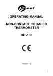
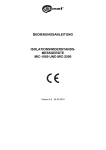
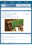
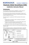
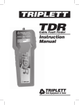
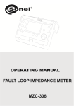
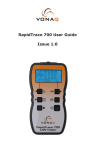
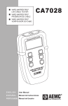
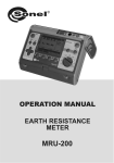
OPERATING MANUAL
TDR-410
TDR CABLE FAULT LOCATOR
SONEL S. A.
Wokulskiego 11
58-100 Świdnica
Poland
Version 1.01 05.03.2014
TDR-410 OPERATING MANUAL
version 1.01
1
We appreciate your having purchased our measuring instrument. TDR-410 is a modern measuring
device, which is easy and safe to use. Please acquaint yourself with the present manual in order to
avoid measuring errors and prevent possible problems related to operation of the meter.
2
TDR-410 OPERATING MANUAL
version 1.01
TABLE OF CONTENTS
1
INTRODUCTION ....................................................................................................5
2
WORKING PRINCIPLES ......................................................................................6
3
PREPARING THE TDR-410 FOR USE ................................................................6
3.1
3.2
3.3
3.4
3.5
3.6
4
SET UNIT OF MEASURE FROM MENU DISPLAY..........................................................7
SET AUTO SHUTDOWN FROM MENU DISPLAY ...........................................................7
SET CONTRAST FROM MENU DISPLAY ......................................................................8
BACKLIGHT............................................................................................................8
SET VELOCITY OF PROPAGATION FROM MENU DISPLAY ...........................................8
HOW TO DETERMINE VP SETTINGS ..........................................................................8
USING THE TDR-410 .............................................................................................9
4.1
SETTING THE FAULT LOCATION ...............................................................................9
4.1.1
Setting Velocity of Propagation (Vp)...........................................................10
4.1.2
Value Impedance Setting (Z) .......................................................................10
4.1.3
Auto Fault Location and Manual Fault Location........................................10
4.1.4
Selecting range scales..................................................................................11
4.1.5
Gain settings ................................................................................................11
5
CONNECTING TDR-410 TO A CABLE TO BE TESTED ...............................11
6
CABLE FAULT LOCATION ...............................................................................12
6.1
6.2
SCAN HOLD AND CONTINUOUS SCANNING MODES ................................................13
ACCURACY...........................................................................................................13
7
TONE GENERATOR ............................................................................................13
8
POWER SUPPLY ..................................................................................................14
9
CLEANING AND MAINTENANCE....................................................................14
10
STORAGE ..............................................................................................................14
11
DISMANTLING AND UTILIZATION................................................................14
12
TYPICAL FAULT DISPLAYS .............................................................................15
13
TYPICAL CABLE VP AND IMPEDANCE VALUES ........................................16
14
TECHNICAL DATA..............................................................................................18
TDR-410 OPERATING MANUAL
version 1.01
3
15
ACCESSORIES ..................................................................................................... 19
16
MANUFACTURER............................................................................................... 19
4
TDR-410 OPERATING MANUAL
version 1.01
1 Introduction
A time-domain reflectometer (TDR) is an electronic instrument used to characterize and locate faults
in metallic cables.
The TDR-410 is a hand held Time Domain Reflectometer with 11-range-scale covering the range 04000 meters, with a 7 meter first range scale and a 0.5 meter dead zone close and far faults are
clearly displayed on its 128x64 pixel back light LiquidCrystalDisplay.
The Auto Fault Location key will move the cursor directly to the first event or fault, thus it eliminates
the need to interpret visiually the form of wave. When set in manual mode, the wave form may be
scanned visually as on conventional TDRs. In both modes the user gains variably coverage of the
range of default to 64 db's used to magnify small events identified on the waveform. The scan lock
feature will allow the user to hold the trace for closer examination.
Designed for identifying and locating faults on all metallic cables with two or more insulated conductors. The TDR-410 has impedance matched circuits for 25, 50, 75 and 100 ohms and with velocity of
propagation settings from 1-99% (or the equivalent in feet ormeters/micro second) will cover the
range of power, data, communication and CCTV cables.
Housed in a rugged IP54 rated ABS enclosure and weighs only 350 grams (12 ounces), theTDR-410
is suitable for outside use.
NOTE!
Only standard and additional accessories for a given device should be used, as listed
in the "Equipment" section. Use of different accessories can lead to errors in the test
connection and can introduce additional measurement uncertainties.
Note:
Due to continuous development of the meter’s software, the actual appearance of the
display, in case of some of the functions, may slightly differ from the display presented
in this operating manual.
Warning:
This instrument meets the safety requirements of IEC61010-1: 1995
TheTX2003 is designed for use on de-energized circuits only.
Connection to line voltages will damage the instrument and could be
hazardous to the operator.
This instrument is protected against connection to telecom network voltages
according to EN61326-1.
Safety is the responsibility of the operator
TDR-410 OPERATING MANUAL
version 1.01
5
2 Working principles
TDR-410 measures the time course of the signal (the probe pulse) in a pair from connecting the cable
to the cable end or the nearest damage and back.
Probe pulses in the cable run at a speed Vp (the speed of propagation), which depends on the electrical parameters of the cable, in particular the material from which the insulation is made.
A reflectometer calculates the distance to the disturbance of wave impedance path and displays the
cable's diagram showing any impedance discontinuity in the studied area based on Vp values selected by a user and and measured the course time of the pulse.
Output via2x4mm
safety sockets
LCD display
Cursor left key / decrease
selected value
Cursor right key / increase
selected value
START fault location
/ scan hold (for MFL)
Navigation button
Back light on/off
Escape / Return
Power on / off
3 Preparing the TDR-410 for use
Press button
1.
2.
3.
to power the tester, the following screen will be displayed:
Model.
Software version programmed into tester.
Battery condition indicator (all black battery, fully charged, as charge decreases symbol changes
to white). Battery condition indicator is permanently displayed.
To select a menu display, press the left button
6
as indicated on the TDR-410 front panel:
TDR-410 OPERATING MANUAL
version 1.01
or to select TDR (Trace Display), press the right button
as indicated on the TDR-410 front panel:
Prior to use the following parameters will need to be set:
Vp (velocity of propagation ) – see part 3.5 i 3.6;
Z (impedance) – see part 4.1.2;
dB (gain) – see part 4.1.5.
3.1 Set Unit of Measure from menu display
Press
(SET) to move
Press
or
to unit of measure (feet or meters):
to scroll between feet and meters. Press ESC to store selected setting in memory.
Note: When unit of measure has been selected, this will automatically change the V/2 figure, which
will also be displayed in the selected unit of measure.
3.2 Set Auto Shutdown from menu display
To preserve battery life the TDR-410 is fitted with an auto shutdown feature. Shutdown time is selectable between disabled 1, 2, 3 and 5 minutes.
To change settings press
- Disabled, or
- 1 minute, or
- 2 minutes, or
(SET) to move
to Shutdown, use
TDR-410 OPERATING MANUAL
or
version 1.01
to select setting:
7
- 3 minutes,
then press ESC to store setting to memory.
3.3 Set Contrast from menu display
Press
(SET) to move
to Contrast. Press
contrast, then press ESC to store setting to memory.
to decrease contrast, press
to increase
3.4 Backlight
The LCD display is fitted with an electro-luminescent backlight to enable easy viewing under a variety
of different lighting conditions. The backlight is switched on and off with the key
.
Note: When switched on, the backlight will significantly shorten the battery life!
3.5 Set Velocity of Propagation from menu display
Velocity of propagation (Vp) may be set as % or speed in micro seconds (µs). The unit of measure,
the speed is displayed in (feet or meters), will be determined by the setting selected in section 3.1
Press
(SET) to move to displayed unit, press
to scroll between ”V/2 m/µs” or ”Vp %Vc”.
To change the value of the V/2 (or Vp) factor, go one level down (press SET button
indicator points to the "........ m/µs" (or "Vp = ...%").
) so that the
Pressing the cursor
or
to increase / decrease the value of the Vp.
Press ESC to store selected setting to memory.
Note: Setting the correct Velocity of Propagation value is also possible from Trace Display.
3.6 How to determine Vp Settings
If the TDR-410 is to be used with a cable type for which the Vp is unknown, this must first be determined by the setting selected in section 3.5
1. Take a sample of the cable at least 10m or 30 ft long (as long as possible).
2. Measure the actual length of cable using a rule or tape measure or some other reliable method.
3. Connect the TDR-410 and adjust the Vp setting such that the tester gives a correct reading of the
sample length, (refer to section 4.1 Setting cable parameters).
8
TDR-410 OPERATING MANUAL
version 1.01
Note: After disconnecting the TDR-410 the current parameter settings are stored, including the
recently selected values Vp propagation factor and impedance Z.
This feature of the device is particularly advantageous in situations where multiple tests are performed on the same type of cables.
4 Using the TDR-410
Upon completion of the set up procedures in section 3, press ESC to return to start up display and
), or press START.
select TDR (pressing the cursor
The following screen will be displayed:
1.
2.
3.
4.
5.
6.
7.
8.
9.
10.
Vp setting
Impedance setting (Z)
Manual / Auto Fault Location
Range scale
Battery condition indicator
Scan hold icon
User variable gain (by user or auto)
Cursor distance reading
Cursor
Output pulse
4.1 Setting the fault location
You can set all the necessary parameters of the cable fault location from Trace Display:
•
•
•
•
•
Velocity of Propagation
Impedance value (Z)
Auto or Manual location mode (AFL, MFL)
Range Scale
Gain
To set a parameter, press the SET button (
change the value or the option.
). Until the parameter is highlighted, use
TDR-410 OPERATING MANUAL
version 1.01
or
to
9
Press ESC to store selected setting to the memory of the device.
Note: Current parameter settings are stored after disconnecting the TDR-410
4.1.1 Setting Velocity of Propagation (Vp)
Use SET button (
values.
) to scroll to “Vp=...%”, when parameter is highlighted, use
or
to change
Press SET button (
) to move to next parameter, when set up is completed press ESC to store settings.
If Vp cable is unknown, refer to section 3.6.
TDR-410 will display the values last used after the start up.
4.1.2 Value Impedance Setting (Z)
Use SET button (
values.
) to scroll to “Z=.... Ω”, when parameter is highlighted, use
Press SET button (
tings.
or
to change
) to move to next parameter, when set up is completed press ESC to store set-
4.1.3 Auto Fault Location and Manual Fault Location
The TDR-410 may be used in auto or manual fault location modes. Use SET button (
displayed setting (AFL or MFL) use key
or
) to scroll to
to change setting. Press ESC to store settings.
Auto Fault Location.
When set in auto fault location (AFL) the TDR-410 will scan the cable run and the cursor will automatically stop at the first event. To start the scan press START key, if the scan stops within the first
meter (3 feet) it will identified the connection between the TDR-410 and the cable under test as an
event, press the key START to continue the scan. The end of the cable run would normally be identified as an open or short (refer to section 12 for typical fault displays). Small events identified in the
cable run may be enlarged by increasing the gain thereby making the fault more obvious (refer to
section 4.1.5 Gain Settings).
10
TDR-410 OPERATING MANUAL
version 1.01
Manual Fault Location
When the manual fault location (MFL) is set, the operator selects the range manually and then he
needs to scan the displayed trace, and align the cursor manually to the identified event.
Note: – see chapter 6.1 „Scan hold and continuous scan mode”.
4.1.4 Selecting range scales
The TDR-410 has 11 range scales covering the range of 0 to 4,000 meters (7m, 15m, 30m, 60m,
120m, 250m, 500m, 1000m, 2000m, 3000m and 4000m). To select a range scale, or scan the cable
run, press SET button (
) to scroll to range scale, then press
to increase range. To save and exit press ESC.
to decrease range or press
Note: Manual measurement range change is just for MFL mode.
4.1.5 Gain settings
The TDR-410 has pre set gain for each of its 11 range scales, there is in addition to this a user controllable gain to a maximum of 64 dB in 1 dB steps. To use this function, use navigation key (SET
) to scroll to dB setting, press
to decrease gain,
ting.
Note: The "Def" means the default settings.
to increase gain, press ESC to store set-
5 Connecting TDR-410 to a cable to be tested
Attach the test lead set to the TDR-410 via the 2 safety sockets located at the top of the unit.
1. Ensure that no power supply or equipment is attached to the cable to be tested
2. Ensure that the far end of the cable under test is open or shorted (not fittedwith a resistive termination)
3. Attach theTDR-410 to one end of the cable to be tested
TDR-410 OPERATING MANUAL
version 1.01
11
Coaxial Cable:
Connect the red clip to the centre wire and the black clip to the shield/screen.
Shielded Cable:
Connect the red clip to a wire adjacent to the shield and the black clip to the shield.
Twisted Pair:
Separate out one pair and connect the red and black clips to the two wires of the pair.
MulticoreCable:
Connect the clips to any two wires.
6 Cable Fault Location
Having followed the set up procedures in the preceding sections, a typical display showing impedance anomalies is shown below. Further examples are shown in section 12.
The vertical cursor line is moved left or right along the line of the trace by pressing
or
buttons
to determine the distance to the event. Position the cursor at the beginning of the event and read off
the distance at the bottom left corner.
12
TDR-410 OPERATING MANUAL
version 1.01
Example:
On the fault display shown above a low impedance fault occurs at 64 meters shown by a negative
spike, and a high impedance at 129 meters. The open end of the cable is shown as a large positive
spike, this is used to determine the end of the cable run and the overall length of the cable being 180
meters.
6.1
Scan hold and Continuous Scanning Modes
This function only operates in manual fault location mode. When the TDR-410 is first switched on, it
is set to “Continuous scan”mode. In this mode the TDR-410 fires pulses into the cable under test thus
enabling intermittent faults to be identified. Scan hold allows the user to hold a trace for closer examination and to disconnect from test cable whilst leaving the trace displayed.
To select / unselect scan hold, press key START (HOLD) for approximately 1 second then release,
scan hold icon is displayed at the bottom right hand corner (
6.2
).
Accuracy
The TDR-410 is able to measure distances to faults and cable lengths to an accuracy of +/- 1%.
This measurement accuracy is based on the correct value of Vp being used for the cable under test,
and homogeneity of the Vp along the cable length.
If the Vp is set incorrectly by the operator, or the Vp varies along the length of the cable, then additional errors will be incurred and the measurement accuracywill be affected.
Note: The Vp is less well defined with unshielded multicore cable, including power cable, and is lower
when a cable is tightly wound on a drum than when installed.
7 Tone Generator
The TDR-410 may also be used as a tone generator to trace and identify cables and wires. The user
will need a conventional inductive tone probe within the range 810Hz to 1110Hz.
To select tone generator from menu display, press SET
to move
to TDR. Press
to
scross between TDR and warble. Press the ESC button to exit.. “Warble Tone” on screen mesage is
displayed after pressing ESC and TDR generate the tone. TDR mode is switched back if ESC is
pressed once again.
TDR-410 OPERATING MANUAL
version 1.01
13
Note: The auto off function is disabled in tone generator mode so that the tone can be injected into a
cable for extended periods while tracing takes place.
8 Power supply
Reflectometer TDR-410 is powered by four 1.5 V AA batteries. Use alkaline batteries to ensure
proper functioning of the device,. Low battery is signaled by the appearance of the symbol on the
screen of the reflectometer.
To replace the batteries:
- disconnect the instrument from any cable or network link,
- turn the instrument off,
- loosen the two black screws and remove the battery compartment cover,
- replace the batteries with 4 x 1.5 volt Alkaline batteries, observing the polarities
- refit the battery compartment cover and refit the two screws
9 Cleaning and maintenance
NOTE!
Apply solely the maintenance methods specified by the manufacturer
in this manual.
The casing of the meter may be cleaned with a soft, damp cloth using all-purpose detergents. Do not
use any solvents or cleaning agents which might scratch the casing (powders, pastes, etc.).
The electronic system of the meter does not require maintenance.
10 Storage
In the case of storage of the device, the following recommendations must be observed:
• Disconnect all the test leads from the meter.
• Clean the meter and all its accessories thoroughly.
• In the case the meter is to be stored for a prolonged period of time, the batteries must be removed
from the device.
11 Dismantling and utilization
Worn-out electric and electronic equipment should be gathered selectively, i.e. it must not be placed
with waste of another kind.
14
TDR-410 OPERATING MANUAL
version 1.01
Worn-out electronic equipment should be sent to a collection point in accordance with the law of
worn-out electric and electronic equipment.
Before the equipment is sent to a collection point, do not dismantle any elements.
Observe the local regulations concerning disposal of packages, worn-out batteries and accumulators.
12 Typical Fault Displays
The following diagrams show typical fault traces to assist you in the identification of faults using the
TDR-410:
TDR-410 OPERATING MANUAL
version 1.01
15
13 Typical Cable VP and Impedance Values
Cable type
Insulation type
VP
Electricity
paper saturated with oil
Cross-linked Polyethylene
paraffin
polyethylene
PTFE
paper
polyethylene foam
air
0,50 - 0,56
0,52 - 0,58
0,64
0,67
0,71
0,72 - 0,88
0,82
0,94 - 0,98
Phone
polyethylene outer diameter 0.912 mm
polyethylene outer diameter 0.643 mm
polyethylene outer diameter 0,511 mm
polyethylene outer diameter 0.404 mm
gel, outer diameter 0.912 mm
gel, outer diameter 0.643 mm
gel, outer diameter 0,511 mm
gel, outer diameter 0.404 mm
paper outer diameter 0,643 m
paper outer diameter 0,511 mm
paper outer diameter 0.404 mm
0,69
0,68
0,66
0,65
0,68
0,65
0,64
0,63
0,69
0,68
0,66
CCTV
QR PARA III
PARA I
T, TR
TX, TX10
RG6, RG11, RG59
Times Fiber RG-59
Dynafoam
0,88
0,82
0,87
0,89
0,82
0,93
0,90
Data transmission
RG58
RG58U
UTP 26
Thinnet
Ethernet
Token Ring
Twinaxial Air
Twinaxial
Thicknet
RG58
RG58/U
Twisted Pair
U/UTP cat. 5e
U/UTP cat. 6
0,78
0,76
0,64
0,66 – 0,70
0,77
0,78
0,80
0,71
0,77
0,78
0,66
0,64 – 0,66
0,67
0,67
Note: TDR-410 measures the distance to a fault in a cable or the cable length with an accuracy
specified in the technical specifications. The current accuracy of the measurement depends on:
- how the the propagation factor VP was determined,
- its stability on the whole lenght of the tested cable.
16
TDR-410 OPERATING MANUAL
version 1.01
The measurement has an additional fault if:
- you set an incorrect value of VP,
- this ratio is not constant over the measured distance.
Please note that the value of the VP factor is smaller for cable wound on the drum's than cable
uncoiled / unwound and installed. Furthermore, it may also change with the cable aging.
The above examples of VP factor for different cable types are only an indication for the user
to make swift and calculate the measurement with reasonable accuracy
The use of VP allows the highest measurement accuracy calculated by the user with a known
length of the tested cable section, as described in detail in section 3.6.
Typical values of impedance Z
Cable type
Cat 5 STP
Cat 5 UTP
Coaxial air
Coaxial drive
Coaxial PE foam
Coaxial full PE
Symmetrical PE gel
Symmetrical dry PE
Symmetrical PTFE
Symmetrical PVC
Paper 72nF
Paper 83nF
TDR-410 OPERATING MANUAL
Z
100
100
50/75
50/75
50/75
50/75
100
100
100
100
100
100
version 1.01
17
14 Technical data
Ranges Meters:
7, 15, 30, 60, 120, 250, 500, 1km, 2km, 3km, 4km
Ranges Feet
20, 45, 90, 180, 360, 750, 1500, 3000, 6000, 10000, 14000.
Range Selection
Manual range control / Auto range
Accuracy
1% of selected range*
Resolution
Approx 1% of range
Minimum cable lenght:
4m (14ft)
Sensitivity
Min 3 pixel return at 4km on 0.6mm Ø, PE, TP
Velocity Factor
Adjustable from 1% to 99%
Output Pulse
5 volts peak to peak into open circuit
Output Impedance
Selectable 25, 50, 75 & 100 Ω
Output Pulse
Width 3 ns to 3 µs, Automatic with range
Scan Rate
2 scans/second or scan held, pre set for each range scale
Tone Generator
810 – 1100Hz
Battery Life
30 hours continuous scanning
Power Supply
6 volts 4 x 1.5 AA Alkaline cells, on-screen low voltage indicator
Power Down Selectable
1, 2, 3, 5 minutes or disabled
Back Lit Display
128 x 64 pixel
Operating Temp
-10º / 50ºC
Storage Temp
-20º +70° C
Dimensions
165 x 90 x 37 mm (6.5 x 3.5 x 1.5 ins)
Weight
350 g (12oz)
EMC
BS/EN 61326-1
Water/Dust Proof
IP54
Symbol complies with the current EU directives
* Measurement accuracy of <+/- 1% assumes the instrument setting for velocity of propagation (Vp)
of the cable under test to be accurately set, homogeneity of the Vp along the cable length, and accurate cursor positioning.
18
TDR-410 OPERATING MANUAL
version 1.01
15 Accessories
The standard set provided by the manufacturer includes the following components:
• Time-domain reflektometer TDR-410 WMGBTDR410
• 0,6 m double-wire lead WAPRZ0X6DZBB,
• red crocodile clip WAKRORE20K02,
• black crocodile clip WAKROBL20K01,
• cover M-2 WAFUTM2,
• alkaline batteries 1.5V AA (4 pieces),
• user manual.
It is possible to additionally purchase from the manufacturer and distributors the following elements,
which are not included within the standard accessories:
• voltage separator AS-2 WAADAAS2.
16 Manufacturer
The manufacturer of the device, which also provides guarantee and post-guarantee service is the following company:
SONEL S. A.
Wokulskiego 11
58-100 Świdnica
POLAND
(+48 74) 858 38 60
fax (+48 74) 858 38 09
e-mail: [email protected]
Homepage: www.sonel.pl
Attention:
Service repairs must be realised solely by the manufacturer.
Made in UE.
TDR-410 OPERATING MANUAL
version 1.01
19
NOTES
20
TDR-410 OPERATING MANUAL
version 1.01