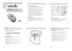
1
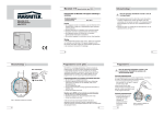
Marmitek X-10 Fasekoppelaar FKX40
Installatie/montage
Functie
!
De fase-koppelaar koppelt Marmitek X-10 commando's, die via
de ene fase binnenkomen, door op de andere twee fasen.
Daarbij worden de Marmitek X-10 commando's versterkt op alle
fasen verzonden.
Marmitek X-10
Fasekoppelaar/Repeater
type FKX40
PROGRAM
STATUS 1
STATUS 1
STATUS 1
RECEIVE 1
RECEIVE 2
Phase Coupler/Repeater
FKX40
RECEIVE 3
L1
L2
L3
Pas op! Eerst de spanning
uitschakelen voordat u met
de montage begint.
De FKX40 Fasekoppelaar/ Repeater is
een DIN rail module en dient in een
groepenkast te worden gemonteerd.
N
Montage
L1
L2
L3
N
De fase-koppelaar dient op de
afgaande zijde van een 3-fasen
installatieautomaat (3p+N) met een
maximale nominaalstroom van 16 A
te worden aangesloten (zie figuur 1).
PROGRAM
Let op! De klemmen van de
FKX40 zijn niet geschikt om
als aftakpunt naar andere groepen
of belastingen te gebruiken. Het aansluiten anders dan weergegeven in
figuur 1 is derhalve niet toegestaan.
!
STATUS 1
STATUS 1
STATUS 1
RECEIVE 1
RECEIVE 2
RECEIVE 3
L1
L2
Phase Coupler/Repeater
FKX40
L3
N
Figuur 1.
2
In bedrijf nemen
!
Programmeren
Pas op! Vermijdt het aanraken van stroomvoerende
delen. Sluit de groepenkast alvorens de spanning in
te schakelen.
Zodra de spanning weer wordt ingeschakeld zal de gele LED (bij
program) eens in de drie seconden oplichten (zie figuur 2).
LED
Program (geel)
Status (groen)
Receive (rood)
3
Functie van de LED's
Knippert eens in de 3 seconden.
Knippert per verzonden data pakket op deze fase.
Knippert per ontvangen data pakket op deze fase.
Programmeren
Standaard instellingen
Wijzigen van de instellingen van de FKX40
De fasekoppelaar zal standaard, vanuit de fabrieksinstellingen,
automatisch de Marmitek X-10 commando's van de ene fase
doorkoppelen naar de overige fasen. Hierbij zullen de signalen
met het maximale zendniveau (versterkt) op alle fasen worden
verstuurd. In de meeste gevallen zal de fasekoppelaar in de
standaard instelling het best functioneren. Onder bepaalde
specifieke omstandigheden kan het echter nodig zijn de
instelling te wijzigen.
Slechts onder bepaalde omstandigheden kan het noodzakelijk
zijn om de instellingen van de fasekoppelaar te veranderen.
De volgende programmeer instellingen zijn mogelijk:
!
Standaard
Repeater
Fase 1 AAN*)
Repeater
Fase 1 UIT
Let op! Wij adviseren u om de instellingen van de
fasekoppelaar bij twijfel niet te wijzigen.
Repeater
Fase 2 AAN*)
Repeater
Fase 2 UIT
PROGRAM
PROGRAM
Repeater
Fase 3 AAN*)
STATUS 1
STATUS 1
STATUS
Repeater
Fase 3 UIT
STATUS 1
RECEIVE 1
RECEIVE 2
RECEIVE 3
L1
L2
Phase Coupler/Repeater
FKX40
L3
Koppelaar
functie AAN*)
N
Koppelaar
functie UIT
Figuur 2.
4
Optioneel
5
6
Setup
Commando's
LED
Indicatie
2 x ABright
Status LED 1: AAN
2 x ADim
Status LED 1: UIT
2 x BBright
Status LED 2: AAN
2 x BDim
Status LED 2: UIT
2 x CBright
Status LED 3: AAN
2 x CDim
Status LED 3: UIT
2 x ON
Receive LED 1: AAN
2 x OFF
Receive LED 1: UIT
Programmeren
Standaard
Optioneel
Default *)
Reset
to default
Setup
Commando's
--2x
All Lights On
LED
Indicatie
Receive LED 3: UIT **)
LED's en instellingen
naar fabrieksinstellingen
*) Standaard fabrieksinstelling.
**) In de programmeer mode zal de "Receive LED 3" knipperen gedurende 0,5 s als er
Setup Commando's ontvangen worden.
Beschrijving van de opties:
Repeater Fase 1 UIT: Ontvangen Marmitek X-10 commando’s
zullen niet versterkt worden op deze fase.
Repeater Fase 2 UIT: Ontvangen Marmitek X-10 commando’s
zullen niet versterkt worden op deze fase.
Repeater Fase 3 UIT: Ontvangen Marmitek X-10 commando’s
zullen niet versterkt worden op deze fase.
Koppelaar functie UIT: Ontvangen Marmitek X-10 commando’s
zullen niet naar andere fases doorgekoppeld
worden. Deze optie kan worden toegepast
in test-situaties.
Reset naar fabrieks- Alle opties zullen terug worden gezet naar
instellingen:
de fabrieksinstellingen.
7
Troubleshooting
Stap 2:
Stap 3:
Zet de FKX40 in de programmeer modus en stel de optie in:
"Koppelaar functie Uit" (Receive LED 1: OFF). Verlaat de
programmeer modus en controleer of dit het probleem oplost.
Zet de FKX40 weer in de programmeer modus en stel de optie
in: "Koppelaar functie AAN" (Receive LED 1: AAN). Als dit het
probleem niet oplost, ga dan naar de volgende stap.
Controleer de fase die overeenkomt met de knipperende LED op
eventuele storingen van componenten of apparatuur.
Troubleshooting
Activeren van de programmeer modus:
De FKX40 dient als volgt in de programmeer modus te worden
gezet:
• Druk minimaal 3 seconden
op de programmeerknop
(zie figuur 3) totdat de gele
LED gaat branden. De
Status/Recieve LED's
geven nu de geactiveerde
opties weer.
L1
L2
L3
N
• Verstuur de setupcommando's behorende bij
de gewenste instelling(en)
door middel van een
PMIX35 over het lichtnet
naar de FKX40.
PROGRAM
Constatering: Alle LED's zijn uit. De gele "Program" LED knippert niet
STATUS 1
STATUS 1
STATUS 1
RECEIVE 1
RECEIVE 2
RECEIVE 3
Phase Coupler/Repeater
FKX40
Checklist:
eens per 3 seconden.
Controleer of er spanning aanwezig is en controleer het
voedingscircuit van de krachtautomaat naar de FKX40.
Constatering: De Status LED en de Receive LED voor de zelfde fase
Checklist:
branden constant.
Controleer de voedingsaansluiting voor deze fase op de FKX40.
Constatering: Eén of meer Receive en Status LED's knipperen constant.
Figuur 3.
Stap 1:
Opheffen van de programmeer modus:
• Druk kort op de programmeerknop of wacht 60 seconden
zodat de programmeerfunctie automatisch wordt opgeheven.
Zet de FKX40 in de programmeer modus en controleer of
Receive LED 2 brandt. Zo ja, verstuur het commando "Status On"
2 x over het lichtnet d.m.v. een PMIX35 om de onderliggende
functie te deactiveren. Receive LED 2 moet uitgaan. Verlaat de
programmeer modus. Als dit het probleem niet oplost, ga dan
naar de volgende stap.
8
9
Technische gegevens
Ongestoorde werking van het Marmitek X-10 systeem
Elektronische apparaten en systemen kunnen gevoelig zijn voor
signalen van andere apparaten, die elektromagnetische storing
veroorzaken. Binnen de Europese Unie zijn afspraken gemaakt over
de immuniteit (gevoeligheid) van de apparatuur voor signalen en
ook de emissie (storing) van deze apparatuur. Als de apparaten/
toepassingen in een omgeving voldoen aan de daarvoor geldende
normen, zullen ze elkaar niet storen (ze zijn dan "Elektro Magnetisch
Compatibel").
Voor residentiële omgevingen, waar het huisautomatiseringssysteem Marmitek X-10 wordt toegepast, is de Europese norm
voor immuniteit vastgelegd in de EN 61000-6-1. Apparatuur die
voldoet aan deze norm is bestand tegen de elektromagnetische
emissie van overige apparaten die voldoen aan de Europese norm
EN 61000-6-3 (residentiële omgevingen). Ervaring heeft geleerd dat
in woonhuizen apparatuur kan voorkomen dat een EMC-emissieniveau heeft boven de in EN 61000-6-3 vastgestelde niveaus. Deze
apparatuur kan de correcte werking van de Marmitek X-10 modules
verstoren. De immuniteit van de Marmitek X-10 inbouwmodules is
om die reden opgewaardeerd en gelijkwaardig geworden aan de
EN 61000-6-2, de strengere Europese norm voor immuniteit in
industriële omgevingen.
Marmitek X-10 huisautomatisering
Nominale spanning
3-fase, 230 Vac, 50 Hz
Totaal stroomverbruik
<2W
Signaal transmissie
> 5 Vpp in 5 Ω bij 120 kHz volgens
EN 50065-1, EN 50065-2-1, EN 50065-4-1
Transmissie synchronisatie 1 puls burst op 0°/180°
Signaal gevoeligheid
25 mVpp…6 Vpp bij 120 kHz ± 4 kHz
Signaal/ruis verhouding
1,35 : 1
Aansluitbereik
2,5 mm2 massief
Min. omgevingstemperatuur 0 °C
Max. omgevingstemperatuur 40 °C
Atmosferische druk
86 pkA - 106 pkA
Relatieve luchtvochtigheid
(non condensing)
30 tot 90%
Beschermingsgraad
Behuizing:
IP40 volgens IEC 60 529
Aansluitcontact: IP20 volgens IEC 60 529
Kleur
RAL 7035
Normen
NEN-EN-IEC 60669-2-1, NEN-EN-IEC 60669-2-2
Behuizing voldoet aan de IEC 60707: BH 2-30,
UL94: V-0
Markering
Technische wijzingen voorbehouden.
10
In de programmeer modus is de gele LED "Program" AAN en
geven de Status/Receive LED's de geactiveerde opties weer.
Hierdoor kan de programmeer modus ook gebruikt worden om
de instellingen van de fasekoppelaar te bekijken.
11
Desalniettemin dient het toepassinggebied van Marmitek
X-10 beperkt te blijven tot residentiële omgevingen.
12
Afmetingen
Marmitek is niet verantwoordelijk voor het disfunctioneren
van het Marmitek X-10 systeem als gevolg van in het gebouw
aanwezige apparatuur met emissiewaardes boven de
maximale toegestane niveaus zoals die gelden in residentiële,
commerciële en lichtindustriële omgevingen en zijn
vastgelegd in de EN 61000-6-3.
Residentieel
Commercieel
Licht-industrieel
Geldende Europese norm
Marmitek X-10 huis
automatisering*
Immuniteit van
de apparatuur
61000-6-1
Immuniteit- en
emissienorm
Compatibel/
voldoet
Emissie van
de apparatuur
61000-6-3
L1
* Voorwaarde daarbij is dat het gehele Marmitek X-10 systeem wordt
geïnstalleerd volgens de geldende instructies door een gecertificeerde en
getrainde Marmitek X-10 dealer.
58
Marmitek X-10
Phase Coupler/Repeater
type FKX40
89,5
Toepassing
72
L2
L3
N
PROGRAM
Copyrights
Marmitek is a trademark of Pattitude B.V., FKX40™ is a trademark of Marmitek B.V. All rights reserved.
Copyright and all other proprietary rights in the content (including but not limited to model numbers, software,
audio, video, text and photographs) rests with Marmitek B.V. Any use of the Content, but without limitation,
distribution, reproduction, modification, display or transmission without the prior written consent of Marmitek is
strictly prohibited. All copyright and other proprietary notices shall be retained on all reproductions.
STATUS 1
STATUS 1
STATUS 1
RECEIVE 1
RECEIVE 2
RECEIVE 3
L1
13
Marmitek X-10 FKX40 Phase Coupler
L3
N
20315 - 20100929
Installation/assembly
Role
The phase coupler transmits Marmitek X-10 commands that
enter from one phase to the other two phases. These
commands are repeated when transmitted to all phases.
L2
Phase Coupler/Repeater
FKX40
!
PROGRAM
STATUS 1
STATUS 1
STATUS 1
RECEIVE 1
RECEIVE 2
Phase Coupler/Repeater
FKX40
RECEIVE 3
L1
L2
L3
Commissioning
Proceed with care!
Switch off the power before
starting assembly.
The FKX40 Phase Coupler/Repeater is
a DIN rail module and must be
installed in a distribution box.
N
Assembly
The phase coupler must be connected
to the load end of a 3-phase miniature
circuit breaker (3p+N) with a maximum
rated current of 16 A (see Figure 1).
L1
L2
L3
!
Proceed with care!
Avoid touching live parts. Close the distribution
box before switching on the voltage.
As soon as the power is switched on again, the yellow LED
(Program) will blink once every three seconds (see Figure 2).
LED
Program (yellow)
Status (green)
Receive (red)
Function of the LEDs
Blinks every three seconds.
Blinks on every transmitted data package for this phase.
Blinks on every received data package for this phase.
N
PROGRAM
Please note:
The FKX40 terminals are not
suitable for use as branching points
to other groups or loads.
Connections are, therefore, only
permitted as indicated in Figure 1.
!
PROGRAM
STATUS 1
STATUS 1
STATUS
STATUS 1
RECEIVE 1
RECEIVE 2
RECEIVE 3
L1
Figure 2.
Figure 1.
16
17
18
L2
Phase Coupler/Repeater
FKX40
L3
N
Programming
Programming
Standard settings
Changing the FKX40 settings
Standard
The phase coupler/repeater will automatically, from its factory
settings, transfer and repeat Marmitek X-10 commands from
one phase to the other. The signals are transmitted (repeated) to
all phases at the maximum transmission level. In general, the
phase coupler will operate best in the standard setting.
However, under special circumstances it may be necessary to
change the settings.
Only in certain circumstances is it necessary to change the
settings of the phase coupler.
The following programming options are available:
Default *)
!
Please note:
We recommend that, if in doubt, you do not change
the phase coupler's settings.
Standard
Optional
Setup
Commands
LED
Indication
2 x ABright
Status LED 1: ON
2 x ADim
Status LED 1: OFF
2 x BBright
Status LED 2: ON
2 x BDim
Status LED 2: OFF
2 x CBright
Status LED 3: ON
2 x CDim
Status LED 3: OFF
2 x ON
Receive LED 1: ON
Coupler
2 x OFF
Function OFF
Receive LED 1: OFF
Repeater
Phase 1 ON*)
Repeater
Phase 1 OFF
Repeater
Phase 2 ON*)
Repeater
Phase 2 OFF
Repeater
Phase 3 ON *)
Repeater
Phase 3 OFF
Coupler
Function ON*)
19
Programming
The FKX40 must be set to the programming mode as follows:
• Press the program button
for at least three seconds
(see Figure 3) until the
yellow LED lights up. The
Status/Receive LEDs now
display the activated
options.
• Send the set-up commands
L1
L2
L3
N
that correspond to the
desired setting(s) over the
power line to the FKX40
via a PMIX35.
Repeater Phase 1 OFF:
Received Marmitek X-10 commands
will not be repeated on this phase.
Repeater Phase 2 OFF:
Received Marmitek X-10 commands
will not be repeated on this phase.
Repeater Phase 3 OFF:
Received Marmitek X-10 commands
will not be repeated on this phase.
Coupler function OFF:
Received Marmitek X-10 commands
will not be repeated to other phases.
This option can be used in test
situations.
Reset to factory settings: All options will be reset to the factory
settings.
21
Troubleshooting
In programming mode the yellow LED "Program" is ON and the
Status/Receive LEDs indicate the activated options. The
programming mode can therefore also be used to check the
phase coupler's settings.
Step 2:
Observation: All LEDs are off. The yellow "Program" LED does not
Step 3:
STATUS 1
STATUS 1
RECEIVE 3
Phase Coupler/Repeater
FKX40
Checklist:
blink every three seconds.
Check whether there is any voltage and check the feeder circuit
of the circuit breaker to the FKX40.
Observation: The Status LED and the Receive LED for the same phase
Checklist:
are on constantly.
Check the power connection for this phase on the FKX40.
Observation: One or more Receive and Status LEDs are blinking
Figuur 3.
Step 1:
Deactivating the programming mode:
• Briefly press the program button or wait 60 seconds so that
the programming function deactivates automatically.
22
2x
All Lights On
20
STATUS 1
RECEIVE 2
Reset
to default
LED
Indication
Receive LED 3: OFF **)
LEDs and settings
according to factory
settings
Option description:
PROGRAM
RECEIVE 1
Setup
Commands
---
*) Default factory setting.
**) In programming mode "Receive LED 3" will blink for 0.5 s when set-up commands
are being received.
Troubleshooting
Activating the programming mode:
Optional
constantly.
Set the FKX40 to programming mode and check whether Receive
LED 2 is on. If it is on, send the "Status ON" command twice over
the power line via a PMIX35 to deactivate the underlying
function. Receive LED 2 should go off. Exit the programming
mode. If this does not solve the problem, go to the next step.
23
24
Set the FKX40 to programming mode and set option "Coupler
function OFF" (Receive LED 1: OFF). Exit the programming mode
and check whether this solves the problem.
Reset the FKX40 to programming mode and set option "Coupler
function ON" (Receive LED 1: ON). If this does not solve the
problem, go to the next step.
Check the phase that corresponds to the blinking LED for any
component or equipment faults.
Technical data
Undisturbed functioning of Marmitek X-10 automation
Marmitek X-10 home automation
Rated Voltage
3-phase, 230 VAC, 50 Hz
Total power consumption
<2W
Signal transmission
> 5 Vpp in 5 Ω at 120 kHz in accordance with
EN 50065-1, EN 50065-2-1, EN 50065-4-1
Transmission synchronization
1 pulse burst at 0°/180°
Signal sensitivity
25 mVpp…6 Vpp at 120 kHz ± 4 kHz
Signal/noise ratio
1.35 : 1
Connection range
2.5 mm2 solid
Minimum ambient temperature 0 °C
Maximum ambient temperature 40 °C
Atmospheric pressure
86 pkA - 106 pkA
Relative humidity
(non condensing)
30 - 90%
Degree of protection
Housing: IP40 according to IEC 60 529
Terminal contact: IP20 according to IEC 60 529
Colour
RAL 7035
Standards
NEN-EN-IEC 60669-2-1, NEN-EN-IEC 60669-2-2
Housing complies with IEC 60707:
BH 2-30, UL94: V-0
Marking
Subject to technical changes without prior notice.
25
Electrical equipment and systems can be sensitive to signals from
other equipment, which causes electro magnetic disturbance. In
the European Union, countries agreed upon laws for the immunity
(sensitivity) of signals of other equipment as well as equipment
emission (disturbance). When equipment or applications in a certain
surrounding comply with the valid standards, they will not disturb
each other's operations (they are called "Electro Magnetic
Compatible").
For residential surroundings, where the home automation system
Marmitek X-10 is being applied, the European standard for
immunity is standardised in EN 61000-6-1. Equipment that complies
with this standard is resistant to electro magnetic emission of other
equipment, which complies with the European standard EN 610006-3 for residential surroundings. Experience has shown that in
domestic surroundings, equipment is being used which has an
EMC-emission level that is above the levels stated in EN 61000-6-3.
This equipment can disturb the correct functioning of the Marmitek
X-10 modules. The immunity of the Marmitek X-10 built-in modules
is therefore revaluated and equivalent to EN 61000-6-2 (the more
severe European standard for immunity in industrial surroundings).
Marmitek is therefore not responsible for the disfunctioning
of the Marmitek X-10 system as a consequence of equipment
in the building with emission levels that exceed the maximum
allowed levels set as standard for residential, commercial and
semi-industrial surroundings stated in EN 61000-6-3.
Application area
Residential
Commercial
Semi-industrial
Valid European Standard
Marmitek X-10
home automation*
Immunity of
equipment
Emission of
equipment
Immunity and
emission standards
61000-6-1
61000-6-3
Compatible/
meets the
requirements
* Condition is that the total Marmitek X-10 system is installed in accordance
with valid instructions supplied by a certified and trained Marmitek X-10
dealer.
Nevertheless, the application area for Marmitek X-10 will
remain restricted to residential areas.
26
27
Dimensions
58
Copyrights
Marmitek is a trademark of Pattitude B.V., FKX40™ is a trademark of
Marmitek B.V. All rights reserved. Copyright and all other proprietary
rights in the content (including but not limited to model numbers, software, audio, video, text and photographs) rests with Marmitek B.V. Any
use of the Content, but without limitation, distribution, reproduction,
modification, display or transmission without the prior written consent of
Marmitek is strictly prohibited. All copyright and other proprietary notices
shall be retained on all reproductions.
89,5
72
L1
L2
L3
N
20320 - 20100929