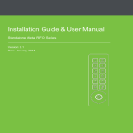
Transcript
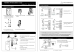
Installation / User Manual
(M-F100, Rev: 1.0)
I.Installation
Method two: 86 type bottom box
Method one: on the wall
Step 1, remove the screws
from the bottom of the
device by screwdriver
Step 2, remove the hanging panel
from the device
Step 1, remove the screws from
the bottom of the device by
screwdriver
Step 5, fix the device to the
back cover properly
Step 4,the equipment installed
in 86 boxes have been fixed rear
panel on the wall
steps 5, the device fixed rear
panel
II.Diagram of system
installation
III.
Step 4, install the device on the
fixed back cover
Step 3, install the device on
back cover of the fixed 86 type
bottom box on wall
-3-
☆Set main switch for alarm (default: open)
This equipment is main switch of alarm function, when it’s ON, wrong pressing alarm,
tamper alarm, door magnetic alarm can send alarm normally. After switch to OFF, can
not send any alarm.
△Attention: When ID 00001 is empty(no used yet), could proceed cards registration
by batch. After registration operating, previous all users will be deleted.
△
! Caution: once touch the alarm, the buzzer of the device alarm first, after
&Note: After device is set up standby mode and enter to this mode, LED,
key light, fingerprint light are all off. This mode default to closed.
☆Set delay for door magnetic (default : 5 seconds)
Delay for door magnetic is delay to exam the door magnetic after the door
opened. After door is opened, device will exam the door magnetic auto., the
device will alarm if the magnetic status does not match door magnetic mode.
2.5 Set door magnetic mode (Default: no )
Door magnetic modes are normal open, normal closed, no door magnetic.
normal open is door magnetic keep opening. normal closed is door magnetic
keep closed. no door magnetic is device does not detect door magnetic.
&Note: Details explanation for the validation mode as follows.
!
Validation mode
☆Set wrong pressing for alarm (default: open)
When set “open”, will send out alarm signal when validate failed 3 times
and can not proceed manager’s validation within 20 seconds.
Mode
Explanation
Mode one (key [ 1 ] )
PW
For password validation only
Mode one (key [ 2 ] )
RF
For card validation only
Mode one (key [ 3 ] )
FP
For fingerprint validation only
Mode one (key [ 4 ] )
FP/PW/RF
For fingerprint, or password, or card validation
Mode one (key [ 5 ] )
RF & PW
For card and fingerprint validation(no sequence)
Mode one (key [ 1 ] )
FP & PW
For fingerprint and password validation(no sequence)
2.4 Set standby mode (default : closed)
&Note: When input door magnetic delay time, device will auto.confirm if 3
digits, need press # to confirm if less than 3 digits. Invalid when input larger
than 254.
&Note : the set door magnetic mode is the basis for door magnetic alarm.
-16-
-15-
You can edit mode by power on, all lights and validation modes are closed
when enter to standby. You can activate by press any one key except for
door bell button.
-14-
& Note:
1. When use “ 0 “ for new password setup after entering one group
for changing password, this new password will be closed and this new
password could not be used for door opening.
2. After revising one group password successfully, input next group
number which need to be revised as well, device will enter next group
directly for revising password.
☆How to delete all users
Note: the situation of device and electrical lock share the same power
supply are 1>. UnLock=12V; 2>. 1-Lock>1; 3>. Short distance between device
and electrical lock.
B.
Device does not share same power supply with electrical lock
Note:
The situation that device does not share the same power supply with
electrical lock are
1>. ULock=12V and 1-Lock 01A;
2>. UlockK12V;
3>. Long distance between device and electrical lock.
“1” defaulted as the output electricity from device, UnLock defaulted as
the working voltage of the electrical lock; 1Lock defaulted as the working
current of the electrical lock.
V.
Connecting to power supply
Note: the device only could be connected the alarm with output less
than and equal to DC12V.
-7-
-6-
& Note: Manager’s initial password is 123456 and has total 3 groups.
After user validates those initial passwords, all the passwords
must be revised immediately.
☆How to revise manger’s initial password
& Note:
1. When register a new user, ID number will auto. Increase. After register successfully,
will skip to another new registration.
2. If the quality of the fingerprint is bad, the fingerprint and card registration are failed.
After setup flash the green light, you can register again.(the registered information
need not to be logged in again).
2.2 Set time for unlock (default as 5 seconds)
User Manual of Access Control Device M-F100
Below device operating steps are recommended
1.
Installed the device and power on
2.
. Validate the manger’s passwords and revise
manager’s passwords → register users and authentication
→ registrate and validate fingerprints, card and password
3.
Set parameters for device, includes to revise 8 passwords
for unlock, time for unlock, verifying PIN, static mode, door
sensor mode, alarm and so on.
Functional Contents of the device
-5&Note:
1. When log in the quantity of total cards, device confirm auto. if the number is 3 digits,
if less than 3 digits, need press # to confirm. Press key * can re-input the quantity of
total cards.(range : 1 to 500).
2. Before processing cards registration by batch, all the users in the device must be clear
out. And the card numbers must be series numbers.
30 seconds, switch to alarm device to send out alarm signal. To stop the
alarm, need proceed validation and pass the validation.
-17-
Note: the situation of
device and electrical lock
share the same power supply
are 1>. UnLock=12V; 2>.
1-Lock>1; 3>. Short distance
between device and
electrical lock.
-4-
2.3 Set validation mode (default: mode 4)
2.6 Set alarm
Note: The working power supply of
this device is DC12V, working
current of the device is 500mA,
the standby current of the device
is 500mA, the device could work
after being connected the
Plus-n-Minus of the power supply
to +12V and GND.
Device and electrical lock share same power supply
Introduction for the access control system
-2-
Connecting with other equipment
Device does not share same power supply with electrical lock
Note:
1.
The device support normally open and normally closed, you
could realize by connecting different port. The door is open when
electrify, and closed when power off, should use port NO. On the
contrary, use port NC.
2.
To avoid the impact from backward voltage generated by
electrical lock during it’s being opened or closed, when process
wiring access control system application, you need connect a diode
with model#1N4007 with the electrical lock in parallel(device
attaches the diode, pay attention to Plus-n-Minus) in order to
release the backward voltage.
① Door lock: after device validate the staff, device output door
control signal, then door open
② Magnetic door detector: magnetic detect the on/off status
automatically, when the door is opened accidently and is closed
well, it alarms.
③Alarm: when access control is collected fingerprint illegal,
alarm output warning signal
④Exit button: could connect external exit button, so that could
open door indoor
⑤Alarm: could connect external alarm
-1-
☆Set tamper proof (default : open)
When set “open” for this function, tamper will trigger alarm.
Step 2, remove the hanging panel
from the device
B.
!Caution:do not wiring electrified
△
A.
Step 3, put the back cover on
the wall and aim the holes on
the wall exactly, and fix the
back cover on the wall by screws
IV.
Door lock connection
☆How to add users by batch
2.6 Set alarm
Set main switch for alarm
Set wrong pressing for alarm
Set tamper proof
Set alarm delay for door magnetic
& Note: use manager’s password could unlock the door.
★
☆How to do when forget manager’s password?
1.1 Manager operation
In order to safeguard the data security, user must validate the manager’
s password before operating the device.
☆How to validate manager’s password
When forgot a manager’s password, take part the back case of the device and press
anti-pull key 3 times between 30 to 60 seconds right after taking part the back case,
then all manager’s password revert to initial passwords.(there is a long beep prompt
when take apart the device after 30 seconds.)
&Note:
Press [ 9 ] to auto.confirm, invalid when press other number and will exit after red light
flashes and two long beeps.
1. User Management
1.1 Manager operation
How to validate manager’s password
How to revise manger’s initial password
How to do when forget manager’s password
1.2 How to add new users
How to add a new user
How to add users by batch
1.3 User validation
1.4 Delete user
How to delete users
How to delete all users
2. Access Control
2.1 Revise 8 groups PINs for door passing
2.2 Set time for unlock
2.3 Set validation mode
2.4 Set standby mode
2.5 Set door magnetic mode
-8-
User Management
1.2 How to add new users
&Note:
1. When input 3 digits for unlock time, device auto.confirm, you need press #
to confirm if less than 3 digits.
2. Input 255 for keeping opened, larger than 255 is invalid data and need
input again.
-13-
Register a new user’s fingerprint or card and register cards by batch(total 500 ID
numbers, from 1~99999)
★ Access Control
☆How to add a new user
2.1 Revise 8 groups PINs for door passing (default all are 000 000)
-12-
-11-
-10-
-9-