1
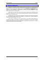
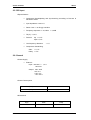
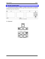
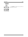
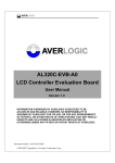
LCD-TFT MONITOR KIT
LM6005
USER MANUAL
LM6005D11
Edition 01
Jan 2005
KROMA
TELECOM
Pol. Ind. Alcobendas - C/ La Granja, 80
28108 Madrid - ESPAÑA
Tel. (34-91) 661 45 14
Fax. (34-91) 661 58 75
e-mail: [email protected]
Web: http://www.kromatelecom.com
KROMA TELECOM
LM6005
1. General Description...................................................................................... 3
2. Technical Specifications ............................................................................... 4
2.1. System ................................................................................................... 4
2.2. Picture Presentation ............................................................................... 4
2.3. TFT Screen ............................................................................................ 4
2.4. PAL/NTSC Decoder ............................................................................... 4
2.5. SDI Input ................................................................................................ 5
2.6. General................................................................................................... 5
3. Use and Operativeness ................................................................................ 7
3.1. Keyboard ................................................................................................ 7
3.1.1. Screen Selection .............................................................................. 8
3.1.2. Input Selection.................................................................................. 8
3.1.3. Picture adjustments .......................................................................... 9
3.1.4. Access to menu .............................................................................. 10
3.2. Menu .................................................................................................... 11
3.2.1. Status Menu ................................................................................... 11
3.2.2. Memory Recall Menu...................................................................... 11
3.2.3. Memory Store Menu ....................................................................... 11
3.2.4. Setup Menu .................................................................................... 12
3.2.4.1. Calibration Values Menu .......................................................... 12
3.2.4.2. Cal With Active Data................................................................. 13
3.2.5. Password Menu.............................................................................. 13
3.2.6. Program Function Menu ................................................................. 13
3.2.7. Remote Menu ................................................................................. 14
3.2.8. Configuration Values Menu ............................................................ 14
4. Installation .................................................................................................. 15
4.1. Mechanics ............................................................................................ 15
4.2. Power supply........................................................................................ 15
4.3. CCVS Video Inputs .............................................................................. 16
4.4. SDI Video Inputs .................................................................................. 16
4.5. TALLY .................................................................................................. 16
4.6. Comunications...................................................................................... 17
Edition 01
2
Jan 2005
KROMA TELECOM
LM6005
1. General Description
LM6005 is a monitoring kit that consists of three TFT screens of 5” provided each of
them with 2xPAL video inputs according to ITU-R-BT.470 (LM6005A11 and LM6005A12) and
2xSDI at 10 bits according to ITU-R BT.601, SMPTE 270 Mbit/s (LM6005A11). This
equipment is rack-mountable into standard 19 inches. Its brackets are provided with a tilting
feature that improves the viewing angle.
Above each TFT screen user will find a Tally led with double colour (red/yellow) that is
activated by contact closure; its reduced size and lightness make it ideal for live broadcasting,
CCU monitoring, OB vehicles, etc.
Operativeness is easy due to its front keyboard. Parameters are checked and adjusted
thru its On-Screen Display (OSD) and controlled by microprocessor. This also allows the
continuous software upgrade of the monitor.
This version of LM6005 has been improved with a new feature (Sleep Mode) that
prolonges the timelife of the screen. It switches off automatically in case of lack of signal
during a certain period of time (user-programmable). A keystroke or the connection of a signal
would get the monitor back to its active status.
Edition 01
3
Jan 2005
KROMA TELECOM
LM6005
2. Technical Specifications
2.1. System
• System:
625/50/2:1
525/60/2:1
• Horizontal frequency:
CCVS PAL
CCVS NTSC
15.625Hz (625/50)
15.734Hz (525/60)
2.2. Picture Presentation
• Aspect Ratio:
4:3
• Resolution:
> 280 líneas
• Colour Temperature:
6500º K ±200º
2.3. TFT Screen
• Size:
5” (diagonal)
• Resolution: 960x234 dots
• Active area: 102.72(H) x 74.53(V) mm
• Dot pitch:
0.107(H) x 0.319(V) mm
• Pixel Configuration: stripe
• Dimensions:
• Weight:
127.4(W) x 92.8(H) x 12.9(D) (typ.) mm
164±10 g
2.4. PAL/NTSC Decoder
• CCVS inputs
9 Level: 1 Vpp +3/-6 dB
9 Impedance: 75Ω ±1%
• Return Loss:
> 35 dB @ 5 MHz
• Crosstalk: > 60 dB @ 10 MHz.
Edition 01
4
Jan 2005
KROMA TELECOM
LM6005
2.5. SDI Input
• Especifications
9 Component Demultiplexing and Synchronizing according to Rec.601 &
Rec.656 of CCIR.
9 Input Impedance: 75Ω ±1%
9 Return Loss: > 15 dB @ 270 MHz
9 Frequency response: 0 – 5,5 Mhz. < 0,5 dB
9 Tilt (V): < 0,5 %
9 Factor K:
Kp < 0,3 %
Kpb < 0,2 %
9 Low frequency distorsion:
<1%
9 Component mismatching:
Gain: < 0,1 %
Delay: < 3 ns
2.6. General
• Power Supply
9 External.Input: 100-240 V ~ 1,3 A
50-60 Hz
Output: máx. 45W
+5V / 5 A
+12V / 3 A
-12V / 0.5 A
• Power Consumpsion
LM6005A12 (PAL):
21 W
LM6005A11 (DIG):
37 W
• Dimensions
Edition 01
High
Wide
Deep
118 mm
440 mm
60 mm
5
Jan 2005
KROMA TELECOM
LM6005
• Weight
Edition 01
LM6005-A12 (PAL):
2,5 Kg
LM6005-A11 (DIG):
2,65 Kg
6
Jan 2005
KROMA TELECOM
LM6005
3. Use and Operativeness
See below the fron panel of LM6005. It consists of three screen for monitoring
purposes, each of them with the tally led. On the right side user will find the function keys and
the ON/OFF switch with its power led.
Picture 3.1 Front panel
3.1. Keyboard
Picture 3.2 Keyboard
Edition 01
7
Jan 2005
KROMA TELECOM
LM6005
3.1.1. Screen Selection
User can adjust the parameters of one screen or the three of them at the same time1.
Note that screen are numbered from 1 to 3 from left to right.
Use ‘TFT SEL’ for selecting the desired screen. First keystroke will show the active
screen. The following ones will vary the selected screen: first screen, second, third, all of
them.
A message will appear on the upper side of the screen:
Picture 3.3 Screen selection
If the three screens are selected, every parameter
adjustment will act on all of them.
After a few seconds (or by pressing ‘MENU/ESC’ key), the message will
disappear.
3.1.2. Input Selection
Input is selected thru ‘INPUT SEL’ key. It follows this order:
CCVS 1
CCVS 2
CDV 1
CDV 2
Picture 3.4 LM6005A11 Switching order
Picture 3.5 LM6005A12 Switching order2
First keystroke will show the active screen. The following ones will vary the video input
as shown on the above pictures.
The active screen will tell which video input can be seen at that moment.
Picture 3.6 Input selection messages
1
2
At switching on the equipment, all three screens are active/selected.
LM6005A12 is not provided with SDI inputs.
Edition 01
8
Jan 2005
KROMA TELECOM
LM6005
If we select an input with no signal, a message as follows will appear on the left upper
side of the screen:
Picture 3.7 No signal message
After a few seconds (or by pressing ‘MENU/ESC’ key), the message
will disappear.
3.1.3. Picture adjustments
System allows user to adjust the following parameters: black level, contrast,
saturation and hue. Just press ‘ADJ SEL’ key as many times as needed to reach the desired
parameter. See below the order:
Picture 3.8 Parameter adjustment switching order
Press tu to change the desired parameter.
On the left lower side of the screen of the active
screen a message will appear showing the parameter,
its value and if it matches to its calibrated values (CAL).
If not (UNCAL), the red led will be on. Press ‘CAL’ to go
back to the calibrated values of such parameter. 3
DIODO LED UNCAL
When all parameters have its values adjusted to
the calibrated ones, the led will be off.
After a few seconds (or by pressing ‘MENU/ESC’ key), the message will
disappear.
3
All the parameters are calibrated from factory.
Edition 01
9
Jan 2005
KROMA TELECOM
LM6005
3.1.4. Access to menu
Press ‘MENU/ESC’ to entre/exit the menu. See below for a
detailed description of every feature.
Edition 01
10
Jan 2005
KROMA TELECOM
LM6005
3.2. Menu
Use tu to browse thru the menu. Press ‘CAL’ to validate and ‘MENU/ESC’ to exit. A
flickering will indicate the active option.
Use tu for entering numeric codes such as passwords and net IDs. Again, use ‘CAL’
to validate the desired digit.
Picture 3.9 How to browse the menu thru the keyboard
3.2.1. Status Menu
Press shortly ‘MENU/ESC’ to enter the main menu.
3.2.2. Memory Recall Menu
MEMORY RECALL menu allows the user to call the system
values stored either by an user or by technical staff (user 1 – user 4
and technical).
Use tu to place on the desired
memory and press ‘CAL’ to load these
values. A message on the process will
appear, indicating also the outcome
(DONE /ERROR).
3.2.3. Memory Store Menu
MEMORY STORE menu allows the user to store the current
values into the different available memories (user 1 – user 4,
technical and all). Such values would be loaded thru MEMORY
RECALL menu if necessary.
Use tu to place on the desired memory and press ‘CAL’ to
store.
Edition 01
11
Jan 2005
KROMA TELECOM
LM6005
Non-authorized users can be banned from modifying system values via password. If
user enters the wrong password, she will be taken right back to MEMORY STORE menu. A
message on the process will appear, indicating also the outcome (DONE /ERROR).
NB: Technical memory cannot be modified. That way factory values will be always
available. ALL MEM. can be used only by technical staff.
3.2.4. Setup Menu
SETUP menu allows the user to change system
values such as:
Calibration values (CALIBRATION VALUES).
To calibrate with current values (CAL WITH ACTIVE DATA).
This menu is password-protected to prevent unauthorized users from accessing this
critical menu.
3.2.4.1. Calibration Values Menu
CALIBRATION VALUES menu allows variation of black
level, contrast, saturation and hue.
Use tu keys to select the parameter to modify and
then press ‘CAL’. Use again tu keys to change the its values
and press ‘CAL’ to validate or ‘MENU/ESC’ key to exit (which
keeps the value unchanged).
Edition 01
12
Jan 2005
KROMA TELECOM
LM6005
3.2.4.2. Cal With Active Data
This option allows the user to calibrate the equipment with the current values. Just
press ‘CAL’. A message on the process will appear, indicating also the outcome (DONE
/ERROR).
3.2.5. Password Menu
This menu is aimed at changing user and system passwords.
Use tu keys to select the new numeric password and then
press ‘CAL’ to validate.
Old password will always be requested: If right, user might enter
the new one, which must be entered again. If not, she will be taken right back to the menu
(which keeps the old password unchanged).
3.2.6. Program Function Menu
PROGRAM FUNCTION menu allows to programme the
following features:
SDI FORMAT: for switching between SDI signals (625/50 or 525/60). Just press ‘CAL’.
SLEEP MODE: for automatically switching off the screen when no activity detected.
This improves the lifetime of the screen. If no signal is detected or key pressed, a 3-minute
timer will switch off the screen. Just press ‘CAL’ to activate/deactivate.
If on, a message on the remaining time will appear.
Edition 01
13
Jan 2005
KROMA TELECOM
LM6005
3.2.7. Remote Menu
REMOTE menu will help us identify each screen in order to
remotely control each parameter of it (thru RK50004). Otherwise user
might prefer to assign one ID to the three screens5. The range for the
IDs is from 0 to 254, so up to 255 screens can be controlled from this
remote equipment.
Press ‘CAL’ to modify the ID. Use tu keys to select the numeric code and then press
‘CAL’ to validate.
3.2.8. Configuration Values Menu
CONFIGURATION VALUES menu can be
entered by a long keystroke to ‘MENU/ESC’ key. This
can be done anytime and at any status. It will show the
current configuration of the equipment. See below the
different parameters displayed:
OPTIONS: It shows the activated options:
CCVS: Two composite video inputs (CCVS A and B).
SDI: Two SDI video inputs (S1 and S2).
SW VERSION: installed software version. Note that they are upgradable6.
PARAMETERS: With its current and calibration values.
4
For more info on RK5000, read its user manual.
Note that 000, 001 and 002 are screens´ IDs from factory.
6
Ask your supplier.
5
Edition 01
14
Jan 2005
KROMA TELECOM
LM6005
4. Installation
4.1. Mechanics
LM6005 fits a standard 19-inch rack. It is 118mm high, slightly less than 3RU so that it
can tilt for increasing the viewing angle. Its brackets turn on themselves in several steps up to
±25º.
On its rear panel it can be found: BNC connectors for the video inputs, plug for external
power supply, two RJ45 connectors for the remote feature explined above and the SubD for
the tally leds.
Picture 4.1 Rear panel
4.2. Power supply
Each LM6005 is provided with an external power supply that delivers three voltages:
Input:
110-240 Vac ~ 1.3A Max, 50-60 Hz
Output: +5 Vdc/5.0A
-12 Vdc/0.5A
+12 Vdc/3.0A
Power supply cable is 1,5m long, provided with a 4-pin XLR connector with locks to
avoid accidental disconnections. See below the pinout of the rear connector:
Pin 1: GND
Pin 2: -12Vdc/0.5A
Pin 3: +5Vdc/5.0A
Pin 4: +12Vdc/3.0A
Edition 01
15
Jan 2005
KROMA TELECOM
LM6005
4.3. CCVS Video Inputs
For each monitor screen, there
are associate two BNC connectors for
composite video inputs. A switch for
75 Ohm termination or loop-through
purpose is provided.
4.4. SDI Video Inputs
Also two BNC connectors
intended for SDI video inputs are
terminated with 75 Ohm load in order
to get the return loss proper to this
type of interface.
4.5. TALLY
Each screen is provided with a double-colour tally led (red/yellow), which is activated
by contact closure to ground. See below the pinout of the SUB-D connector:
PIN 1:
PIN 2:
PIN 3:
PIN 4:
PIN 5:
PIN 6:
PIN 7:
PIN 8:
PIN 9:
Edition 01
16
Red (Screen 1)
GND
Red (Screen 2)
Red (Screen 3)
No Connection
Yellow (Screen 1)
No Connection
Yellow (Screen 2)
Yellow (Screen 3)
Jan 2005
KROMA TELECOM
LM6005
4.6. Comunications
LM6005 is provided with two RJ45 connectors (8 pins) for managing the equipment
remotely thru KROMA RK5000. This device can remotely control all the parameters of a
monitoring panel of KROMA TFT monitors.
They are two connectors for looping
purposes. Pinout must be 1:1. Interface is of
RS485 type.
Edition 01
17
Jan 2005