1
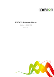
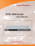
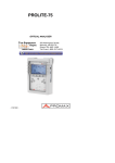
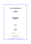
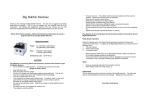
EN-264
DVB MPEG-4 HDTV ENCODER
& TRANSCODER
- 0 MI1720 -
SAFETY NOTES
Read the user’s manual before using the equipment, mainly " SAFETY RULES "
paragraph.
The symbol
on the equipment means "SEE INSTRUCTION MANUAL". In this
manual may also appear as a Caution or Warning symbol.
Boxes of WARNING AND CAUTION may appear in this manual to avoid hazard or
damage to people, to this product or other properties.
USER’S MANUAL. EN-264.
T A B L E OF C O N T E N T
1
2
3
4
5
GENERAL.................................................................................................................. 1
1.1 Description .......................................................................................................... 1
1.2 Features .............................................................................................................. 2
1.3 Especifications .................................................................................................... 2
SAFETY RULES........................................................................................................ 5
2.1 General safety rules ............................................................................................ 5
2.2 Descriptive Examples of Over-Voltage Categories ............................................. 6
INSTALLATION ......................................................................................................... 7
3.1 Front panel and rear panel instructions............................................................... 7
MENU STRUCTURE AND OPERATION INSTRUCTIONS. ..................................... 9
4.1 Menu operating instructions .............................................................................. 11
4.1.1 Status menu................................................................................................ 11
4.1.2 Encoder Setup menu .................................................................................. 12
4.1.3 Transcoder Setup Menu ............................................................................. 16
4.1.4 IP Board Setup Menu.................................................................................. 20
4.1.5 IP Board Setup Menu.................................................................................. 22
4.1.6 PID Processing Menu ................................................................................. 23
4.1.7 Output Setup Menu..................................................................................... 24
4.1.8 System Menu .............................................................................................. 24
4.2 Installation ......................................................................................................... 25
MAINTENANCE....................................................................................................... 27
5.1 Replacing the fuse............................................................................................. 27
5.2 Cleaning Recommendations ............................................................................. 27
USER’S MANUAL. EN-264.
USER’S MANUAL. EN-264.
DVB MPEG-4 HDTV ENCODER &
TRANSCODER
EN-264
1
1
GENERAL
1.1
Description
EN-264 is a HD Encoder & Transcoder which fully complies with H.264 standard.
Integrated with the TSoIP board, the accepts TS over IP or ASI input for transcoding, or
alternatively accepts HD-SDI, HDMI or YPbPr input for encoding, the final output is
available in IP or ASI format. With extraordinary picture quality and significant
bandwidth liberation, EN-264 is the best choice for higher performance encoding and
migration from MPEG-2 to H.264.
Functions
HD SDI Input
HDMI Input
Y/Pb/Pr Input
CVBS Input
Audio 1 Input
Audio 2 Input
ASI Input
ASI Output (x2)
10/100M TS Over IP
(6 Multicasts)
Remote Control
RS-232
1
05/2013
EN-264
√
√
√
√
√
√
√
√
√
√
√
Trademark of the DVB - Digital Video Broadcasting Project.
Page 1
USER’S MANUAL. EN-264.
1.2
Features
•
•
•
•
•
•
•
•
•
1.3
Conforms to H.264 High Profile 4.0 and Main Profile 4.0.
TS to TS Transcoding MPEG-2 HD to H.264 HD/SD, or MPEG-2 SD to H.264
SD.
Supports TS multiplexing, which can re-multiplex encoded programs and ASI
input programs into one TS stream.
Supports full full HD 1080i.
Multiple inputs HDMI, HD-SDI, YPbPr and CVBS for encoding.
Support VBR and CBR encoding mode.
Support Remux, can edit PSI/SI table information.
10M/100M Base-T TS over IP output.
Auto-save when power off.
Especifications
Video input and compression
Input interface
Compression format
Compression bit rate
Audio input and compression
Compression format
Signal sampling rate
Compression rate
Input type
HD/SD-SDI/HDMI/YpbPr,
interface.
AVC (H.264) encoding.
2~20 Mbps.
video
MPEG1 Layer2.
48 KHz.
32~256 Kbps, 64~448 Kbps/AC3.
Analog balance or unbalance audio interface
digital audio HD/SD-SDI HDMI.
DVB-ASI serial data input
Interface type
Data mode
Packet length
Signal level
75 Ω, BNC interface.
Byte mode
188/204 Bytes
800±80 mV.
DVB-ASI serial data output
Interface type
Data mode
Packet length
Signal level
Bit rate
75Ω, BNC interface.
Byte mode.
188 Bytes.
800±80 mV.
1.5~67 Mbps(adjustable).
Page 2
CVBS
05/2013
USER’S MANUAL. EN-264.
TS over IP output
100Base-T
Maximum output bit rate
Transport protocols
Multicast control protocol
RJ-45.
70 Mbits/s.
UDP/RTP, Multicast or Unicast.
IGMPV2.
ALIMENTATION
Power supply
Consumption
90~250V-50/60Hz.
19 W.
OPERATING ENVIRONMENTAL CONDITIONS
Altitude
Up to 2000 m.
Temperature range
From 0 to 45 °C.
Max. relative humidity
80 % (up to 31°C),
decreasing lineally up to 50% at 40 °C.
MECHANICAL FEATURES
Weight
Dimensions
3 Kg.
44 mm (W)× 240 mm (H)× 430 mm.
INCLUDED ACCESSORIES
1 x Coaxial cable.
1 x Power cable CA-05.
4 x RCA-BNC adapters.
2 x RCA-Audio adapters.
1 x DB9-Audio adapters (Left and right).
2 x Rack Handles.
1 x Certificate of Guarantee.
RECOMMENDATIONS ABOUT THE PACKING
It is recommended to keep all the packing material in order to return the
equipment, if necessary, to the Technical Service.
05/2013
Page 3
USER’S MANUAL. EN-264.
Page 4
05/2013
USER’S MANUAL. EN-264.
2
SAFETY RULES
2.1
General safety rules
∗
The safety could not be assured if the instructions for use are not closely
followed.
∗
Use this equipment connected only to systems with their negative of
measurement connected to ground potential.
∗
The equipment is a Class I equipment, for safety reasons plug it to a supply line
with the corresponding ground terminal.
∗
This equipment can be used in installations with Overvoltage Category I and
environments Pollution Degree 2.
∗
When using some of the following accessories use only the specified ones to
ensure safety:
Power cord.
∗
Observe all specified ratings both of supply and measurement.
∗
Remember that voltages higher than 70 V DC or 33 V AC rms are dangerous.
∗
Use this instrument under the specified environmental conditions.
∗
The user is only allowed to:
-
Change fuses. They must be of the type and value specified.
-
At the maintenance paragraph, specific instructions are provided for these
interventions.
-
Any other change in the equipment must be exclusively carried out by
specialized technician staff.
∗
Negative of the signal is at ground potential.
∗
Do not obstruct the ventilation system of the equipment.
∗
Use for the signal inputs/outputs, specially when working with high levels,
appropriate low radiation cables.
∗
Follow the cleaning instructions described in the Maintenance paragraph.
05/2013
Page 5
USER’S MANUAL. EN-264.
∗
Symbols related with safety:
2.2
Descriptive Examples of Over-Voltage Categories
Cat I
Low voltage installations isolated from the mains.
Cat II
Portable domestic installations.
Cat III
Fixed domestic installations.
Cat IV
Industrial installations.
Page 6
05/2013
USER’S MANUAL. EN-264.
3
INSTALLATION
3.1
Front panel and rear panel instructions
Front panel
Figure 1.-
A1
POWER
Power indicator, green light means power supply is
good.
A2
ASI IN
ASI input signal indicator, green light means ASI
signal input is good, when the light is off means
there is no ASI signal input.
Note: When IP is set to IP IN mode, this light
displays IP IN status.
A3
ENCODER
Encoding signal indicator, green light means
encoding is good, when the light is off means there
is no encoding going on.
A4
LCD
2 x 20 LCD display.
A5 - A10 BUTTONS
05/2013
,
Used to navigate within a single menu
level, select functions, and change
values.
,
Used to move the cursor.
ENTER
Used to enter lower menu or to
confirm the choices.
EXIT
Used to pass to an upper menu level
or to cancel the choices.
Page 7
USER’S MANUAL. EN-264.
Rear panel
Figure 2.-
Page 8
B1
TS/IP
TS over IP output.
B2
ASI IN
ASI input interface.
B3-B4
ASI OUT
ASI output interface B3 and B4 have same
contents.
HDMI input interface.
B5
HDMI
B6
HD/SD SDI IN HD/SD SDI input interface.
B7
CVBS
Composite video input interface.
B8,B9,B10 Y,Pb,Pr
Analog component input interface.
B11
AUDIO2 IN
Audio input interface AUDIO2.
B12
AUDIO1 IN
Audio input interface AUDIO1.
B13
Control
Network management interface, for remote control.
B14
RS-232
Serial printer.
B15
GND
Grounding.
B16
Fusible
Fuse power supply.
B17
Alimentation
AC 90~250V input.
B18
I/O
On / Off switch.
05/2013
USER’S MANUAL. EN-264.
4
MENU STRUCTURE AND OPERATION
INSTRUCTIONS.
05/2013
Page 9
USER’S MANUAL. EN-264.
Figure 3.-
Page 10
05/2013
USER’S MANUAL. EN-264.
4.1
Menu operating instructions
2 row x 20 symbol LCD displays below information after being turned on.
First row displays the name of the product; second row displays local IP address.
Press ENTER to get in the main menu:
Figure 4.-
4.1.1 Status menu
Includes three options, displays input interface parameters. Menu format as
shown below:
Figure 5.-
ASI Input Bit Rate
menu
Displays the TS total bit rate and effective bit rate of the ASI
input.
Note: When IP is set to input mode, here displays TS total
bit rate and effective bit rate of the IP input.
Encoder Bit Rate
menu
Video Input Format
Menu
05/2013
Displays the TS total bit rate and effective bit rate encoder
output.
Displays the input video format (but can not confirm all
video format).
Page 11
USER’S MANUAL. EN-264.
4.1.2 Encoder Setup menu
It includes 6 options which configure the encoder parameters. Menu format is
shown as below:
Figure 6.-
Work Mode Menu
It includes encode and transcode mode options.
If you want to encode programs, please set it as
Encode mode.
If want to transcode programs, set it as Transcode
mode. The menu will be changed basing on different
modes.
Encoder Start Menu
Encode Start: press the button ENTER to enter, press
ENTER to apply parameters for encoding, press EXIT
to continue modify the encoding parameters.
Note: After setting all parameters please press ENTER
to save all parameters and start work.
Video Setup Menu
It includes Video Rate Ctl, Format, Video Bit Rate,
Aspect Ratio and Video Input Source.
Video Rate Ctl:
Enter the menu to select CBR or VBR, press ENTER
to confirm the setting.
Format:
Enter the menu to select the input video format, here
are the options:
1920x1080i 29.97, 1920x1080i 25,
1440x1080i 29.97, 1440x1080i 25,
1280x720p 59.94, 1280x720p 50,
720x480i 29.97, 720x576i 25
Then press ENTER to confirm the setting.
Note: Please make sure the video source resolution
you select is the same as the actual imported video
source resolution.
Page 12
05/2013
USER’S MANUAL. EN-264.
Video Bit Rate:
Enter the menu to set the bitrate of the encoded video,
then press ENTER to confirm the setting.
Aspect Ratio:
Enter the menu to set the video proportion 4:3 or 16:9.
Press ENTER to confirm the setting.
Video Input Source:
Enter the menu to select the source of video input, you
can select the video from:
SDI Video; HDMI Video; Composite Video (only
support Standard Definition); YPbPr Video (only
support High Definition).
Press ENTER to confirm the setting.
Audio Setup Menu
Audio1 Format:
It includes Audio1 Format, Audio1 Bit Rate,
Channel, Audio1 Level, Audio1 Input Source,
SDI EMB, Audio2 Format, Audio2 Bit Rate,
Channel, Audio2 Level, Audio2 Input Source,
SDI EMB.
Audio1
Audio1
Audio2
Audio2
Enter the menu to select the audio format:
MPEG1 Layer2.
Press ENTER to confirm the setting.
Audio1 Bit Rate:
Enter the menu to set the audio bitrate, you can select
from the following options:
32kbps; 48kbps; 56kbps; 64kbps; 80kbps; 96kbps;
112kbps; 128kbps; 160kbps; 192kbps; 224kbps;
256kbps; 320kbps; 384kbps.
Press ENTER to confirm the setting.
Audio1 Channel:
Enter the menu to set the audio channel, you can
select Stereo / Mono.
Press ENTER to confirm the setting.
Audio1 Level:
Enter the menu to set the volume of output voice.
Press ENTER to confirm the setting.
Regulating range of volume: +6 dB ∼ -17 dB.
Audio1 Input Source: Enter the menu to select the source of audio, you can
select from the following options:
SDI; HDMI; Composite2; Composite1.
Press ENTER to confirm the setting.
05/2013
Page 13
USER’S MANUAL. EN-264.
Audio1 SDI EMS:
Enter the menu to select:
EMS1; EMS2; EMS3; EMS4.
Press ENTER to confirm the setting.
Note: this option is active only the audio1 Input Source
is SDI audio.
Audio2 Format:
Enter the menu to select the audio format:
MPEG1 Layer2.
Press ENTER to confirm the setting.
Audio2 Bit Rate:
Enter the menu to set the audio bitrate, you can select
from the following options:
32kbps; 48kbps; 56kbps; 64kbps; 80kbps; 96kbps;
112kbps; 128kbps; 160kbps; 192kbps; 224kbps;
256kbps; 320kbps; 384kbps.
Press ENTER to confirm the setting.
Audio2 Channel:
Enter the menu to set the audio channel, you can
select Stereo / Mono.
Press ENTER to confirm the setting.
Audio2 Level:
Enter the menu to set the volume of output voice.
Press ENTER to confirm the setting.
Regulating range of volume: +6 dB ∼ -17 dB.
Audio2 Input Source: Enter the menu to select the source of audio, you can
select from the following options:
SDI; HDMI; Composite2; Composite1.
Press ENTER to confirm the setting.
Audio2 SDI EMS:
Enter the menu to select:
EMS1; EMS2; EMS3; EMS4.
Press ENTER to confirm the setting.
Note: this option is active only the audio2 Input Source
is SDI audio.
Page 14
05/2013
USER’S MANUAL. EN-264.
Encoder Bit Rate Menu
TS Bit Rate:
Enter the menu to set the TS Bit Rate.
Press ENTER to confirm the setting.
Please be noted that the value of the TS Bit Rate
should be larger than the sum of video bitrate and audio
bitrate.
Advanced Setup Menu
Output PMT PID:
Includes Output PMT PID, Output Video PID, Output
Audio1 PID, Output Program Num, Output PCR PID,
Output Service Name, Output Audio2 PID and PTS
Time Set.
Enter the menu to set the output PMT PID.
Press ENTER to confirm the setting.
Note: PID must be less than 8191 more than 31 and
each PID are difference.
Output Video PID:
Enter the menu to set the output Video PID.
Press ENTER to confirm the setting.
Note: PID must be less than 8191 more than 31 and
each PID are difference.
Output Audio1 PID:
Enter the menu to set the output Audio1 PID.
Press ENTER to confirm the setting.
Note: PID must be less than 8191 more than 31 and
each PID are difference.
Output Program Num: Enter the menu to set the output Program Num.
Press ENTER to confirm the setting.
Output PCR PID:
Enter the menu to set the output PCR PID.
Press ENTER to confirm the setting.
Note: PID must be less than 8191 more than 31 and
each PID are difference.
Output Service Name: Enter the menu to set the output Service Name.
Press ENTER to confirm the setting.
05/2013
Page 15
USER’S MANUAL. EN-264.
Output Audio2 PID:
Enter the menu to set the output Audio2 PID.
Press ENTER to confirm the setting.
The default is 8191, when set Audio2, please change
the PID as required.
Note: PID must be less than 8191 more than 31 and
each PID are difference.
PTS Time Set:
Enter the menu
synchronization.
to
set
the
audio
and
video
Press ENTER to confirm the setting.
4.1.3 Transcoder Setup Menu
It includes 10 options which configure the encoder parameters. Menu format is
shown as below:
Figure 7.-
Work Mode Menu
It includes encode and transcode mode options.
If you want to encode programs, please set it as
Encode mode.
If want to transcode programs, set it as Transcode
mode.
The menu will be changed basing on different modes.
Transcoder Start Menu
Transcoder Start:
Enter the menu to apply the parameters.
Press EXIT to continue modify the parameters.
Note: Please save all setting
transcoding, press ENTER to work.
Page 16
parameters
for
05/2013
USER’S MANUAL. EN-264.
Video Setup Menu
Video Rate Ctl:
It includes: Video Rate Ctl, Format, Video Bit Rate,
Aspect Ratio you can control Video bitrate, mode
selection and Video bitrate setting.
Enter the menu to select CBR or VBR.
Press ENTER to confirm the setting.
Format:
Enter the menu to select the input video format, here
are the options:
1920x1080i 29.97; 1920x1080i_25; 1440x1080i_29.97;
1440x1080i 25; 1280x720p 59.94, 1280x720p 50;
720x480i 29.97; 720x576i 25; 704x480i 29.97;
704x576i 25.
Then press ENTER to confirm the setting.
Video Bit Rate:
Enter the menu to set the bitrate of the output video.
Then press ENTER to confirm the setting.
Aspect Ratio:
Enter the menu to set the video proportion: 4:3 or 16:9.
Then press ENTER to confirm the setting.
Audio Setup Menu
Audio1 Format:
It includes Audio1 Format, Audio2 Format, Encode
Audio2 BitRate, Encode Audio2 channel, Encode
Audio2 Level, Encode Audio2 Source, Encode SDI
Audio2.
Enter the menu to select the audio format:
MPEG1 Layer2, AC3, MPEG2 AAC.
Press ENTER to confirm the setting.
Audio2 Format:
Enter the menu to select the audio format:
MPEG1 Layer2, AC3, MPEG2 AAC.
Press ENTER to confirm the setting.
Encode Audio2
BitRate:
Enter the menu to select audio bitrate 32k, 64k, 128k,
192k, 256k, 384k.
Press ENTER to confirm the setting.
Encode Audio2
Channel:
Enter the menu to select Stereo/Mono.
Press ENTER to confirm the setting.
05/2013
Page 17
USER’S MANUAL. EN-264.
Encode Audio2 Level: Enter the menu to set the volume of audio.
Press ENTER to confirm the setting.
Regulating range of volume: +6 dB ∼ -17 dB or mute.
Encode Audio2
Source:
Enter the menu to set the audio source , you can
select SDI, HDMI, Composite2, Composite1.
Press ENTER to confirm the setting.
Encode SDI Audio2:
Enter the menu to select EMS1, EMS2, EMS3, EMS4.
Press ENTER to confirm the setting.
Note: This option is active only the audio2 Input
Source is SDI audio.
Transcode Bit Rate Menu:
Enter the menu to set the TS Bit Rate.
Press ENTER to confirm the setting.
Please be noted that the value of the TS Bit Rate
should be larger than the sum of video bitrate and
audio bitrate.
Advanced Setup Menu
Output PMT PID:
Enter the menu to set the output PMT PID.
Press ENTER to confirm the setting.
Note: PID must be less than 8191 more than 31 and
each PID are different.
Output Video PID:
Enter the menu to set the output Video PID.
Press ENTER to confirm the setting.
Note: PID must be less than 8191 more than 31 and
each PID are different.
Output Audio1 PID:
Enter the menu to set the output Audio1 PID.
Press ENTER to confirm the setting.
Note: PID must be less than 8191 more than 31 and
each PID are different.
Output Program Num: Enter the menu to set the Program Number.
Press ENTER to confirm the setting.
Page 18
05/2013
USER’S MANUAL. EN-264.
Output PCR PID:
Enter the menu to set the output PCR PID.
Press ENTER to confirm the setting.
Note: PID must be less than 8191 more than 31 and
each PID are different.
Output Service
Name:
Enter the menu to set the output Service Name.
Press ENTER to confirm the setting.
Output Audio2 PID:
Enter the menu to set the output Audio2 PID.
Press ENTER to confirm the setting.
Note: PID must be less than 8191 more than 31 and
each PID are different.
Output Audio3 PID:
Enter the menu to set the output Audio3 PID.
Press ENTER to confirm the setting.
Note: PID must be less than 8191 more than 31 and
each PID are different.
PTS Time Set:
Enter the menu
synchronization.
to
set
the
audio
and
video
Press ENTER to confirm the setting.
Note: range from 0 ∼ 800.
Input Video Format Menu
Enter the menu to select the input video format, here
are the options:
1920x1080i 29.97; 1920x1080i_25; 1440x1080i_29.97;
1440x1080i 25; 1280x720p 59.94, 1280x720p 50;
720x480i 29.97; 720x576i 25; 704x480i 29.97.
Press ENTER to confirm the setting.
Input Program List Menu
Enter the Input ASI menu to look up the input program
need to be transcoded, the chosen program will shown
with a “ ”, press EXIT to quit.
Note: When IP board is set to IP IN mode, here shows
the program list of IP input.
05/2013
Page 19
USER’S MANUAL. EN-264.
Transcoder Audio
PID1 Menu
Enter the menu to set the transcoding Audio1 PID.
Press ENTER to confirm the setting.
Note: PID must be less than 8191 more than 31 and
each PID are different.
Note: When choosing program to be transcoded in the
Input Program List, here shows the corresponding
Audio PID. When the program to be transcoded has
several Audio PID, you can set Audio PID you want in
this menu.
Transcoder Audio
PID2 menu
Enter the menu to set the transcoding Audio2 PID.
Press ENTER to confirm the setting.
4.1.4 IP Board Setup Menu
It includes 15 options which configure the encoder parameters. Menu format is
shown as below:
Figure 8.-
IP Board IP Address Menu TS/IP output interface IP Address. Enter the menu to
set the IP Address.
Press ENTER to confirm the setting.
IP Board Net Mask Menu
TS/IP output interface Net Mask. Enter the menu to set
the Net Mask.
Press ENTER to confirm the setting.
IP Board Gateway Menu
TS/IP output interface Gateway. Enter the menu to set
the Gateway.
Press ENTER to confirm the setting.
Page 20
05/2013
USER’S MANUAL. EN-264.
IP Board MAC Address
Menu
Protocol Menu
Enter the menu to examine the IP Board MAC
Address.
Enter the menu to choose from UDP or RTP protocol.
Press ENTER to confirm the setting.
TS Pkts Per UDP Menu
Enter the menu to set the number of TS packets per
UDP, the number can be chosen from 1~7.
Press ENTER to confirm the setting.
Time To Live Menu
Enter the menu to set the Time To Live.
Press ENTER to confirm the setting.
Type Of Service Menu
Enter the menu to set the Type Of Service, here are
the options: Min Delay, Max Reliability, Max
Throughput, Min Monetary, Normal.
Press ENTER to confirm the setting.
Gate MAC Address Menu
Enter the menu to set the Gate MAC Address.
Press ENTER to confirm the setting.
Multicast1 Menu
It includes Multicast IP Address, Multicast UDP Port,
Target MAC Address, Mode and Program List options.
Multicast IP Address: Enter the menu to set the address range from
224.0.0.0 to 239.255.255.255.
Press ENTER to confirm the setting.
Multicast UDP Port:
Enter the menu to set the Multicast UDP Port.
Press ENTER to confirm the setting.
Target MAC Address: Enter the menu to set the Target MAC Address.
Press ENTER to confirm the setting.
Mode:
Enter the menu to set the mode, here are the options:
Filter; Off; All Pass.
Press ENTER to confirm the setting.
Program List:
Enter the Program List menu to look up the output
program, press ENTER to choose or cancel, the
chosen program will shown with a “ ”, press EXIT to
quit.
Note: This only works when Mode is set to Filter.
Multicast 2~6 menu is as same as Multicast1 menu.
05/2013
Page 21
USER’S MANUAL. EN-264.
4.1.5 IP Board Setup Menu
It includes 9 options which configure the encoder parameters. Menu format is
shown as below:
Figure 9.-
IP Board IP
Address Menu
Enter the menu to set the TS/IP interface IP Address.
Press ENTER to confirm the setting.
IP Board Net Mask Menu
Enter the menu to set the TS/IP interface Net Mask.
Press ENTER to confirm the setting.
IP Board Gateway Menu
Enter the menu to set the TS/IP interface Gateway.
Press ENTER to confirm the setting.
IP Board MAC Address
Menu
Enter the menu to examine the IP Board MAC
Address.
Multicast IP Address Menu Enter the menu to set the Multicast IP Address
ranging from 224.0.0.0 ~ 239.255.255.255.
Press ENTER to confirm the setting.
Multicast UDP Port Menu
Enter the menu to set the Multicast UDP Port.
Press ENTER to confirm the setting.
Protocol Menu
Enter the menu to choose from UDP or RTP protocol.
Press ENTER to confirm the setting.
Output Smoothing Menu
Enter the menu to choose from:
Auto; Fixed Rate; Disable.
Press ENTER to confirm the setting.
TS Bit Rate Menu
Enter the menu to set the TS Bit Rate.
Press ENTER to confirm the setting.
Page 22
05/2013
USER’S MANUAL. EN-264.
4.1.6 PID Processing Menu
It includes 4 options, menu format is shown as below:
Figure 10.-
Program List Menu
ASI Input:
It includes ASI Input and Encoder options.
Enter the ASI Input menu to look up the input program,
the chosen program will shown with a “ ”, press EXIT
to quit.
Note: When IP board is set to IP IN mode, it will show
the program list of IP input here.
Encoder:
Set Transport Stream ID
Menu
Encode program list, remux the encode programs and
ASI IN programs. Enter the menu to choose or cancel
the program using the ENTER button, the chosen
program will shown with a “ ”, press EXIT to quit.
Enter the menu to set the Transport Stream ID.
Press ENTER to confirm the setting.
MUX Bit Rate Menu
Enter the menu to set the total TS output bitrate after
multiplexing.
Press ENTER to confirm the setting.
MUX Menu
05/2013
Press ENTER to to confirm the MUX output, press
EXIT to quit the modification.
Page 23
USER’S MANUAL. EN-264.
4.1.7 Output Setup Menu
It includes 1 option, menu format is shown as below:
Figure 11.-
Out Source Menu
Enter the menu to choose output mode, you can select
Encode/Transcode, MUX, ASI/IP.
Press ENTER to confirm the setting.
4.1.8 System Menu
It includes 9 options which configure the encoder parameters. Menu format is
shown as below:
Figure 12.-
Local Setting Menu
IP Address:
It includes: IP Address, Net Mask, Gateway and MAC
Address.
Enter the menu to set IP Address.
Press ENTER to confirm the setting.
Net Mask:
Enter the menu to set Net Mask.
Press ENTER to confirm the setting.
Gateway:
Enter the menu to set Gateway.
Press ENTER to confirm the setting.
Page 24
05/2013
USER’S MANUAL. EN-264.
MAC Address:
Enter the menu to set MAC Address.
Press ENTER to confirm the setting.
Remote Setting Menu
Enter the menu to set the Trap IP Address.
Unit Name Menu
Enter the menu to set the Unit Name.
Press ENTER to confirm the setting.
Press ENTER to confirm the setting.
Software Version Menu
Enter the menu to examine the Software Version.
Press EXIT to quit the menu.
Extend Board Select Menu Enter the menu to set the IP board mode here are the
options: IP Out Board; IP IN Board; No Out Board.
Press ENTER to confirm the setting.
Factory Settings Menu
Show the Serial number.
Login ID Menu
User name of Web is root or you can modify as
required.
Login Password Menu
Password is 12345 or you can modify as required.
4.2
Installation
Fix the device in the standard 19” rack.
Connect the power cable. Turn on the device and wait for 8 to 10 seconds,
while the device will complete self inspection and configuration. The
POWER Indicator LED will always light on during working. If not use the
device, please pull out the AC plug. If you want to reboot device, please
leave it for at least 5 seconds after shutting it down.
05/2013
Page 25
USER’S MANUAL. EN-264.
Page 26
05/2013
USER’S MANUAL. EN-264.
5
MAINTENANCE
5.1
Replacing the fuse
The fuse holder is located on the rear panel of the equipment.
NOTE: Disconnect the power cord before replacing the fuse.
Remove the fuse using a screwdriver. Replace the damaged fuse with a proper
new one and put again the fuse holder in its place.
The fuse must be:
FAILURE TO
EQUIPMENT.
5.2
COMPLY
5 x 20 2A F 250V.
THESE
INSTRUCTIONS
COULD
DAMAGE
THE
Cleaning Recommendations
CAUTION
To clean the cover, take care the instrument is disconnected.
CAUTION
Do not use scented hydrocarbons or chlorized solvents. Such products may
attack the plastics used in the construction of the cover.
The cover should be cleaned by means of a light solution of detergent and water
applied with a soft cloth.
Dry thoroughly before using the system again.
CAUTION
Do not use for the cleaning of the front panel and particularly the viewfinders,
alcohol or its derivatives, these products can attack the mechanical properties of
the materials and diminish their useful time of life.
05/2013
Page 27