1
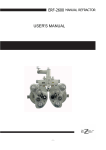
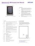
LCD-TFT Monitors LM5109 User Manual LM5109D11 Edition 01 January 2005 KROMA TELECOM Pol. Ind. Alcobendas - C/ La Granja, 80 28108 Madrid - ESPAÑA Tel. (34-91) 661 45 14 Fax. (34-91) 484 03 49 e-mail: [email protected] User Manual LM5109 INDEX 1. FRONT PANEL ..................................................................................................................................2 1.1. DESCRIPTION AND FUNCTIONS ...........................................................................................3 2. REAR PANEL .....................................................................................................................................4 2.1. DESCRIPTION AND FUNCTIONS OF EACH PART ..............................................................6 3. CONNECTIONS..................................................................................................................................8 3.1. EXTERNAL POWER SUPPLY ..................................................................................................8 3.2. EXTERNAL AUDIO INPUTS ....................................................................................................8 4. KEYBOARD........................................................................................................................................9 4.1. KEYBOARD – HOW IT WORKS ............................................................................................10 5. MENUS ..............................................................................................................................................11 5.1. STATUS MENU ........................................................................................................................11 5.2. MEMORY RECALL MENU.....................................................................................................13 5.3. SETUP MENU ...........................................................................................................................14 4.3.1. MANUAL SETUP MENU......................................................................................................15 4.3.1.1.CALIBRATION VALUES MENU....................................................................................15 4.3.1.3. COLOUR SETTING MENU ............................................................................................16 4.3.1.4. CAL WITH ACTIVE DATA ............................................................................................17 4.3.1.5. SYSTEM OPTIONS CONFIGURATIONS MENU .........................................................17 4.3.1.6. OSD LANGUAGE ............................................................................................................18 5.4. PASSWORD MENU..................................................................................................................19 4.4.1. EXPLANATORY NOTE ON PASSWORDS .........................................................................20 5.5. TECHNICAL MENU.................................................................................................................20 5.6. MEMORY STORE MENU ........................................................................................................21 5.7. 5.8. PROGRAM FUNCTION MENU ..............................................................................................22 EMBEDDED AUDIO MENU (SDI ONLY) .............................................................................24 -1- User Manual LM5109 1. FRONT PANEL E D A B C A) Switching on/off B) Calibration Led C) Optical Encoder D) Keyboard E) Screen Protective Film -2- User Manual LM5109 1.1. DESCRIPTION AND FUNCTIONS Switching on/off A lighted green led, located above the switcher, will indicate that equipment is operative. Calibration led The calibration led will be on when operative values of the equipment and its default ones mismatch. If they both are the same, it´ll be off. Depending on the input, parameters that are taken into account are: - Brightness, contrast and saturation for PAL/SECAM video inputs. - Brightness, contrast, saturation and hue for NTSC video inputs. - Brightness and contrast for SDI video inputs and PC input (RGB). Optical encoder Optical encoder is used for moving thru the menus and varying system values. When moved clockwise, values will be increased. Keyboard Keys allow user to directly operate the equipment with entering the menu. Screen Protective Film In order to avoid the screen being hit or damaged from external agressions, a resistant protective plastic film has been attached. It is anti-reflective as well. As it is adhered, it might be replaced for a new one if needed. Note that a transparent thin film covers the equipment when departs from Kroma. Kindly remove it to start working with the TFT Monitor. -3- User Manual LM5109 2. REAR PANEL J I D F C J E A G I H B -4- User Manual LM5109 A) Power Supply B) Serial Number. C) Audio Inputs. D) Software upgrade connector E) Composite video inputs (A, B) F) SDI video input (S1, optional) G) Protective gears for BNC connectors H) Battery support I) Power supply selection J) Termination for composite video inputs -5- User Manual LM5109 2.1. DESCRIPTION AND FUNCTIONS OF EACH PART Power supply This equipment can be powered from the mains thru external power supply. For this option, switch “I” to DC-IN mode. Serial number This label distinguished three parts: - Serial number of the equipment. - Options activated (CCVS and/or SDI modules). Audio inputs This equipment is provided with two analogue audio inputs. They can be output thru the built-in speaker at a side of the monitor. Composite video inputs This equipment is provided with two composite video inputs (CCVS A, CCVS B) for PAL, PAL-M, NTSC or SECAM signals. SDI inputs This equipment is provided with one SDI video input (S1) with passive loopthrough (75 Ω load). If loop remains unused, line must be terminated with a 75Ohm load. Protective gears for BNC connectors This equipment is provided with two security bows for protecting the BNC connectors from accidental bumps. Battery support This equipment can be powered with the following batteries: - Anton Bauer. Sony (type BP). For this option, switch “I” to BAT mode. -6- User Manual LM5109 Power supply selection This equipment can be powered either thru mains or batteries. User might select the type of power supply thru the switcher. Termination Each CCVS video input consists of two connectors for passive looping. If not used, switch the termination (“J”) from HI to 75 Ω. -7- User Manual LM5109 3. CONNECTIONS 3.1. EXTERNAL POWER SUPPLY This equipment can be powered from an external power supply. See below the pinout. Note that switcher (“I”) must be at DC IN mode. • • 3.2. Pins 1 and 2: +12 V DC. Pins 3 and 4: GND. EXTERNAL AUDIO INPUTS This equipment is provided with two connectors for external audio signal monitoring. Pinout is as follows: • • • Pin 1: Audio signal +. Pin 2: Audio signal -. Pin 3: GND. Audio inputs are designed to receive balanced signals. For a “single-ended” connection, use input + and connect input – to GND. -8- User Manual LM5109 4. KEYBOARD Keys allow user to directly operate the equipment without entering the menus. CCVS: Composite video input selection. First keystroke will indicate the chosen video input. Second and successive will change the video inputs. A message on screen will show the chosen input, its presence or not, and its format. After a while (or pressing ESC), this message will disappear. CDV: SDI video input selection. If SDI option is activated, a message will appear indicating this input and its presence or not. If the SDI option is not installed, a message indicating a non-activated option will appear. After a while (or pressing ESC), this message will disappear. CNT: Contrast control. A keystroke will show actual value and if matches calibrated values (CAL) or not (UNCAL). Vary this parameter with the optical encoder (“C” at the front panel). Press CAL to calibrate contrast. After a while (or pressing ESC), this message will disappear. BLK: Brightness control. A keystroke will show actual value and if matches calibrated values (CAL) or not (UNCAL). Vary this parameter with the optical encoder (“C” at the front panel). Press CAL to calibrate brightness. After a while (or pressing ESC), this message will disappear. SAT: Saturation Control. Used only with composite video signals. A keystroke will show actual value and if matches calibrated values (CAL) or not (UNCAL). Vary this parameter with the optical encoder (“C” at the front panel). Press CAL to calibrate saturation. After a while (or pressing ESC), this message will disappear. VOL: Volume Control. For varying volume level of the following two signals: - Speaker volume, at a side of the monitor. - Audio extracted from the signal is adapted towards the speaker. The volume of this signal can be changed as well. Sometimes it´s advisable to adjust both levels to get a perfect audio monitoring. This VOL key is configurable thru PROGRAM FUNCTION menu. AUD: Configurable thru PROGRAM FUNCTION menu. It might have the following uses: -9- User Manual LM5109 - Access to EMBEDDED AUDIO menu. A keystroke will make this menu appear without entering Status Menu. - Selection of De-embedded Audio Channel: For choosing the different channels (1, 2, 3, 4) that will be output out of the embedded audio. First keystroke will indicate the chosen audio channel. Second and successive will change the audio outputs. After a while (or pressing ESC), this message will disappear. - Selection of External Audio Signal: For choosing the different audio signals (embedded audio, external 1, external 2) that will be output thru the speaker. First keystroke will indicate the chosen output. Second and successive will change it. STS: Access to System menu ESC: Cancel or exit an operation. CAL: For returning to calibrated values or selecting a menu option. Nota that if pressed during 2+ seconds, calibration will affect all system parameters. 4.1. KEYBOARD – HOW IT WORKS ¾ Numbers above the keys are aimed at entering user passwords and numeric data (such as network “ID” of the monitor or module activation codes). ¾ There is no need to wait that a message disappear. If needed, press another key even if a message remains on screen. It´ll automatically operate according to the second key function. - 10 - User Manual LM5109 5. MENUS Menus allow the user to view, configure, store and call system values. Press STS key (Status) at the front panel as follows: Read below about the different menus that will be available. 5.1. STATUS MENU STATUS menu is the main menu as it allows access to all operations. To enter a menu, move the optical encoder (“C” at the fron panel) to the desired menu. Then press CAL. For example, if we want to enter SETUP menu, move the optical encoder clockwise to increase the selection window: Then press CAL to enter the desired menu. - 11 - User Manual LM5109 For escaping the menu, press ESC and it´ll disappear. When STS key is pressed twice, CONFIGURATION VALUES menu will appear. See below: This menu shows actual configuration of the equipment. It consists of: - * BOARDS: It shows the installed and activated options. AUD and CCVS will always be installed and activated while others will depend on the equipment characteristics. AUD: two analogue audio inputs (AUDIO CH1, CH2). CCVS: two analogue video inputs (CCVS A, B). CDV: one SDI video input (S1). - VERSION: It shows the softare version installed. Note that they might be upgraded*. - SYSTEM: It shows some hardware error. If none, an OK will appear. If yes, an error code will appear*. Check with your supplier - 12 - User Manual LM5109 - FPGA VERSION: It shows the FPGA configuration of the equipment. As it happens with the software version, it might be upgraded. - EQUIPMENT VALUES: Finally, different parameters of the equipment will appear (actual and calibration values). For exiting the menu, press STS or ESC. 5.2. MEMORY RECALL MENU Secuencia de acceso MEMORY RECALL menu allows the user to load the values previously stored at the four user memories (or the technical memory as well). Parameters recovered are: - Control values (brightness, contrast, saturation...) and calibration values. - Audio values (volume, group and audio output channel). - Values of PROGRAM FUNCTION menu. With the optical encoder, simply place the selection window at the desired memory to recall. Then press CAL. A message about recovery progress will appear and if it has been done correctly (DONE /ERROR). Steps to recall user memory 1 - 13 - User Manual LM5109 For exiting the menu, press ESC. Notes Have in mind that, unless changed by user, all memories are set with the technical values. 5.3. SETUP MENU Steps to access Setup menu SETUP menu allows the user to change the following parameters of the equipment: - Calibration Values (CALIBRATION VALUES MENU). Colorimetry Values (COLOUR SETTINGS). Calibration of the equipment with the actual values (CAL WITH ACTIVE DATA). Configuration of the installed options of the equipment (CONFIG. OPTIONS). Configuration of the OSD language (OSD LANGUAGE). For having access to these posibilities, a password needs to be entered. This way, no unauthorized user can modify the equipment values. Password requested is of the system. For entering it, use the numbers above the keys. - 14 - User Manual LM5109 If password is right, user will enter MANUAL SETUP menu. If wrong, she will return to STATUS menu. 4.3.1. MANUAL SETUP MENU From this menu, equipment values can be edited and/or modified. 4.3.1.1.CALIBRATION VALUES MENU Access sequence CALIBRATION VALUES menu allow the user to modify contrast, brightness, saturation (only analogue CCVS), hue (only NTSC) and dimmer. Every time real (A) and calibrated (C) values of the parameter where window is located will be shown. For modifyng a parameter, select it thru the optical encoder (C at the front panel). Then press CAL key. Parameter modification sequence - 15 - User Manual LM5109 When selected, parameter appears in red. Vary its value with the optical encoder. Press again CAL to validate the value. Press ESC to return to the previous value. Changed value will not be stored. For going back to MANUAL SETUP menu, press ESC. 4.3.1.3. COLOUR SETTING MENU Access sequence COLOUR SETTING menu allows user to modify each RGB component separately from its reference value. For modifyng a parameter, select it thru the optical encoder (C at the front panel). Then press CAL key. Parameter modification sequence - 16 - User Manual LM5109 Use the optical encoder for modifying its value. And CAL for validating it. Press ESC to return to the previous value. RESET SETTINGS option brings every parameter to the original value. Press ESC to go back to the menu. 4.3.1.4. CAL WITH ACTIVE DATA CAL WITH ACTIVE DATA option allows the user to change calibration values. Choose this option with the optical encoder (C at the front panel) and press CAL. Calibration sequence If process is properly done, a “DONE” message will appear. If not, it´ll be an “ERROR”. Press ESC to return to STATUS menu. 4.3.1.5. SYSTEM OPTIONS CONFIGURATIONS MENU Access sequence - 17 - User Manual LM5109 SYSTEM OPTIONS CONFIGURATIONS menu allows user to activate the video inputs that were not activated when acquired. A 4-character code will be requested. This password is unique for every equipment. Follow these steps: 1) For ordering the activation code, let your distributor know the Serial Number of the equipment. 2) Enter the menu, then the code and press CAL. 3) If code is the right one, equipment will reboot with the option activated. If not, an “Error” message will appear. 4) There is one code for Analogue and another for activating the SDI video inputs. Each one is unique because it depends on the serial number of the monitor. Press ESC to return to the MANUAL SETUP menu. 4.3.1.6. OSD LANGUAGE Access sequence OSD LANGUAGE menu allows the user to select the language for the On-ScreenDisplay menu. Use the optical encoder, place on the desired language and press CAL. Equipment will be rebooted and all menus will appear on the desired language. By default, language is English. - 18 - User Manual LM5109 5.4. PASSWORD MENU Access sequence PASSWORD menu allows the user to modify the passwords of user memories (from 1 to 4) and system password. Place on the memory whose password we need to change and press CAL: Password change Old password will be requested. This prevents any authorized user from entering: Old password request The window tells on which user memory we are entering. If password is not right, an “Error” message will appear and we return to the PASSWORD menu. If right, the new password is requested. - 19 - User Manual LM5109 New password request Once entered, confirmation is needed to activate the new password. Password confirmation If the confirmation matches the new password, this will be the new one. If not, the old one will be kept. Once the process is finished, user returns to PASSWORD menu. Press ESC for exiting PASSWORD menu and return to STATUS. 4.4.1. EXPLANATORY NOTE ON PASSWORDS Initially, every memory requires this password: 1234. 5.5. TECHNICAL MENU Access sequence Access to the TECHNICAL menu is only allowed to KROMA TELECOM Engineering Department. - 20 - User Manual LM5109 5.6. MEMORY STORE MENU Access sequence MEMORY STORE menu allows the user to save the equipment values onto the four user memories (and the technical one as well). They can be recovered from MEMORY RECALL menu if needed. The following parameterd can be stores: - Control (brightness, contrast, saturation, etc.) and calibration values. Audio values (volume, group and analogue channels, group and AES-EBU channels). Geometry values (h-shift, v-shift, etc.). PROGRAM FUNCTION menu values. Note that technical menu cannot be altered. That way, technical parameters will be always available to the user. “All Memories” option is only allowed to technical people from KROMA. For using one user memory, use the optical encoder and select one of the four available by pressing CAL. For preventing unauthorized users, its password is requested. If right, actual values of the equipment will be stored on that user memory. If wrong, user will be returned to the MEMORY STORE menu. - 21 - User Manual LM5109 A text on the recovery process will appear as well as a Done/Error message. . Storing sequence Press ESC for exiting MEMORY STORE menu and returning to the STATUS menu. 5.7. PROGRAM FUNCTION MENU Access sequence PROGRAM FUNCTION menu allows the user to set certain parameter of the equipment, such as: - DECODER: for selecting PAL/NTSC or SECAM. To be used with composite video signals. Press CAL to activate. - 22 - User Manual LM5109 - FILTER: for selecting the output filter of the decoder: COMB or NOTCH. To be used with composite video signals. Use the optical encoder and press CAL to activate. - AFC: for using video signals from VTRs in FAST mode. To be used with composite video signals. Use the optical encoder and press CAL to activate. - AGC: Automatic Gain Control. If ON, certain values will be established for the output signal, no matter the values of the input signal. To be used with composite video signals. Use the optical encoder and press CAL to activate. - COLOUR: To be used with composite video signals. It can be AUTO (colour will be adjusted to the saturation value) or MONO (picture will appear balck and white). Note that MONO option does not allow user to vary the saturation. Use the optical encoder and press CAL to activate. - APERTURE: Apreture control. To be used with composite video signals. Use the optical encoder and press CAL. A new menu will appear: With the optical encoder, place on the value and press CAL to activate. We´ll be returned to the PROGRAM FUNCTION menu. By pressing ESC, user will be also returned to the PROGRAM FUNCTION menu. - HUE: To be used with NTSC video signals. - AUD. KEY: For configuring the function of AUD key. By pressing CAL, a new menu will appear: - 23 - User Manual LM5109 With the optical encoder, place on the value and press CAL to select the function of the AUD key. We´ll be returned to the PROGRAM FUNCTION menu. By pressing ESC, user will be also returned to the PROGRAM FUNCTION menu. For more information of this key, see Point 3 (on the keyboard). - VOL. KEY: for selecting which volume will be modified when this key is pressed. For more information of this key, see Point 3 (on the keyboard). - SIZE: Aspect ratio of the screen (4:3/16:9 or 4:3/16:9/5:4 for LM5018). This function appears only on the LM5009. LM5015 and LM5018 are provided with a SIZE key at the front panel). It can be used with composite and SDi video signals. Place on the value with the optical encoder and press CAL. Press ESC for exiting the menu. 5.8. EMBEDDED AUDIO MENU (SDI ONLY) Acess sequence - 24 - User Manual LM5109 EMBEDDED AUDIO menu displays information on the embedded audio and allows the user to select the group and how it will be output (analogue or AES-EBU). Thru the OSD user will see the groups (and their audio channels). An asterisk will inicate presence of audio. Example A red asterisk means STEREO, while a white one indicates MONO. The output of embedded audio signals will be selected thru channels, by selecting the desired group. See the esample above. There is audio at channels 1, 2, 3 and 4 of groups 1 (white asterisks, so MONO) and 2 (red asterisks, so STEREO). If we want to output the channel 2 of group 1, press CAL to select such channel thru the optical encoder. Then press CAL to activate. Example of functioning This menu is updated continuously. Press ESC to exit the menu. - 25 -