1
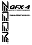
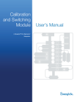
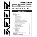
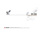
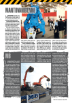
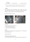
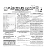
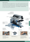
P-30
Micropipette Puller
Operation
Operation Manual
Rev. 4.00 ( 20130418)
One Digital Drive
Novato, CA 94949
Voice: 415-883-0128 Web: www.sutter.com
Fax: 415-883-0572 Email: [email protected]
ii
Copyright © 2013 Sutter Instrument Company. All Rights Reserved.
Flaming/Brown™ is a trademark of Sutter Instrument Company.
P-30 MICROPIPETTE PULLER OPERATION MANUAL – REV. 4.00 (20130418)
iii
DISCLAIMER
The pipette puller Model P-30 is designed for the specific use of creating micropipettes and no
other use is recommended.
This instrument creates items that for use only on animal tissues within a laboratory
environment. It is not intended for use, nor should be used, in human experimentation, or
applied to humans in any way. This is not a medical device.
Do not open or attempt to repair the instrument without expressed and explicit instructions
from Sutter Instrument Company. Extreme heat and high voltages are present and could
cause injury.
Do not allow unauthorized and or untrained operatives to use this device.
Any misuse will be the sole responsibility of the user/owner and Sutter Instruments assumes
no implied or inferred liability for direct or consequential damages from this instrument if it
is operated or used in any way other than for which it is designed.
SAFETY WARNINGS AND PRECAUTIONS
Electrical
Operate the P-30 using 110-120 V AC, 60 Hz, or 220-240 V AC., 50 Hz line voltage. This
instrument is designed for connection to a standard laboratory power outlet (Overvoltage
Category II), and because it is a microprocessor--controlled device, it should be accorded
the same system wiring precautions as any 'computer type' system. A surge protector and
power regulator are recommended.
Replace fuse only with the same type and rating as indicated in the following table.
Mains Voltage
Setting
Fuse
(Type: Time Delay, 5mm x 20mm, glass tube)
Rating
“110”
(100 – 120 VAC)
2A, 250V
(Time Delay)
Manufacturer Examples
Bussmann: GMC-2A, GMC-2-R (RoHS), GDC2A, or S506-2A (RoHS)
Littelfuse: 239 002 or 239.002.P (RoHS)
“220”
(200 – 240 VAC)
T1.25A,
250V
Bussmann: GDC-1.25A or S506-1.25R (RoHS)
Littelfuse: 218 1.25 or 218 1.25P (RoHS)
A spare fuse is located in the power input module. Please refer to the fusefuse-replacement
appendix for more details on fuse ratings and for instructions on how to change the fuse.
Avoiding Electrical Shock
Shock and FireFire-related Injury
Always use the grounded power supply cord set provided to connect the system to a
grounded outlet (3-prong). This is required to protect the user from injury in the event
that an electrical hazard occurs.
Do not disassemble the system. Refer servicing to qualified personnel.
To prevent fire or shock hazard do not expose the unit to rain or moisture.
P-30 MICROPIPETTE PULLER OPERATION MANUAL – REV. 4.00 (20130418)
iv
Operational
Failure to comply with any of the following precautions may damage this device.
Operate this unit using the indicated line voltage.
This unit is designed for operation in a laboratory environment (Pollution Degree II) and
at temperatures between 5°C - 40°C.
This unit is designed for connection to a standard laboratory power outlet (overvoltage
Category II) with main supply voltage fluctuations not to exceed ± 10% of the normal
voltage.
This unit is not designed for operation, nor has it been tested for safety, at altitudes above
2000 meters (6562 feet).
This unit was designed to operate at maximum relative humidity of 80% for temperatures
up to 31°C decreasing linearly to 50% relative humidity at 40°C.
Operate only in a location where there is a free flow of fresh air on all sides. The fan
draws air in through the vents on the sides and exhausts out both ends of the heat sink.
NEVER ALLOW THE FREE FLOW OF AIR TO BE RESTRICTED.
To avoid burns, do not touch the heating filament, the brass clamps holding the
filament, or the heated ends of recently pulled glass pipettes.
Only use Sutter Instrument Company replacement heating filaments.
Handling Micropipettes
Failure to comply with any of the following precautions may result in injury to the users
near
ar the device.
of this device as well as those working in the general area ne
The micropipettes created using this instrument are very sharp and relatively fragile.
Avoid contact with the tip of a pulled micropipette to prevent accidentally impaling
oneself.
Always dispose of micropipettes by placing them into a well-marked, spill-proof “sharps”
container.
Use only with capillary glass (tubing) recommended by Sutter Instrument.
P-30 MICROPIPETTE PULLER OPERATION MANUAL – REV. 4.00 (20130418)
v
TABLE OF CONTENTS
DISCLAIMER ................................................................
................................................................................................
................................................................................................
......................................................................
......................................iii
......iii
SAFETY WARNINGS AND PRECAUTIONS................................
PRECAUTIONS................................................................
...................................................................................
...................................................iii
...................iii
Electrical .................................................................................................................................................iii
Avoiding Electrical Shock and Fire-related Injury.............................................................................iii
Operational .............................................................................................................................................iv
Handling Micropipettes.........................................................................................................................iv
1. GENERAL
GENERAL................................
NERAL................................................................
................................................................................................
................................................................................................
.........................................................................
.........................................1
......... 1
1.1 Technical Support.............................................................................................................................1
1.2 Glass Capillary & Heating Filament Specifications......................................................................1
1.3 Packing List.......................................................................................................................................2
1.4 Front Panel Components.................................................................................................................2
1.4.1 Lower Panel Controls and Indicators ......................................................................................2
1.5 Front Panel Upper Right Side Controls.........................................................................................3
1.5.1 Electromechanical Slide Assembly and Controls ...................................................................4
1.5.2 Pull Solenoid...............................................................................................................................7
1.5.3 Patch Block (Figure 1-3)............................................................................................................7
2. INSTALLATION ................................................................
................................................................................................
..............................................................................................
..............................................................9
.............................. 9
2.1 Line Power (Mains) ..........................................................................................................................9
3. OPERATIONS ................................................................
................................................................................................
................................................................................................
................................................................11
................................ 11
3.1 First Time Use ................................................................................................................................11
3.2 General Operation ..........................................................................................................................11
3.3 Pulling a Micropipette ....................................................................................................................11
3.4 Multicycle Pulls: Pulling a Patch-Type Micropipette .................................................................12
3.4.1 Heat Settings ............................................................................................................................12
3.4.2 Pull Setting ...............................................................................................................................12
3.4.3 Trip Point Micrometer ............................................................................................................13
3.4.4 Patch Block (spacer) ................................................................................................................13
3.5 Patch Pipette Pull Sequence..........................................................................................................13
3.5.1 First cycle ..................................................................................................................................13
3.5.2 Second cycle ..............................................................................................................................13
3.6 Controls Adjustment ......................................................................................................................13
4. GLASS SELECTION AND SETTINGS................................
SETTINGS................................................................
........................................................................................
........................................................15
........................ 15
4.1 P-30/P Settings Sheet.....................................................................................................................15
4.1.1 Microelectrodes and Microinjection Pipettes........................................................................15
4.1.2 Patch Type Pipettes.................................................................................................................15
4.2 P-30/N Settings Sheet ....................................................................................................................16
4.2.1 Microelectrodes and Microinjection Pipettes........................................................................16
4.2.2 Patch Type Pipettes.................................................................................................................16
4.3 P-30/N with P30N-4 Filament Settings Sheet.............................................................................17
4.3.1 Microelectrodes and Microinjection Pipettes........................................................................17
4.3.2 Patch Type Pipettes.................................................................................................................17
5. MAINTENANCE ................................................................
................................................................................................
............................................................................................
............................................................19
............................ 19
P-30 MICROPIPETTE PULLER OPERATION MANUAL – REV. 4.00 (20130418)
vi
5.1 Filament Replacement ...................................................................................................................19
5.2 Lubrication ......................................................................................................................................20
5.3 Rubber Pads on Clamps .................................................................................................................20
6. TROUBLESHOOTING................................
TROUBLESHOOTING ................................................................
................................................................................................
..................................................................................
..................................................21
.................. 21
APPENDIX A. LIMITED WARRANTY................................
WARRANTY ................................................................
............................................................................................
............................................................23
............................ 23
APPENDIX B. ACCESSORIES ................................................................
................................................................................................
.........................................................................
.........................................25
......... 25
B.1. Replacement Filaments................................................................................................................25
B.1.1 Platinum/Iridium Filaments ..................................................................................................25
B.1.1 Nichrome Filaments................................................................................................................25
APPENDIX C. FUSE REPLACEMENT................................
REPLACEMENT................................................................
...........................................................................................
...........................................................27
........................... 27
APPENDIX D.
D. TECHNICAL SPECIFICATIONS ................................................................
...........................................................................
...........................................29
........... 29
INDEX ................................................................
................................................................................................
................................................................................................
.................................................................................
.................................................31
................. 31
TABLE OF FIGURES
Figure 1-1. Front panel components. ....................................................................................................... 3
Figure 1-2. Puller electromechanical slide assembly with glass clamps and filament mounting
detail........................................................................................................................................... 6
Figure 1-3. Patch block placement. .......................................................................................................... 7
Figure 2-1. P-30 cabinet (rear view). ........................................................................................................ 9
Figure 5-1. Top view of platinum filament glass and locations of Filament Plate Adjustment
screws.......................................................................................................................................19
Figure C-1. Fuse holder............................................................................................................................27
TABLE OF TABLES
Table 6-1. Troubleshooting......................................................................................................................21
Table 6-2. Mains fuse type and ratings. .................................................................................................27
Table 6-3. Mains fuse type and ratings. .................................................................................................29
P-30 MICROPIPETTE PULLER OPERATION MANUAL – REV. 4.00 (20130418)
1
1. GENERAL
The P-30 Micropipette Puller is a derivative of a vertical puller design initially developed at
the National Institutes of Health in the late 1950’s. The P-30’s design provides a basic,
economical, and simple way in which to operate the puller for those investigations where tip
diameters down to 0.3 micron and moderate taper lengths are satisfactory. Despite its low
cost, the P-30’s design provides a number of quality and convenience features. The power
supplies for the filament and pull solenoid are constant current and thermally protected.
Dual settings for heat allow for multi-step pipette fabrications such as are used in patch
clamp investigations. The front cover completely encloses the pulling mechanism to prevent
erratic results caused by drafts; and the front panel is sloped to prevent broken capillaries
from entering the solenoid area. In addition, the P-30’s circuitry incorporates CMOS logic
throughout for its high noise immunity and low power consumption.
This manual, though brief, describes all that is necessary to know to operate the P-30. The
following pages provide descriptions of the mechanical assembly, controls, and displays along
with basic information on using the puller. The P-30 provides a consistent, reproducible
environment for the manufacture of micropipettes. Its successful use will depend on
providing the minimal maintenance detailed on the following pages, information on desirable
pulling conditions obtained from colleagues and the literature; and finally, from one’s own
experience and experimentation.
This manual refers throughout to the size of the glass tubing used to pull micropipettes. The
convention used here for describing the outside diameter (O.D.) and inside diameter (I.D.) is
as follows: O.D. x I.D. These dimensions are always in millimeters (mm).
1.1 Technical Support
Unlimited technical support is provided by Sutter Instrument Company at no charge to our
customers. Our technical support staff is available between the hours of 8:00 AM and 5:00
PM (Pacific Standard Time) at (415)
(415) 883883-0128.
0128 Send E-mail queries to [email protected].
[email protected]
1.2 Glass Capillary & Heating Filament Specifications
The P-30 micropipette puller is designed for use with borosilicate, aluminosilicate or other
lower melting-point glass tubing or rod ranging from 1.0mm to 2.0mm in diameter. This
instrument does not pull fused silica or quartz glassware. The full selection of glassware
available from Sutter Instrument is listed in the catalogue included with this instrument or
can be found on the Sutter Instrument’s web site www.sutter.com.
www.sutter.com
This instrument can accommodate either one of two nichrome wire filaments or trough-type
platinum filament, as shown in the Sutter Catalogue. A list of replacement filaments for the
P-30 exists on Sutter Instrument’s web site (www.sutter.com)
www.sutter.com).
www.sutter.com) USE ONLY SUTTER
INSTRUMENT--SUPPLIED REPLACEMENT HEATING FILAMENTS IN THIS
INSTRUMENT! Instructions for replacing the Heating Filament are in the Maintenance
section of this manual.
P-30 MICROPIPETTE PULLER OPERATION MANUAL – REV. 4.00 (20130418)
2
1.3 Packing List
Make certain that all of the following items are in the P-30’s shipping box received:
P-30 micropipette puller
Power cord
Box of sample glass
3 (P(P-30/P) or 1 (P(P-30/N) spare
spare heating filaments
Patch Block attachment
Warranty registration
Catalog
The Model P-30 is shipped a prefabricated foam mold. Please take note of this method of
packaging. If it is ever necessary to ship the puller to another location, be sure to use the
same packaging method. Additional packing material is available for purchase from Sutter
Instrument.
IMPORTANT: Improper packaging is a form of abuse and, as such, can be responsible for
voiding the warranty where shipping damage occurs because of such packing.
1.4 Front Panel Components
The front panel consists of controls and indicators, plus the electromechanical device that
physically mounts, heats, and pulls the glass into micropipettes. These controls apply power
to the instrument, set heat values, pull strength value, and start and stop pulling sequences.
Descriptions of the individual components of the front panel presented below begin with the
lower portion, followed by those on the upper right, and conclude with the electromechanical
pull assembly, solenoid, and patch block.
1.4.1 Lower Panel Controls and Indicators
Power Switch
This toggle switch’s ON position applies power to the instrument. The
Switch
red lamp indicator illuminates when power is on.
RESET Switch
This switch resets the circuitry to an initialized condition. Its typical use
is to turn off the heat during multi-step fabrications (patch type
pipettes).
Power
Power Indicator
This indicator lights up when the power switch is in the ON position.
PULL Switch
This switch initiates the pulling process.
P-30 MICROPIPETTE PULLER OPERATION MANUAL – REV. 4.00 (20130418)
3
Figure 1-1. Front panel components.
1.5 Front Panel Upper Right Side Controls
Heat 1/Heat 2 switch
This switch determines which of the two heat values is active.
HEAT 1 control
HEAT 1 is a three-digit pushbutton control used to set the level of
electrical current supplied to the filament. The HEAT required to
melt a piece of glass is a function of the filament installed and the
particular glass size and composition. Maximum current available is
22.5 amperes
HEAT 2 control
control
Sets a second level of electrical current supplied to the filament.
PULL Strength
control
A three-digit pushbutton control used to set the level of electrical
current supplied to the pull solenoid. This parameter controls the
force of the hard pull. Generally, the stronger the pull, the smaller
the pipette’s tip diameter, and the longer it’s taper.
P-30 MICROPIPETTE PULLER OPERATION MANUAL – REV. 4.00 (20130418)
4
1.5.1 Electromechanical Slide Assembly and Controls
The following names and describes the various parts of the electromechanical pull system.
Knowing the names of the various parts greatly facilitates communication between the
investigators and the manufacturer when discussing adjustments or service issues. The
descriptions directly relate to the designations shown in Figure 1-2.
A Upper (Stationary) Glass Clamp Assembly : This assembly clamps one end of the capillary glass
above the filament. I is loosened for repositioning the glass when doing multi-step pulling.
B Filament Assembly :
P-30/P: Platinum/iridium trough shaped foil filament P30P. The P30P mounting assembly
consists of two brass-clamping blocks and two Phillips-head screws that secure the filament
between spring-loaded clamps.
C
D
E
F
G
H
I
J
K
L
P-30/N: Nichrome 3-coil (P30N) or 4-coil (P30N-4) filament: The P30N-series mounting
assembly consists of two brass bus bars and posts for conducting electrical current through
the filament, with brass thumbscrews to secure the filament to the conducting posts.
Lower (Moving)
(Moving) Glass Clamp Assembly:
Assembly: Clamps the lower end of the glass capillary, and is
attached to the upper end of the slide bar.
Slide Bar : The slide bar is a hardened steel tube that guides the descent of the lower glass
clamp during a pull. The bar’s weight and attachments provide the pulling force used during
the initial(gravity) phase of pulling.
Bushing Blocks
Blocks and Guide Bushings:
Bushings The bushing blocks contain the precision linear guide
bearings that form the descent path for the slide bar.
Trip Flag Holder: The trip flag holder is held in place on the slide bar by a thumb screw, its
position being dependent on the type of pipette being pulled. The trip flag extends to the left of
the slide mechanism so that it may interrupt the light path of the optical switch, which is
located on the end of the trip point micrometer.
Guide Flag Holder:The
guide flag holder is attached to the lower end of the slide bar. The
Holder
attached flag extends back into a slot in the cabinet and serves to prevent rotation of the slide
bar and associated parts during a pull. The guide flag holder is also the point of attachement for
the cable that connects to the pull solenoid.
Trip Point Adjustment Micrometer Control:
Control A micrometer with 0.001-inch divisions used for
precision positioning of the optical switch that determines the distance to which the glass draws
out before initiating a hard pull.
Filament Plate Adjusting Screws:The
hexagonal-head adjusting screws move the filament
Screws:
mounting plate horizontally towards or away from the vertical glass. Adjust both screws at the
same rate to ensure that the filament is perfectly vertically parallel to the glass. If using a
slightly distorted filament, turn the top and bottom screws at different rates to ensure that the
top and bottom of the filament are equidistant from the glass.
Trip Point Optical Switch:Cconsists
of a light path emitted by an LED and picked up by an
Switch
optical sensor. Blocking the light path with the Trip Point Flag, initiates a hard pull.
Hard Pull Cable:
Cable The top end of this cable attaches to the Guide Flag Holder (G); the bottom
end connects with the hard pull solenoid inside the cabinet. For types of pipettes that do not
require a hard pull, disconnect the top end of the cable.
Glass Clamp Thumb Control: The upper and lower glass clamp assemblies each consists of a
thumbscrew used to tighten or loosen each glass clamp. Padding is adhered to the surface of the
thumbscrew’s rectangular block that makes contact with the glass.
P-30 MICROPIPETTE PULLER OPERATION MANUAL – REV. 4.00 (20130418)
5
Figure 1-2. Puller electromechanical slide assembly with glass clamps and filament mounting detail.
P-30 MICROPIPETTE PULLER OPERATION MANUAL – REV. 4.00 (20130418)
6
1.5.2 Pull Solenoid
The pull solenoid (located just below the slide assembly in the angled portion of the cabinet)
is responsible for accelerating the slide bar during the second (solenoid) phase of pipette
formation. Interrupting the optical switch with the trip flag energizes the solenoid.
1.5.3 Patch Block (Figure
(Figure 1-3)
The patch block is a metal block with screws on the top and bottom sides. The patch block
provides two adjustable spacers used in forming patch pipettes.
Figure 1-3. Patch block placement.
P-30 MICROPIPETTE PULLER OPERATION MANUAL – REV. 4.00 (20130418)
7
2. INSTALLATIO N
2.1 Line Power (Mains)
The power cord provided with the P-30 connects to the power entry module located on the
back of the unit (see diagram below). This module also includes the line fuse.
Figure 2-1. P-30 cabinet (rear view).
Confirm that the Voltage Selector Switch on the Power Entry Module is set to the proper
value (110V a.c. or 220V a.c.). If it is not, turn the selector switch until the
the appropriate value
lines up with the indicator. Note that the fuse differs for the two different line voltages (see
the Technical Specifications).
Specifications). If changing the voltage selector, also change the fuse to one
specified for the selected voltage. Failure to use the correct fuse for the voltage selected may
compromise protection from fire and electric shock.
Make certain that the power switch located on the front panel of the P-30 cabinet is in the
OFF position. Plug the power cord provided with the P-30 into the Line Input socket on the
Power Entry Module located on the rear of the cabinet and then to a power source of the
appropriate voltage and frequency.
P-30 MICROPIPETTE PULLER OPERATION MANUAL – REV. 4.00 (20130418)
8
(This page intentionally left blank.)
P-30 MICROPIPETTE PULLER OPERATION MANUAL – REV. 4.00 (20130418)
9
3. OPERATIONS
3.1 First Time Use
Use
1. Load a piece of the supplied sample glass into puller as follows:
• Loosen the upper and lower clamping knobs.
• Place glass in V-groove in upper clamp; slide it downward until about 1 cm of glass
extends above the top clamp. Tighten upper clamp
• Pull lower clamp up until it no longer moves and tighten clamping knob.
2. Press the PULL button. The heating filament should turn on and the glass should
separate within 15 seconds.
3.2 General Operation
The P-30 is quite simple to operate. However, common sense indicates that using an
instrument that can melt glass must include some caution and a complete understanding of
its controls. Do not leave the puller powered on and unattended, particularly while a pullsequence is in progress. Pay extra attention when pulling pipettes after any control values
are changed.
The following steps outline a basic pulling sequence. The pulling process is hypothetical
(with respect to the settings mentioned) – it is only an example of the normal pulling
procedure. The pipette shapes and tip diameter obtained from a puller of this type are
dependent on the rate at which heat is added to the glass (rate of change of viscosity), weight
of the moving portion of the slide assembly, distance traveled during gravity pull phase, and
force of solenoid pull. After finding settings that produce the desired pipette, make note of
the time it takes for the pull to take place and the distance traveled before the hard pull. The
time for a pull is most important, particularly when having to install a new filament. No two
filaments are exactly alike with respect to their resistance; thus, the heat setting may not be
the same for two different filaments to supply the same amount of heat. All other factors
being unchanged (pull strength, glass size, acceleration due to gravity, etc.), if adjusting the
heat output of the new filament to produce a pull in the same amount of time as the previous
filament, the resulting pipettes should be equivalent.
3.3 Pulling a Micropipette
Turn the instrument on, and make sure to select the desired heat value. When setting a heat
value for the first time, press the PULL switch (without glass in puller) and increase the
HEAT control while watching the filament. If using a platinum filament, be sure the heat
value is initially set at a low value (e.g. 300 for a 1.5mm filament, 650 for a 3.0mm filament).
High heat values can destroy the platinum filaments. Because of the time constant of the
nichrome filament, allow a few moments to pass after making any changes to let the filament
stabilize at the new heat setting (e.g., 760 for P30N-4 filament (4 turns) or 990 for P30N (3
P-30 MICROPIPETTE PULLER OPERATION MANUAL – REV. 4.00 (20130418)
10
turns))1. When the filament glows at desired heat level, note the selected value. Press RESET
to turn off filament.
Open upper glass clamp and insert glass capillary into the jaws. Close down clamp on
capillary until lightly gripping the glass so it can still slide. Slide capillary down through
filament to the point where raising the lower glass clamp can grip lower end of capillary.
Tighten upper clamp and raise lower clamp over capillary. As glass capillaries may have a
slight curve to them, take care when inserting the capillary into the lower jaws. Tighten
lower glass clamp. The setting of the trip point is an important determinant of the resultant
size and shape (covered next). Close front door and press PULL.
The following sequence takes place:
1. Filament turns on, heating the glass to a softening point.
2. As the glass softens, the lower glass clamp and slide bar descent under the influence of
gravity until the trip flag interrupts the optical switch.
3. The optical switch deactivates the heat and activates the pull solenoid for approximately
one second to complete pull.
Remove lower and upper pipettes.
3.4 Multicycle Pulls
Pulls: Pulling a PatchPatch-Type Micropipette
Patch type pipettes are characteristically stubby with a large taper angle and relatively large
tips (> 1 micron). To construct this type of pipette, it is desirable to process the glass in
multiple heating cycles. When using the P-30 for two-step pipette fabrication, use of the dual
heat settings and the supplied Patch Block. The first of the two steps draws the glass out
without separating. In the second step, manually reposition the glass tube to center the
drawn-out portion within the heating element. The second-step pull draws the glass out until
it separates to form a pipette.
3.4.1 Heat Settings
HEAT 1 is used for the first step, and is generally set at a fairly high level (e.g. 800 for 3mm
platinum filament, 980 for P30N three-coil filament, or 800 for P30N-4 four-coil filament).
Use HEAT 2 for the second step, after the first pull of the glass. HEAT 2 is normally less, and
is more critical, than HEAT 1. The exact values for a particular application will have to be
determined on a trail and error basis.
3.4.2 Pull Setting
Pull is normally set to zero for patch pipettes because the weight of the sliding components
provides the force that draws out the glass. If desired, disconnect the solenoid plunger from
the slide assembly by loosening the setscrew that attaches the cable to the slide flag holder.
Disconnecting the cable decreases the weight by about 20%.
3.4.3 Trip Point Micrometer
The micrometer should be advanced so that the flag does not interrupt the optical switch
until the second step is complete. Because the solenoid is generally not used in forming patch
1
There are two versions of the nichrome filament: One with three turns and larger I.D. (P30N), requiring heat levels of 980-990; and the other
one with four turns and a smaller I.D. (P30N-4, requiring heat levels between 700-850.
P-30 MICROPIPETTE PULLER OPERATION MANUAL – REV. 4.00 (20130418)
11
pipettes, the trip point system serves primarily as a means of turning off the heat. While it is
easy to reposition the trip point for each step, it is generally more convenient to use the
RESET button to turn the heat off after the first step. Thus, the optical switch will normally
be placed so that the flag passes through the switch in the second step. This will cause the
heat to turn off automatically at the end of the second step.
3.4.4 Patch
Patch Block (spacer)
The two screws on the Patch Block allow for the block can act as two adjustable spacers. The
10/32 cap head screws supplied accept a 5/32 hex key wrench; the thumbnuts are used to lock
the screws in position. The thumbnuts are different colors allowing differentiation between
Spacer 1 and Spacer 2. One spacer limits the draw of the first pull cycle. The second spacer
repositions the glass within the heating filament prior to pulling the glass apart in the second
step. The position of the two screws in the Patch Block will need to be determined
empirically.
3.5 Patch Pipette Pull Sequence
3.5.1 First cycle
Set the HEAT switch to HEAT 1 and load capillary. Place the Patch Block so that is sits on
the top of the bearing block and behind the slide bar as show in Figure 1-3. The head of the
screw will act to stop the slide mechanism by hitting the underside of the lower slide. The
length of the first pull is determined by the space between the top of the Patch Block screw
and the bottom of the lower glass clamp assembly. Press PULL, wait until the slide drops
onto the screw, and then press RESET. Remove Patch Block.
3.5.2 Second cycle
Since the heating filament is fixed in position and the glass is drawn in one direction, it
follows that the portion of the glass that has been reduced in size will not be centered in the
filament at the end of the first step. Reposition the glass by first loosening the upper glass
clamp, lifting the lower slide assembly until re-centering the glass within the filament, and
then retightening the upper clamp. For consistent results when re-centering the glass, insert
the Patch Block (second screw) between the top of the bearing block and the bottom of the
lower glass clamp. Tighten the upper glass clamp while the lower glass clamp rests on the
head of the screw. Remove the Patch Block. Set the HEAT switch to HEAT 2, and press
PULL. The pipette should separate during this cycle, and the heat will automatically turn off.
3.6 Controls Adjustment
In order to make pipettes with desired specifications, it is important to understand the
effects of the controls and the various parameters of the glass. The general rule-of-thumb is
that both an increase in the heat and an increase in the pull strength will produce smaller
tips and longer tapers. Thus, to obtain the smallest possible tips, use a high heat setting (e.g.
980 for P30N nichrome filament, 850 for P30N-4 filament, and 750 for 3mm platinum
filament), and a pull setting above 500.
The setting of the optical switch is more complicated. The P-30 optical switch was set at 2.5
for P30P or 4.5 for P30N to produce fine micropipettes with 1mm O.D. x .5mm I.D.
borosilicate glass when shipped from the factory. As the optical switch is moved lower, the
P-30 MICROPIPETTE PULLER OPERATION MANUAL – REV. 4.00 (20130418)
12
distance travelled in the weak pull will increase. The longer the weak pull, the more the glass
is attenuated in diameter. This will influence the rate at which the glass can be drawn-out
during the subsequent hard pull as well as the rate of cooling during that pull. In addition,
the length of the weak pull will determine the position of the solenoid plunger in the solenoid
coil, which in turn will alter the force developed by the solenoid. It follows that some trial
and error adjustment of the optical switch may be required to obtain a particular result. If
the weak pull is too short, the resulting tips will be quite large. If the weak pull is too long,
the resulting pipettes may form long wispy threads rather than tips.
P-30 MICROPIPETTE PULLER OPERATION MANUAL – REV. 4.00 (20130418)
13
4. GLASS SELECTION AND SETTINGS
4.1 P-30/P Settings Sheet
For a 3mm Platinum Trough Filament (P30T30), the following settings are recommended:
4.1.1 Microelectrodes and Microinjection Pipettes
Glass
1.0 x 0.50 mm (BF100-50-10)
1.0 x 0.78 mm (BF100-78-10)
1.2 x 0.60 mm (BF120-60-10)
1.2 x 0.94 mm (BF120-94-10)
1.5 x 0.86 mm (BF150-86-10)
1.5 x 1.10 mm (BF150-110-10)
Heat #1
Pull
Optical Micrometer Setting
760-780
760-780
760-780
760-780
800-820
790-820
200-700
400-700
200-700
400-700
200-700
400-700
2.5 - 3.0
2.5 - 3.0
2.5 - 3.0
2.5 - 3.0
2.5 - 3.0
2.5 - 3.0
CAUTION: AVOIDING
AVOIDING HEAT SETTINGS OVER 850 UNITS MINIMIZES THE RISK OF
BURNING OUT THE FILAMENT.
For short tapers (4-6mm) and tips around 1µm, start with the lower heat and pull settings.
For a tip larger than 1µm, use a Pull of <000> and a HEAT setting between 720 and 760.
Higher micrometer settings (3-5) will cause the heat to turn off earlier.
For longer tapers (6-9mm) and smaller tips (0.7-0.3 microns), start with higher heat and pull
settings. Lower micrometer settings (between 0 and 2) will allow the heat to stay on longer.
For smaller tips under 0.5µm, it is best to use a heat between 800-780, an optical switch
micrometer setting of 2.5, and a pull setting between 700 and 999.
4.1.2 Patch Type Pipettes
Making a patch pipette with a short 3-4 mm taper and a 2-3 µm ID tip is not possible using a
vertical puller. Please use a P-97 or P-1000 Pipette Puller for making short tapered patch
pipettes. However, it is possible to produce a pipette for slice patch recording that normally
requires a slightly longer 4-6 mm taper and 1-2 µm tip. When using thick-walled glass to
make patch pipettes (1.5 x 0.86, 1.2 x 0.60, and 1.0 x 0.50), it is necessary to use the patch
block (included) to manually perform a two-stage pull where high and low heat settings are
used (Heat #1 & Heat #2). Consider also removing the pull solenoid weight attached to the
lower carriage to create larger tips openings. Refer to the instructions on performing a twostage pull covered earlier in this manual.
To create a short taper and a 1-2 µm tip with a one-stage pull, use the following glass &
settings:
Glass:
1.65 x 1.20 mm (BF165-120-10),
1.5 x 1.17 mm (BF150-117-10),
1.5 x 1.10 mm (BF150-110-10),
1.2 x 0.94 mm (BF120-94-10), or
1.0 x 0.78 mm (BF100-78-10)
Settings: Heat = 760;
Pull = 0; and
Micrometer = 2.5 – 3.0.
Adjust the heat setting so the glass separates in 6-12 seconds. Higher heat settings allow for
smaller tips, while a lower heat setting allows for larger tips. If the heat is set too low, the
glass will not melt. If the micrometer setting for the optical switch is set too high, the glass
will not separate.
P-30 MICROPIPETTE PULLER OPERATION MANUAL – REV. 4.00 (20130418)
14
4.2 P-30/N Settings Sheet
For the Nichrome Coil Filament (P30N),
(P30N) the following settings are recommended
4.2.1 Microelectrodes and Microinjection
Microinjection Pipettes
Glass
1.0 x 0.50 mm (BF100-50-10)
1.0 x 0.78 mm (BF100-78-10)
1.2 x 0.60 mm (BF120-60-10)
1.2 x 0.94 mm (BF120-94-10)
1.5 x 0.86 mm (BF150-86-10)
1.5 x 1.10 mm (BF150-110-10)
Heat #1
Pull
Optical Micrometer Setting
980
970
980
970
990
980
300-600
300-600
300-600
300-600
300-600
300-600
2.5 - 3.0
2.5 - 3.0
2.5 - 3.0
2.5 - 3.0
2.5 - 4.0
2.5 - 4.0
For short tapers (4-6mm) and tips around 1µm, start with the lower Heat and Pull settings.
For a tip larger than 1µm, use a Pull of <000> and a HEAT setting between 960 and 970.
Higher micrometer settings (3-5) will cause the heat to turn off earlier.
For longer tapers (6-9mm) and smaller tips (0.7-0.3 microns), start with higher Heat and Pull
settings. Lower micrometer settings (between 0 and 2) will allow the heat to stay on longer.
For smaller tips under 0.5µm, it is best to use a Heat between 990-999, an optical switch
micrometer setting of 2.5, and a Pull setting between 700 and 999.
For long tapers (1 to 1.5cm), use Heat settings between 990-999, a Pull of <000>, and optical
micrometer settings between 2 and 0.
For VERY long tapers or for Aluminosilicate Glass, purchase the P30N-4 filament (which is a
longer Nichrome filament with 4 turns that wraps closely around the glass and provides
higher heat). For recommended settings, please refer to the P-30/N with P30N-4 Filament
Settings Sheet presented next.
4.2.2 Patch Type Pipettes
Making a patch pipette with a short 3-4 mm taper and a 2-3 µm ID tip is not possible using a
vertical puller. Please use a P-97 or P-1000 Pipette Puller for making short tapered patch
pipettes. On the other hand, it is possible to produce a pipette for slice patch recording,
normally requiring a slightly longer 4-6mm taper and a 1-2 µm tip. For those using thickwalled glass (1.5 x 0.86, 1.2 x 0.60, and 1.0 x 0.50) to make patch pipettes, a manual two-stage
pull using the included patch block is necessary. Consider also removing the pull solenoid
weight attached to the lower carriage to create larger tip openings. Please refer to the end of
the Operations chapter for instructions on performing a two-stage pull.
To create a short taper and a 1-2µm tip with a one stage pull, the following glass & settings
are recommended:
Glass:
1.65 x 1.20 mm (BF165-120-10), 1.5 x 1.17 mm (BF150-117-10),
1.5 x 1.10 mm (BF150-110-10),
1.2 x 0.94 mm (BF120-94-10), or
1.0 x 0.78 mm (BF100-78-10)
Settings: Heat = 960-980;
Pull = 0; and
Micrometer = 3.5 – 4.5.
Adjust the heat setting so the glass separates in 10-15 seconds. If the heat is set too low, the
glass will not melt. If the micrometer setting for the optical switch is set too high, the glass
will not separate.
P-30 MICROPIPETTE PULLER OPERATION MANUAL – REV. 4.00 (20130418)
15
4.3 P-30/N with P30NP30N-4 Filament Settings Sheet
Using the Nichrome 4-Turn Coil Filament (P30N(P30N-4), the following settings are recommended
4.3.1 Microelectrodes and Microinjection Pipettes
1.0mm x 0.50mm
1.0mm x 0.78mm
1.2mm x 0.60mm
1.2mm x 0.94mm
1.5mm x 0.86mm
1.5mm x 1.10mm
Glass
Heat #1
Pull
Micrometer Setting
(BF100-50-10)
(BF100-78-10)
(BF120-60-10)
(BF120-94-10)
(BF150-86-10)
(BF150-110-10)
760-780
750-770
760-780
750-770
780-800
780-800
300-600
500-700
300-600
500-700
300-600
500-700
4-5
3-4
4-5
3-4
4-5
3-4
For short tapers (4-6mm) and tips around 1µm, start with the lower Heat and Pull settings.
For a tip larger than 1µm, use a Pull of <000> and a HEAT setting between 720 and750.
Higher micrometer settings (3-5) will cause the heat to turn off earlier.
For longer tapers (6-9mm) and smaller tips (0.7-0.3 microns), start with higher Heat and Pull
settings. Lower micrometer settings (between 0 and 2) will allow the heat to stay on longer.
For smaller tips under 0.5µm, it is best to use a Heat between 780-800, an optical switch
micrometer setting of 4.5, and a Pull setting between 700 and 999.
For VERY long tapers (2 to 3cm), use Heat settings between 850-900, a Pull of <000>, and
optical micrometer settings between 2 and 0.
For Aluminosilicate Glass (AF150-100-10, AF120-85-10, AF100-64-10, use Heat settings
between 900-950, a Pull of 300-600, and optical micrometer settings between 2 and 4.
4.3.2 Patch Type Pipettes
Making a patch pipette with a short 3-4mm taper and a 2-3µm ID tip is not possible using a
vertical puller. Please use a P-97 or P-1000 Pipette Puller for making short tapered patch
pipettes. On the other hand, it is possible to produce a pipette for slice patch recording,
normally requiring a slightly longer 4-6mm taper and a 1-2µm tip. For those using thickwalled glass (1.5 x 0.86, 1.2 x 0.60, and 1.0 x 0.50) to make patch pipettes, a manual two-stage
pull using the included patch block is necessary. Consider also removing the pull solenoid
weight attached to the lower carriage to create larger tip openings. Please refer to the P-30/N
User’s Manual for instructions on performing a two-stage pull.
To create a short taper and a 1-2µm tip with a one-stage pull, use the following glass &
settings:
Glass:
1.65 x 1.20 mm (BF165-120-10), 1.5 x 1.17 mm (BF150-117-10),
1.5 x 1.10 mm (BF150-110-10),
1.2 x 0.94 mm (BF120-94-10), or
1.0 x 0.78 mm (BF100-78-10)
Settings:
Heat = 680-720;
Pull = 0; and
Micrometer = 3.5 – 4.5.
Adjust the heat setting so the glass separates in 6-12 seconds. Higher heat settings will allow
for smaller tips, lower heat setting will allow for larger tips. If the heat is set too low, the
glass will not melt. If the micrometer setting for the optical switch is set too high, the glass
will not separate.
P-30 MICROPIPETTE PULLER OPERATION MANUAL – REV. 4.00 (20130418)
16
(This page intentionally left blank.)
P-30 MICROPIPETTE PULLER OPERATION MANUAL – REV. 4.00 (20130418)
17
5. MAINTENANCE
5.1 Filament Replacement
Platinum filament life will vary with several factors; operation temperature, frequency of
use, and the amount of care taken to avoid damage. Filament deterioration becomes more
rapid at higher operating temperatures, so it is good practice to keep the heating current as
low as possible, consistent with forming tips of the desired size and configuration. Significant
deterioration of the filament is indicated by the appearance of small holes. These holes raise
the resistance of the filament and necessitate higher HEAT setting to produce the same heat
output.
Platinum trough filaments for the P-30 are available in three widths: 1.5mm, 2.0m and
3.0mm. Heat delivery to the glass is partially a function of filament width. Thus, both the
length of an electrode and the tip diameter are affected by the filament width. A 3.0mm wide
filament will tend to produce longer pipettes and be capable of producing smaller tip
diameters. The 1.5mm wide filament will produce shorter pipette, but cannot be used to pull
as fine a tip as the wider filament.
To replace the filament, first loosen the thumbscrews that clamp the filament in place.
Remove the old filament. The sides of the new filament should be relatively parallel or
slightly less than parallel as illustrated in Figure 5-1. Grasp the new filament with a pair of
forceps and place the filament wings between the clamping jaws. Center the filament relative
to a piece of glass loaded in the upper glass clamp. Tighten the thumbnuts.
The entire heater block assembly is spring loaded to allow for adjusting the
forward/backward position of the platinum filament relative to a piece of glass. The back of
the filament should be approximately 0.5 mm to 1 mm away from the glass tubing (Figure
5-1). To move the filament forward (towards the glass), use an Allen wrench to loosen the
two hex-head screws located on the black nylon block just above and below the brass clamp
assembly. The heater assembly will slide forward on the guide pins until the screws restrict
movement. To move the filament back (away from the glass), turn the hex-head screws
clockwise an equal amount until attaining the desired filament position. A slightly distorted
filament may require that the hex-head screws be turned at different rates to ensure that the
top and bottom of the filament are equidistant from the glass.
Figure 5-1. Top view of platinum filament glass and locations of Filament Plate Adjustment screws..
P-30 MICROPIPETTE PULLER OPERATION MANUAL – REV. 4.00 (20130418)
18
For a list of replacement filaments, see Appendix B – Accessories.
5.2 Lubrication
The slide bar should occasionally be wiped down with a light oil to protect it from corrosion.
Note that materials such as 3-in-1 oil are not sutiable as they leave a residue which can
“gum-up” the slide bar and bushings.
No other P-30 components require lubrication.
5.3 Rubber Pads on Clamps
The rubber pads attached to the upper and lower glass clamps can wear down to the extent
that it becomes difficult to adequately clamp the glass in place. If this should occur, please
contact the technical support staff at Sutter and request some replacement pads. The pads
can be bonded to the clamps with cyanoacrylate (“super glue”) or a similar bonding material.
P-30 MICROPIPETTE PULLER OPERATION MANUAL – REV. 4.00 (20130418)
19
6. TROUBLESHOOTING
We have provided this section as an aid for troubleshooting some of the common electronic
problems of the P-30. Discussions of circuit board level troubleshooting and circuit board
schematics have intentionally been left out. Any work done with the cabinet cover removed
requires very careful attention to the hazardous voltages that exist inside cabinet, and should
therefore be performed by qualified service personnel only. Please contact Sutter for further
information and advice prior to removing the cabinet. Instructions and circuit schematics can
be supplied upon request.
Table 6-1. Troubleshooting.
Symptoms
Possible
Possible Causes and Solutions
Pilot light not
on, no pull or
heat
Check and make sure that the power cord is connected to a working
circuit and that the power has been switched on. If the power is good,
disconnect the power cord and check to see if the fuse on the rear of the
cabinet has blown. If the fuse is good, put it back in place and reconnect
the power. If the unit seemed to turn off during a prolonged pull, the
internal protective thermostat may have opened. The thermostat will
automatically reset if the instrument is turned off for about ½ hour. If the
fuse has blown, suspect failed power MOSFET transistor(s) in the
constant current power supplies (see below). Contact Sutter Instrument
for MOSFET replacement instructions.
Pilot light on,
no heat
If the pilot light is on, there is no need to check the fuse or power
connections, although it may be desirable to check for low line voltage. If
the heat fails to turn on when the PULL button is pressed, make sure
that there is a reasonable heat value entered and that the HEAT
1/HEAT2 switch is set to select the desired value. Check that the optical
switch is not interrupted by the flag. With no glass loaded, press PULL
and, carefully, lift the slide unit until the flag interrupts the optical
switch. This should activate the pull, which will forcefully draw the slide
bar down. If the pull is not activated, refer to (3).
If pull is working, the basic logic circuits and the power supplies are
functional. Check to make sure the thumbnuts that hold the filament in
place are tight. Inspect the filament for a possible break. If the system has
a nichrome filament assembly, check the screws that hold the binding
posts to the copper straps and the screws that secure those straps to
insure that good contact is made throughout. Further checks require
removal of the cover portion of the cabinet. Please contact the technical
support staff at Sutter if further troubleshooting is required.
P-30 MICROPIPETTE PULLER OPERATION MANUAL – REV. 4.00 (20130418)
20
Symptoms
Possible
Possible Causes and Solutions
Pilot light on,
no heat or pull
These symptoms suggest one of three faults: 1) the 40-volt power supply
has failed; 2) the 2.5-volt reference has failed; or, 3) the logic circuits fail
to correctly enable the heat and pull. To check any of these faults requires
that the cabinet be removed from the puller. Please contact Sutter prior
to troubleshooting these faults. A circuit diagram and instructions can be
supplied if necessary.
Pilot light on,
heat works, no
pull
If the heat does not turn off when the optical switch is interrupted,
suspect the optical switch. If the heat does turn off, but the pull never
turns on, the logic and constant current circuits need to be checked.
Please contact Sutter if this is required.
P-30 MICROPIPETTE PULLER OPERATION MANUAL – REV. 4.00 (20130418)
21
APPENDIX A. LIMITED WARRANTY
Sutter Instrument Company, a division of Sutter Instrument Corporation, limits the
warranty on this instrument to repair and replacement of defective components for two
years from date of shipment, provided the instrument has been operated in accordance
with the instructions outlined in this manual.
Abuse, misuse, or unauthorized repairs will void this warranty.
Warranty work will be performed only at the factory.
The cost of shipment both ways is paid for by Sutter Instrument during the first three
months this warranty is in effect, after which the cost is the responsibility of the
customer.
The limited warranty is as stated above and no implied or inferred liability for direct or
consequential damages is intended.
Consumables, PMTs, galvanometers, and Uniblitz®2 shutters are exempt from this
warranty.
An extended warranty for up to three additional years can be purchased at the time of
ordering, or until the original warranty expires. For pricing and other information, please
contact Sutter Instrument.
2
Uniblitz® is a registered trademark of Vincent Associates.
P-30 MICROPIPETTE PULLER OPERATION MANUAL – REV. 4.00 (20130418)
22
(This page intentionally blank.)
P-30 MICROPIPETTE PULLER OPERATION MANUAL – REV. 4.00 (20130418)
23
APPENDIX B. ACCESSORIES
The following accessories are available for the P-30 Micropipette Puller. See
http://www.sutter.com for more detail and availability P-30 accessories, and for part numbers
not expressed in the following list.
P-3030-NFL/M
Nichrome filament block assembly (see note)
P-3030-PFL/M
Platinum/iridium filament block assembly (see note)
PET
Pipette examining tile
CTS
Ceramic tile for scoring glass (large tips 20-200 microns)
BX10
Pipette storage box 4 3/4 x 3 5/8 x 3/4 inches
BX20
BX20
Pipette storage box - long 7 x 3 5/8 x 3/4 inches
BVBV-10
BV-10 Microelectrode Beveler
NOTE: Only necessary when changing between platinum and nichrome filaments.
B.1. Replacement Filaments
B.1.1 Platinum/Iridium
Platinum/Iridium Filaments
P30T30
3mm Trough
P30T20
2mm Trough
P30T15
P30T15
1.5mm Trough
P30T Custom
For long tapers or multibarrel glass, contact Sutter Instrument
for technical support.
B.1.1 Nichrome Filaments
P30N
Three-turn coil filament for shorter tapers.
P30NP30N-4
Four-turn coil filament for longer tapers and higher heat levels
required for aluminosilicate glass.
P-30 MICROPIPETTE PULLER OPERATION MANUAL – REV. 4.00 (20130418)
24
(This page intentionally blank.)
P-30 MICROPIPETTE PULLER OPERATION MANUAL – REV. 4.00 (20130418)
25
APPENDIX C. FUSE REPLACEMENT
In the event that the puller fails to power up when the power switch is turned on, check the
line power fuse to see if it has blown. The fuse is located in the fuse holder on the power
entry module on the back of the P-30. To remove the fuse holder first unplug the power cord
from the power entry module. This will reveal a slot just under the edge of the fuse holder.
Use a screwdriver to pry the holder straight out of the power entry module.
Figure C-1. Fuse holder.
The fuse that is readily visible when the fuse holder is removed is the one that is “active”
when the holder is installed. A spare fuse is also stored within the fuse holder (concealed in a
compartment as shown in Figure C-1). To remove the spare fuse, press down on the end of
the compartment and push it out of the other end. The old fuse can serve as a convenient tool
for pushing the spare fuse compartment out. Replace the active fuse with the spare and reinstall the fuse holder and power cord. If the P-30 fails to power up with the new fuse
installed, call Sutter Instrument technical support personnel for assistance.
Replace fuse only with the same type and rating:
Table 6-2. Mains fuse type and ratings.
Mains Voltage
Setting
Fuse
(Type: Time Delay, 5mm x 20mm, glass tube)
Rating
“110”
(100 – 120
VAC)
2A, 250V
(Time Delay)
“220”
(200 – 240
VAC)
T1.25A, 250V
Manufacturer Examples
Bussmann: GMC-2A, GMC-2-R (RoHS), GDC2A, or S506-2A (RoHS)
Littelfuse: 239 002 or 239.002.P (RoHS)
Bussmann: GDC-1.25A or S506-1.25R (RoHS)
Littelfuse: 218 1.25 or 218 1.25P (RoHS)
P-30 MICROPIPETTE PULLER OPERATION MANUAL – REV. 4.00 (20130418)
26
(This page intentionally blank.)
P-30 MICROPIPETTE PULLER OPERATION MANUAL – REV. 4.00 (20130418)
27
APPENDIX D. TECHNICAL SPECIFICATIONS
Dimensions
Dimensions (H x W x D):
18 x 10 x 9 in (46 x 25 x 23 cm)
Weight:
35 lb. (16 kg)
Electrical:
Mains voltage
110110-120 V, 60 Hz
220--240 V, 50 Hz
220
Maximum power consumption
180 VA
Mains fuse (rear of cabinet)
Table 6-3. Mains fuse type and ratings.
Mains Voltage
Setting
Fuse
(Type: Time Delay, 5mm x 20mm,
20mm, glass tube)
Rating
“110”
(100 – 120
VAC)
2A, 250V
(Time Delay)
“220”
(200 – 240
VAC)
T1.25A,
250V
Power cord
Manufacturer Examples
Bussmann: GMC-2A, GMC-2-R (RoHS), GDC-2A, or
S506-2A (RoHS)
Littelfuse: 239 002 or 239.002.P (RoHS)
Bussmann: GDC-1.25A or S506-1.25R (RoHS)
Littelfuse: 218 1.25 or 218 1.25P (RoHS)
10A, 250V, with safety ground plug
P-30 MICROPIPETTE PULLER OPERATION MANUAL – REV. 4.00 (20130418)
28
(This page intentionally left blank.)
P-30 MICROPIPETTE PULLER OPERATION MANUAL – REV. 4.00 (20130418)
29
INDEX
A
M
accessories ..............................................................23
mains.........................................................................7
fuses .................................................................... iii
fuses ....................................................................27
power consumption ...........................................27
power cord ..........................................................27
voltage.................................................................27
maintenance...........................................................17
filament replacement ........................................17
lubrication ..........................................................17
rubber pads on clamps ......................................18
mechanical description
patch block ...........................................................6
pull solenoid .........................................................6
slide assembly
bushing blocks and guide bushings ...............4
filament assembly............................................4
glass clamps......................................................4
guide flag holder ..............................................4
hard pull cable..................................................4
lower (moving) glass clamp assembly ............4
side bar..............................................................4
trip flag holder .................................................4
trip point adjustment micrometer control ....4
trip point optical switch ..................................4
upper (stationary) glass clamp assembly.......4
slide assembly.......................................................4
mechanical description (puller anatomy)..............4
C
controls
front panel, upper ................................................3
controls adjustment...............................................11
controls and indicators
front panel, lower.................................................2
D
dimensions..............................................................27
of glass ..................................................................1
disclaimer ............................................................... iii
F
first-time use ............................................................9
front panel
components ..........................................................2
fuse
holder ..................................................................25
location ...............................................................25
spare....................................................................25
fuse replacement....................................................25
fuses, replacement
mains................................................................... iii
mains...................................................................27
G
glass
dimensions............................................................1
glassware
loading ..................................................................9
precautions..........................................................iv
precautions
specifications ........................................................1
H
heat
definition ..............................................................3
I
ID...............................................................................1
indicator
Power ....................................................................2
indicators and controls
front panel, lower.................................................2
L
N
notes
user......................................................................31
O
OD .............................................................................1
operation...................................................................9
operation
heat settings .......................................................10
multicycle pulling (pulling a patch-type
micropipette) ..................................................10
patch block (spacer)...........................................11
patch pipette pull sequence ..............................11
first cycle.........................................................11
second cycle ....................................................11
precautions..........................................................iv
precautions
pull settings ........................................................10
pulling a micropipette .........................................9
trip point micrometer........................................10
line power (mains) ...................................................7
P-30 MICROPIPETTE PULLER OPERATION MANUAL – REV. 4.00 (20130418)
30
P
P-30/P .....................................................................13
settings................................................................13
power
consumption.......................................................27
power cord
mains...................................................................27
power entry module...............................................25
power switch ............................................................7
precautions............................................................. iii
electrical.............................................................. iii
pull
definition ..............................................................3
puller anatomy.........................................................4
S
safety warnings................................................ iii, 25
electrical.............................................................. iii
safety warnings & precautions............................. iii
settings....................................................................13
P-30/P .................................................................13
slide assembly ..........................................................4
switch
ON/OFF (power)..................................................2
PULL ....................................................................2
RESET..................................................................2
T
technical specifications..........................................27
technical support .....................................................1
troubleshooting......................................................19
U
unpacking.................................................................2
V
voltage
mains...................................................................27
voltage selector switch.............................................7
W
warranty .................................................................21
weight .....................................................................27
P-30 MICROPIPETTE PULLER OPERATION MANUAL – REV. 4.00 (20130418)
31
NOTES
P-30 MICROPIPETTE PULLER OPERATION MANUAL – REV. 4.00 (20130418)
32
NOTES
P-30 MICROPIPETTE PULLER OPERATION MANUAL – REV. 4.00 (20130418)