1
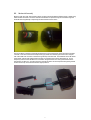
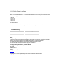
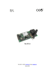
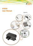
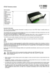
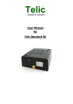
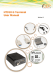
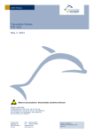
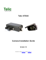
Telic STD35
Camera Installation Guide
Version 1.0
Telic GmbH – Internet: www.telic.de; E-mail: [email protected]
1
Introduction ................................................................................................................................................... 3
Attention, please read this....................................................................................................................... 4
2
Installing the Camera .................................................................................................................................... 5
2.1
The Connector ........................................................................................................................................ 5
2.2
Mechanical Assembly ............................................................................................................................. 6
2.3
Enabling Camera in Software ................................................................................................................. 7
3
Document history .......................................................................................................................................... 7
1.1
2
1 Introduction
Thank you very much for purchasing our Telic STD35 telemetry device and optional Telic Camera!
We wish you success and joy in using your new STD35!
The STD35 offers the possibility to monitor an object or a room with the help of the optional Telic camera for the
STD35. You can retrieve an actual picture form the STD35 using any computer worldwide that is connected to
the internet (e.g. to check the weather conditions at your holiday home).
In addition a picture can be sent as an attachment to the preconfigured e-mail address in the case of an alarm.
This allows you to take further action if necessary (e.g. call the police if you see a burglar on the photo)
To be able to use this functionality you only have to connect the Telic camera to the camera plug on the STD35
(see picture 1).
After the software of the STD35 has recognized the camera the pictures can be viewed our sent via e-mail in the
following ways:
- Access of the web-browser through the internet and click on “Photo”-Page
- E-mail with JPEG attachment in alarm situation
- E-mail with JPEG attachment after incoming call
- E-mail with JPEG attachment after SMS request
In case the light intensity is not enough at the survey area the infrared light of the camera will be activated
automatically. Please note that due to the infrared light there will be a loss of colours in the picture.
The Telic camera has an adjustable sun shade (metal plate over the camera). Please take into consideration
when adjusting the sun shade that the shadows are often changing during the day.
TIP:
To make sure that all desired objects will be in the picture, that the sun shade is in a good position
and/or that the illumination of the room will lead to satisfactory picture we recommend to take “test
pictures” after the installation. Only then you can rely on the full functionality of the Telic camera.
Concerning the user manual:
This document is meant to help you use the various functions of the device in the most optimal way possible.
Therefore we ask you to please read this manual carefully and completely.
The information in this document has been gathered after thorough investigation but should not to be taken as
assurance of end product properties.
The written approval of Telic GmbH is mandatory before you can pass on or reproduce this documentation for
this product or the software or use the content.
Telic reserves the right to change the data mentioned here without prior notice and does not take any
responsibility for technical inaccuracies and/or omissions. This manual has been thoroughly checked; should
you nevertheless find an error or want to express criticism or make suggestions, please send an e-mail to
E-mail: [email protected]
Oberhaching, 16 Dec. 2010
© 2010 Telic GmbH, Oberhaching, Germany
3
1.1
Attention, please read this
This user manual contains important information regarding installation of the Telic Camera module in an STD35.
Read it carefully before attempting to start working with the STD35 if the Camera module will be used.
The warranty will be null and void should damage occur due to non-compliance with these instructions for use.
We cannot accept any responsibility for consequential loss.
We cannot be held responsible for material loss or personal injury that is due to incompetent use or noncompliance with the safety instructions. The warranty will be null and void in such circumstances.
The STD35 and optional camera contain highly integrated components which can be damaged by electrostatic
discharge.
Therefore only touch the STD35 case and avoid touching the pins of components on the board.
Safety Instructions
When using products which are exposed to electric voltage the valid VDE-regulations have to be
observed. Especially VDE 0100, VDE 0550/0551, VDE 0700, VDE 0711 and VDE 0860 are
applicable.
• All wiring work has to be done in a voltage free state only
• All cables and wires which are energized and connected to the device, the module, or components have to be
checked regularly for any damage to the isolation shielding or fractures in the cables. If the supply cables are
visibly damaged the device has to be taken out of operation immediately until the faulty cable has been
exchanged
• Before putting a device into operation, it has to be clarified, whether this device or module is appropriate for
the field of application. In case of doubt ask a specialists or the manufacturer of the device.
• Please note that we are not responsible for any errors in usage or connection. Therefore we cannot accept
any responsibility for consequential loss.
• Before opening the device always disconnect the mains adapter or make sure that the device is disconnected
from the power supply.
• Components, modules or devices have to be built into a housing before they are put into operation. During
installation they should not be connected to any power supply.
• You should only use tools on components, modules, or devices if they are disconnected from the power
supply, and residual electric charge (which may still be stored in some components inside the device) has
been discharged.
• When using components or modules it is necessary to strictly observe the specification given in the
corresponding description of these components.
• If a description for a private end-customer does not clearly state which electric data is valid for a component or
a module, how to wire the device, which external components, or additional devices can be connected or
which parameters these components are allowed to have, a specialist must be contacted.
• Devices which operate with greater than 35 Volts have to be connected by a specialist.
• Before putting the device into operation it should be checked that there is no current leakage on the housing.
• In case measurements with the opened housing are necessary, an isolating-transformer has to be used for
safety reasons. Alternatively the voltage can be supplied by an appropriate power supply which complies with
the safety regulations. All wiring work has to be done in a voltage free state only.
4
2 Installing the Camera
2.1 The Connector
Inside the STD35 is the camera connector. The connector is designed to pair with the connector of the Telic
Camera module. There is a small tab on the Camera Module connector that ensures that the connector can
only be inserted in the correct orientation.
5
2.2
Mechanical Assembly
Because of the size of the Telic Camera modules connector and the fact that the STD35 housing is sealed using
water resistant Grommets some minor mechanical modification is required to bring the connector through the
Grommet without significantly compromising the water resistance of the device.
The way to get the connector to fit through the Grommet is to first cut the top bar off the Telic Camera module’s
connector. Then remove the Grommet Cap and the grey rubber seal inside the grommet and cut it along the
side of the rubber seal. Push the connector through the cap of the Grommet. Then while the seal is still outside
the grommet, open the seal slightly where it has been cut and thread the connector through the cut. Do not
worry that you have cut the seal when it is re inserted in the grommet the force of the grommet will close the
area where it has been cut. Once the connector is through the seal it can then be pushed through the grommet
and the seal and cap can be returned to there original positions.
6
2.3
Enabling Camera in Software
You can deactivate the camera functionality when the camera is connected to the STD35 with the command
“CAM:0.” and activate it with “CAM:x.”. The camera offers different resolutions and you can select the desired
camera resolution (x):
1 = 80 x 60
3 = 160 x 120
5 = 320 x 240
7 = 640 x 480
The default value is 7.
For more details on correct software operation of the Camera module please see the STD35 user manual.
3 Document history
Revision
Rev. 1.0
16th
Datum
Dec 2010
Changes
Original file
Imprint
These operating instructions are published by Telic GmbH
No reproduction (including translation) is permitted in whole or part e.g. photocopy, microfilming or storage in
electronic data processing equipment, without the express written consent of the publisher.
The operating instructions reflect the current technical specifications at time of print.
We reserve the right to change the technical or physical specifications.
© Copyright 2010 by Telic GmbH – printed in Germany
Telic GmbH
Raiffeisenallee 12b
D-82041 Oberhaching
Germany
www.telic.de
Telic reserves the right to change, correct and/or improve the content any time and without prior notice without
being obliged to do so. No responsibility is taken for the correctness of the information.
7