1
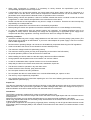
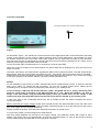
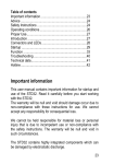
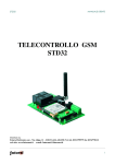
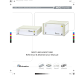
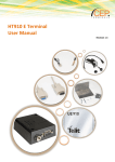
STD35 Telemetry module
User Manual
Table of contents
Subjects
Important Information
Advice
Safety instructions
Operation conditions
Proper use
Introduction
Connectors and LEDs
Startup
General aspects
Configuration call
Usage
Tracking via GPS
Modem functionality
Trouble shooting
Technical data
Page
1
1
1
2
2
2
3
3
4
4
4
7
8
8
9
Important Information
This user manual contains important information for startup and use of the STD35. Read it carefully before you
start working with the STD35.
The warranty will be null and void should damage occur due to non-compliance with these instructions for use. We
cannot accept any responsibility for consequential loss.
We cannot be held responsible for material loss or personal injury that is due to incompetent use or noncompliance with the safety instructions. The warranty will be null and void in such circumstances.
The STD35 contains highly integrated components which can be damaged by electrostatic discharge.
Therefore only touch the STD35 on the edges and avoid to touch the pins of components
on the board.
Advice
The one who makes the module operational by adding further components or putting it into a housing, is seen as
manufacturer according to DIN VDE 0869 and obliged to hand out all necessary documents with the device and to
indicate his name and address. Devices which are made out of modules have to be considered as an industrial
product from the safety perspective.
During use of the STD35 Short Messages (SMS) can be generated automatically. Costs may occur for you by this
SMS traffic.
Safety Instructions
When using products which are exposed to electric voltage the valid VDE-regulations have
to be observed. Especially VDE 0100, VDE 0550/0551, VDE 0700, VDE 0711 and VDE
0860 are applicable.
• Before opening of a device always pull the mains adapter or make sure that the device is disconnected from the
power supply.
• Components, modules or devices have to be build into a housing before they are put into operation. During
installation they should not be connected to any power supply .
• You should only use tools on components, modules or devices if they are disconnected from the power supply
and the electric charge, which may still be stored in some components, inside the device has been discharged.
• All cables and wires which are energized and connected to the device, the module or components have to be
checked regularly for any damage of the isolation shield or fractures of the cables. If the supply cables are
visibly damaged the device has to be taken out of operation immediately until the faulty cable has been
exchanged.
1
• When using components or modules it is necessary to strictly observe the specification given in the
corresponding description of these components.
• If a description for a private end-customer not clearly states which electric data is valid for a component or a
module, how to wire the device, which external components or additional devices can be connected or which
parameters these components are allowed to have, a specialist must be contacted.
• Before putting a device into operation, it has to be clarified, whether this device or module is meant for the field
of application. In case of doubt ask specialists or the manufacturer of the device.
• Please note that we are not responsible for any errors in usage or connection. Therefore we cannot accept any
responsibility for consequential loss.
• Devices which operate with >35 Volt have to be connected by a specialist.
• Before putting the device into operation it should be checked that there is no current leakage on the housing.
• In case that measurements with the opened housing are necessary, an isolating-transformer has to be
integrated for saftey reasons. Alternatively the voltage can be supplied by an appropriate power supply which
complies with the safety regulations. All wiring work has to be done in a voltage free state only.
Operating conditions
• Operate the STD35 only with a supply voltage between 5-32V and have in mind the polarity! (see picture1) The
power supply has to deliver at least 500mA. If you use a mains adapter for power supply it has to be conform
with the VDE regulations.
• Devices with an operating voltage >35 Volt have to be installed by a specialist observing the VDE regulations.
• Loads connected to the device are not allowed to exceed 1000W per relay.
• The maximum voltage is 250V AC (alternating current)
• The maximum switching power per relay is 6A (depending on the width of the PCB tracks)
• No special operation position of the device has to be observed.
• When installing the device make sure that the supply cable has a sufficient diameter
• During operation the temperature has to be between -20° and 55° Celsius.
• In case of condensation allow a period of about 2 hours for acclimatisation.
• Keep away the device from flower vases, bath tubs, washbasins, liquids etc.
• The device is meant for operation in dry and clean rooms.
• Protect the device from humidity, spray water and heat.
• Do not expose the device to heavy vibrations.
• Do not operate the device in areas where are or could be inflammable gas, vapours or dust.
• The unit may only be repaired by a specialist.
• Only original parts have to be used when repairing the unit. The use of differing spare parts can cause serious
material loss or personal injury.
Proper Use
The device is designed for the remote switching of devices via the GSM network as well as the remote retrieval of
status information of the inputs and the generation of SMS messages after status has changed at the inputs. A
different utilisation of the device other than the one described above is not allowed.
Introduction
The STD35 is a telemetry module which is easy to install and simple to use.
With the STD35 you can control five relays and monitor the status of five digital inputs with one or several common
mobile phones.
Apart from the STD35 you only need a valid SIM Card of any network provider (GSM 900 / 1800 MHz).
While using prepaid SIM-cards one shall always keep himself aware of the amount left on the card, so that in case
of alarms a SMS could be sent.
Typical fields of application are the opening of (garage) doors, switching on and off light and alarm devices as well
as generating alarm messages (SMS) or the retrieval of information from door sensors, movement sensors or level
sensors etc.
2
Connectors and LEDs
Connection Scheme of the 12V DC Voltage Supply
Figure 1
As described in figure 1, the STD35 has 6 screw terminals for the digital inputs and 6 screw terminals for the Relay
outputs. Screw terminal 1 is the common negative reference point for all 5 digital Inputs. The terminals 2 to 5 are
the positive reference points for the after coming opto couplers. On the output side are further 6 screw terminals,
from which the terminal 12 represents the common reference point and switching potential for all 5 relays. On the
PWR the power supply of the STD35 will be connected.
On the connection ANT the GSM antenna is to screwed in (connector type FME).
When the module is booked into the GSM network, the green GSM LED is blinking at the front side about once
within 2 seconds.
The LEDs „Input-Event“ and „Output-Event“ signalize the Status of the inputs and outputs. The LED „Output-Event“
blinks shortly, when one of the 5 relays is activated, the LED „Input-Event“, when one of the 5 inputs is controlled.
Please take into account the maximum switching current of the relays and the maximum input current and voltage
of the Opto couplers! In the chapter „Startup“ you will find further information for it!
Startup:
For the installation of the STD35 you need a released SIM card of a GSM network provider, on which the PIN has
been put to „0000“. To change the PIN accordingly, you can use a regular mobile phone. Please get the
proceeding for Pin change out of the corresponding user manual of your mobile phone.
In case of using a SIM card with another PIN than „0000“, the STD35 will use a „wrong“ PIN during each
power-on, which leads to blocking of the SIM card after the 3rd trial . When this happens, you have to
assign a new PIN number using the Super-PIN (PUK). Please get related advice for the change of PIN
number and reset of blocked PIN number with the PUK out of the user manual of your mobile phone.
In case your want to use a SIM-Karte without PIN, this is possible as well; the STD35 recognizes this and is
running accordingly.
Before connecting the supply voltage, please enter the SIM card into the SIM-card holder on the rear side of the
STD35. Displace the moving part of the SIM card holder a little bit and open it. Enter the SIM card into the moving
part, close it again and fix it by slight displacing.
Please consider the position of the SIM card, especially the position of the flat corner.
If not yet done, please connect and tighten the GSM antenna.
After that, please establish the connection to the supply voltage. The GSM-LED, shortly after, begins to shine
steadily. The STD35 will try now automatically, to book into the GSM network. As soon as the STD35 is booked
into the GSM network, the GSM-LED once for around all 2 seconds.
3
General aspects:
Your STD35 can basically be configured in 2 ways:
1. Configuration-Call („easy-setup“)
In factory status the STD35 can be configured by a call within the first 3 minutes after connecting to the supply
voltage. In this case is „logging“ the phone number, from which this call has been made (supposing, that this
number is transmitted), and will report future event to this phone number.
You can switch by a call from this phone, from now on known to the STD35, also one of the relays.
The total STD35 can so be configured by call, in which it is remembering the phone number, for simple
applications. You don’t need a PC for it and don’t need to send SMS neither.
2. Configuration via SMS („professional setup“)
For more complexe tasks, e.g. the switching of the 5 outputs, the configuration of several persons being authorized
to switch or get event messages, the modification of the standard texts and a number of further parameters the
STD35 via SMS configured and controlled in a very flexible way.
Even the Reset into the factory status, e.g. to proceed for y new configuration call, is possible.
The configuration via SMS is described under „SMS commands“.
Configuration-Call
Please wait, until the GSM-LED has started to blink.
Then please call with the mobile phone, which is assigned to control the STD35, the phone number of the SIM card
being inside of the STD35. The call will be accepted by the STD35 and will be terminated a couple of seconds
later. As a control sign five signal tones will be sent via DTMF sequences! They can be heard during this call on
your mobile phone.
Due to this call the STD35 will be adjusted to the corresponding mobile phone, it will „log“ Your phone number, that
has been transmitted.
Therefore please take care, that your mobile phone will transmit the phone number, means the GSM
function „incognito“ or „private call“ has to be switched off.
This is a configuration, that you can settle on your mobile phone, in which you put in the SIM card. (For testing this
feature you can call another mobile phone, there your phone number or name have to be displayed)
In case the STD35 e.g. due to being separated from the supply voltage, the STD35 will send, after the reapparition
of the supply voltage, automatically an SMS with the content „START-UP ALARM“ being sent to the configured
phone number.
Please consider: When the STD35 is not confirgured in factory status (neither by configurations call nor by
SMS), it will show this by alternative blinking of the LEDs „Input-Event“ and „Output-Event“. It is switching
off after 3 minutes autonomously, when not being configured within this time slot. A renewed connecting
to the power supply will switch on the STD35 anew, and it is expecting again a configuration.
Usage
After being configured, the following functions of the STD35 will be at your disposition:
Switching per call
Please call, after made configuration, the phone number of the SIM card being inside of the STD35. Please take
care, that your mobile phone is transmitting the phone number. (see as well „configuration call“). The relay 1
will then, depending on the configuration, switch for a certain time (factory status: 1 sec). The relays-status-LED
„Output-Event“ is on during this period.
Launch an Alarm SMS
Put for 1 second (Factory configuration) a voltage of 12V at one of the inputs, consider the polarization! Then an
alarm SMS will be sent to your mobile phone. The LED „input event“ is shortly flashing-up, when you put the
voltage to the STD35.
Sending SMS commands
Your STD35 can launch switching processes as well as be configured via an SMS, that you send to it.
The Format of the Configuration SMS:
To protect your STD35 against not authorized access, each of the configuration SMS to the STD35 has to begin
with a 4 digit password. The factory default provides the last 4 digits of the IMEI number for it! Your IMEI number is
visible on the GSM module:
4
The last 4 digits of the IMEI are therefore the password for your device and should be kept secretly from your side.
The IMEI number cannot be changed! You can also change the password for security relevant cases, but please
bare in mind that each command – also the reset to the factory status- will presumes the knowledge of this
password.
Control Commands via SMS:
Control commands via SMS will only be executed, if the phone number of the sender has been communicated to
the STD35 before. Control commands don’t need a password.
All command (with exception of R: and ST?) have to be terminated with a dot!
All commands can be sent in one SMS, separated one from the other by the terminating dot.
The indications of the seconds can have 1-5 digits. Valid indications are e.g.: 1 or 90 or 99999, that means there
won’t be put leading Zeros before the digits (e.g. “O1:90”. This is euiqvalent of 90 seconds).
Please pay attention to the difference between the number 0 and the letter O! (“O1ON.” Contains two times
the letter O, whereas “O1:0” contains once the letter O and once the number 0).
Basic functions
• After having been called from the assigned („stored“, pls. See configuration call) mobile phone, the relay 1
switches for a second.
• When the digital input1 will be activated for a second, the STD35 sends a SMS with the content „EVENT
ALARM 1“ to the assigned mobile phone.
• When the digital input2 will be activated for a second, the STD35 sends a SMS with the content „EVENT
ALARM 2“ to the assigned mobile phone.
• The same is certainly valid for the inputs 3 to 5.
Switching via SMS
• After having received a SMS with the content „O1ON.“ (=Output 1 ON) from the assigned mobile phone, the
relay 1 will switch for a second. In case of a SMS “O2ON.” The relay 2 will switch for a second.
• The same is certainly valid as well for the outputs “relay 3 to relay 5”.
• In the case that the switching time has been put to 0 (number 0), the relays switch permanently to the other
status.
Configuration SMS
• The configuration SMS is valid, only if beginning with the 4 digit password. Teh CLIP of each of the
configuration SMS will, if the password is correct, be logged automatically as a new administrator. Therefore it
has to be considered, that the configuration only is executed from the mobile phone of the administrator.
• With a SMS having the content „O1:xxxxx.“ (character O= (xxxxx = seconds) the switching times of the relays
can be configured. The STD35 will keep these configurations even after the cut-off from the supply voltage.
• In case that the switching time for a relay has been put to 0, the STD35 will, at each new call, switch the related
relay permanently. Has the relay been active before, it will go to inactive and vice versa.
In this case also a SMS containing “O1ON.” from the assigned mobile phone will switch the relay 1 on
permanently. A SMS with the content “O1OFF.” will then switch the relay 1 again off permanently. Accordingly
the relays 2 to 5 will react on SMS messages which contain “OxON.” And “OxOFF.” (x=2...5).
•
By a SMS with the content e.g. “I1:xxx.” (xxx=seconds) the times can be programmed for the five inputs, during
which these inputs have to be active, before the STD35 will send out an alarm SMS.
The inputs 2 to 5 show the identical behavior.
•
By a SMS with the content e.g. “V1:x.” Or “V2:x.” (x = 1 oder 0) the polarity of the inputs can be inverted. In
case of x=1 there will be sent a alarm SMS, if the input was deactivated longer then the configured time. For
the inputs 3 to 5 equivalent proceeding is valid (e.g. V4:x.).
5
• Using the SMS „S:x.“ (x = 1 or 0) the Start SMS (START-UP ALARM) can be switched-on or –off.
• The SMS „R:“ will set back the device into the factory status.
• Via the SMS „ST?“ you can ask for a response SMS from the STD35 with the actual status of the inputs and
outputs. The same functionality can be achieved pushing the button on the upper side of the STD35, being
under the LED. Please consider, that each of the pushings will lead to the sending of a SMS and so will create
costs for you.
• With the SMS, e.g. for the outputs 1 and 2, “A1:xxx.” Or “A2:xxx.” (x = seconds) you can adjust the delay, after
which, after a switching, the status will be sent in the response SMS. This ist e.g. very helpful, if you launch a
switching and you measure the result of the switching on an input of the STD35. Using this, the changed status
after the switching will be signalized. For the outputs 3 to 5 the same behavior will happen.
• The command „PN:<4digit password>.“. will change the password. The password can consist in 4 freely chosen
numbers or character combinations, special signs are not allowed. Characters within the password have to be
written in capital letters. In factory status the password is always the last 4 digits of the IMEI, see also chapter “
SMS commands”.
• You can define up to four further alarm numbers (master numbers C2:-C5:), to which also Start and Event SMS
will be sent. These numbers can also switch the relay 1 by call and can execute other control commands via
SMS. Configuration SMS though can only be sent successfully from the administrator’s side.
If the alarm numbers are entered in international format, they have to start with a „+“• You can give authorization to up to one hundred of further phone numbers to switch the relay 1 by call. To do
so, you have to build up the “extended Clip” list respectively you have to enter phone numbers into this Clip list.
You can also, using “CD:”, erase again phone numbers within this list.
• The texts for Event respectively Start-up messages can be modified using the commands
E1:<text1>.,E2:text2>. Up to E5:<text5>. And PT:<startup-text>. Within the texts no SMS command for
configuration is allowed and the final dot is terminating the text. Each text message can have up to max. 64
characters. Each text input has to be done in a separate SMS.
Table of SMS Commands
Factory settings
Status of I/Os
Start SMS on/off
Relay 1 on
Relay 1 off
Relay 2 on
Relay 2 off
Relay 3 on
Relay 3 off
Relay 4 on
Relay 4 off
Relay 5 on
Relay 5 off
Switching time Relay 1
R:
ST?
S:1. / S:0.
O1ON.
O1OFF.
O2ON.
O2OFF.
O3ON.
O3OFF.
O4ON.
O4OFF.
O5ON.
O5OFF.
O1:xxxxx. (Seconds)
Switching time Relay 2
Switching time Relay 3
Switching time Relay 4
Switching time Relay 5
Delay before reply Relay 1
Delay before reply Relay 2
Delay before reply Relay 3
Delay before reply Relay 4
Delay before reply Relay 5
Time of activation Input 1
Time of activation Input 2
Time of activation Input 3
Time of activation Input 4
Time of activation Input 5
Invert Input 1
Invert Input 2
Invert Input 3
Invert Input 4
Invert Input 5
2. Alarm number
O2:xxxxx. (Seconds)
O3:xxxxx. Seconds)
O4:xxxxx. (Seconds)
O5:xxxxx. (Seconds)
A1:xxx. (Seconds)
A2:xxx. (Seconds)
A3:xxx. (Seconds)
A4:xxx. (Seconds)
A5:xxx. (Seconds)
I1:xxx. (Seconds)
I2:xxx. Seconds)
I3:xxx. (Seconds)
I4:xxx. (Seconds)
I5:xxx. (Seconds)
V1:x. (x= 1/0 )
V2:x. (x= 1/0 )
V3:x. (x= 1/0 )
V4:x. (x= 1/0 )
V5:x. (x= 1/0 )
C2:<number>.
6
3. Alarm number
4. Alarm number
5. Alarm number
New Password
Event Text 1
Event Text 2
Event Text 3
Event Text 4
Event Text 5
Start Up Text
Add Clip to the extended Cliplist
Remove Clip from the extended Cliplist
C3:<number>.
C4:<number>.
C5:<number>.
PN:<4digit password>.
E1:<text>.
E2:<text>.
E3:<text>.
E4:<text>.
E5:<text>.
PT:<text>.
CL:<nummer>.
CD:<nummer>.
Examples for SMS Commands
Configuration using control command: Start message Off, Relay 1 On, Relais 2 Off, Time of activation of input 1: 5
sec.:
2759 S:0.O1ON.O2OFF.I1:5.
The sender of this SMS is from now on Administrator
Configuration: Switching time of Relay 1 = 90 Sekunden:
Configuration: Reset to factory settings:
Configuration of a 2nd Alarm number:
Erasing of an Alarm number
2759 O1:90.
2759 R:
2759 C2:+491721234567.
2759 C2:.
Configuration of a new password:
2759 PN:AB12.
New Number in extenden Clip list:
2759 CL:+491721234567.
Remove Number from extended Clip list:
2759 CD:+491721234567.
Control commands
O1ON O2OFF O3ON
Tracking via GPS
By plugging of an appropriate GPS Mouse on the serial connector (DSUB 9) of the front side of the STD35, you
can transmit the GPS data directly to your mobile phone. This function can be launched from the Admin
respectively the 4 additional Masters durchgeführt werden. The users, who are in the extended Cliplist, can Not use
this function! To ask for actual position of your STD35, please use the following SMS commands:
GPS?
After reception of this SMS the STD35 sends a SMS with the following text to your mobile phone:
$GPGGA,<1>,<2>,<3>,<4>,<5>,<6>,<7>,<8>,<9>,M,
$GPGGA,083537.00,4802.00364,N,01135.21171,E,1,4,7.95,579.8,M,47.5,M,,*61
1 UTC time
2 Latitude
3 Hemisphere
4 Longitude
5 Hemisphere
6 Position fix
7 Number of Satellites
8 horizontal Precision
9 Height over sea level
Unit of height
hh=08;mm=35;ss=37.00 corresp. 09:35:37 MEZ
Latitude: 48 Degrees; 02.00364 Minutes
N nordic Latitude
Longitude: 11 Degrees; 35,21171 Minutes
E eastern Longitude
0 No fix; 1 GPS SPS mode; 2 DGPS mode; 3
GPS PPS mode
4 Satellites used for Position
Precision of the Position: 7,95 Meters
579.8 Meters
M for meters
7
10 Age of the GPS Data
here No DGPS used
A GPS tracking can also be asked by call. This function however is only possible for the Admin and the 4 futher
Masters. For being able to use this function, the default status (call switches relay 1) has to be changed by the
Admin. This is done from the Admin’s side sending a SMS with the following content:
2759 G1:x.
x=0
Calls from Admin and the Masters switch Relay 1 (factory setting)
x=1
Calls from Admin or the 4 Masters launch a tracking request; for which the reply will be sent back
exclusively to the number having called.
For the possible 90 Users on the extended Cliplist it is still possible to switch the relay 1 by call, even though the
command <2759 G1:1> has been sent from the Admin’s side.
Please consider, that for the connection of GPS mouse probably a Zero-Modem adaptor has to be put
between the RS232 connector of the STD35 and the GPS mouse.
Modification of the Baudrate for different GPS-Mouses:
Since GPS-Mouses from different manufacturers work with different baudrates, the baudrate of the STD35 can be
put to 9600 Baud and 4800 Baud. Therefore the following configuration command has to be sent to the STD35:
2759 BR:x.
x=0
x=1
Baudrate 9600 (Factory setting)
Baudrate 4800 Baud
Modem Functionality of the STD35
For using the Modem functionality of the STD35, the serial interface has to be modified using a terminal program.
The STD35 is put to 9600 Baud 8N1 as the factory setting. After connecting the RS232 with a terminal program on
the PC, just the simple command <at> has to be sent. Then the user has the full GSM modem functionality at his
disposition.
During the Modem functionality the GPS funktionality is deactivated. To reactivate it, a command via the terminal
program has to be sent to the STD35. This command is as follows:
at*e2apc=2,3 (pushing the Return button)
Troubleshooting
Problem
GSM-LED stays dark
GSM-LED is blinking from the
beginning twice cyclicly
GSM-LED is blinking from the
beginning thrice cyclicly
GSM-LED constantly on
GSM-LED gets dark after
about 3 minutes
STD35 does Not react on
configuration call(not
Possible reason
No supply voltage
No SIM card / No contact to the
SIM card
PIN is Not „0000“
Solution
Please connect power supply
Surface of the SIM card to clean
SIM card PIN to be set to „0000“
No GSM Network available/ No
Antenna connectec
Not configured
Antenna to connect /please change
position of antenna
Configuration Call to be done
Device is already configured
Please Reset to Factory settings.
8
accepting the call)
STD35 does Not react to
Configuration SMS
STD35 doesn’t react on SMS
or Calls, even though being
booked to GSM Network
Both red LEDs blink
consecutively
Wrong IMEI Number in the SMS /
SMS not yet delivered
The Mobile phone doesn’t send
the phone number („Incognito
Mode“)
The configuration call hasn’t been
done yet.
IMEI Number to be checked. / SMS
delivery can take some time
Please configure Mobile phone in
the way, that the phone number is
also transmitted.
Please do configuration call
Technical Data
• GSM: Dual Band EGSM 900/1800 MHz, compatible with ETSI GSM Phase 2+ Standard
• Output power:
Class 4 (2W @ 900 MHz)
Class 1 (1W @ 1800 MHz)
• Temperature range: -20°C - +75°C
• Weight: approx. 160g
• Dimensions: 130x85x30 mm (LxBxH)
• Supply voltage: 5-32V DC
• Idle current: 32 mA, peak current up to 500 mA
• Max. Switching current: 5 A
Max. Switching voltage: 30V AC
• Input voltage (digital inputs)
logic 1:
5 - 20V
logic 0:
< 1,5V
I case of technical problems and questions concerning the STD35 our Hotline is available for you:
Mo. – Fr.: 9:00 a.m. – 5:00 p.m.
Techn. Hotline:
For other questions about the STD35 please dial:Sales
+49 (0)89 / 4902 686 11
+49 (0)89 / 4902 686 29
Issue: April 2005, Subject to change without notice !
Telic GmbH, Raiffeisenallee 12b D-82041 Oberhaching – www.telic.de – [email protected]
9