1
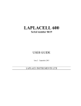
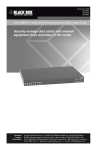
NGIMU User Manual Version 0.0 Preliminary Release Copyright © 2015 x-io Technologies Ltd. www.x-io.co.uk NGIMU User Manual Version 0.0 10 May 2015 Document updates This document is continuously being updated to incorporate additional information requested by users and new features made available in software and firmware updates. Please check the x-io Technologies website for the latest version of this document and device firmware. Document version history Date Document version Description 10 May 2015 0.0 Initial release www.x-io.co.uk 2 / 10 © 2015 NGIMU User Manual Version 0.0 10 May 2015 Table of Contents 1. Overview...............................................................................................................................................4 1.1. On-board sensors & data acquisition............................................................................................4 1.2. On-board data processing .............................................................................................................4 1.3. Communication interfaces ............................................................................................................4 1.4. Power management ......................................................................................................................5 1.5. Software features..........................................................................................................................5 2. Hardware ..............................................................................................................................................6 2.1. Power button ................................................................................................................................7 2.2. LEDs ...............................................................................................................................................7 2.3. Auxiliary serial pinout ...................................................................................................................7 2.4. Serial pinout ..................................................................................................................................8 2.5. Analogue input pinout ..................................................................................................................8 2.6. Connector part numbers ...............................................................................................................8 3. Plastic housing ......................................................................................................................................9 www.x-io.co.uk 3 / 10 © 2015 NGIMU User Manual Version 0.0 10 May 2015 1. Overview The Next Generation IMU (NGIMU) is a compact IMU and data acquisition platform that combines on-board sensors and data processing algorithms with a broad range of communication interfaces to create a versatile platform well suited to both real-time and data-logging applications. The device communicates using OSC and so is immediately compatible with many software applications and straight forward to integrate with custom applications with libraries available for most programming languages. 1.1. On-board sensors & data acquisition Triple-axis gyroscope (±2000°/s, 400 Hz sample rate) Triple-axis accelerometer (±16g, 400 Hz sample rate) Triple-axis magnetometer (±1300 µT) Barometric pressure (300-1100 hPa) Humidity Temperature1 Battery voltage, current, percentage, and time remaining Analogue inputs (8 channels, 0-3.3 V, 10-bit, 1 kHz sample rate) Auxiliary serial (RS-232 compatible) for GPS or custom electronics/sensors Real-time clock and calendar2 1.2. On-board data processing All sensors are calibrated2 AHRS fusion algorithm provides a measurement of orientation relative to the Earth as a quaternion, rotation matrix, or Euler angles AHRS fusion algorithm provides a measurement of linear acceleration Altimeter fusion algorithm provides a measurement of altitude2 All measurements are timestamped Synchronisation of timestamps for all devices on a Wi-Fi network2,3 1.3. Communication interfaces USB Serial (RS-232 compatible) Wi-Fi (802.11n, 5 GHz, built-in or external antennae, AP or client mode) SD card (accessible as an external drive via USB)2 1 On-board thermometers are used for calibration and are not intended to provide an accurate measurement of ambient temperature. 2 This feature is under development and will be available soon. requirement. 3 Please contact us if this is an urgent Synchronisation requires additional hardware (Wi-Fi router and synchronisation master). www.x-io.co.uk 4 / 10 © 2015 NGIMU User Manual Version 0.0 10 May 2015 1.4. Power management Power from USB, external supply or battery Battery charging via USB or external supply Sleep timer Motion trigger wake up Wake up timer2 3.3 V supply for user electronics (500 mA) 1.5. Software features www.x-io.co.uk Open-source GUI and API (C#) for Windows Configure device settings Plot real-time data Log real-time data to file (CSV file format for use with Excel, MATLAB, etc.) Maintenance and calibration tools 5 / 10 © 2015 NGIMU User Manual Version 0.0 10 May 2015 2. Hardware Serial interface Auxiliary serial interface Barometric pressure and humidity sensor Power button Gyroscope, accelerometer and magnetometer The correct axis directions are: X Y Z USB Battery connector Analogue inputs LEDs Figure 1: Top view of board The correct axis directions are: External 5 V input solder pads X Z Y External antenna UF.L connector SD card socket Internal antenna Figure 2: Bottom view of board www.x-io.co.uk 6 / 10 © 2015 NGIMU User Manual Version 0.0 10 May 2015 2.1. Power button The power button is primarily used to turn the device on and off (sleep mode). Pressing the button while the device is off will turn it on. Pressing and holding the button for 3 seconds while it is on will turn it off. The button can also be used as a data source by the user. The device will send a timestamped ‘button’ message (/button) each time the button is pressed. This may provide a convenient user input for real-time applications or a useful means of marking events when logging data. The user must be careful not to hold the button for too long else device will be turned off. 2.2. LEDs The board features 5 LED indicators. Each LED is a different colour and has a dedicated role. Table 1 list the role and associated behaviour of each LED. Colour Indicates Behaviour White Wi-Fi status Off = Wi-Fi disabled Flashing = Wi-Fi enabled but not connected Solid = Wi-Fi enabled and connected Blue - - Green Power Indicates that the device is switched on. Will also blink each time the button is pressed of a message is received. Yellow - - Red Battery charging Off = Charger not connected Solid = Charger connected and charging in progress Flashing = Charger connected and charging complete Table 1: LED behaviour Sending an ‘identify’ message (/identify) to the device will cause all the LEDs to rapidly flash for 5 seconds. This may be of use when trying to identify a specific device within a group of multiple devices. 2.3. Auxiliary serial pinout Table 2 lists the auxiliary serial connector pinout. Pin 1 is physically marked on the connector by a small arrow. www.x-io.co.uk Pin Direction Name 1 N/A Ground 2 Output CTS 3 Input RX 4 Output TX 5 Input 3.3 V output 7 / 10 © 2015 NGIMU User Manual Version 0.0 10 May 2015 6 Input RTS Table 2: Auxiliary serial connector pinout 2.4. Serial pinout Table 3 lists the serial connector pinout. Pin 1 is physically marked on the connector by a small arrow. Pin Direction Name 1 N/A Ground 2 Output CTS 3 Input RX 4 Output TX 5 Input 5 V input 6 Input RTS Table 3: Serial connector pinout 2.5. Analogue input pinout Table 4 lists the analogue input connector pinout. Pin 1 is physically marked on the connector by a small arrow. Pin Direction Name 1 N/A Ground 2 Output 3.3 V output 3 Input Analogue channel 1 4 Input Analogue channel 2 5 Input Analogue channel 3 6 Input Analogue channel 4 7 Input Analogue channel 5 8 Input Analogue channel 6 9 Input Analogue channel 7 10 Input Analogue channel 8 Table 4: Analogue input connector pinout 2.6. Connector part numbers All board connectors are 1.25 mm pitch Molex PicoBlade™ Headers. Table 5 lists each part number used on the board and the recommended part numbers of the corresponding mating connectors. Each mating connector is created from a plastic housing part and two or more crimped wires. www.x-io.co.uk 8 / 10 © 2015 NGIMU User Manual Version 0.0 10 May 2015 Board connector Part number Mating part number Battery Molex PicoBlade™ Header, Surface Mount, Right-Angle, 2-way, P/N: 53261-0271 Molex PicoBlade™ Housing, Female, 2way, P/N: 51021-0200 Molex PicoBlade™ Header, Surface Mount, Right-Angle, 6-way, P/N: 53261-0671 Molex PicoBlade™ Housing, Female, 6way, P/N: 51021-0600 Molex PicoBlade™ Header, Surface Mount, Right-Angle, 10-way, P/N: 53261-1071 Molex PicoBlade™ Housing, Female, 10way, P/N: 51021-1000 Auxiliary serial / Serial Analogue inputs Molex Pre-Crimped Lead Single-Ended PicoBlade™ Female, 304mm, 28 AWG, P/N: 06-66-0015 (×2) Molex Pre-Crimped Lead Single-Ended PicoBlade™ Female, 304mm, 28 AWG, P/N: 06-66-0015 (×6) Molex Pre-Crimped Lead Single-Ended PicoBlade™ Female, 304mm, 28 AWG, P/N: 06-66-0015 (×10) Table 5: Board connector part numbers 3. Plastic housing The plastic housing is not currently available but is in the final stages of development. The plastic housing encloses the board with a 1000 mAh battery. Figure 3 shows a 3D printed prototype of the plastic housing. Figure 3: 3D printed prototype of the plastic housing www.x-io.co.uk 9 / 10 © 2015 NGIMU User Manual Version 0.0 10 May 2015 The plastic housing is made of a 2-part plastic shell held together by a silicon rubber band. The silicon rubber band has optional cut outs to provide access to the board connectors. If these cut outs are left in place then the plastic housing may offer a degree of protection from water and dust. Figure 4 shows the plastic housing unassembled. Figure 4: Unassembled 3D printed prototype of the plastic housing www.x-io.co.uk 10 / 10 © 2015