1
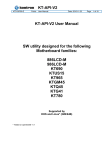
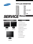
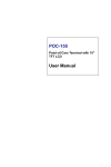
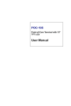
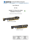
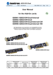
ADD2-LVDS KTD-00711-D Public User Manual Date: 2008-09-16 Page 1 of 13 User Manual for the 820950 ADD2-LVDS-Dual card 820953 ADD2-LVDS-Single card AGP Digital Display second generation card with Low Voltage Differential Signaling Transmitter Designed primarily for 986LCD-M family and KT965/Flex motherboards 820950 ADD2-LVDS-Dual 820953 ADD2-LVDS-Single Part no. PCB no. Ass. no. ADD2-LVDS-Dual 820950 30103260 68600002 ADD2-LVDS-Single 820953 30103260 68400000 ADD2-LVDS KTD-00711-D Public User Manual Date: 2008-09-16 Page 2 of 13 Document revision history. Revision Date By D C B A 0 th MLA MLA MLA MLA MLA Sept. 16 2008 Sept. 4th, 2007 Aug. 20th, 2007 Mar. 13th , 2007 Jan. 19th , 2007 Comment Page 7, “PWR connector” text improved. MB specific configuration added to Installation Guide. 820953 Picture added. Minor layout changes. Add ADD2-LVDS-Single Preliminary version. Copyright Notice: Copyright © 2007, KONTRON Technology A/S, ALL RIGHTS RESERVED. No part of this document may be reproduced or transmitted in any form or by any means, electronically or mechanically, for any purpose, without the express written permission of KONTRON Technology A/S. Trademark Acknowledgement: Brand and product names are trademarks or registered trademarks of their respective owners. Disclaimer: KONTRON Technology A/S reserves the right to make changes, without notice, to any product, including circuits and/or software described or contained in this manual in order to improve design and/or performance. Specifications listed in this manual are subject to change without notice. KONTRON Technology assumes no responsibility or liability for the use of the described product(s), conveys no license or title under any patent, copyright, or mask work rights to these products, and makes no representations or warranties that these products are free from patent, copyright, or mask work right infringement, unless otherwise specified. Applications that are described in this manual are for illustration purposes only. KONTRON Technology A/S makes no representation or warranty that such application will be suitable for the specified use without further testing or modification. ADD2-LVDS KTD-00711-D Public User Manual Date: 2008-09-16 Page 3 of 13 Life Support Policy KONTRON Technology’s PRODUCTS ARE NOT FOR USE AS CRITICAL COMPONENTS IN LIFE SUPPORT DEVICES OR SYSTEMS WITHOUT EXPRESS WRITTEN APPROVAL OF THE GENERAL MANAGER OF KONTRON Technology A/S. As used herein: 1. Life support devices or systems are devices or systems which, (a) are intended for surgical implant into body, or (b) support or sustain life and whose failure to perform, when properly used in accordance with instructions for use provided in the labeling, can be reasonably expected to result in significant injury to the user. 2. A critical component is any component of a life support device or system whose failure to perform can be reasonably expected to cause the failure of the life support device or system, or to affect its safety or effectiveness. KONTRON Technology Technical Support and Services If you have questions about installing or using your KONTRON Technology Product, check this User’s Manual first – you will find answers to most questions here. To obtain support, please contact your local Distributor or Field Application Engineer (FAE). Before Contacting Support: Please be prepared to provide as much information as possible: ADD-On Board 1. Type. 2. Part-number (Number starting with “68”). Configuration 1. Motherboard Type 2. BIOS Revision (Find the Version Info (BIOS ID) in the BIOS Setup Menu) 3. BIOS Settings different than Default Settings (Display related settings). 4. O/S Make and Version. 5. Graphic Driver Version numbers. 6. Attached LCD Panel(s) etc. ADD2-LVDS KTD-00711-D Public User Manual Date: 2008-09-16 Page 4 of 13 Table of contents: INTRODUCTION ................................................................................................................................................5 MECHANICAL DRAWING.................................................................................................................................5 FUNCTIONAL DIAGRAM ..................................................................................................................................6 CONNECTOR POSITION ..................................................................................................................................7 CONNECTOR DESCRIPTION...........................................................................................................................7 INSTALLATION GUIDE.....................................................................................................................................9 ELECTRICAL SPECIFICATION......................................................................................................................10 APPENDIX: HOW TO REMOVE LVDS CONNECTOR ..................................................................................11 APPENDIX: THE 820971 LDI EVALUATION KIT ..........................................................................................12 ADD2-LVDS KTD-00711-D Public User Manual Date: 2008-09-16 Page 5 of 13 Introduction • • • • • • • • • • • • • • • • • • Single or dual LVDS Transmitter each working as Single/Dual LVDS Transmitter up to 165Mpixels/s Panel fitting scalar-up scale to 1600x1200 Panel resolution up to 1920x1200 (@60Hz Frame Rate The ADD2-LVDS-Dual supported by KT965 Family The ADD2-LVDS-Single supported by KT965 and 986LCD-M Families LVDS low jitter PLL accepts spread spectrum input LVDS 18-bit and 24-bit output 2D dither engine Panel protection and power sequencing High-speed SDVO1 serial (1G~2Gbps) AC-coupled differential RGB inputs Low voltage interface support to graphics device Programmable power management Fully programmable through serial port Configuration through opcodes1 Complete Windows and DOS driver support 3.3/5V LCDVCC selection Backlight Signal inversion selection The ADD2-LVDS cards are based on the Chrontel CH7308A LVDS transmitter. The ADD2-LVDS-Dual is equipped with two CH7308A and supports two independent displays having resolutions up to 1600x1200 (1920x1200 possible). The ADD2-LVDS-Single only has one CH7308A. The cards are designed for the PCIExpressx16 connector which on the 986LCD-M family of motherboards and on the KT965/Flex motherboard is multiplexed PCI-Expressx16 and SDVO. When the ADD2-LVDS card is plugged into the PCI-Expressx16 connector then the motherboard automatically detects the card and select SDVO output. The card operates at pixel rates of up to 165MHz per link, supporting 1920x1200 panels at a 60Hz refresh rate. The LVDS transmitter includes a panel fitting up-scaler and a programmable dither function to support 18-bit LCD panels. Data is encoded into commonly used formats, including those specified in the OpenLDI and the SPWG specifications. Mechanical Drawing Only available on ADD2-LVDS-Dual 7.7 129.5 126.0 45.0 40.0 J1 J2 3 holes for fixing module, Diam 2.9 mm 13.0 42.4 MB PCI-Expressx16 MB PCB Measures in mm ADD2-LVDS KTD-00711-D Public User Manual Date: 2008-09-16 Page 6 of 13 Functional Diagram ADD2-LVDS-Dual LVDS connector #1 (J1) LCDVCC 3.3V/5V Backlight power Backlight Invertion SDVO to LVDS Converter #1 SDVO-B Power Connector (PWR) (option) VBIOS I2C PROM (option) DIP-Switches (DIP-SW) LVDS connector #2 (J2) SDVO to LVDS Converter #2 SDVO-C PCI-Expressx16 connector SDVO Motherboard with multiplexed PCI-Expressx16/SDVO connector Note that VBIOS located in I2C is not used as default. The reason is that the BIOS located in the Kontron Motherboards of 986LCD-M family and in KT965/Flex are supporting the ADD2-LVDS card directly. The “LVDS connector #2” and the “SVDO to LVDS Converter #2” circuit are only mounted on the ADD2LVDS-Dual version. ADD2-LVDS KTD-00711-D Public User Manual Date: 2008-09-16 Page 7 of 13 Connector Position J1 PWR DIP-SW J2 (PCI-Expressx16 Edge Connector) PWR = Power Connector for adding power if required DIP-SW = DIP Switches for selecting LCDVCC and Backlight Signal Inversion J1 = LVDS Flat Panel Connector no. 1 J2 = LVDS Flat Panel Connector no. 2 (not available on ADD2-LVDS-Single). Connector Description PWR connector (4-pole power) Connector type is AMP 2-171826-4. A standard FDD power plug can be connected to the PWR connector. Pin 1 2 3 4 Function +5V GND GND +12V Note Max 2A Total current on pin 2-3: Max 6A Max 4A It’s necessary to connect the power plug if: a. At least one of the display/cable kits require 5V as LCDVCC b. If more than 4A in total is required for +12V Backlight. DIP-SW = DIP Switches Off/On => J1 LCDVCC power = 3.3V/5V Off/On => J2 LCDVCC power = 3.3V/5V Off/On => J1 BKLON signal active Low/High Off/On => J2 BKLON signal active Low/High WARNING: Default position of the switches is ON-position. If connected display requires 3.3V as LCDVCC then make sure the relevant Dip-Switch (1 or 2) is in the Off position (LCDVCC = 3.3V). ADD2-LVDS KTD-00711-D Public User Manual Date: 2008-09-16 Page 8 of 13 LVDS Flat Panel Connector J1 and J2. Connector type is Don Connex C44-40-B-G-1. Mating connector can be Don Connex A32-40-C-G-B-1 (Kontron item no. 910000005). The J1 and J2 connector are identical, but J2 is only available on the ADD2-LVDS-Dual version. Note Max. 0.5A Max. 0.5A Max. 0.5A Max. 0.5A Max. 0.5A 5K6Ω, LCDVCC 110RΩ, 3.3V 3.3V level Max. 0.5A Max. 0.5A Type PWR PWR PWR PWR PWR OT PWR OT LVDS LVDS LVDS LVDS LVDS PWR LVDS LVDS LVDS LVDS LVDS PWR Signal +12V +12V +12V +3.3V LCDVCC DDC CLK 3.3V signal BKLTEN# LVDS A0LVDS A1LVDS A2LVDS ACLKLVDS A3GND LVDS B0LVDS B1LVDS B2LVDS BCLKLVDS B3GND Pin 1 3 5 7 9 11 13 15 17 19 21 23 25 27 29 31 33 35 37 39 2 4 6 8 10 12 14 16 18 20 22 24 26 28 30 32 34 36 38 40 Signal +12V +12V GND GND LCDVCC DDC DATA VDD ENABLE GND LVDS A0+ LVDS A1+ LVDS A2+ LVDS ACLK+ LVDS A3+ GND LVDS B0+ LVDS B1+ LVDS B2+ LVDS BCLK+ LVDS B3+ GND Type PWR PWR PWR PWR PWR OT OT PWR LVDS LVDS LVDS LVDS LVDS PWR LVDS LVDS LVDS LVDS LVDS PWR Note Max. 0.5A Max. 0.5A Max. 0.5A Max. 0.5A Max. 0.5A 5K6Ω, LCDVCC 3.3V level Max. 0.5A Max. 0.5A Max. 0.5A Signal Description – LVDS Flat Panel Connector: Signal Description LVDS A0..A3 LVDS A Channel data LVDS ACLK LVDS A Channel clock LVDS B0..B3 LVDS B Channel data LVDS BCLK LVDS B Channel clock 3.3V Signal 100Ω to 3.3V. Can be used to generate 0-3.3V by potentiometer etc. for backlight intensity control. BKLTEN# VDD ENABLE Backlight Enable signal, Active Low (~GND) as default. Use DIP-SW3/4 to select Active High (~3.3V). Output Display Enable. Active High (~3.3V). LCDVCC VCC supply to the flat panel. This supply includes power-on/off sequencing. The flat panel supply may be either 3.3V (default) or 5V depending on the DIP-SW1/2. If 5V is requested then PWR connector must be used. Maximum load is 1A. DDC CLK DDC Channel Clock. Pull-up resistor to LCDVCC. DDC DATA DDC Channel Data. Pull-up resistor to LCDVCC. ADD2-LVDS KTD-00711-D Public User Manual Date: 2008-09-16 Page 9 of 13 Installation Guide Cable kit Available Cable Kits: 821155 Open End LVDS Cable 1080mm 821514 Cable for Sharp LQ121S1LG41 821515 Open End LVDS Cable 540mm 821517 LVDS Cable 2x40p conn 405 mm 821518 Cable for AUO G121SN01 821520 Cable for LG.Philips LM150X8 820971 LDI Evaluation 820972 Cable Samsung LTM201U1-L01 820973 Cable for Sharp LQ201U1LW01 Available module: 820975 LDI Module (integrated part of 820971, 820972 and 820973) PWR connection/LDI use Depending on the connected type(s) of display(s) the PWR must be connected and/or LDI(s) must be used. Se tables below PWR connected no yes no yes LDI used no no yes yes 3.3V <1A <1A <1A <1A LCDVCC 5V 0 <1A 0 <1A 5 – 30V 0 0 <4A <4A Backlight 12V 5 – 30V <2.2A (*) 0 <2.2A 0 <2.2A (*) <4A <2.2A <4A (*) Maximum 4A for both display systems DIP-Switch settings Dip-SW contains 4 switches SW1 – SW4, which are used to configure LCDVCC and Backlight control signal. Remove the foil before changing the position of the Dip-Switches. Off/On => J1 LCDVCC power = 3.3V/5V Off/On => J2 LCDVCC power = 3.3V/5V Off/On => J1 BKLON signal active Low/High Off/On => J2 BKLON signal active Low/High WARNING: Default position of the switches is ON-position. If connected display requires 3.3V as LCDVCC then make sure the relevant Dip-Switch (1 or 2) is in the Off position (LCDVCC = 3.3V). Mounting The 3 holes for fixing the ADD2-LVDS card is recommend to be used. ADD2-LVDS KTD-00711-D Public User Manual Date: 2008-09-16 Page 10 of 13 For KT965 motherboard in single - or dual LVDS display configuration. The display connected to the J1 LVDS port can be activated from BIOS by selecting the [CRT+LFP] or [LFP] and the display connected to the J2 LVDS card can not be activated from BIOS, only via Intel Graphics Media Accelerator Driver. The driver for the display connected to J1 can be selected in BIOS. The driver for the display connected to J2 can not be selected; it will use the same display driver as selected for the J1 connection. In BIOS select: Chipset > NorthBridge Chipset Configuration > Video Function Configuration > Boot Type = [CRT+LFP] or [LFP] or [CRT] SDVO = [select display type no.] By selecting Secure CMOS (or OEM Failsafe) it is possible to prevent Windows from changing the BIOS “Boot Type” setting. For Windows use the Intel Graphics Media Driver version 6.14.10.4859 (win2K_xp1431.exe) or newer. Clone mode is not supported in dual LVDS application. For 986LCD-M motherboard in dual LVDS display configuration. (For single LVDS display application use onboard LVDS port, no ADD2-LVDS card is required). The display connected to the onboard LVDS port (the display 1 type) can be activated from BIOS by selecting the [CRT+LFP] or [LFP] and the display connected to the ADD2-LVDS card (the display 2 type) can not be activated from BIOS, only via Intel Graphics Media Accelerator Driver. In BIOS select: Chipset > NorthBridge Chipset Configuration > Video Function Configuration > Boot Type = [CRT+LFP] or [LFP] or [CRT] Backlight Signal Inversion = [Disabled] or [Enabled] LCDVCC Voltage = [3.3V] or [5V] LVDS = [select display 1 (LFP) type no.] SDVO = [select display 2 type no.] By selecting Secure CMOS (or OEM Failsafe) it is possible to prevent Windows from changing the BIOS “Boot Type” setting. For Windows use the Intel Graphics Media Driver version 6.14.10.4859 (win2K_xp1431.exe) or newer. Clone mode is not supported in dual LVDS application. Electrical Specification Power consumption: 3.3V 3.5W/1.8W max. (Dual/Single and without possible 3.3V load for display. Available 3.3V for display: 1A max. for each display Available 5V for display: 1A max. for each display when PWR connected Available 12V for display: 2.2A max. for each inverter (without PWR total for both inverters is 4A). Operating temperature: 0-60ºC ADD2-LVDS KTD-00711-D Public User Manual Date: 2008-09-16 Page 11 of 13 Appendix: How to remove LVDS connector Removing the LVDS Cable/Connector used in different types of LVDS Cable Kits like 821517, can easily damage the LVDS connector if it’s not done carefully, like just pulling the cable. The best way to remove the connector is to pull the cable, but with only light force and at the same time move the cable from side to side, meaning from 45º to 90º position compared to normally 0º. See pictures below. LVDS Connector to be removed (Normal position of LVDS cable) 0º PCB (Pull only with light force) 90º Two fingers (10 - 20 movements) 45º ~2cm Hold the cable by 2 fingers in a position something like 2 cm from the connector and start moving the cable as described above. After something like 10-20 movements the connector will normally be released. When the connector starts to gets loose be extra careful. By this method the LVDS Cable/Connector can be disconnected hundred of times without being damaged. ADD2-LVDS KTD-00711-D Public User Manual Date: 2008-09-16 Page 12 of 13 Appendix: The 820971 LDI Evaluation Kit Consist of: 68700000 LDI (Large Display Interface) module 821521 Evaluation Cable Kit 821517 LVDS Cable 2x40p conn 405 mm The CON1 on the 821521 is based on JAE FI-X30H display connector. As an option it is possible to replace the FI-X30H housing with a FI-E30H housing (using same terminals) and then add support for more displays. By manually moving the CON1 terminals it is posible to support many different displays. Items CON1 (JAE FI-E30H) CON3 CON1 (JAE FI-X30H) 68700000 LDI CON2 821521 Evaluation Cable Kit 821517 LVDS Cable 2x40p conn 405 mm ADD2-LVDS KTD-00711-D Public User Manual Date: 2008-09-16 Examples of Supported Displays and Inverters using LDI Evaluation Kit Using JAE FI-X30H: Display type AUO M170EG01 AUO M190EG01 AUO M190EG02 Boe Hydis HT17E12-200 Fujitsu FLC48SXC8V-11AA LG.Philips LM170E01 Samsung LTM170E5-L03 Samsung LTM170E6-L02 Samsung LTM181E4-L01 Sharp LQ170E1LG11 Sharp LQ190E1LW01 Samsung LTM201U1-L01 Samsung LTM170EH-L01 Samsung LTM170EU-L21 LG.Philips LM201U03 LG.Philips LM201U04 Using JAE FI-E30H: Display type Samsung LTA230W1-L02 Samsung LTA320W2-L01 Samsung LTA320W2-L03 Samsung LTA460H2-L02 Samsung LTA460W2-L01 Samsung LTI460WT-L13 Samsung LTI460WT-L15 Supported Inverters Inverter type Samsung SIC241T INT IT20166A PIS AT-0170SS Frontek FIF1942-32D Frontek FIF1742-45A Frontek FIF1742-57B Green GCTT027 GH027 Frontek FIF2066-31A Fujitsu FLCV-13 Microsemi LXM 1643 12-62 Frontek FIF1542-02A Page 13 of 13