1
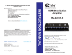
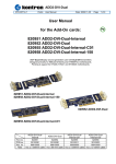
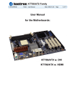
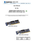
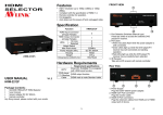
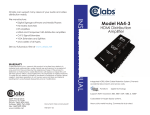
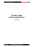
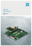
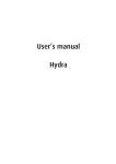
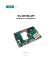
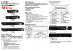
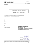
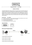
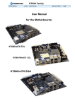
KT-PCIe-DVI-HDMI & KT-PCIe-DVI
KTD-00766-A
Public
User Manual
Date: 2009-03-19
Page
1 of 11
User Manual
for the
820957 KT-PCIe-DVI-HDMI
820959 KT-PCIe-DVI
Designed primarily for KT690 and KT780 motherboards
820957 KT-PCIe-DVI-HDMI
820959 KT-PCIe-DVI
Part no.
PCB no.
Ass. no.
Notes
KT-PCIe-DVI-HDMI
820957
30103330
69100000
KT690 only HDMI
KT-PCIe-DVI
820959
30103330
69100100
Only for KT690
KT-PCIe-DVI-HDMI & KT-PCIe-DVI
KTD-00766-A
Public
User Manual
Date: 2009-03-19
Page
2 of 11
Document revision history.
Revision
A
0
Date
Mar. 19th 2009
Dec. 11th 2008
By
MLA
MLA
Comment
Document name corrected
Preliminary version.
Copyright Notice:
Copyright © 2008, KONTRON Technology A/S, ALL RIGHTS RESERVED.
No part of this document may be reproduced or transmitted in any form or by any means, electronically or
mechanically, for any purpose, without the express written permission of KONTRON Technology A/S.
Trademark Acknowledgement:
Brand and product names are trademarks or registered trademarks of their respective owners.
Disclaimer:
KONTRON Technology A/S reserves the right to make changes, without notice, to any product, including
circuits and/or software described or contained in this manual in order to improve design and/or performance.
Specifications listed in this manual are subject to change without notice. KONTRON Technology assumes no
responsibility or liability for the use of the described product(s), conveys no license or title under any patent,
copyright, or mask work rights to these products, and makes no representations or warranties that these
products are free from patent, copyright, or mask work right infringement, unless otherwise specified.
Applications that are described in this manual are for illustration purposes only. KONTRON Technology A/S
makes no representation or warranty that such application will be suitable for the specified use without
further testing or modification.
Life Support Policy
KONTRON Technology’s PRODUCTS ARE NOT FOR USE AS CRITICAL COMPONENTS IN LIFE
SUPPORT DEVICES OR SYSTEMS WITHOUT EXPRESS WRITTEN APPROVAL OF THE GENERAL
MANAGER OF KONTRON Technology A/S.
As used herein:
1. Life support devices or systems are devices or systems which, (a) are intended for surgical implant into
body, or (b) support or sustain life and whose failure to perform, when properly used in accordance with
instructions for use provided in the labelling, can be reasonably expected to result in significant injury to
the user.
2. A critical component is any component of a life support device or system whose failure to perform can be
reasonably expected to cause the failure of the life support device or system, or to affect its safety or
effectiveness.
KT-PCIe-DVI-HDMI & KT-PCIe-DVI
KTD-00766-A
Public
User Manual
Date: 2009-03-19
Page
3 of 11
Table of contents:
INTRODUCTION ................................................................................................................................................4
MECHANICAL DRAWING.................................................................................................................................5
FUNCTIONAL DIAGRAM ..................................................................................................................................6
CONNECTOR/CABLE KIT DESCRIPTIONS ....................................................................................................8
INSTALLATION GUIDE...................................................................................................................................10
KT-PCIe-DVI-HDMI & KT-PCIe-DVI
KTD-00766-A
Public
User Manual
Date: 2009-03-19
Page
4 of 11
Introduction
When the KT-PCIe-DVI-HDMI card is plugged into the PCI-Expressx16 connector then the motherboard
automatically detects the card and select SDVO output. The card operates at pixel rates of up to 165MHz
per link, supporting 1920x1200 panels at a 60Hz refresh rate.
•
•
•
•
•
•
•
•
•
•
•
•
•
•
Low profile DVI/HDMI module (< 35mm above MB PCB)
High-speed TMDS.
Panel resolution up to 1920x1200 or similar.
Support independent DVI and HDMI dual display.
Including Lock-Clip to fix the module to the PCIe socket.
No tools required for mounting/dismounting the module.
HDMI and DVI Interface, both manage up to 165Mpixels/s
HDMI connector mounted on the IO panel side.
DVI connector via SIL-20p and cable kit 821524.
DVI 1.0 and HDMI compliant.
Complete Windows and DOS support.
Included Low Profile Brackets for HDMI KT780
Included Full Height ATX Bracket for HDMI KT780, with “break-off-plate” for HDMI and for DMI.
Included Low Profile Bracket for DVI (fit the 821524 kit)
Dip-Switches
Lock-Clip
821524
Jumpers
DVI
HDMI
DVI
+
HDMI
HDMI
DVI
820957 KT-PCIe-HDMI-DVI
Brackets included
821524
DVI
Lock-Clip
DVI
(No Jumpers and Dip-Switches)
820959 KT-PCIe-DVI (only for KT690)
KT-PCIe-DVI-HDMI & KT-PCIe-DVI
KTD-00766-A
Public
User Manual
Date: 2009-03-19
Page
5 of 11
Mechanical Drawings
-1.0
0.0
(All measures in mm)
129.4
139.5
34.6
17.0
8.0
4.4
0.0
Motherboard PCB
79.2
120.0
0.0
Low Profile Brackets for HDMI
Low Profile Brackets for DVI
Full Height ATX Bracket for HDMI
KT-PCIe-DVI-HDMI & KT-PCIe-DVI
KTD-00766-A
Public
User Manual
Date: 2009-03-19
Page
Functional Diagram
820957 KT-PCIe-DVI-HDMI
HDMI connector
DVI connector DVI-SIL2
5V Current limited
supply
Terminators
Terminators
Resistor array
DIP switchx8
I2C I/O
TMDS0
TMDS1
PCI-Expressx16 connector
TMDS
Motherboard with multiplexed PCI-Expressx16/TMDS connector
820959 KT-PCIe-DVI
5V Current limited
supply
DVI connector DVI-SIL1
Terminators
Resistor array
I2C I/O
TMDS0
PCI-Expressx16 connector
TMDS
Motherboard with multiplexed PCI-Expressx16/TMDS connector
6 of 11
KT-PCIe-DVI-HDMI & KT-PCIe-DVI
KTD-00766-A
Public
User Manual
Date: 2009-03-19
Page
7 of 11
Jumpers
The Jumpers J1 – J6 are used on the 820957 only and must be setup depending on the actual Motherboard
(KT690 or KT780). The Jumpers are mounted on a 12-pin single in line connector as indicated below.
Pin1
Pin1
o
o
J5
o
o
o
o
o
j4
o
j3
o
o
j2
o
j1
KT690 setting
(J6 not used, J5 on pin 10 - 11)
o
o
o
J6
o
o
j5
o
o
j4
o
o
j3
o
o
j2
o
o
j1
KT780 setting
(Default, all jumper installed)
Dip Switches
KT690 setting
(048h)
1 2 3 4 5 6 7 8
N O
N O
1 2 3 4 5 6 7 8
The DIP Switchx8 is used on the 820957 only and must be setup depending on the actual Motherboard
(KT690 or KT780). The switches are set as indicated below.
KT780 setting
(059h)
KT-PCIe-DVI-HDMI & KT-PCIe-DVI
KTD-00766-A
Public
User Manual
Date: 2009-03-19
Page
8 of 11
Connectors
HDMI connector (available on 820957)
The HDMI connector is of type Samtec HDMI-19-01-S-SM or similar.
Pin No.
Signal
Type
1
2
3
4
5
6
7
8
9
10
11
12
13
14
15
16
17
18
19
20-23
TMDS Data 2+
GND
TMDS Data 2TMDS Data 1+
GND
TMDS Data 1TMDS Data 0+
GND
TMDS Data 0TMDS Clock+
GND
TMDS ClockCEC
NC
DDC Clock
DDC Data
GND
+5V (55mA)
Hot Plug Detect
GND
LVDS OUT
PWR
LVDS OUT
LVDS OUT
PWR
LVDS OUT
LVDS OUT
PWR
LVDS OUT
LVDS OUT
PWR
LVDS OUT
NC
NC
IO
IO
PWR
PWR
I
PWR
Pull Up
2K2
2K2
DVI-SIL2/DVI-SIL1 (available on 820957/820959 respectively)
The “DVI” connector is a Hirose DF19G-20P-1H. Mating connector is Hirose DF19L-20P-1H or similar.
(In order to implement real DVI connector the cable kit 821524 must be used).
Pin No.
Signal
Type
1
2
3
4
5
6
7
8
9
10
11
12
13
14
15
16
17
18
19
20
Shield
GND
GND
+5V (55mA)
Hot Plug Detect
GND
DDC Data
DDC Clock
GND
TMDS ClockTMDS Clock+
GND
TMDS Data 0TMDS Data 0+
GND
TMDS Data 1TMDS Data 1+
GND
TMDS Data 2TMDS Data 2+
GND
GND
PWR
PWR
PWR
I
PWR
IO
IO
PWR
LVDS OUT
LVDS OUT
PWR
LVDS OUT
LVDS OUT
PWR
LVDS OUT
LVDS OUT
PWR
LVDS OUT
LVDS OUT
PWR
PWR
Pull Up
2K2
2K2
KT-PCIe-DVI-HDMI & KT-PCIe-DVI
KTD-00766-A
Public
User Manual
Date: 2009-03-19
Page
9 of 11
Cable kit descriptions
DVI Converter PCB is attached as a brake off module to the KT-PCIe module.
The converter contains two connectors to convert from DVI-SIL (Hirose DF19L-20P-1H) to DVI-I.
The KT-PCIe-modules includes DVI cable 300mm long (PN. 821524) in order to convert the SIL-DVI1/SILDVI2 connector to a DVI-I connector.
The cable wiring is a one-to-one connection.
1
9
17
The DVI-I connector is a Molex 74320-1004 (or similar).
Only DVI Digital output is supported.
(Both DVI-I and DVI-D cables can be connected).
DVI-SIL
Pin No.
1
2
3
4
5
6
7
8
9
10
11
12
13
14
15
16
17
18
19
20
Front view
DVI-I
Pin No.
14
16
15
7
6
24
23
22
17
18
19
9
10
11
1
2
3
8
16
24
Signal
GND
GND
+5V (55mA)
Hot Plug Detect
GND
DDC Data
DDC Clock
GND
TMDS ClockTMDS Clock+
GND
TMDS Data 0TMDS Data 0+
GND
TMDS Data 1TMDS Data 1+
GND
TMDS Data 2TMDS Data 2+
GND
C1 C2
C3 C4
C5
KT-PCIe-DVI-HDMI & KT-PCIe-DVI
KTD-00766-A
Public
User Manual
Date: 2009-03-19
Page
10 of 11
Installation Guide
These KT-PCIe cards fits into a standard PCIe connector like the Molex 877159308 PCIe edge connector
which has no integrated PCIe card lock.
The 820957 and 820959 kits contain:
1. Cable 821524
2. Two Hex Nuts for the DVI connector to fix on a bracket
3. The module
4. Low Profile Brackets for HDMI (only 820957)
5. Low Profile Brackets for DVI
6. Full Height ATX Bracket for HDMI (only 820957)
7. Screw for fixing bracket to module (only 820957)
DVI
+
HDMI
HDMI
DVI
Brake of the DVI Connector adapter.
If DVI shall be used then used the cable kit to interface the module and the DVI Connector adapter.
If DVI Bracket shall be used then fix the DVI connector to the bracket via the two Hex Nuts.
IF required and if HDMI Bracket then fix HDMI Bracket to the module by screw.
Insert the module to the Motherboard (KT690 or KT780 only) via the PCIex16 slot nearest the CPU.
No special settings required in BIOS and OS drivers includes support for the modules.
Boot into OS and use the Catalyst Control Center to select requested display configuration.
KT-PCIe-DVI-HDMI & KT-PCIe-DVI
KTD-00766-A
Public
User Manual
Date: 2009-03-19
Page
11 of 11
The Lock-Clip is use to fix the module into the PCIex16 slot. In order to release the Lock-Clip press by your
thumb on the top part of the Lock-clip as indicated on the picture below.
Other specifications
Power consumption:
The +5V available on both the HDMI and DVI can deliver minimum 55mA continuously and 1A peak. The
output is protected by thermal shutdown circuit.
3.3V 0.3W max.
12V 1.2W max.
Operating temperature: 0-60ºC